EP1616642A1 - Investment casting - Google Patents
Investment casting Download PDFInfo
- Publication number
- EP1616642A1 EP1616642A1 EP05254403A EP05254403A EP1616642A1 EP 1616642 A1 EP1616642 A1 EP 1616642A1 EP 05254403 A EP05254403 A EP 05254403A EP 05254403 A EP05254403 A EP 05254403A EP 1616642 A1 EP1616642 A1 EP 1616642A1
- Authority
- EP
- European Patent Office
- Prior art keywords
- core
- tines
- component
- spine
- investment casting
- Prior art date
- Legal status (The legal status is an assumption and is not a legal conclusion. Google has not performed a legal analysis and makes no representation as to the accuracy of the status listed.)
- Granted
Links
Images


Classifications
-
- B—PERFORMING OPERATIONS; TRANSPORTING
- B22—CASTING; POWDER METALLURGY
- B22C—FOUNDRY MOULDING
- B22C9/00—Moulds or cores; Moulding processes
- B22C9/10—Cores; Manufacture or installation of cores
- B22C9/103—Multipart cores
-
- B—PERFORMING OPERATIONS; TRANSPORTING
- B22—CASTING; POWDER METALLURGY
- B22C—FOUNDRY MOULDING
- B22C7/00—Patterns; Manufacture thereof so far as not provided for in other classes
- B22C7/02—Lost patterns
-
- B—PERFORMING OPERATIONS; TRANSPORTING
- B22—CASTING; POWDER METALLURGY
- B22C—FOUNDRY MOULDING
- B22C9/00—Moulds or cores; Moulding processes
- B22C9/02—Sand moulds or like moulds for shaped castings
- B22C9/04—Use of lost patterns
-
- B—PERFORMING OPERATIONS; TRANSPORTING
- B22—CASTING; POWDER METALLURGY
- B22D—CASTING OF METALS; CASTING OF OTHER SUBSTANCES BY THE SAME PROCESSES OR DEVICES
- B22D29/00—Removing castings from moulds, not restricted to casting processes covered by a single main group; Removing cores; Handling ingots
Definitions
- the invention relates to investment casting. More particularly, the invention relates to the forming of core-containing patterns for investment forming investment casting molds.
- Investment casting is a commonly used technique for forming metallic components having complex geometries, especially hollow components, and is used in the fabrication of superalloy gas turbine engine components.
- Gas turbine engines are widely used in aircraft propulsion, electric power generation, ship propulsion, and pumps. In gas turbine engine applications, efficiency is a prime objective. Improved gas turbine engine efficiency can be obtained by operating at higher temperatures, however current operating temperatures in the turbine section exceed the melting points of the superalloy materials used in turbine components. Consequently, it is a general practice to provide air cooling. Cooling is typically provided by flowing relatively cool air from the compressor section of the engine through passages in the turbine components to be cooled. Such cooling comes with an associated cost in engine efficiency. Consequently, there is a strong desire to provide enhanced specific cooling, maximizing the amount of cooling benefit obtained from a given amount of cooling air. This may be obtained by the use of fine, precisely located, cooling passageway sections.
- a mold is prepared having one or more mold cavities, each having a shape generally corresponding to the part to be cast.
- An exemplary process for preparing the mold involves the use of one or more wax patterns of the part. The patterns are formed by molding wax over ceramic cores generally corresponding to positives of the cooling passages within the parts.
- a ceramic shell is formed around one or more such patterns in a well known fashion. The wax may be removed such as by melting, e.g., in an autoclave. The shell may be fired to harden the shell.
- a mold comprising the shell having one or more part-defining compartments which, in turn, contain the ceramic core(s) defining the cooling passages.
- Molten alloy may then be introduced to the mold to cast the part(s).
- the shell and core may be mechanically and/or chemically removed from the molded part(s).
- the part(s) can then be machined and/or treated in one or more stages.
- the ceramic cores themselves may be formed by molding a mixture of ceramic powder and binder material by injecting the mixture into hardened metal dies. After removal from the dies, the green cores may then be thermally post-processed to remove the binder and fired to sinter the ceramic powder together.
- the trend toward finer cooling features has taxed ceramic core manufacturing techniques.
- the cores defining fine features may be difficult to manufacture and/or, once manufactured, may prove fragile.
- EDM electro-discharge machining
- the refractory metal cores may become damaged during handling or during assembly of the overmolding die. Assuring proper die assembly and release of the injected pattern may require die complexity (e.g., a large number of separate die parts and separate pull directions to accommodate the various RMCs).
- U.S. Patent No. 5,296,308 of Caccavale et al. discloses use of small projections unitarily formed with the feed portions of the ceramic core to position a ceramic core in the die for overmolding the pattern wax. Such projections may then tend to maintain alignment of the core within the shell after shelling and dewaxing.
- One aspect of the invention involves a method for forming an investment casting pattern.
- a first core is installed to a first element of a molding die to leave a first portion of the first core protruding from the first element.
- the first element is assembled with a feed core and a second element of the molding die so that the first portion contacts the feed core and is flexed.
- a material is molded at least partially over the first core and feed core.
- the assembling may include causing engagement between the first core and feed core to at least partially maintain an orientation of the feed core relative to the molding die.
- a second core may be installed to the second element to leave a first portion of the second core protruding from the second element.
- a second core may be installed to the first element to leave a first portion of the second core protruding from the first element.
- the first core may have a spine and a number of tines extending from the spine.
- the first core may comprise, in major weight part, one or more refractory metals.
- the feed core may comprise, in major weight part, one or more ceramic materials and/or refractory metals.
- the material may comprise, in major weight part, one or more waxes.
- An investment casting pattern may be formed as described above.
- One or more coating layers may be applied to the pattern.
- the material may be substantially removed to leave the first core and feed core within a shell formed by the coating layers.
- the method may be used to fabricate a gas turbine engine airfoil element mold.
- Another aspect of the invention involves a method for investment casting.
- An investment casting mold is formed as described above. Molten metal is introduced to the investment casting mold. The molten metal is permitted to solidify. The investment casting mold is destructively removed. The method may be used to fabricate a gas turbine engine component.
- the component includes a spine and a number of tines extending from the spine.
- the spine and tines may be unitarily formed and may consist essentially of a refractory metal-based material, optionally coated.
- the tines may be tapered over a first region from a relatively wide cross-section proximal root at least to a relatively small cross-section intermediate location.
- the tines may be less tapered over a second region, distally of the first region.
- the spine may have integrally-formed spring elements. There may be at least six such tines.
- the spine may provide at least 90% of a mass of the component.
- the tines may be at least five mm in length.
- the spine may define a direction of insertion for inserting the spine into a die. The tines may extend off-parallel to the direction of insertion.
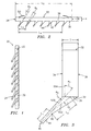
- FIG. 1 shows an exemplary refractory metal core (RMC) 20 which may include a refractory metal substrate and, optionally, a coating (e.g., ceramic).
- RMC substrate materials include Mo, Nb, Ta, and W alone or in combination and in elemental form, alloy, intermetallic, and the like.
- the RMC 20 may be formed by any of a variety of manufacturing techniques, for example, those used to form EDM comb electrodes.
- the substrate may be formed by milling from a refractory metal ingot or stamping and bending a refractory metal sheet, or by build up using multiple sheets. The substrate may then be coated (e.g., with a full ceramic coating or a coating limited to areas that will ultimately contact molten metal).
- the exemplary RMC 20 is intended to be illustrative of one possible general configuration. Other configurations, including simpler and more complex configurations are possible.
- a core precursor could be manufactured having a spine and tines and individual cores separated from the precursor, with the individual cores each having one or more of the tines. Individual cores with one to a few tines could be useful, for example, where only isolated holes or small groups thereof are desired or where it is desired that the holes be of varying shape/size, staggered out of line, of varying spacing, and the like.
- the exemplary RMC 20 may be comb-like, having a back or spine 22 and a row of teeth or tines 24 extending therefrom. Other forms are possible.
- a spine 22 extends between first and second ends 26 and 28 (FIG. 2) and has inboard and outboard surfaces 30 and 32.
- the teeth 24 extend from the inboard surface 30.
- An exemplary number of teeth is 4-20, more narrowly, 6-12.
- the exemplary spine is formed as a portion of a generally right parallelepiped and thus has two additional surfaces or faces 34 and 36.
- the face 34 is a forward face and the face 36 is an aft face (with fore and aft corresponding to generally upstream and downstream positions in an exemplary airfoil to be cast using the RMC 20).
- the exemplary teeth 24 each extend from a proximal root 38 at the inboard surface 30 to a distal tip 40.
- the exemplary teeth each have a proximal portion 42 and a distal portion 44 meeting at an intermediate junction 46.
- the exemplary distal portion 44 is of relatively constant cross-sectional area and shape (e.g., circular or rounded square shape) and extends along a median axis 500 with a length L 1 .
- the proximal portion 42 is of generally proximally divergent cross-sectional area and has a median axis 502 and a characteristic length L 2 .
- the proximal portion may be of generally relatively non-constant cross-sectional shape (e.g., transitioning from the shape of the distal portion to an aftward/downstream divergent shape such as a triangle with a rounded leading corner). Nevertheless, the distal portion could have a non-constant shape and the proximal portion could have a constant shape. Alternatively the entire tine could have constant cross-section.
- a tooth-to-tooth pitch L 3 is defined as the tip separation of adjacent teeth.
- the pitch may be constant or varied as may be the length and cross-sectional shape and dimensions of the teeth. For example, these parameters may be varied to provide a desired cooling distribution.
- the array of teeth has an overall length L 4 .
- the spine has an overall length L 5 , a thickness T, and a principal height H. These parameters may be chosen to permit a desired tooth/hole distribution in view of economy factors (e.g., it may be more economical in labor savings to have one RMC with many teeth rather than a number of RMCs each with a lesser number of teeth).
- the exemplary spine has a pair of arcuate spring tabs 50 extending above a principal portion of the outboard surface 32 (e.g., cut and bent from a remaining portion of the spine).
- the distal portions 44 may extend at an angle ⁇ 1 (FIG. 3) relative to a direction 504 which may be orthogonal to the outboard surface 32 when viewed from the side and an angle ⁇ 2 (FIG. 2) when viewed from the front.
- the distal and proximal portions may be at angles ⁇ 3 and ⁇ 4 from each other when viewed from these directions.
- ⁇ 1 - ⁇ 4 need not be the same for each tooth.
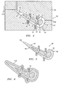
- FIG. 4 shows a number of such RMCs 20 positioned with their spines 22 in compartments 56 of a pattern-forming die 58 having first and second halves 60 and 62.
- the compartments may be shaped and dimensioned to precisely orient and position the associated spines.
- the exemplary die halves are formed of metal or of a composite (e.g., epoxy-based).
- the die halves are shown assembled, meeting along a parting junction 508.
- the die halves may have passageways 64 for the introduction of wax to a void 66 and may be joined and separated along a pull direction 510 which may correspond with the direction 504 of each of the RMCs.
- FIG. 4 further shows a ceramic feed core 70 having portions 72, 73, and 74 (e.g., joined by webs 75) for forming three spanwise feed passageways in an airfoil of the part (e.g., a turbine blade or vane) to be cast.
- Alternative feed cores may be made of other materials such as refractory metals or ceramic/refractory combinations or assemblies.
- the die includes surfaces 76 and 78 for forming suction and pressure side surfaces of the pattern airfoil.
- the inboard surfaces 30 are advantageously shaped and angled to generally correspond to their associated surface 76 or 78. However, portions of the spines could protrude beyond an otherwise continuous curve of the associated surface (e.g., to ultimately form the cast part with a shallow slot connecting outlets of through-holes formed by the tines.
- the tips 40 contact the feed core and help position the feed core.
- the RMCs may be placed in the associated die halves and the feed core then lowered into place and engagement with the RMCs of the lower half (e.g., 62). Thereafter, the upper half may be joined via translation along the pull direction 510, bringing its associated RMCs into engagement with the feed core.
- Other RMCs of other forms may also be installed during the mold assembly process or may be preinstalled to the feed core.
- the tips may be slightly resiliently flexed during the mold assembly process to help position the feed core either during wax molding or later (as described below).
- the flexion may be maintained by cooperation of the spring tabs 50 with base portions 80 of the compartments 56 so as to bias the tips 40 into contact with the feed core.
- the feed core 70 may have recesses for receiving the tips 40 which may improve tip positioning relative to the feed core.
- FIG. 5 shows the pattern 90 after the molding of wax 92 and the removal of the pattern from the die 58.
- the pattern has an exterior surface characterized by suction and pressure side surfaces 94 and 96 extending between a leading edge 98 and a trailing edge 100.
- the strain/flexing of the RMCs during the wax molding process is sufficiently low so that the wax is sufficiently strong to maintain the relative positioning and engagement of the RMCs and feed core 70.
- the pattern may be assembled to a shelling fixture (e.g., via wax welding between upper and lower end plates of the fixture) and a multilayer ceramic slurry/stucco coating 120 (FIG. 6) applied for forming a shell.
- the RMC body portions 22 become embedded in the shell 120.
- a dewax process e.g., in a steam autoclave
- This core and shell assembly may be fired to harden the shell.
- Molten casting material 130 (FIG.
- the RMCs 70 may continue to help maintain the desired position/orientation of the feed core 70.
- the shell 120 may be destructively removed (e.g., broken away via an impact apparatus and/or chemical immersion process) and the RMCs and feed core destructively removed (e.g., via a chemical immersion apparatus) from the cast metal to form a part precursor (e.g., a rough or unfinished part) 140 (FIG. 8). Thereafter, the precursor may be subject to machining, treatment (e.g., thermal, mechanical, or chemical), and coating (e.g., metallic environmental coating/bond coat and/or ceramic heat resistant coating) to form the final component.
- machining, treatment e.g., thermal, mechanical, or chemical
- coating e.g., metallic environmental coating/bond coat and/or ceramic heat resistant coating
- FIG. 8 further shows the discharge cooling passageways formed by the RMC teeth.
- the passageways each have a small cross-section upstream metering portion 150 formed by the teeth distal portions and a downstream diffusing portion 152 formed by the teeth proximal portions.
- Such portions may have shape and dimensions as are known in the art or may yet be developed.
- passageways with arcuate (e.g., non-constant radius of curvature) longitudinal sections, passageways with twist or with at least local downstream-wise decrease in cross-section, or otherwise convoluted passageways may be formed which might be impossible to form via drilling or EDM.
- Exemplary overall tine lengths are 0.5-13mm, more narrowly 3.0-7.0mm, depending essentially upon the wall thickness of the part and the overall tine angle relative to the part outer surface.
- exemplary tine distal portion axes (and thus passageway metering portions) are 15-90° off the part outer surface, more narrowly 20-40°.
- Exemplary cross-sectional areas of the metering portions are 0.03-0.8mm 2 .
- Exemplary maximum transverse dimensions of the metering portions are 0.2-1.0mm.
- FIG. 9 shows an alternate RMC 200 which may be stamped and bent from sheet stock.
- the RMC 200 has a generally flat main body portion 202 extending from an upstream end 204 to a downstream end 206 and having first and second lateral ends 208 and 210.
- the main body portion has a number of projections 212 for forming inlets to a serpentine passageway system in the cast part formed by ultimate removal of the main body portion 202.
- Each projection 212 is continuous with a feed core-engagement portion 214 extending at an angle off-parallel to the main body portion and which may be received in a complementary pocket in the feed core.
- a spine 220 is formed adjacent the downstream end 206.
- Apertures 222 interrupt a proximal portion of the spine 220 and a downstream portion of the body 202. The apertures ultimately form intact casting portions between outlet slots in a similar fashion to outlet slots disclosed in US Patent No. 6,705,831.
- the spine 220 may be positioned within a complementary compartment of the pattern-forming die and brought into flexed engagement with the associated feed core(s) during die assembly.
- the foregoing teachings may be implemented in the manufacturing of pre-existing patterns (core combinations and wax shapes) or to produce novel patterns not yet designed.
Landscapes
- Engineering & Computer Science (AREA)
- Mechanical Engineering (AREA)
- Molds, Cores, And Manufacturing Methods Thereof (AREA)
- Braking Arrangements (AREA)
- Turbine Rotor Nozzle Sealing (AREA)
Abstract
Description
- The invention relates to investment casting. More particularly, the invention relates to the forming of core-containing patterns for investment forming investment casting molds.
- Investment casting is a commonly used technique for forming metallic components having complex geometries, especially hollow components, and is used in the fabrication of superalloy gas turbine engine components.
- Gas turbine engines are widely used in aircraft propulsion, electric power generation, ship propulsion, and pumps. In gas turbine engine applications, efficiency is a prime objective. Improved gas turbine engine efficiency can be obtained by operating at higher temperatures, however current operating temperatures in the turbine section exceed the melting points of the superalloy materials used in turbine components. Consequently, it is a general practice to provide air cooling. Cooling is typically provided by flowing relatively cool air from the compressor section of the engine through passages in the turbine components to be cooled. Such cooling comes with an associated cost in engine efficiency. Consequently, there is a strong desire to provide enhanced specific cooling, maximizing the amount of cooling benefit obtained from a given amount of cooling air. This may be obtained by the use of fine, precisely located, cooling passageway sections.
- A well developed field exists regarding the investment casting of internally-cooled turbine engine parts such as blades, vanes, seals, combustors, and other components. In an exemplary process, a mold is prepared having one or more mold cavities, each having a shape generally corresponding to the part to be cast. An exemplary process for preparing the mold involves the use of one or more wax patterns of the part. The patterns are formed by molding wax over ceramic cores generally corresponding to positives of the cooling passages within the parts. In a shelling process, a ceramic shell is formed around one or more such patterns in a well known fashion. The wax may be removed such as by melting, e.g., in an autoclave. The shell may be fired to harden the shell. This leaves a mold comprising the shell having one or more part-defining compartments which, in turn, contain the ceramic core(s) defining the cooling passages. Molten alloy may then be introduced to the mold to cast the part(s). Upon cooling and solidifying of the alloy, the shell and core may be mechanically and/or chemically removed from the molded part(s). The part(s) can then be machined and/or treated in one or more stages.
- The ceramic cores themselves may be formed by molding a mixture of ceramic powder and binder material by injecting the mixture into hardened metal dies. After removal from the dies, the green cores may then be thermally post-processed to remove the binder and fired to sinter the ceramic powder together. The trend toward finer cooling features has taxed ceramic core manufacturing techniques. The cores defining fine features may be difficult to manufacture and/or, once manufactured, may prove fragile.
- A variety of post-casting techniques were traditionally used to form the fine features. A most basic technique is conventional drilling. Laser drilling is another. Electrical discharge machining or electro-discharge machining (EDM) has also been applied. For example, in machining a row of cooling holes, it is known to use an EDM electrode of a comb-like shape with teeth having complementary shape to the holes to be formed. Various EDM techniques, electrodes, and hole shapes are shown in U.S. Patent Nos. 3,604,884 of Olsson, 4,197,443 of Sidenstick, 4,819,325 of Cross et al., 4,922,076 of Cross et al., 5,382,133 of Moore et al., 5,605,639 of Banks et al., and 5,637,239 of Adamski et al. The hole shapes produced by such EDM techniques are limited by electrode insertion constraints.
- Commonly-assigned co-pending U.S. Patent No. 6,637,500 of Shah et al. discloses exemplary use of a ceramic and refractory metal core combination. With such combinations, generally, the ceramic core(s) provide the large internal features such as trunk passageways while the refractory metal core(s) provide finer features such as outlet passageways. As is the case with the use of multiple ceramic cores, assembling the ceramic and refractory metal cores and maintaining their spatial relationship during wax overmolding presents numerous difficulties. A failure to maintain such relationship can produce potentially unsatisfactory part internal features. It may be difficult to assemble fine refractory metal cores to ceramic cores. Once assembled, it may be difficult to maintain alignment. The refractory metal cores may become damaged during handling or during assembly of the overmolding die. Assuring proper die assembly and release of the injected pattern may require die complexity (e.g., a large number of separate die parts and separate pull directions to accommodate the various RMCs).
- Separately from the development of RMCs, various techniques for positioning the ceramic cores in the pattern molds and resulting shells have been developed. U.S. Patent No. 5,296,308 of Caccavale et al. discloses use of small projections unitarily formed with the feed portions of the ceramic core to position a ceramic core in the die for overmolding the pattern wax. Such projections may then tend to maintain alignment of the core within the shell after shelling and dewaxing.
- Nevertheless, there remains room for further improvement in core assembly techniques.
- One aspect of the invention involves a method for forming an investment casting pattern. A first core is installed to a first element of a molding die to leave a first portion of the first core protruding from the first element. After the installing, the first element is assembled with a feed core and a second element of the molding die so that the first portion contacts the feed core and is flexed. A material is molded at least partially over the first core and feed core.
- In various implementations, the assembling may include causing engagement between the first core and feed core to at least partially maintain an orientation of the feed core relative to the molding die. A second core may be installed to the second element to leave a first portion of the second core protruding from the second element. A second core may be installed to the first element to leave a first portion of the second core protruding from the first element. The first core may have a spine and a number of tines extending from the spine. The first core may comprise, in major weight part, one or more refractory metals. The feed core may comprise, in major weight part, one or more ceramic materials and/or refractory metals. The material may comprise, in major weight part, one or more waxes.
- Another aspect of the invention involves a method for forming an investment casting mold. An investment casting pattern may be formed as described above. One or more coating layers may be applied to the pattern. The material may be substantially removed to leave the first core and feed core within a shell formed by the coating layers. The method may be used to fabricate a gas turbine engine airfoil element mold.
- Another aspect of the invention involves a method for investment casting. An investment casting mold is formed as described above. Molten metal is introduced to the investment casting mold. The molten metal is permitted to solidify. The investment casting mold is destructively removed. The method may be used to fabricate a gas turbine engine component.
- Another aspect of the invention involves a component for forming an investment casting pattern. The component includes a spine and a number of tines extending from the spine.
- In various implementations, the spine and tines may be unitarily formed and may consist essentially of a refractory metal-based material, optionally coated. The tines may be tapered over a first region from a relatively wide cross-section proximal root at least to a relatively small cross-section intermediate location. The tines may be less tapered over a second region, distally of the first region. The spine may have integrally-formed spring elements. There may be at least six such tines. The spine may provide at least 90% of a mass of the component. The tines may be at least five mm in length. The spine may define a direction of insertion for inserting the spine into a die. The tines may extend off-parallel to the direction of insertion.
- The details of one or more embodiments of the invention are set forth in the accompanying drawings and the description below. Other features and advantages of the invention will be apparent from the description and drawings, and from the claims.
-
- FIG. 1 is a view of a refractory metal core (RMC).
- FIG. 2 is a front view of the RMC of FIG. 1.
- FIG. 3 is an end view of the RMC of FIG. 1.
- FIG. 4 is a sectional view of a die for wax molding a core assembly.
- FIG. 5 is a sectional view of an airfoil of a pattern molded in the die of FIG. 4.
- FIG. 6 is a sectional view of a shelled pattern from the precursor of FIG. 5.
- FIG. 7 is a sectional view of cast metal in a shell formed from the shelled pattern of FIG. 6.
- FIG. 8 is a sectional view of a part formed by the cast metal of FIG. 7.
- FIG. 9 is a view of an alternate RMC.
- Like reference numbers and designations in the various drawings indicate like elements.
- FIG. 1 shows an exemplary refractory metal core (RMC) 20 which may include a refractory metal substrate and, optionally, a coating (e.g., ceramic). Exemplary RMC substrate materials include Mo, Nb, Ta, and W alone or in combination and in elemental form, alloy, intermetallic, and the like. The
RMC 20 may be formed by any of a variety of manufacturing techniques, for example, those used to form EDM comb electrodes. For example, the substrate may be formed by milling from a refractory metal ingot or stamping and bending a refractory metal sheet, or by build up using multiple sheets. The substrate may then be coated (e.g., with a full ceramic coating or a coating limited to areas that will ultimately contact molten metal). Theexemplary RMC 20 is intended to be illustrative of one possible general configuration. Other configurations, including simpler and more complex configurations are possible. A core precursor could be manufactured having a spine and tines and individual cores separated from the precursor, with the individual cores each having one or more of the tines. Individual cores with one to a few tines could be useful, for example, where only isolated holes or small groups thereof are desired or where it is desired that the holes be of varying shape/size, staggered out of line, of varying spacing, and the like. - The
exemplary RMC 20 may be comb-like, having a back orspine 22 and a row of teeth ortines 24 extending therefrom. Other forms are possible. Aspine 22 extends between first and second ends 26 and 28 (FIG. 2) and has inboard andoutboard surfaces teeth 24 extend from theinboard surface 30. An exemplary number of teeth is 4-20, more narrowly, 6-12. The exemplary spine is formed as a portion of a generally right parallelepiped and thus has two additional surfaces or faces 34 and 36. In the exemplary implementation, theface 34 is a forward face and theface 36 is an aft face (with fore and aft corresponding to generally upstream and downstream positions in an exemplary airfoil to be cast using the RMC 20). Theexemplary teeth 24 each extend from aproximal root 38 at theinboard surface 30 to adistal tip 40. The exemplary teeth each have aproximal portion 42 and adistal portion 44 meeting at anintermediate junction 46. The exemplarydistal portion 44 is of relatively constant cross-sectional area and shape (e.g., circular or rounded square shape) and extends along amedian axis 500 with a length L1. Theproximal portion 42 is of generally proximally divergent cross-sectional area and has amedian axis 502 and a characteristic length L2. The proximal portion may be of generally relatively non-constant cross-sectional shape (e.g., transitioning from the shape of the distal portion to an aftward/downstream divergent shape such as a triangle with a rounded leading corner). Nevertheless, the distal portion could have a non-constant shape and the proximal portion could have a constant shape. Alternatively the entire tine could have constant cross-section. - In the exemplary embodiment, a tooth-to-tooth pitch L3 is defined as the tip separation of adjacent teeth. The pitch may be constant or varied as may be the length and cross-sectional shape and dimensions of the teeth. For example, these parameters may be varied to provide a desired cooling distribution. The array of teeth has an overall length L4. The spine has an overall length L5, a thickness T, and a principal height H. These parameters may be chosen to permit a desired tooth/hole distribution in view of economy factors (e.g., it may be more economical in labor savings to have one RMC with many teeth rather than a number of RMCs each with a lesser number of teeth). The exemplary spine has a pair of
arcuate spring tabs 50 extending above a principal portion of the outboard surface 32 (e.g., cut and bent from a remaining portion of the spine). - In the exemplary embodiment, the
distal portions 44 may extend at an angle θ1 (FIG. 3) relative to adirection 504 which may be orthogonal to theoutboard surface 32 when viewed from the side and an angle θ2 (FIG. 2) when viewed from the front. Similarly, the distal and proximal portions may be at angles θ3 and θ4 from each other when viewed from these directions. θ1-θ4 need not be the same for each tooth. - FIG. 4 shows a number of
such RMCs 20 positioned with theirspines 22 in compartments 56 of a pattern-formingdie 58 having first andsecond halves parting junction 508. The die halves may havepassageways 64 for the introduction of wax to a void 66 and may be joined and separated along apull direction 510 which may correspond with thedirection 504 of each of the RMCs. - FIG. 4 further shows a
ceramic feed core 70 havingportions surfaces surface - In the exemplary embodiment, the
tips 40 contact the feed core and help position the feed core. Many different assembly techniques are possible. For example, the RMCs may be placed in the associated die halves and the feed core then lowered into place and engagement with the RMCs of the lower half (e.g., 62). Thereafter, the upper half may be joined via translation along thepull direction 510, bringing its associated RMCs into engagement with the feed core. Other RMCs of other forms may also be installed during the mold assembly process or may be preinstalled to the feed core. The tips may be slightly resiliently flexed during the mold assembly process to help position the feed core either during wax molding or later (as described below). The flexion may be maintained by cooperation of thespring tabs 50 withbase portions 80 of the compartments 56 so as to bias thetips 40 into contact with the feed core. Optionally, thefeed core 70 may have recesses for receiving thetips 40 which may improve tip positioning relative to the feed core. - FIG. 5 shows the
pattern 90 after the molding ofwax 92 and the removal of the pattern from thedie 58. The pattern has an exterior surface characterized by suction and pressure side surfaces 94 and 96 extending between aleading edge 98 and a trailingedge 100. Advantageously, the strain/flexing of the RMCs during the wax molding process is sufficiently low so that the wax is sufficiently strong to maintain the relative positioning and engagement of the RMCs and feedcore 70. - After any further preparation (e.g., trimming, patching, and the like), the pattern may be assembled to a shelling fixture (e.g., via wax welding between upper and lower end plates of the fixture) and a multilayer ceramic slurry/stucco coating 120 (FIG. 6) applied for forming a shell. The
RMC body portions 22 become embedded in theshell 120. After the coating dries, a dewax process (e.g., in a steam autoclave) may remove the wax from the pattern leaving theRMCs 20 andfeed core 70 within the shell. This core and shell assembly may be fired to harden the shell. Molten casting material 130 (FIG. 7 - e.g., for forming a nickel-or cobalt-based superalloy part) may then be introduced to the shell to fill the spaces between the core assembly and the shell. During the dewaxing, firing, and/or casting material introduction and cooling, theRMCs 70 may continue to help maintain the desired position/orientation of thefeed core 70. - After solidification of the casting material, the
shell 120 may be destructively removed (e.g., broken away via an impact apparatus and/or chemical immersion process) and the RMCs and feed core destructively removed (e.g., via a chemical immersion apparatus) from the cast metal to form a part precursor (e.g., a rough or unfinished part) 140 (FIG. 8). Thereafter, the precursor may be subject to machining, treatment (e.g., thermal, mechanical, or chemical), and coating (e.g., metallic environmental coating/bond coat and/or ceramic heat resistant coating) to form the final component. - FIG. 8 further shows the discharge cooling passageways formed by the RMC teeth. The passageways each have a small cross-section
upstream metering portion 150 formed by the teeth distal portions and adownstream diffusing portion 152 formed by the teeth proximal portions. Such portions may have shape and dimensions as are known in the art or may yet be developed. For example, passageways with arcuate (e.g., non-constant radius of curvature) longitudinal sections, passageways with twist or with at least local downstream-wise decrease in cross-section, or otherwise convoluted passageways, may be formed which might be impossible to form via drilling or EDM. - Exemplary overall tine lengths are 0.5-13mm, more narrowly 3.0-7.0mm, depending essentially upon the wall thickness of the part and the overall tine angle relative to the part outer surface. For the basic illustrated passageway/tine construction, exemplary tine distal portion axes (and thus passageway metering portions) are 15-90° off the part outer surface, more narrowly 20-40°. Exemplary cross-sectional areas of the metering portions are 0.03-0.8mm2. Exemplary maximum transverse dimensions of the metering portions are 0.2-1.0mm.
- In alternative embodiments, one or more of the tines may intersect each other to form intersecting passageways in the cast part. FIG. 9 shows an
alternate RMC 200 which may be stamped and bent from sheet stock. TheRMC 200 has a generally flatmain body portion 202 extending from anupstream end 204 to adownstream end 206 and having first and second lateral ends 208 and 210. At theupstream end 204, the main body portion has a number ofprojections 212 for forming inlets to a serpentine passageway system in the cast part formed by ultimate removal of themain body portion 202. Eachprojection 212 is continuous with a feed core-engagement portion 214 extending at an angle off-parallel to the main body portion and which may be received in a complementary pocket in the feed core. - A
spine 220 is formed adjacent thedownstream end 206.Apertures 222 interrupt a proximal portion of thespine 220 and a downstream portion of thebody 202. The apertures ultimately form intact casting portions between outlet slots in a similar fashion to outlet slots disclosed in US Patent No. 6,705,831. Prior to pattern forming, thespine 220 may be positioned within a complementary compartment of the pattern-forming die and brought into flexed engagement with the associated feed core(s) during die assembly. - The foregoing teachings may be implemented in the manufacturing of pre-existing patterns (core combinations and wax shapes) or to produce novel patterns not yet designed.
- One or more embodiments of the present invention have been described. Nevertheless, it will be understood that various modifications may be made without departing from the scope of the invention. For example, details of the particular components being manufactured will influence or dictate details of any particular implementation. Thus, other core combinations may be used, including small and/or finely-featured ceramic or other cores in place of the RMCs. Dies having more than two parts may be used. Accordingly, other embodiments are within the scope of the following claims.
Claims (25)
- A method for forming an investment casting pattern comprising:installing a first core (20; 200) to a first element(60; 62) of a molding die (58) to leave a first portion (24; 202) of the first core (20; 200) protruding from the first element (60; 62); andafter said installing, assembling the first element (60, 62) with a feed core (70) and a second element (62; 60) of said molding die (58) so that said first portion (24; 202) contacts the feed core (70) and is flexed; andmolding of a material (92) at least partially over the first core (20; 200) and feed core (70).
- The method of claim 1 wherein:the assembling provides engagement between the first core (20; 200) and feed core (70) to at least partially maintain an orientation of the feed core (70) relative to the molding die (58) .
- The method of claim 1 or 2 further comprising:installing a second core (20; 200) to the second element (62; 60) to leave a first portion (24; 202) of the second core (20; 200) protruding from the second element (62; 60).
- The method of claim 1 or 2 further comprising:installing a second core (20; 200) to the first element (60; 62) to leave a first portion (24; 202) of the second core (20; 200) protruding from the first element (60; 62).
- The method of any preceding claim wherein:said first core (20; 200) has a spine (22; 220) and a plurality of tines (24; 202) extending from the spine (22; 220).
- The method of any of claims 1 to 4 wherein:said first core (200) has a spine (220) and a body (202) extending from the spine (220), the body (202) shaped to form a plurality of intersecting serpentine circuits.
- The method of any preceding claim wherein:said first core (20; 200) comprises, in major weight part, one or more refractory metals; andsaid feed core (70) comprises, in major weight part, one or more ceramic materials.
- The method of any preceding claim wherein:said feed core (70) comprises one or more refractory metals.
- The method of any preceding claim wherein:the material (92) comprises, in major weight part, one or more waxes.
- A method for forming an investment casting mold comprising:forming an investment casting pattern (90) by a method as claimed in any preceding claim;applying one or more coating layers (120) to said pattern (90); andsubstantially removing the material (92) to leave the first core (20; 200) and feed (70) core within a shell formed by the coating layers (120).
- The method of claim 10 used to fabricate a gas turbine engine airfoil element mold.
- A method for investment casting comprising:forming an investment casting mold by a method as claimed in claim 10;introducing molten metal (130) to the investment casting mold;permitting the molten metal to solidify; anddestructively removing the investment casting mold.
- The method of claim 12 used to fabricate a gas turbine engine component (140).
- A component (20) for forming an investment casting pattern comprising:a spine (22); anda plurality of tines (24) extending from the spine.
- The component of claim 14 wherein:the spine (22) and the plurality of tines (24) are unitarily formed and consist essentially of a refractory metal-based material, optionally coated.
- The component of claim 14 or 15 wherein:the tines (24) are tapered from a relatively wide cross-section proximal root (38) at least to a relatively small cross-section intermediate location (46).
- The component of any of claims 14 to 16 wherein:the tines (24) are non-intersecting.
- The component of any of claims 14 to 16 wherein:at least two of the tines (208) intersect each other.
- The component of any of claims 14 to 18 wherein:the tines (24) are tapered over a first region (42) from a relatively wide cross-section proximal root (38) at least to a relatively small cross-section intermediate location (46); andthe tines (24) are less tapered over a second region (44), distally of the first region (42).
- The component of any of claims 14 to 19 wherein:the spine (22) has integrally-formed spring elements (50).
- The component of any of claims 14 to 20 wherein:there are at least six such tines (24).
- The component of any of claims 14 to 21 wherein:the spine (22) provides at least 90% of a mass of the component (20).
- The component of any of claims 14 to 22 wherein:the tines (24) are at least five mm in length.
- The component of any of claims 14 to 23 wherein:the spine (22) defines a direction of insertion for inserting the spine (22) into a die; andthe tines (24) extend off-parallel to said direction of insertion.
- The component of any of claims 14 to 24 wherein:the tines (24) are at a non-constant spacing; andone or more of the tines (24) extend off-parallel to one or more others of the tines (24).
Applications Claiming Priority (1)
| Application Number | Priority Date | Filing Date | Title |
|---|---|---|---|
| US10/891,660 US7172012B1 (en) | 2004-07-14 | 2004-07-14 | Investment casting |
Publications (2)
| Publication Number | Publication Date |
|---|---|
| EP1616642A1 true EP1616642A1 (en) | 2006-01-18 |
| EP1616642B1 EP1616642B1 (en) | 2011-09-14 |
Family
ID=34941835
Family Applications (1)
| Application Number | Title | Priority Date | Filing Date |
|---|---|---|---|
| EP05254403A Not-in-force EP1616642B1 (en) | 2004-07-14 | 2005-07-14 | Investment casting |
Country Status (5)
| Country | Link |
|---|---|
| US (2) | US7172012B1 (en) |
| EP (1) | EP1616642B1 (en) |
| JP (1) | JP2006026742A (en) |
| KR (1) | KR100686658B1 (en) |
| AT (1) | ATE524255T1 (en) |
Cited By (15)
| Publication number | Priority date | Publication date | Assignee | Title |
|---|---|---|---|---|
| EP1759788A2 (en) | 2005-09-01 | 2007-03-07 | United Technologies Corporation | Investment casting of cooled turbine airfoils |
| EP1813365A1 (en) * | 2006-01-27 | 2007-08-01 | Snecma | Method of manufacturing a turbomachine part comprising cooling air outlets |
| EP1772209A3 (en) * | 2005-09-01 | 2008-05-21 | United Technologies Corporation | Investment casting pattern manufacture |
| EP1992431A1 (en) | 2007-05-09 | 2008-11-19 | United Technologies Corporation | Investment casting cores and methods |
| EP2316593A3 (en) * | 2009-10-28 | 2012-01-18 | Howmet Corporation | Fugitive core tooling and method |
| US9284846B2 (en) | 2009-05-20 | 2016-03-15 | Howmet Corporation | Pt-Al-Hf/Zr coating and method |
| EP3162459A1 (en) * | 2015-10-26 | 2017-05-03 | United Technologies Corporation | Additively manufactured core for use in casting an integral cooling circuit of a gas turbine engine component |
| EP3184200A1 (en) * | 2015-12-21 | 2017-06-28 | United Technologies Corporation | Additively manufactured core for use in casting an internal cooling circuit of a gas turbine engine component |
| WO2018111415A1 (en) * | 2016-12-13 | 2018-06-21 | General Electric Company | Integrated casting core-shell structure |
| CN109676088A (en) * | 2017-10-18 | 2019-04-26 | 通用电气公司 | High temperature engineering rigidity core-shell mold for casting |
| CN110072651A (en) * | 2016-12-13 | 2019-07-30 | 通用电气公司 | For making the integral cast core shell structure of the cast member with non-linear bore |
| EP3581293A1 (en) * | 2018-06-11 | 2019-12-18 | United Technologies Corporation | Method for casting cooling holes for an internal cooling circuit of a gas turbine engine component |
| US11351599B2 (en) | 2016-12-13 | 2022-06-07 | General Electric Company | Multi-piece integrated core-shell structure for making cast component |
| EP1876325B2 (en) † | 2006-07-05 | 2023-01-25 | Raytheon Technologies Corporation | External datum system and film cooling hole positioning using core locating holes |
| US11813669B2 (en) | 2016-12-13 | 2023-11-14 | General Electric Company | Method for making an integrated core-shell structure |
Families Citing this family (52)
| Publication number | Priority date | Publication date | Assignee | Title |
|---|---|---|---|---|
| US7172012B1 (en) * | 2004-07-14 | 2007-02-06 | United Technologies Corporation | Investment casting |
| US7569172B2 (en) * | 2005-06-23 | 2009-08-04 | United Technologies Corporation | Method for forming turbine blade with angled internal ribs |
| US7744347B2 (en) * | 2005-11-08 | 2010-06-29 | United Technologies Corporation | Peripheral microcircuit serpentine cooling for turbine airfoils |
| US7686065B2 (en) * | 2006-05-15 | 2010-03-30 | United Technologies Corporation | Investment casting core assembly |
| US20080110024A1 (en) * | 2006-11-14 | 2008-05-15 | Reilly P Brennan | Airfoil casting methods |
| US7980819B2 (en) | 2007-03-14 | 2011-07-19 | United Technologies Corporation | Cast features for a turbine engine airfoil |
| US8066052B2 (en) * | 2007-06-07 | 2011-11-29 | United Technologies Corporation | Cooled wall thickness control |
| US8434997B2 (en) * | 2007-08-22 | 2013-05-07 | United Technologies Corporation | Gas turbine engine case for clearance control |
| US20090112354A1 (en) * | 2007-10-30 | 2009-04-30 | Tahany Ibrahim El-Wardany | Method of determining optimal parameters for machining a workpiece |
| US8236190B2 (en) * | 2008-06-13 | 2012-08-07 | United Technologies Corporation | Recast removal method |
| US9174271B2 (en) * | 2008-07-02 | 2015-11-03 | United Technologies Corporation | Casting system for investment casting process |
| US8157527B2 (en) * | 2008-07-03 | 2012-04-17 | United Technologies Corporation | Airfoil with tapered radial cooling passage |
| FR2933884B1 (en) * | 2008-07-16 | 2012-07-27 | Snecma | PROCESS FOR MANUFACTURING AN AUBING PIECE |
| US8572844B2 (en) * | 2008-08-29 | 2013-11-05 | United Technologies Corporation | Airfoil with leading edge cooling passage |
| US8303252B2 (en) * | 2008-10-16 | 2012-11-06 | United Technologies Corporation | Airfoil with cooling passage providing variable heat transfer rate |
| US8109725B2 (en) * | 2008-12-15 | 2012-02-07 | United Technologies Corporation | Airfoil with wrapped leading edge cooling passage |
| US8240999B2 (en) * | 2009-03-31 | 2012-08-14 | United Technologies Corporation | Internally supported airfoil and method for internally supporting a hollow airfoil during manufacturing |
| EP2445668A2 (en) * | 2009-06-26 | 2012-05-02 | Havasu | Methods for forming faucets and fixtures |
| EP2462079A4 (en) * | 2009-08-09 | 2015-07-29 | Rolls Royce Corp | Support for a fired article |
| US8434546B1 (en) | 2010-03-30 | 2013-05-07 | Honda Motor Co., Ltd. | Casting mold core retention device and method |
| CN102802834B (en) * | 2010-12-07 | 2016-06-22 | 西门子能源有限公司 | Use the model casting of flexible wax pattern tool |
| US20130333855A1 (en) * | 2010-12-07 | 2013-12-19 | Gary B. Merrill | Investment casting utilizing flexible wax pattern tool for supporting a ceramic core along its length during wax injection |
| US9879546B2 (en) * | 2012-06-21 | 2018-01-30 | United Technologies Corporation | Airfoil cooling circuits |
| US9486853B2 (en) * | 2012-09-14 | 2016-11-08 | United Technologies Corporation | Casting of thin wall hollow airfoil sections |
| US20140102656A1 (en) | 2012-10-12 | 2014-04-17 | United Technologies Corporation | Casting Cores and Manufacture Methods |
| JP6037756B2 (en) * | 2012-10-12 | 2016-12-07 | 三菱重工業株式会社 | Mold manufacturing method and mold |
| WO2014113184A1 (en) * | 2013-01-18 | 2014-07-24 | General Electric Company | Method of forming cast-in cooling holes in an aircraft component |
| US9695696B2 (en) | 2013-07-31 | 2017-07-04 | General Electric Company | Turbine blade with sectioned pins |
| US10427213B2 (en) | 2013-07-31 | 2019-10-01 | General Electric Company | Turbine blade with sectioned pins and method of making same |
| US9132476B2 (en) * | 2013-10-31 | 2015-09-15 | Siemens Aktiengesellschaft | Multi-wall gas turbine airfoil cast using a ceramic core formed with a fugitive insert and method of manufacturing same |
| EP3086893B1 (en) | 2013-12-23 | 2019-07-24 | United Technologies Corporation | Lost core structural frame |
| JP6452736B2 (en) * | 2014-06-18 | 2019-01-16 | シーメンス エナジー インコーポレイテッド | Turbine blade investment casting with film hole protrusions for integrated wall thickness control |
| US10337353B2 (en) * | 2014-12-31 | 2019-07-02 | General Electric Company | Casing ring assembly with flowpath conduction cut |
| US20160298462A1 (en) * | 2015-04-09 | 2016-10-13 | United Technologies Corporation | Cooling passages for a gas turbine engine component |
| GB201508795D0 (en) * | 2015-05-22 | 2015-07-01 | Rolls Royce Plc | Cooling of turbine blades |
| US9845728B2 (en) | 2015-10-15 | 2017-12-19 | Rohr, Inc. | Forming a nacelle inlet for a turbine engine propulsion system |
| CN107913980B (en) * | 2016-10-11 | 2024-05-17 | 北京航空材料研究院股份有限公司 | Pipe bending die |
| US10465527B2 (en) * | 2016-11-17 | 2019-11-05 | General Electric Company | Support for a multi-wall core |
| US20180161857A1 (en) * | 2016-12-13 | 2018-06-14 | General Electric Company | Integrated casting core-shell structure for making cast components having thin root components |
| US20180161852A1 (en) * | 2016-12-13 | 2018-06-14 | General Electric Company | Integrated casting core-shell structure with printed tubes for making cast component |
| GB201701365D0 (en) * | 2017-01-27 | 2017-03-15 | Rolls Royce Plc | A ceramic core for an investment casting process |
| DE102017106775A1 (en) * | 2017-03-29 | 2018-10-04 | Nemak, S.A.B. De C.V. | Casting core and process for its production |
| US10974312B2 (en) | 2017-06-28 | 2021-04-13 | General Electric Company | Additively manufactured casting core-shell mold with integrated filter and ceramic shell |
| US11192172B2 (en) | 2017-06-28 | 2021-12-07 | General Electric Company | Additively manufactured interlocking casting core structure with ceramic shell |
| US10391549B2 (en) | 2017-06-28 | 2019-08-27 | General Electric Company | Additively manufactured casting core-shell hybrid mold and ceramic shell |
| US11173542B2 (en) | 2017-06-28 | 2021-11-16 | General Electric Company | Additively manufactured casting core-shell mold and ceramic shell with variable thermal properties |
| US10391670B2 (en) | 2017-06-28 | 2019-08-27 | General Electric Company | Additively manufactured integrated casting core structure with ceramic shell |
| US11433990B2 (en) | 2018-07-09 | 2022-09-06 | Rohr, Inc. | Active laminar flow control system with composite panel |
| US11642720B2 (en) * | 2019-10-16 | 2023-05-09 | Raytheon Technologies Corporation | Integral core bumpers |
| US11203058B2 (en) * | 2019-11-22 | 2021-12-21 | Raytheon Technologies Corporation | Turbine blade casting with strongback core |
| US11685123B2 (en) | 2020-12-01 | 2023-06-27 | Raytheon Technologies Corporation | Erodible support structure for additively manufactured article and process therefor |
| US20240218828A1 (en) | 2022-11-01 | 2024-07-04 | General Electric Company | Gas Turbine Engine |
Citations (9)
| Publication number | Priority date | Publication date | Assignee | Title |
|---|---|---|---|---|
| US3957104A (en) * | 1974-02-27 | 1976-05-18 | The United States Of America As Represented By The Administrator Of The United States National Aeronautics And Space Administration | Method of making an apertured casting |
| GB2150875A (en) * | 1983-12-07 | 1985-07-10 | Rolls Royce | Investment casting |
| WO1997002914A1 (en) * | 1995-07-11 | 1997-01-30 | Extrude Hone Corporation | Investment casting molds and cores |
| WO1999020431A1 (en) * | 1997-10-21 | 1999-04-29 | Allison Advanced Development Company | Airfoil for a gas turbine engine and method of manufacture |
| WO1999059748A1 (en) * | 1998-05-14 | 1999-11-25 | Siemens Aktiengesellschaft | Method and device for producing a metallic hollow body |
| EP1306147A1 (en) * | 2001-10-24 | 2003-05-02 | United Technologies Corporation | Cores for use in precision investment casting |
| EP1358954A1 (en) * | 2002-04-29 | 2003-11-05 | United Technologies Corporation | Shaped core for cast cooling passages and enhanced part definition |
| EP1375824A2 (en) * | 2002-06-19 | 2004-01-02 | United Technologies Corporation | Linked, non-plugging cooling microcircuits |
| EP1531019A1 (en) * | 2003-10-16 | 2005-05-18 | United Technologies Corporation | Refractory metal core wall thickness control |
Family Cites Families (16)
| Publication number | Priority date | Publication date | Assignee | Title |
|---|---|---|---|---|
| US3596703A (en) * | 1968-10-01 | 1971-08-03 | Trw Inc | Method of preventing core shift in casting articles |
| US3604884A (en) | 1969-04-24 | 1971-09-14 | Essar Corp | Electrode feed control for edm machine |
| US4197443A (en) | 1977-09-19 | 1980-04-08 | General Electric Company | Method and apparatus for forming diffused cooling holes in an airfoil |
| EP0084234A1 (en) * | 1981-12-16 | 1983-07-27 | Vickers Plc | Investment casting process and mould |
| US4819325A (en) | 1987-06-01 | 1989-04-11 | Technical Manufacturing Systems, Inc. | Method of forming electro-discharge machining electrode |
| US4922076A (en) | 1987-06-01 | 1990-05-01 | Technical Manufacturing Systems, Inc. | Electro-discharge machining electrode |
| US5296308A (en) * | 1992-08-10 | 1994-03-22 | Howmet Corporation | Investment casting using core with integral wall thickness control means |
| US5382133A (en) | 1993-10-15 | 1995-01-17 | United Technologies Corporation | High coverage shaped diffuser film hole for thin walls |
| US5605639A (en) | 1993-12-21 | 1997-02-25 | United Technologies Corporation | Method of producing diffusion holes in turbine components by a multiple piece electrode |
| US5637239A (en) | 1995-03-31 | 1997-06-10 | United Technologies Corporation | Curved electrode and method for electrical discharge machining curved cooling holes |
| WO1999002431A1 (en) * | 1997-07-11 | 1999-01-21 | Kecskes Gyoergy | Trash container, waste collecting vehicle, and indoor trash bin for collecting waste materials selectively |
| GB0114503D0 (en) * | 2001-06-14 | 2001-08-08 | Rolls Royce Plc | Air cooled aerofoil |
| US6595748B2 (en) * | 2001-08-02 | 2003-07-22 | General Electric Company | Trichannel airfoil leading edge cooling |
| US6556411B1 (en) * | 2002-04-02 | 2003-04-29 | Marconi Communications, Inc. | Purge protection cartridge with three-way attachment clip |
| US7124546B2 (en) * | 2003-11-18 | 2006-10-24 | Pella Corporation | Muntin bar connector with positioning tabs |
| US7172012B1 (en) * | 2004-07-14 | 2007-02-06 | United Technologies Corporation | Investment casting |
-
2004
- 2004-07-14 US US10/891,660 patent/US7172012B1/en not_active Expired - Lifetime
-
2005
- 2005-06-30 KR KR1020050057416A patent/KR100686658B1/en not_active IP Right Cessation
- 2005-07-11 JP JP2005201148A patent/JP2006026742A/en active Pending
- 2005-07-14 AT AT05254403T patent/ATE524255T1/en not_active IP Right Cessation
- 2005-07-14 EP EP05254403A patent/EP1616642B1/en not_active Not-in-force
-
2006
- 2006-01-17 US US11/333,967 patent/US7520312B2/en not_active Expired - Fee Related
Patent Citations (10)
| Publication number | Priority date | Publication date | Assignee | Title |
|---|---|---|---|---|
| US3957104A (en) * | 1974-02-27 | 1976-05-18 | The United States Of America As Represented By The Administrator Of The United States National Aeronautics And Space Administration | Method of making an apertured casting |
| GB2150875A (en) * | 1983-12-07 | 1985-07-10 | Rolls Royce | Investment casting |
| WO1997002914A1 (en) * | 1995-07-11 | 1997-01-30 | Extrude Hone Corporation | Investment casting molds and cores |
| WO1999020431A1 (en) * | 1997-10-21 | 1999-04-29 | Allison Advanced Development Company | Airfoil for a gas turbine engine and method of manufacture |
| US6003756A (en) * | 1997-10-21 | 1999-12-21 | Allison Advanced Development Company | Airfoil for gas a turbine engine and method of manufacture |
| WO1999059748A1 (en) * | 1998-05-14 | 1999-11-25 | Siemens Aktiengesellschaft | Method and device for producing a metallic hollow body |
| EP1306147A1 (en) * | 2001-10-24 | 2003-05-02 | United Technologies Corporation | Cores for use in precision investment casting |
| EP1358954A1 (en) * | 2002-04-29 | 2003-11-05 | United Technologies Corporation | Shaped core for cast cooling passages and enhanced part definition |
| EP1375824A2 (en) * | 2002-06-19 | 2004-01-02 | United Technologies Corporation | Linked, non-plugging cooling microcircuits |
| EP1531019A1 (en) * | 2003-10-16 | 2005-05-18 | United Technologies Corporation | Refractory metal core wall thickness control |
Cited By (26)
| Publication number | Priority date | Publication date | Assignee | Title |
|---|---|---|---|---|
| EP1759788A3 (en) * | 2005-09-01 | 2010-01-20 | United Technologies Corporation | Investment casting of cooled turbine airfoils |
| EP1759788A2 (en) | 2005-09-01 | 2007-03-07 | United Technologies Corporation | Investment casting of cooled turbine airfoils |
| EP2537606A1 (en) | 2005-09-01 | 2012-12-26 | United Technologies Corporation | Investment casting of cooled turbine airfoils |
| EP1772209A3 (en) * | 2005-09-01 | 2008-05-21 | United Technologies Corporation | Investment casting pattern manufacture |
| US7841083B2 (en) | 2006-01-27 | 2010-11-30 | Snecma | Method of manufacturing a turbomachine component that includes cooling air discharge orifices |
| FR2896710A1 (en) * | 2006-01-27 | 2007-08-03 | Snecma Sa | PROCESS FOR MANUFACTURING TURBOMACHINE COMPONENT WITH COOLING AIR EXHAUST ORIFICES |
| CN101007337B (en) * | 2006-01-27 | 2013-01-09 | 斯奈克玛 | Method of manufacturing a turbomachine component that includes cooling air discharge orifices |
| EP1813365A1 (en) * | 2006-01-27 | 2007-08-01 | Snecma | Method of manufacturing a turbomachine part comprising cooling air outlets |
| EP1876325B2 (en) † | 2006-07-05 | 2023-01-25 | Raytheon Technologies Corporation | External datum system and film cooling hole positioning using core locating holes |
| EP1992431A1 (en) | 2007-05-09 | 2008-11-19 | United Technologies Corporation | Investment casting cores and methods |
| US9284846B2 (en) | 2009-05-20 | 2016-03-15 | Howmet Corporation | Pt-Al-Hf/Zr coating and method |
| US9404372B2 (en) | 2009-05-20 | 2016-08-02 | Howmet Corporation | Pt-Al-Hf/Zr coating and method |
| EP2316593A3 (en) * | 2009-10-28 | 2012-01-18 | Howmet Corporation | Fugitive core tooling and method |
| EP3162459A1 (en) * | 2015-10-26 | 2017-05-03 | United Technologies Corporation | Additively manufactured core for use in casting an integral cooling circuit of a gas turbine engine component |
| US10307816B2 (en) | 2015-10-26 | 2019-06-04 | United Technologies Corporation | Additively manufactured core for use in casting an internal cooling circuit of a gas turbine engine component |
| US11059093B2 (en) | 2015-10-26 | 2021-07-13 | Raytheon Technologies Corporation | Additively manufactured core for use in casting an internal cooling circuit of a gas turbine engine component |
| US10226812B2 (en) | 2015-12-21 | 2019-03-12 | United Technologies Corporation | Additively manufactured core for use in casting an internal cooling circuit of a gas turbine engine component |
| EP3184200A1 (en) * | 2015-12-21 | 2017-06-28 | United Technologies Corporation | Additively manufactured core for use in casting an internal cooling circuit of a gas turbine engine component |
| WO2018111415A1 (en) * | 2016-12-13 | 2018-06-21 | General Electric Company | Integrated casting core-shell structure |
| CN110072651A (en) * | 2016-12-13 | 2019-07-30 | 通用电气公司 | For making the integral cast core shell structure of the cast member with non-linear bore |
| CN110072645A (en) * | 2016-12-13 | 2019-07-30 | 通用电气公司 | Integration casting core shell structure |
| US11351599B2 (en) | 2016-12-13 | 2022-06-07 | General Electric Company | Multi-piece integrated core-shell structure for making cast component |
| US11813669B2 (en) | 2016-12-13 | 2023-11-14 | General Electric Company | Method for making an integrated core-shell structure |
| CN109676088A (en) * | 2017-10-18 | 2019-04-26 | 通用电气公司 | High temperature engineering rigidity core-shell mold for casting |
| CN109676088B (en) * | 2017-10-18 | 2022-01-04 | 通用电气公司 | High temperature engineering stiffness core-shell mold for casting |
| EP3581293A1 (en) * | 2018-06-11 | 2019-12-18 | United Technologies Corporation | Method for casting cooling holes for an internal cooling circuit of a gas turbine engine component |
Also Published As
| Publication number | Publication date |
|---|---|
| US7172012B1 (en) | 2007-02-06 |
| EP1616642B1 (en) | 2011-09-14 |
| KR20060048724A (en) | 2006-05-18 |
| JP2006026742A (en) | 2006-02-02 |
| US20080006384A1 (en) | 2008-01-10 |
| KR100686658B1 (en) | 2007-02-26 |
| ATE524255T1 (en) | 2011-09-15 |
| US7520312B2 (en) | 2009-04-21 |
Similar Documents
| Publication | Publication Date | Title |
|---|---|---|
| EP1616642B1 (en) | Investment casting | |
| EP2537606B1 (en) | Investment casting of cooled turbine airfoils | |
| US7673669B2 (en) | Investment casting cores and methods | |
| EP1772209B1 (en) | Investment casting pattern manufacture | |
| EP1914030B1 (en) | Investment casting cores and their use in investment casting | |
| EP1857199B1 (en) | Investment casting core assembly | |
| EP2000232B1 (en) | Cooled wall with thickness control | |
| EP1611978B1 (en) | Investment casting | |
| EP2193859A1 (en) | Castings, casting cores, and mehtods | |
| EP1923152B1 (en) | Trubine blade casting method |
Legal Events
| Date | Code | Title | Description |
|---|---|---|---|
| PUAI | Public reference made under article 153(3) epc to a published international application that has entered the european phase |
Free format text: ORIGINAL CODE: 0009012 |
|
| AK | Designated contracting states |
Kind code of ref document: A1 Designated state(s): AT BE BG CH CY CZ DE DK EE ES FI FR GB GR HU IE IS IT LI LT LU LV MC NL PL PT RO SE SI SK TR |
|
| AX | Request for extension of the european patent |
Extension state: AL BA HR MK YU |
|
| 17P | Request for examination filed |
Effective date: 20060718 |
|
| 17Q | First examination report despatched |
Effective date: 20060818 |
|
| AKX | Designation fees paid |
Designated state(s): AT BE BG CH CY CZ DE DK EE ES FI FR GB GR HU IE IS IT LI LT LU LV MC NL PL PT RO SE SI SK TR |
|
| GRAP | Despatch of communication of intention to grant a patent |
Free format text: ORIGINAL CODE: EPIDOSNIGR1 |
|
| GRAS | Grant fee paid |
Free format text: ORIGINAL CODE: EPIDOSNIGR3 |
|
| GRAA | (expected) grant |
Free format text: ORIGINAL CODE: 0009210 |
|
| AK | Designated contracting states |
Kind code of ref document: B1 Designated state(s): AT BE BG CH CY CZ DE DK EE ES FI FR GB GR HU IE IS IT LI LT LU LV MC NL PL PT RO SE SI SK TR |
|
| REG | Reference to a national code |
Ref country code: GB Ref legal event code: FG4D |
|
| REG | Reference to a national code |
Ref country code: CH Ref legal event code: EP |
|
| REG | Reference to a national code |
Ref country code: DE Ref legal event code: R082 Ref document number: 602005029990 Country of ref document: DE Representative=s name: KSNH PATENTANWAELTE KLUNKER & KOLLEGEN, DE Ref country code: DE Ref legal event code: R082 Ref document number: 602005029990 Country of ref document: DE Representative=s name: KSNH PATENTANWAELTE KLUNKER/SCHMITT-NILSON/HIR, DE |
|
| REG | Reference to a national code |
Ref country code: IE Ref legal event code: FG4D |
|
| REG | Reference to a national code |
Ref country code: DE Ref legal event code: R096 Ref document number: 602005029990 Country of ref document: DE Effective date: 20111117 |
|
| REG | Reference to a national code |
Ref country code: NL Ref legal event code: VDEP Effective date: 20110914 |
|
| PG25 | Lapsed in a contracting state [announced via postgrant information from national office to epo] |
Ref country code: LT Free format text: LAPSE BECAUSE OF FAILURE TO SUBMIT A TRANSLATION OF THE DESCRIPTION OR TO PAY THE FEE WITHIN THE PRESCRIBED TIME-LIMIT Effective date: 20110914 Ref country code: SE Free format text: LAPSE BECAUSE OF FAILURE TO SUBMIT A TRANSLATION OF THE DESCRIPTION OR TO PAY THE FEE WITHIN THE PRESCRIBED TIME-LIMIT Effective date: 20110914 Ref country code: FI Free format text: LAPSE BECAUSE OF FAILURE TO SUBMIT A TRANSLATION OF THE DESCRIPTION OR TO PAY THE FEE WITHIN THE PRESCRIBED TIME-LIMIT Effective date: 20110914 |
|
| LTIE | Lt: invalidation of european patent or patent extension |
Effective date: 20110914 |
|
| PG25 | Lapsed in a contracting state [announced via postgrant information from national office to epo] |
Ref country code: SI Free format text: LAPSE BECAUSE OF FAILURE TO SUBMIT A TRANSLATION OF THE DESCRIPTION OR TO PAY THE FEE WITHIN THE PRESCRIBED TIME-LIMIT Effective date: 20110914 Ref country code: GR Free format text: LAPSE BECAUSE OF FAILURE TO SUBMIT A TRANSLATION OF THE DESCRIPTION OR TO PAY THE FEE WITHIN THE PRESCRIBED TIME-LIMIT Effective date: 20111215 Ref country code: AT Free format text: LAPSE BECAUSE OF FAILURE TO SUBMIT A TRANSLATION OF THE DESCRIPTION OR TO PAY THE FEE WITHIN THE PRESCRIBED TIME-LIMIT Effective date: 20110914 Ref country code: CY Free format text: LAPSE BECAUSE OF FAILURE TO SUBMIT A TRANSLATION OF THE DESCRIPTION OR TO PAY THE FEE WITHIN THE PRESCRIBED TIME-LIMIT Effective date: 20110914 Ref country code: LV Free format text: LAPSE BECAUSE OF FAILURE TO SUBMIT A TRANSLATION OF THE DESCRIPTION OR TO PAY THE FEE WITHIN THE PRESCRIBED TIME-LIMIT Effective date: 20110914 |
|
| REG | Reference to a national code |
Ref country code: AT Ref legal event code: MK05 Ref document number: 524255 Country of ref document: AT Kind code of ref document: T Effective date: 20110914 |
|
| PG25 | Lapsed in a contracting state [announced via postgrant information from national office to epo] |
Ref country code: BE Free format text: LAPSE BECAUSE OF FAILURE TO SUBMIT A TRANSLATION OF THE DESCRIPTION OR TO PAY THE FEE WITHIN THE PRESCRIBED TIME-LIMIT Effective date: 20110914 |
|
| PG25 | Lapsed in a contracting state [announced via postgrant information from national office to epo] |
Ref country code: IS Free format text: LAPSE BECAUSE OF FAILURE TO SUBMIT A TRANSLATION OF THE DESCRIPTION OR TO PAY THE FEE WITHIN THE PRESCRIBED TIME-LIMIT Effective date: 20120114 Ref country code: CZ Free format text: LAPSE BECAUSE OF FAILURE TO SUBMIT A TRANSLATION OF THE DESCRIPTION OR TO PAY THE FEE WITHIN THE PRESCRIBED TIME-LIMIT Effective date: 20110914 Ref country code: SK Free format text: LAPSE BECAUSE OF FAILURE TO SUBMIT A TRANSLATION OF THE DESCRIPTION OR TO PAY THE FEE WITHIN THE PRESCRIBED TIME-LIMIT Effective date: 20110914 |
|
| PG25 | Lapsed in a contracting state [announced via postgrant information from national office to epo] |
Ref country code: IT Free format text: LAPSE BECAUSE OF FAILURE TO SUBMIT A TRANSLATION OF THE DESCRIPTION OR TO PAY THE FEE WITHIN THE PRESCRIBED TIME-LIMIT Effective date: 20110914 Ref country code: NL Free format text: LAPSE BECAUSE OF FAILURE TO SUBMIT A TRANSLATION OF THE DESCRIPTION OR TO PAY THE FEE WITHIN THE PRESCRIBED TIME-LIMIT Effective date: 20110914 Ref country code: PL Free format text: LAPSE BECAUSE OF FAILURE TO SUBMIT A TRANSLATION OF THE DESCRIPTION OR TO PAY THE FEE WITHIN THE PRESCRIBED TIME-LIMIT Effective date: 20110914 Ref country code: EE Free format text: LAPSE BECAUSE OF FAILURE TO SUBMIT A TRANSLATION OF THE DESCRIPTION OR TO PAY THE FEE WITHIN THE PRESCRIBED TIME-LIMIT Effective date: 20110914 Ref country code: PT Free format text: LAPSE BECAUSE OF FAILURE TO SUBMIT A TRANSLATION OF THE DESCRIPTION OR TO PAY THE FEE WITHIN THE PRESCRIBED TIME-LIMIT Effective date: 20120116 Ref country code: RO Free format text: LAPSE BECAUSE OF FAILURE TO SUBMIT A TRANSLATION OF THE DESCRIPTION OR TO PAY THE FEE WITHIN THE PRESCRIBED TIME-LIMIT Effective date: 20110914 |
|
| PLBE | No opposition filed within time limit |
Free format text: ORIGINAL CODE: 0009261 |
|
| STAA | Information on the status of an ep patent application or granted ep patent |
Free format text: STATUS: NO OPPOSITION FILED WITHIN TIME LIMIT |
|
| PG25 | Lapsed in a contracting state [announced via postgrant information from national office to epo] |
Ref country code: DK Free format text: LAPSE BECAUSE OF FAILURE TO SUBMIT A TRANSLATION OF THE DESCRIPTION OR TO PAY THE FEE WITHIN THE PRESCRIBED TIME-LIMIT Effective date: 20110914 |
|
| 26N | No opposition filed |
Effective date: 20120615 |
|
| REG | Reference to a national code |
Ref country code: DE Ref legal event code: R097 Ref document number: 602005029990 Country of ref document: DE Effective date: 20120615 |
|
| PGFP | Annual fee paid to national office [announced via postgrant information from national office to epo] |
Ref country code: DE Payment date: 20120711 Year of fee payment: 8 |
|
| PG25 | Lapsed in a contracting state [announced via postgrant information from national office to epo] |
Ref country code: MC Free format text: LAPSE BECAUSE OF NON-PAYMENT OF DUE FEES Effective date: 20120731 |
|
| REG | Reference to a national code |
Ref country code: CH Ref legal event code: PL |
|
| REG | Reference to a national code |
Ref country code: FR Ref legal event code: ST Effective date: 20130329 |
|
| PG25 | Lapsed in a contracting state [announced via postgrant information from national office to epo] |
Ref country code: ES Free format text: LAPSE BECAUSE OF FAILURE TO SUBMIT A TRANSLATION OF THE DESCRIPTION OR TO PAY THE FEE WITHIN THE PRESCRIBED TIME-LIMIT Effective date: 20111225 Ref country code: CH Free format text: LAPSE BECAUSE OF NON-PAYMENT OF DUE FEES Effective date: 20120731 Ref country code: FR Free format text: LAPSE BECAUSE OF NON-PAYMENT OF DUE FEES Effective date: 20120731 Ref country code: LI Free format text: LAPSE BECAUSE OF NON-PAYMENT OF DUE FEES Effective date: 20120731 |
|
| REG | Reference to a national code |
Ref country code: IE Ref legal event code: MM4A |
|
| PG25 | Lapsed in a contracting state [announced via postgrant information from national office to epo] |
Ref country code: BG Free format text: LAPSE BECAUSE OF FAILURE TO SUBMIT A TRANSLATION OF THE DESCRIPTION OR TO PAY THE FEE WITHIN THE PRESCRIBED TIME-LIMIT Effective date: 20111214 |
|
| PG25 | Lapsed in a contracting state [announced via postgrant information from national office to epo] |
Ref country code: IE Free format text: LAPSE BECAUSE OF NON-PAYMENT OF DUE FEES Effective date: 20120714 |
|
| REG | Reference to a national code |
Ref country code: DE Ref legal event code: R119 Ref document number: 602005029990 Country of ref document: DE Effective date: 20140201 |
|
| PG25 | Lapsed in a contracting state [announced via postgrant information from national office to epo] |
Ref country code: DE Free format text: LAPSE BECAUSE OF NON-PAYMENT OF DUE FEES Effective date: 20140201 Ref country code: TR Free format text: LAPSE BECAUSE OF FAILURE TO SUBMIT A TRANSLATION OF THE DESCRIPTION OR TO PAY THE FEE WITHIN THE PRESCRIBED TIME-LIMIT Effective date: 20110914 |
|
| PG25 | Lapsed in a contracting state [announced via postgrant information from national office to epo] |
Ref country code: LU Free format text: LAPSE BECAUSE OF NON-PAYMENT OF DUE FEES Effective date: 20120714 |
|
| PG25 | Lapsed in a contracting state [announced via postgrant information from national office to epo] |
Ref country code: HU Free format text: LAPSE BECAUSE OF FAILURE TO SUBMIT A TRANSLATION OF THE DESCRIPTION OR TO PAY THE FEE WITHIN THE PRESCRIBED TIME-LIMIT Effective date: 20050714 |
|
| PGFP | Annual fee paid to national office [announced via postgrant information from national office to epo] |
Ref country code: GB Payment date: 20190624 Year of fee payment: 15 |
|
| GBPC | Gb: european patent ceased through non-payment of renewal fee |
Effective date: 20200714 |
|
| PG25 | Lapsed in a contracting state [announced via postgrant information from national office to epo] |
Ref country code: GB Free format text: LAPSE BECAUSE OF NON-PAYMENT OF DUE FEES Effective date: 20200714 |