EP1616641B1 - Fugitive pattern assembly and manufacturing method - Google Patents
Fugitive pattern assembly and manufacturing method Download PDFInfo
- Publication number
- EP1616641B1 EP1616641B1 EP05013946A EP05013946A EP1616641B1 EP 1616641 B1 EP1616641 B1 EP 1616641B1 EP 05013946 A EP05013946 A EP 05013946A EP 05013946 A EP05013946 A EP 05013946A EP 1616641 B1 EP1616641 B1 EP 1616641B1
- Authority
- EP
- European Patent Office
- Prior art keywords
- gating
- fugitive
- pattern
- patterns
- die
- Prior art date
- Legal status (The legal status is an assumption and is not a legal conclusion. Google has not performed a legal analysis and makes no representation as to the accuracy of the status listed.)
- Expired - Lifetime
Links
Images




Classifications
-
- B—PERFORMING OPERATIONS; TRANSPORTING
- B29—WORKING OF PLASTICS; WORKING OF SUBSTANCES IN A PLASTIC STATE IN GENERAL
- B29C—SHAPING OR JOINING OF PLASTICS; SHAPING OF MATERIAL IN A PLASTIC STATE, NOT OTHERWISE PROVIDED FOR; AFTER-TREATMENT OF THE SHAPED PRODUCTS, e.g. REPAIRING
- B29C45/00—Injection moulding, i.e. forcing the required volume of moulding material through a nozzle into a closed mould; Apparatus therefor
- B29C45/14—Injection moulding, i.e. forcing the required volume of moulding material through a nozzle into a closed mould; Apparatus therefor incorporating preformed parts or layers, e.g. injection moulding around inserts or for coating articles
- B29C45/14467—Joining articles or parts of a single article
-
- B—PERFORMING OPERATIONS; TRANSPORTING
- B22—CASTING; POWDER METALLURGY
- B22C—FOUNDRY MOULDING
- B22C7/00—Patterns; Manufacture thereof so far as not provided for in other classes
- B22C7/02—Lost patterns
-
- B—PERFORMING OPERATIONS; TRANSPORTING
- B22—CASTING; POWDER METALLURGY
- B22C—FOUNDRY MOULDING
- B22C7/00—Patterns; Manufacture thereof so far as not provided for in other classes
- B22C7/02—Lost patterns
- B22C7/023—Patterns made from expanded plastic materials
- B22C7/026—Patterns made from expanded plastic materials by assembling preformed parts
-
- B—PERFORMING OPERATIONS; TRANSPORTING
- B22—CASTING; POWDER METALLURGY
- B22C—FOUNDRY MOULDING
- B22C9/00—Moulds or cores; Moulding processes
- B22C9/08—Features with respect to supply of molten metal, e.g. ingates, circular gates, skim gates
- B22C9/082—Sprues, pouring cups
-
- B—PERFORMING OPERATIONS; TRANSPORTING
- B29—WORKING OF PLASTICS; WORKING OF SUBSTANCES IN A PLASTIC STATE IN GENERAL
- B29C—SHAPING OR JOINING OF PLASTICS; SHAPING OF MATERIAL IN A PLASTIC STATE, NOT OTHERWISE PROVIDED FOR; AFTER-TREATMENT OF THE SHAPED PRODUCTS, e.g. REPAIRING
- B29C45/00—Injection moulding, i.e. forcing the required volume of moulding material through a nozzle into a closed mould; Apparatus therefor
- B29C45/14—Injection moulding, i.e. forcing the required volume of moulding material through a nozzle into a closed mould; Apparatus therefor incorporating preformed parts or layers, e.g. injection moulding around inserts or for coating articles
- B29C45/14336—Coating a portion of the article, e.g. the edge of the article
Definitions
- the present invention relates to a fugitive pattern assembly for use making a shell mold for the investment casting of metals and alloys as well as a method for making a fugitive pattern assembly.
- a fugitive or disposable wax pattern is made by injection molding melted wax or other fluid fugitive material in a die corresponding to the configuration of the article to be cast.
- a plurality of such molded patterns are joined to a common gating system made of wax or other fugitive material, and/or to one another by gating, to provide a pattern assembly that can be invested in a ceramic shell mold.
- the gating system typically includes a sprue or runner to which one or more patterns are connected and a pour cup connected to the sprue or runner.
- Multiple fugitive patterns may be joined by gating in end-to-end or other arrangement to one another before being joined to the gating system.
- the actual configuration of the pattern assembly varies depending on the type of cast article to be made in the shell mold; for example, whether the cast article is to be an equiaxed grain, directionally solidified columnar grain, or single crystal casting.
- the patterns are joined to the gating system and/or to one another manually using labor-intensive techniques in a manner that requires a joint that is waterproof and structurally sound to prevent the patterns from separating from the gating system as the shell mold is built up on the pattern assembly.
- the patterns and gating system are made of wax
- the patterns are joined to the gating system by wax welding processes well known in the art to produce a wax weld joint between the patterns and the gating system.
- manually assembled fugitive pattern assemblies can exhibit unwanted variability in pattern locations and joint quality from one pattern to the next and from one pattern assembly to the next.
- the pattern assembly thus produced is invested in a ceramic shell mold by repeatedly dipping the pattern in a ceramic slurry, draining excess slurry, stuccoing with coarse ceramic particles or stucco, and air drying until a desired thickness of a ceramic shell mold is built-up on the pattern assembly.
- the pattern assembly then is removed from the green shell mold typically by heating the shell mold to melt out the pattern assembly, leaving a ceramic shell mold which then is fired at elevated temperature to develop appropriate mold strength for casting a molten metal or alloy.
- US 2003/0075298 discloses a fugitive pattern assembly which is assembled by a computer controlled mechanism which places individual fugitive patterns one by one on a runner support bar, the individual patterns having datum embossments which assist the mechanism in locating the fugitive patterns accurately.
- JP 60083739 A discloses a method of assembling a fugitive pattern assembly in which individual fugitive patterns have gate parts which are inserted into holes in the runner bar and are held in position by heat shrink PVC tubing.
- JP 11244995 discloses a method in which individual lost wax patterns are provided with respective sprue parts and are arranged with the ends of their sprue parts on a recessed part of a runner plate, after which the sprue parts are adhered to the runner plate by pouring molten wax into the recess.
- JP 02055639 A discloses a method of forming a fugitive pattern assembly in which individual wax patterns have runner parts terminating in enlarged root parts and in which a wax runner bar has a longitudinal cavity to receive these root parts and longitudinal lateral slots opening into this cavity, through which slots the runner parts of the individual patterns extend, the individual patterns having their root parts slid one after the other into and along the longitudinal cavity in the runner bar.
- JP 62064450 discloses a method of assembling a two-part wax mould in which the two parts are fitted together and are then fixed together by adhesive injected through a hole in one part which opens into a recess on the other part.
- JP63194839 relates to the production of an integrated wax model in order to decrease man-hour for assembling a plurality of wax models and to improve efficiency. This is achieved by disposing plural pieces of gate parts of the models to the cavity in a runner part of an endless pipe shaped cavity formed by combining metallic moulds and injecting wax into the cavity part, then solidifying the same.
- the cavity of the cylindrical tube-shaped runner part is formed of the injection mould.
- the gate parts of the wax models are disposed on grooves of the outer ring mould.
- the wax is injected into the cavity of the runner part by an injection moulding machine and is solidified. Thereafter, the outer ring mould is removed and the integrated wax models are taken out.
- An object of the invention is to provide an improved method of making a fugitive pattern assembly useful in making shell molds for the lost wax precision investment casting process for single crystal casting wherein the need for manual joining of the fugitive patterns to one another and/or to a gating system is reduced. Accordingly, there is provided a method of making a fugitive pattern assembly according to claim 1.
- the patterns each have an airfoil region with a root region and a tip region wherein the root region of one pattern is interconnected to the tip region of an adjacent pattern by the gating.
- the pattern is placed in a pattern-receiving cavity of the die and the pattern-receiving cavity communicates to a gating cavity of the die when the pattern is received in the pattern-receiving cavity, said fluid gating material being injected into the gating cavity.
- the method includes the step of forming an extension on the pattern such that the extension communicates to the gating cavity of the die when the pattern is received in said pattern-receiving cavity.
- said extension includes a region having a mechanical joint-forming surface.
- the joint-forming surface comprises a dovetail joint-forming surface.
- the fluid gating material comprises wax.
- the pattern is placed in a pattern-receiving cavity of the die.
- the pattern-receiving cavity communicates to a gating cavity of the die.
- the fluid gating material is injected into the gating cavity to form the gating in-situ in the die and connected to the pattern.
- the pattern preferably includes an extension that resides in the gating cavity of the die when the pattern is received in the pattern-receiving cavity such that the extension is captured in the in-situ formed gating.
- the pattern extension includes a mechanical joint-forming surface, such as a dovetail joint-forming surface, to provide a mechanical joint between the pattern and gating.
- the patterns each have an airfoil region with a root region and a tip region wherein the root region of one pattern is interconnected to the tip region of an adjacent pattern by the gating.
- the present invention provides a method of making a fugitive pattern assembly for use in the lost wax investment casting process employed in the high volume commercial production of metal and alloy cast articles wherein a refractory (e.g. ceramic) shell mold is formed on the pattern assembly to replicate its shape and the pattern assembly is subsequently removed to leave an empty refractory shell mold for casting of the metal or alloy.
- a refractory e.g. ceramic
- the invention is described below for purposes of illustration, and not limitation, in relation to a fugitive pattern assembly for use in making a shell mold for investment casting of an airfoil, such as a gas turbine engine blade or vane, although the invention is not limited in this regard and can be practiced to make a pattern assembly for use in making a shell mold for the investment casting of any article.
- the invention is especially useful in making a pattern assembly having a plurality of wax patterns joined to a wax gating system, although the invention can be practiced using any fugitive pattern material, such as conventional pattern wax, solid or foam plastic (e.g. polymeric foam such as polyurethane foam), polymeric pattern materials, and others.
- any fugitive pattern material such as conventional pattern wax, solid or foam plastic (e.g. polymeric foam such as polyurethane foam), polymeric pattern materials, and others.
- FIG. 1 schematically shows a illustratively making a pattern assembly wherein preformed fugitive airfoil patterns 10 are to be joined in end-to-end (root-to-root) relation.
- Each airfoil pattern comprises a root region 11, an airfoil region 12, and a tip region 13.
- Such airfoil patterns 10 are used in making a shell mold for the investment casting of gas turbine engine blades for example.
- the airfoil patterns 10 can be injection molded in a conventional pattern die (not shown) by injecting a fluid fugitive pattern material, such as molten wax, into a suitably configured cavity in the pattern die.
- a fluid fugitive pattern material such as molten wax
- the fugitive patterns can be made using screw type injection molding machines, molten wax pot injection presses, and other injection and/or press machines wherein a molten pattern material is introduced preferably under pressure into a mold cavity.
- Injection molded patterns are well known and described for example in US Patent 6 497 272 and 6 505 672 which are incorporated herein by reference.
- the invention can be practiced using one or more fugitive patterns 10 that is/are formed using any suitable pattern making process and apparatus and that the invention is not limited to injection molding of the patterns.
- the preformed patterns 10 are shown positioned in a gating die 20 in order for gating to be formed in-situ between the root regions 11 of the end-to-end patterns.
- a lower half 20a of the gating die 20 is shown in Figure 1 .
- the upper half of the gating die 20 typically includes similar complementary die features that mate or cooperate with those described below, Figure 1B .
- the gating die half 20a includes portions of cavities 21 and 22 and runner passage 24 that are configured to receive a respective preformed pattern 10.
- additional fugitive patterns similar to patterns 10 would be disposed in the gating die, for example, with each pattern received in respective cavities like cavities 21, which could located on the lefthand and/or righthand sides of the die 20 in Figure 1 in a manner to provide a die cavity arrangement similar to that shown in Figure 3 where a common gating cavity 22 resides between the pattern-receiving cavities 21.
- additional die cavities 21, 22 could be disposed on opposite sides of Figure 1 out of the plane of the drawing on the front and back sides thereof.
- the cavity 22 could extend normal to the plane of the drawing out of the front and/or back of the plane with cavities 21 extending from the cavity 22 along its length into and out of the plane of the drawing.
- Each cavity 21 includes a first root-receiving cavity 21 a adapted to receive the root region 11 with root extension 15r and a second cavity 21 b adapted to receive the airfoil 12 and the tip 13 with tip extension 15t.
- the root region 11 of each pattern 10 is received in close tolerance fit in the root-receiving cavity 21 a so to hold the pattern in desired position in the die and to position root extension 15r in gating cavity 22 of the gating die 20.
- the second cavities 21 b can have any suitable shape.
- the cavities 21 b may have a shape that is complementary to that of the pattern airfoil and tip regions 10 with clearance to permit each pattern to be received in a respective cavity 21 b.
- the second cavities 21 b can have a more generic shape as shown adapted to receive and accommodate patterns having different airfoil and tip regions.
- the gating die half 20a includes portions of an injection runner passage 24 communicated to the gating cavity 22 and through which fluid gating material, such as molten wax, expanding foam plastic or other gating material, is introduced into the gating cavity 22 from a source 25, which for purposes of illustration and not limitation may comprise a source on the injection machine, such as a tank or reservoir of molten gating material.
- a source 25 which for purposes of illustration and not limitation may comprise a source on the injection machine, such as a tank or reservoir of molten gating material.
- the extension 15r on each root region 11 of each fugitive pattern 10 resides in the gating cavity 22 of the die 20 when the root region 11 of the respective pattern 10 is received in the respective first root-receiving cavity 21 a.
- the root extension 15r includes a mechanical joint-forming surface 15s, which is shown as a dovetail joint-forming surface in Figure 1 .
- the preformed fugitive patterns 10 of an article to be cast are placed in the injection die 20 and the fluid gating material, such as molten wax, is injected into the gating cavity 22 about and between the extensions 15r via the runner passage 24 to form in-situ in the die 20 the gating 30 interconnecting the fugitive patterns 10 in end-to-end (root-to-root) relation, Figure 1A .
- the gating 30 is solidified about and between the extensions 15r in a manner to mechanically lock each pattern 10 to the gating 30 by virtue of the wax bonding and mechanical joint therebetween.
- the fluid gating material may comprise the same or a different material from that of the patterns 10.
- the patterns 10 may comprise a particular wax blend while the gating 30 may comprise the same or a different wax blend.
- a pattern assembly 50 Figure 1A , that comprises one or more preformed fugitive patterns 10 of an article to be cast and gating 30 connected to and interconnecting the patterns 10 in end-to-end relation.
- the pattern assembly 50 (called a gang by the inventors) of Figure 1A is removed from the opened gating die 20 and then is joined to a conventional sprue (not shown) and pour cup (not shown) to provide a final pattern assembly for making a shell mold by the lost wax shell mold building process after the runner 54 (formed by solidified wax in runner passage 24) is removed from the pattern assembly 50 at location L.
- Fugitive patterns joined by a sprue or runner to a pour cup are shown in US Patent 4 108 931 ; 6 497 272 which are incorporated herein by reference.
- Figure 1 and 1A illustrate interconnecting the fugitive patterns 10 with their root regions 11 in end-to-end relation
- the invention is not so limited and can be used to interconnect the patterns 10 with gating in other arrangements.
- fugitive patterns 10' are shown interconnected to one another in a manner that the extension 15r' of the root region 11' of one pattern 10' is interconnected to the extension 15t' of the tip region 13' of an adjacent pattern 10' by the gating 30' injected in-situ in the gating cavity 22' of gating die 20' (lower die half 20a' shown).
- extension 15t' of the tip region 13' of one pattern 10' is connected to a preformed fugitive (e.g. wax) pigtail crystal or grain starter and selector member 35' by gating 31' injected in-situ in gating cavity 23' provided in die 20'.
- the extension 15r' of the root region 11' of the other pattern 10' is captured in a gating block 32' injected in-situ in gating cavity 27' for the purpose of producing an attachment that can be used to connect with gating and/or support structure for combining multiple pattern assemblies 50' into a mold setup to make a casting mold.
- the feature formed by cavity 27' can be of various configurations determined by the requirements for attaching assembly 50' to a mold setup.
- the root region 11' of each pattern 10' is received in a root-receiving cavity 21 a' and the tip extension 15t' is received in a tip-receiving cavity 21 c' with the airfoil region residing in respective cavity 21 b'.
- the adjacent extensions 15t', 15r' of the tip and root regions are thereby received in the common gating cavity 22'.
- the extension 15r' of the opposite root region 11' (left hand root region of Figure 2 ) is received in gating cavity 25'.
- the extension 15t' of the opposite tip region 13' (right hand tip region of Figure 2 ) is received in gating cavity 23' as shown in Figure 2 .
- the pigtail crystal or grain starter and selector member 35' is received in fourth cavity 21d' adjacent the gating cavity 23' of the die 20'.
- the preformed fugitive pigtail crystal or grain starter and selector member 35' is included on the pattern assembly of Figure 2A in order to make a shell mold for casting single crystal articles of metal or alloy as is well known.
- the preformed fugitive pigtail crystal or grain starter and selector member 35' is made by injecting molten wax or other fugitive material in a suitable die cavity.
- the preformed fugitive patterns 10' of an article to be cast and the pigtail crystal or grain starter and selector member 35' are placed in the injection die 20' and the fluid gating material, such as molten wax, is injected from source 25' into the gating cavities 22', 23', 27' via the runner passages 24' shown to form in-situ in the die 20' the gating 30', 31', 32', Figure 2A , of pattern assembly 50'.
- the fluid gating material such as molten wax
- the gating 30' is solidified about and between the extensions 15r', 15t' in gating cavity 22' in a manner to mechanically lock each pattern 10' to the gating by virtue of the wax bonding and mechanical joint therebetween.
- the gating 31' is solidified about the extension 15t' in gating cavity 23' in a manner to mechanically lock the pattern 10' to the pigtail crystal or grain starter and selector member 35' by virtue of the wax bonding and mechanical joint therebetween.
- the pattern assembly 50' of Figure 2A is removed from the opened gating die 20' and joined to the pour cup or other structural member by attaching preformed gating pieces or structural pieces typically to the gating 32' to provide a final pattern assembly for making a shell mold by the lost wax shell mold building process after the runner 54' (formed by solidified wax in runner passage 24') is removed from the pattern assembly 50' at locations L'.
- preformed fugitive patterns 100 of an article to be cast are placed in the injection die 200 (lower half 200a shown) and the fluid gating material, such as molten wax, is injected from source 125 into the gating cavity 122 via the runner passage 124 to form in-situ in the die 200 the gating 130 interconnecting the fugitive patterns 100 in side-by-side relation, Figure 3A .
- the fluid gating material such as molten wax
- the preformed patterns 100 are shown positioned in a gating die 200 in order for gating to be formed in-situ between extensions 115 on the root regions 111 of the side-by-side patterns.
- a lower half 200a of the gating die 200 is shown in Figure 3 .
- the upper half of the gating die 200 typically includes similar complementary die features (e.g. cavities 121, 122, and runner passage 124) that mate or cooperate with those described below.
- the gating die half 200a includes portions of first and second pattern-receiving cavities 121 that are configured to receive the preformed patterns 100.
- Each cavity 121 includes a first root extension-receiving cavity 121 a adapted to receive the primary extensions 115 of the root regions 111 of each pattern and a second cavity 121 b adapted to receive the root region 111, airfoil region 112, and tip region 113 of the pattern 100 with clearance.
- the primary extension region 115 of each pattern 100 is received in close tolerance fit in the extension-receiving cavity 121a so to hold the pattern in desired position in the die and to position a secondary root extension 115a in gating cavity 122 of the gating die 200.
- the cavities 121 b can have any suitable shape as described above for cavity 21 b.
- the gating die half 200a includes portions of injection runner passage 124 communicated to the gating cavity 122 and through which fluid gating material, such as molten wax or other gating material, is introduced into the gating cavity 122 from a source 125 of the type described above.
- fluid gating material such as molten wax or other gating material
- the secondary root extension 115a on each root region 111 of each fugitive pattern 100 resides in the gating cavity 122 of the die 120 when the primary extension region 115 of the respective pattern 100 is received in the respective root extension-receiving cavity 121 a.
- the secondary root extension 115a has a mechanical joint-forming surface 115s, which is shown as a dovetail joint-forming surface in Figure 3 .
- the preformed fugitive patterns 100 of an article to be cast are placed in the injection die 200 and the fluid gating material, such as molten wax, is injected into the gating cavity 122 via the runner passage 124 to form in-situ in the die 200 the gating 130 interconnecting the fugitive patterns 100 in side-by-side relation, Figure 3A .
- the gating 130 is solidified about and between the extensions 115a in a manner to mechanically lock each pattern 100 to the gating 130 by virtue of the wax bonding and mechanical joint therebetween.
- a pattern assembly 150 Figure 3A , that comprises one or more preformed fugitive patterns 100 of an article to be cast and gating 130 connected to and interconnecting the patterns 100 in side-by-side relation.
- the pattern assembly 150 of Figure 3A is removed from the opened gating die and then is joined to a runner bar that connects other pattern assemblies 150 and a pour cup to provide a final pattern assembly for making a shell mold by the lost wax shell mold building process after the runner 154 (formed by solidified wax in runner passage 124) is removed from the pattern assembly 150 at location L.
- preformed fugitive patterns 100' of an article to be cast are placed in the injection die 200' and the fluid gating material, such as molten wax, is injected from source 125' into the gating cavities 122', 123' via the runner passages 124' to form in-situ in the die 200' the gating 130', 133' interconnecting the fugitive patterns 100' in side-by-side relation, Figure 4A .
- the root regions 111' of the patterns 100' are interconnected by gating 130', while the tip regions 113' of the patterns 100' are interconnected by the gating 133'.
- the preformed patterns 100' are shown positioned in a gating die 200' in order for gating 130' to be formed in-situ between root extensions 115r' and gating 133' to be formed between the tip extensions 115t' of the side-by-side patterns.
- a lower half 200a' of the gating die 120' is shown in Figure 4 .
- the upper half of the gating die 200' typically includes similar complementary die features (e.g. cavities 121', 122', 123' and runner passage 124') that mate or cooperate with those described below.
- the gating die half 200a' includes portions of pattern-receiving cavity 121' that is configured to receive the patterns 100'.
- the cavity 121' includes a root extension-receiving cavity 121a' adapted to receive the primary extensions 115r' of the root regions 111' of each pattern and a tip extension-receiving cavity 121 c' adapted to receive the primary extensions 115t' of the tip regions 113' of each pattern.
- the cavity 121' also includes a cavity 121b' adapted to receive the root region 111', airfoil region 112', and tip region 113' of the pattern 100' with clearance.
- the primary root and tip extensions 115r' and 115t' of each pattern 100' are received in close tolerance fit in the cavities 121 a', 121c' so as to hold each pattern in desired position in the die and to position secondary root extension 115ra' in gating cavity 122' of the gating die 120' and secondary tip extension 115ta' in gating cavity 123' of the gating die 120'.
- the secondary root and tip extensions 115ra', 115ta' each has a mechanical joint-forming surface 115s', which is shown as a dovetail joint-forming surface in Figure 4 .
- the cavities 121 b' can have any suitable shape as described above for cavity 21 b.
- the gating die half 200a' includes portions of injection runner passages 124' communicated to the gating cavity 122' and 123' through which fluid gating material, such as molten wax or other gating material, is introduced into the gating cavity 122' and 123' from a source 125' of the type described above.
- fluid gating material such as molten wax or other gating material
- the preformed fugitive patterns 100' of an article to be cast are placed in the injection die 200' and the fluid gating material, such as molten wax, is injected into the gating cavities 122', 123' via the runner passages 124' to form in-situ in the die 200' the gating 130', 133' interconnecting the fugitive patterns 100' in side-by-side relation, Figure 4A .
- the gating 130', 133' is solidified about and between the extensions 115ra', 115ta' in a manner to mechanically lock each pattern 100' to the gating 130', 133' by virtue of the wax bonding and mechanical joint therebetween.
- a pattern assembly 150' that comprises one or more preformed fugitive patterns 100' of an article to be cast and gating 130', 133' connected to and interconnecting the patterns 100' in side-by-side relation by injecting fluid gating material in the gating die to form the gating in-situ therein.
- the pattern assembly 150' of Figure 4A is removed from the gating die and then is joined to a runner bar that connects other pattern assemblies 150' and a pour cup to provide a final pattern assembly for making a shell mold by the lost wax shell mold building process after the runner 154' (formed by solidified wax in runner passage 124') is removed from the pattern assembly 150' at location L'.
- the patterns 100' can be joined at the root regions 111' or at the tip regions 113 by the respective gating 130', 133', rather than at both the root and tip regions 111', 113' as shown in Figure 4 .
Landscapes
- Engineering & Computer Science (AREA)
- Mechanical Engineering (AREA)
- Manufacturing & Machinery (AREA)
- Molds, Cores, And Manufacturing Methods Thereof (AREA)
Description
- The present invention relates to a fugitive pattern assembly for use making a shell mold for the investment casting of metals and alloys as well as a method for making a fugitive pattern assembly.
- In the well known "lost wax" process of investment casting, a fugitive or disposable wax pattern is made by injection molding melted wax or other fluid fugitive material in a die corresponding to the configuration of the article to be cast. A plurality of such molded patterns are joined to a common gating system made of wax or other fugitive material, and/or to one another by gating, to provide a pattern assembly that can be invested in a ceramic shell mold. For example, the gating system typically includes a sprue or runner to which one or more patterns are connected and a pour cup connected to the sprue or runner. Multiple fugitive patterns may be joined by gating in end-to-end or other arrangement to one another before being joined to the gating system. The actual configuration of the pattern assembly varies depending on the type of cast article to be made in the shell mold; for example, whether the cast article is to be an equiaxed grain, directionally solidified columnar grain, or single crystal casting.
- Typically, as a result of complexity of the pattern assembly and/or cost of injection dies, the patterns are joined to the gating system and/or to one another manually using labor-intensive techniques in a manner that requires a joint that is waterproof and structurally sound to prevent the patterns from separating from the gating system as the shell mold is built up on the pattern assembly. When the patterns and gating system are made of wax, the patterns are joined to the gating system by wax welding processes well known in the art to produce a wax weld joint between the patterns and the gating system. However, manually assembled fugitive pattern assemblies can exhibit unwanted variability in pattern locations and joint quality from one pattern to the next and from one pattern assembly to the next.
- The pattern assembly thus produced is invested in a ceramic shell mold by repeatedly dipping the pattern in a ceramic slurry, draining excess slurry, stuccoing with coarse ceramic particles or stucco, and air drying until a desired thickness of a ceramic shell mold is built-up on the pattern assembly. The pattern assembly then is removed from the green shell mold typically by heating the shell mold to melt out the pattern assembly, leaving a ceramic shell mold which then is fired at elevated temperature to develop appropriate mold strength for casting a molten metal or alloy.
-
US 2003/0075298 discloses a fugitive pattern assembly which is assembled by a computer controlled mechanism which places individual fugitive patterns one by one on a runner support bar, the individual patterns having datum embossments which assist the mechanism in locating the fugitive patterns accurately. -
JP 60083739 A -
JP 11244995 -
JP 02055639 A -
JP 62064450 -
JP63194839 - An object of the invention is to provide an improved method of making a fugitive pattern assembly useful in making shell molds for the lost wax precision investment casting process for single crystal casting wherein the need for manual joining of the fugitive patterns to one another and/or to a gating system is reduced. Accordingly, there is provided a method of making a fugitive pattern assembly according to claim 1.
- Conveniently, the patterns each have an airfoil region with a root region and a tip region wherein the root region of one pattern is interconnected to the tip region of an adjacent pattern by the gating.
- Conveniently, the pattern is placed in a pattern-receiving cavity of the die and the pattern-receiving cavity communicates to a gating cavity of the die when the pattern is received in the pattern-receiving cavity, said fluid gating material being injected into the gating cavity.
- Preferably, the method includes the step of forming an extension on the pattern such that the extension communicates to the gating cavity of the die when the pattern is received in said pattern-receiving cavity. Advantageously, said extension includes a region having a mechanical joint-forming surface.
- Conveniently, the joint-forming surface comprises a dovetail joint-forming surface. Preferably, the fluid gating material comprises wax.
- In practising a particular method embodiment of the invention, the pattern is placed in a pattern-receiving cavity of the die. The pattern-receiving cavity communicates to a gating cavity of the die. The fluid gating material is injected into the gating cavity to form the gating in-situ in the die and connected to the pattern. The pattern preferably includes an extension that resides in the gating cavity of the die when the pattern is received in the pattern-receiving cavity such that the extension is captured in the in-situ formed gating. The pattern extension includes a mechanical joint-forming surface, such as a dovetail joint-forming surface, to provide a mechanical joint between the pattern and gating.
- In an illustrative embodiment, the patterns each have an airfoil region with a root region and a tip region wherein the root region of one pattern is interconnected to the tip region of an adjacent pattern by the gating.
- So that the invention may be more readily understood, and so that further features thereof may be appreciated, embodiments of the invention will now be described, by way of example, with reference to the accompanying drawings, in which:-
-
Figure 1 is a plan view of a lower half of a gating injection die wherein airfoil patterns are joined in end-to-end relation with root extensions of the patterns joined together by the in-situ injected gating. -
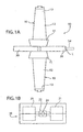
Figure 1A is an elevational view of the pattern assembly produced using the gating die ofFigure 1 . -
Figure 1B is a schematic side elevation of lower and upper die halves of the gating die. -
Figure 2 is a plan view of a lower half of a gating injection die pursuant to the invention wherein airfoil patterns are joined in end-to-end relation with a root extension of one pattern interconnected to a tip extension of an adjacent pattern by in-situ injected gating. -
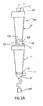
Figure 2A is an elevational view of the pattern assembly produced using the gating die ofFigure 2 . -
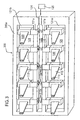
Figure 3 is a plan view of a lower half of a gating injection die wherein airfoil patterns are joined in side-by-side relation with the root extensions of the patterns joined by a common gating runner. -
Figure 3A is an elevational view of the pattern assembly produced using the gating die ofFigure 3 . -
Figure 4 is a plan view of a lower half of a gating injection die wherein airfoil patterns are joined in side-by-side relation with root extensions of the patterns joined by a first common in-situ injected gating and with adjacent tip extensions of the patterns joined by a second common in-situ injected gating. -
Figure 4A is an elevational view of the pattern assembly produced using the gating die ofFigure 4 . - The present invention provides a method of making a fugitive pattern assembly for use in the lost wax investment casting process employed in the high volume commercial production of metal and alloy cast articles wherein a refractory (e.g. ceramic) shell mold is formed on the pattern assembly to replicate its shape and the pattern assembly is subsequently removed to leave an empty refractory shell mold for casting of the metal or alloy. The invention is described below for purposes of illustration, and not limitation, in relation to a fugitive pattern assembly for use in making a shell mold for investment casting of an airfoil, such as a gas turbine engine blade or vane, although the invention is not limited in this regard and can be practiced to make a pattern assembly for use in making a shell mold for the investment casting of any article. The invention is especially useful in making a pattern assembly having a plurality of wax patterns joined to a wax gating system, although the invention can be practiced using any fugitive pattern material, such as conventional pattern wax, solid or foam plastic (e.g. polymeric foam such as polyurethane foam), polymeric pattern materials, and others.
-
Figure 1 schematically shows a illustratively making a pattern assembly wherein preformedfugitive airfoil patterns 10 are to be joined in end-to-end (root-to-root) relation. Each airfoil pattern comprises aroot region 11, anairfoil region 12, and atip region 13.Such airfoil patterns 10 are used in making a shell mold for the investment casting of gas turbine engine blades for example. - The
airfoil patterns 10 can be injection molded in a conventional pattern die (not shown) by injecting a fluid fugitive pattern material, such as molten wax, into a suitably configured cavity in the pattern die. For purposes of illustration and not limitation, the fugitive patterns can be made using screw type injection molding machines, molten wax pot injection presses, and other injection and/or press machines wherein a molten pattern material is introduced preferably under pressure into a mold cavity. Injection molded patterns are well known and described for example inUS Patent 6 497 272 and6 505 672 which are incorporated herein by reference. Those skilled in the art will appreciate that the invention can be practiced using one or morefugitive patterns 10 that is/are formed using any suitable pattern making process and apparatus and that the invention is not limited to injection molding of the patterns. - The
preformed patterns 10 are shown positioned in agating die 20 in order for gating to be formed in-situ between theroot regions 11 of the end-to-end patterns. Alower half 20a of the gating die 20 is shown inFigure 1 . The upper half of the gating die 20 typically includes similar complementary die features that mate or cooperate with those described below,Figure 1B . For example, the gating die half 20a includes portions ofcavities runner passage 24 that are configured to receive a respectivepreformed pattern 10. Although twopatterns 10 are shown in gating die 20 inFigure 1 for purposes of illustration, typically in practice of the invention additional fugitive patterns similar topatterns 10 would be disposed in the gating die, for example, with each pattern received in respective cavities likecavities 21, which could located on the lefthand and/or righthand sides of the die 20 inFigure 1 in a manner to provide a die cavity arrangement similar to that shown inFigure 3 where acommon gating cavity 22 resides between the pattern-receivingcavities 21. Alternately or in addition,additional die cavities Figure 1 out of the plane of the drawing on the front and back sides thereof. For example, thecavity 22 could extend normal to the plane of the drawing out of the front and/or back of the plane withcavities 21 extending from thecavity 22 along its length into and out of the plane of the drawing. - Each
cavity 21 includes a first root-receiving cavity 21 a adapted to receive theroot region 11 withroot extension 15r and asecond cavity 21 b adapted to receive theairfoil 12 and thetip 13 withtip extension 15t. Theroot region 11 of eachpattern 10 is received in close tolerance fit in the root-receivingcavity 21 a so to hold the pattern in desired position in the die and to positionroot extension 15r ingating cavity 22 of thegating die 20. - The
second cavities 21 b can have any suitable shape. For example, thecavities 21 b may have a shape that is complementary to that of the pattern airfoil andtip regions 10 with clearance to permit each pattern to be received in arespective cavity 21 b. Alternatively, thesecond cavities 21 b can have a more generic shape as shown adapted to receive and accommodate patterns having different airfoil and tip regions. - The gating die
half 20a includes portions of aninjection runner passage 24 communicated to thegating cavity 22 and through which fluid gating material, such as molten wax, expanding foam plastic or other gating material, is introduced into thegating cavity 22 from asource 25, which for purposes of illustration and not limitation may comprise a source on the injection machine, such as a tank or reservoir of molten gating material. - The
extension 15r on eachroot region 11 of eachfugitive pattern 10 resides in thegating cavity 22 of the die 20 when theroot region 11 of therespective pattern 10 is received in the respective first root-receivingcavity 21 a. Theroot extension 15r includes a mechanical joint-forming surface 15s, which is shown as a dovetail joint-forming surface inFigure 1 . - The preformed
fugitive patterns 10 of an article to be cast are placed in the injection die 20 and the fluid gating material, such as molten wax, is injected into thegating cavity 22 about and between theextensions 15r via therunner passage 24 to form in-situ in the die 20 thegating 30 interconnecting thefugitive patterns 10 in end-to-end (root-to-root) relation,Figure 1A . Thegating 30 is solidified about and between theextensions 15r in a manner to mechanically lock eachpattern 10 to thegating 30 by virtue of the wax bonding and mechanical joint therebetween. The fluid gating material may comprise the same or a different material from that of thepatterns 10. For example, thepatterns 10 may comprise a particular wax blend while thegating 30 may comprise the same or a different wax blend. - The above-described way can be practiced to make a
pattern assembly 50,Figure 1A , that comprises one or more preformedfugitive patterns 10 of an article to be cast and gating 30 connected to and interconnecting thepatterns 10 in end-to-end relation. The pattern assembly 50 (called a gang by the inventors) ofFigure 1A is removed from the opened gating die 20 and then is joined to a conventional sprue (not shown) and pour cup (not shown) to provide a final pattern assembly for making a shell mold by the lost wax shell mold building process after the runner 54 (formed by solidified wax in runner passage 24) is removed from thepattern assembly 50 at location L. Fugitive patterns joined by a sprue or runner to a pour cup are shown inUS Patent 4 108 931 ;6 497 272 which are incorporated herein by reference. - Although
Figure 1 and1A illustrate interconnecting thefugitive patterns 10 with theirroot regions 11 in end-to-end relation, the invention is not so limited and can be used to interconnect thepatterns 10 with gating in other arrangements. For example, referring toFigures 2 and2A , fugitive patterns 10' are shown interconnected to one another in a manner that theextension 15r' of the root region 11' of one pattern 10' is interconnected to theextension 15t' of the tip region 13' of an adjacent pattern 10' by the gating 30' injected in-situ in the gating cavity 22' of gating die 20' (lower die half 20a' shown). Moreover, theextension 15t' of the tip region 13' of one pattern 10' is connected to a preformed fugitive (e.g. wax) pigtail crystal or grain starter and selector member 35' by gating 31' injected in-situ in gating cavity 23' provided in die 20'. Theextension 15r' of the root region 11' of the other pattern 10' is captured in a gating block 32' injected in-situ in gating cavity 27' for the purpose of producing an attachment that can be used to connect with gating and/or support structure for combining multiple pattern assemblies 50' into a mold setup to make a casting mold. The feature formed by cavity 27' can be of various configurations determined by the requirements for attaching assembly 50' to a mold setup. - To this end, in
Figure 2 , the root region 11' of each pattern 10' is received in a root-receivingcavity 21 a' and thetip extension 15t' is received in a tip-receivingcavity 21 c' with the airfoil region residing inrespective cavity 21 b'. Theadjacent extensions 15t', 15r' of the tip and root regions are thereby received in the common gating cavity 22'. Theextension 15r' of the opposite root region 11' (left hand root region ofFigure 2 ) is received in gating cavity 25'. Theextension 15t' of the opposite tip region 13' (right hand tip region ofFigure 2 ) is received in gating cavity 23' as shown inFigure 2 . - The pigtail crystal or grain starter and selector member 35' is received in
fourth cavity 21d' adjacent the gating cavity 23' of the die 20'. The preformed fugitive pigtail crystal or grain starter and selector member 35' is included on the pattern assembly ofFigure 2A in order to make a shell mold for casting single crystal articles of metal or alloy as is well known. The preformed fugitive pigtail crystal or grain starter and selector member 35' is made by injecting molten wax or other fugitive material in a suitable die cavity. - In practising a method aspect of this embodiment of the invention, the preformed fugitive patterns 10' of an article to be cast and the pigtail crystal or grain starter and selector member 35' are placed in the injection die 20' and the fluid gating material, such as molten wax, is injected from source 25' into the gating cavities 22', 23', 27' via the runner passages 24' shown to form in-situ in the die 20' the gating 30', 31', 32',
Figure 2A , of pattern assembly 50'. The gating 30' is solidified about and between theextensions 15r', 15t' in gating cavity 22' in a manner to mechanically lock each pattern 10' to the gating by virtue of the wax bonding and mechanical joint therebetween. Moreover, the gating 31' is solidified about theextension 15t' in gating cavity 23' in a manner to mechanically lock the pattern 10' to the pigtail crystal or grain starter and selector member 35' by virtue of the wax bonding and mechanical joint therebetween. - The pattern assembly 50' of
Figure 2A is removed from the opened gating die 20' and joined to the pour cup or other structural member by attaching preformed gating pieces or structural pieces typically to the gating 32' to provide a final pattern assembly for making a shell mold by the lost wax shell mold building process after the runner 54' (formed by solidified wax in runner passage 24') is removed from the pattern assembly 50' at locations L'. - As illustrated in
Figure 3 , preformedfugitive patterns 100 of an article to be cast are placed in the injection die 200 (lower half 200a shown) and the fluid gating material, such as molten wax, is injected fromsource 125 into thegating cavity 122 via therunner passage 124 to form in-situ in thedie 200 thegating 130 interconnecting thefugitive patterns 100 in side-by-side relation,Figure 3A . - Pursuant to this aspect, the preformed
patterns 100 are shown positioned in agating die 200 in order for gating to be formed in-situ betweenextensions 115 on theroot regions 111 of the side-by-side patterns. Alower half 200a of the gating die 200 is shown inFigure 3 . The upper half of the gating die 200 typically includes similar complementary die features (e.g. cavities - For example, the gating die
half 200a includes portions of first and second pattern-receivingcavities 121 that are configured to receive the preformedpatterns 100. - Each
cavity 121 includes a first root extension-receivingcavity 121 a adapted to receive theprimary extensions 115 of theroot regions 111 of each pattern and asecond cavity 121 b adapted to receive theroot region 111,airfoil region 112, andtip region 113 of thepattern 100 with clearance. Theprimary extension region 115 of eachpattern 100 is received in close tolerance fit in the extension-receivingcavity 121a so to hold the pattern in desired position in the die and to position asecondary root extension 115a in gatingcavity 122 of the gating die 200. Thecavities 121 b can have any suitable shape as described above forcavity 21 b. - The gating die
half 200a includes portions ofinjection runner passage 124 communicated to thegating cavity 122 and through which fluid gating material, such as molten wax or other gating material, is introduced into thegating cavity 122 from asource 125 of the type described above. - The
secondary root extension 115a on eachroot region 111 of eachfugitive pattern 100 resides in thegating cavity 122 of the die 120 when theprimary extension region 115 of therespective pattern 100 is received in the respective root extension-receivingcavity 121 a. Thesecondary root extension 115a has a mechanical joint-formingsurface 115s, which is shown as a dovetail joint-forming surface inFigure 3 . - The preformed
fugitive patterns 100 of an article to be cast are placed in the injection die 200 and the fluid gating material, such as molten wax, is injected into thegating cavity 122 via therunner passage 124 to form in-situ in thedie 200 thegating 130 interconnecting thefugitive patterns 100 in side-by-side relation,Figure 3A . Thegating 130 is solidified about and between theextensions 115a in a manner to mechanically lock eachpattern 100 to thegating 130 by virtue of the wax bonding and mechanical joint therebetween. - In this way, it can be practiced to make a
pattern assembly 150,Figure 3A , that comprises one or more preformedfugitive patterns 100 of an article to be cast and gating 130 connected to and interconnecting thepatterns 100 in side-by-side relation. Thepattern assembly 150 ofFigure 3A is removed from the opened gating die and then is joined to a runner bar that connectsother pattern assemblies 150 and a pour cup to provide a final pattern assembly for making a shell mold by the lost wax shell mold building process after the runner 154 (formed by solidified wax in runner passage 124) is removed from thepattern assembly 150 at location L. - In practising still another method aspect illustrated in
Figure 4 , preformed fugitive patterns 100' of an article to be cast are placed in the injection die 200' and the fluid gating material, such as molten wax, is injected from source 125' into the gating cavities 122', 123' via the runner passages 124' to form in-situ in the die 200' the gating 130', 133' interconnecting the fugitive patterns 100' in side-by-side relation,Figure 4A . In particular, the root regions 111' of the patterns 100' are interconnected by gating 130', while thetip regions 113' of the patterns 100' are interconnected by the gating 133'. - Pursuant to this aspect, the preformed patterns 100' are shown positioned in a gating die 200' in order for gating 130' to be formed in-situ between
root extensions 115r' and gating 133' to be formed between thetip extensions 115t' of the side-by-side patterns. Alower half 200a' of the gating die 120' is shown inFigure 4 . The upper half of the gating die 200' typically includes similar complementary die features (e.g. cavities 121', 122', 123' and runner passage 124') that mate or cooperate with those described below. - For example, the gating die
half 200a' includes portions of pattern-receiving cavity 121' that is configured to receive the patterns 100'. The cavity 121' includes a root extension-receivingcavity 121a' adapted to receive theprimary extensions 115r' of the root regions 111' of each pattern and a tip extension-receivingcavity 121 c' adapted to receive theprimary extensions 115t' of thetip regions 113' of each pattern. The cavity 121' also includes acavity 121b' adapted to receive the root region 111', airfoil region 112', andtip region 113' of the pattern 100' with clearance. The primary root andtip extensions 115r' and 115t' of each pattern 100' are received in close tolerance fit in thecavities 121 a', 121c' so as to hold each pattern in desired position in the die and to position secondary root extension 115ra' in gating cavity 122' of the gating die 120' and secondary tip extension 115ta' in gating cavity 123' of the gating die 120'. The secondary root and tip extensions 115ra', 115ta' each has a mechanical joint-formingsurface 115s', which is shown as a dovetail joint-forming surface inFigure 4 . As described above, thecavities 121 b' can have any suitable shape as described above forcavity 21 b. - The gating die
half 200a' includes portions of injection runner passages 124' communicated to the gating cavity 122' and 123' through which fluid gating material, such as molten wax or other gating material, is introduced into the gating cavity 122' and 123' from a source 125' of the type described above. - In practising this, the preformed fugitive patterns 100' of an article to be cast are placed in the injection die 200' and the fluid gating material, such as molten wax, is injected into the gating cavities 122', 123' via the runner passages 124' to form in-situ in the die 200' the gating 130', 133' interconnecting the fugitive patterns 100' in side-by-side relation,
Figure 4A . The gating 130', 133' is solidified about and between the extensions 115ra', 115ta' in a manner to mechanically lock each pattern 100' to the gating 130', 133' by virtue of the wax bonding and mechanical joint therebetween. - In this way, it can be practiced to make a pattern assembly 150',
Figure 4A , that comprises one or more preformed fugitive patterns 100' of an article to be cast and gating 130', 133' connected to and interconnecting the patterns 100' in side-by-side relation by injecting fluid gating material in the gating die to form the gating in-situ therein. The pattern assembly 150' ofFigure 4A is removed from the gating die and then is joined to a runner bar that connects other pattern assemblies 150' and a pour cup to provide a final pattern assembly for making a shell mold by the lost wax shell mold building process after the runner 154' (formed by solidified wax in runner passage 124') is removed from the pattern assembly 150' at location L'. It will be apparent that the patterns 100' can be joined at the root regions 111' or at thetip regions 113 by the respective gating 130', 133', rather than at both the root andtip regions 111', 113' as shown inFigure 4 . - Although certain detailed embodiments of the invention are disclosed herein, those skilled in the art will appreciate that the invention is not limited to these embodiments but only as set forth in the following claims.
- When used in this specification and claims, the terms "comprises" and "comprising" and variations thereof mean that the specified features, steps or integers are included. The terms are not to be interpreted to exclude the presence of other features, steps or components.
- The features disclosed in the foregoing description, or the following claims, or the accompanying drawings, expressed in their specific forms or in terms of a means for performing the disclosed function, or a method or process for attaining the disclosed result, as appropriate, may, separately, or in any combination of such features, be utilised for realising the invention in diverse forms thereof.
Claims (8)
- A method making a fugitive pattern assembly, comprising forming a plurality of fugitive patterns (10') of an article to be cast in a single crystal casting mold formed on the pattern assembly wherein each pattern comprises a root end and an opposite tip end, forming a preformed fugitive crystal or grain starter and selector member (35'), placing the patterns (10') in an injection die (20') with at least two fugitive patterns (10') placed in respective pattern- receiving cavities (21b') of a tip-to-root relation with the root region of one of said two fugitive patterns (10') adjacent the tip region of the other of said two patterns (10') in a common first die gating cavity (22') and placing said preformed fugitive member (35') in another cavity (21d') of the injection die with a second die gating cavity (23') between said fugitive member (35') and one of said two fugitive patterns (10') and injecting fluid gating material into the die to form in-situ gating in said first die gating cavity (22') connected to said two fugitive patterns and in said second die gating cavity (23') connected to said fugitive member (21d') and said one of said two said fugitive patterns (10').
- The method of Claim 1 including forming an extension (15r', 15t') on each said fugitive patterns (10') such that the extension communicates with the gating cavity (22', 23') of the die (20') when the pattern is received in said pattern-receiving cavity (21b').
- The method of Claim 2 wherein said extension (15r', 15t') includes a region having a mechanical joint-forming surface.
- The method of Claim 3 wherein the joint-forming surface comprises a dovetail joint-forming surface.
- The method of any preceding claim wherein the fluid gating material comprises wax.
- A method according to any preceding claim wherein said in-situ gating includes a runner (24).
- A method according to Claim 1 wherein said fugitive patterns (10') each have an aerofoil region with a root region and a tip region.
- The method of any preceding claim wherein said preformed fugitive member (35') is a preformed fugitive pigtail crystal or grain starter and selector member.
Applications Claiming Priority (1)
| Application Number | Priority Date | Filing Date | Title |
|---|---|---|---|
| US10/878,655 US7270166B2 (en) | 2004-06-28 | 2004-06-28 | Fugitive pattern assembly and method |
Publications (2)
| Publication Number | Publication Date |
|---|---|
| EP1616641A1 EP1616641A1 (en) | 2006-01-18 |
| EP1616641B1 true EP1616641B1 (en) | 2009-11-04 |
Family
ID=34979794
Family Applications (1)
| Application Number | Title | Priority Date | Filing Date |
|---|---|---|---|
| EP05013946A Expired - Lifetime EP1616641B1 (en) | 2004-06-28 | 2005-06-28 | Fugitive pattern assembly and manufacturing method |
Country Status (4)
| Country | Link |
|---|---|
| US (2) | US7270166B2 (en) |
| EP (1) | EP1616641B1 (en) |
| JP (1) | JP4913369B2 (en) |
| DE (1) | DE602005017447D1 (en) |
Families Citing this family (16)
| Publication number | Priority date | Publication date | Assignee | Title |
|---|---|---|---|---|
| US7270166B2 (en) * | 2004-06-28 | 2007-09-18 | Howmet Corporation | Fugitive pattern assembly and method |
| IT1396907B1 (en) * | 2009-05-22 | 2012-12-20 | Freni Brembo Spa | EQUIPMENT FOR THE CREATION OF FOUNDRY SOULS |
| US20110094698A1 (en) * | 2009-10-28 | 2011-04-28 | Howmet Corporation | Fugitive core tooling and method |
| US8814557B2 (en) * | 2010-03-24 | 2014-08-26 | United Technologies Corporation | Die inserts for die casting |
| US8082972B1 (en) | 2010-10-05 | 2011-12-27 | Mpi Incorporated | System for assembly wax trees using flexible branch |
| US8899303B2 (en) * | 2011-05-10 | 2014-12-02 | Howmet Corporation | Ceramic core with composite insert for casting airfoils |
| US8915289B2 (en) | 2011-05-10 | 2014-12-23 | Howmet Corporation | Ceramic core with composite insert for casting airfoils |
| US9364889B2 (en) * | 2012-01-05 | 2016-06-14 | Ic Patterns, Llc | Foam pattern techniques |
| JP6537221B2 (en) * | 2013-03-13 | 2019-07-03 | ハウメット コーポレイションHowmet Corporation | Ceramic core for airfoil casting with composite inserts |
| JP5646025B2 (en) * | 2013-09-27 | 2014-12-24 | 三菱重工業株式会社 | Turbine blade mold and turbine blade manufacturing method |
| US9162279B1 (en) * | 2015-02-26 | 2015-10-20 | Madesolid, Inc. | Solid to gas phase change material for additive manufacturing |
| DE102015210770A1 (en) * | 2015-06-12 | 2016-12-15 | Rolls-Royce Deutschland Ltd & Co Kg | Component construction, component for a gas turbine and method for producing a component of a gas turbine by metal powder injection molding |
| USD830432S1 (en) * | 2016-06-06 | 2018-10-09 | Ipex Technologies Inc. | 3D printed mold inserts |
| US10010930B1 (en) * | 2016-12-15 | 2018-07-03 | Signicast Llc | Wax mold for investment casting and method of assembling a wax mold |
| US11007687B2 (en) | 2017-10-02 | 2021-05-18 | Legacy Foam Llc | Polyurethane injection system and method |
| CN113118394B (en) * | 2019-12-30 | 2023-05-26 | 安徽应流航源动力科技有限公司 | Tool for placing wax mould of engine guide vane |
Family Cites Families (34)
| Publication number | Priority date | Publication date | Assignee | Title |
|---|---|---|---|---|
| US2503630A (en) * | 1945-10-29 | 1950-04-11 | Thompson Prod Inc | Method of making impeller bucket dies |
| US3254379A (en) * | 1960-08-19 | 1966-06-07 | Atlantic Casting & Engineering | Expendable molding shape for precision casting |
| GB1342290A (en) * | 1971-04-22 | 1974-01-03 | Foseco Trading Ag | Investment casting |
| JPS536087B2 (en) * | 1974-10-02 | 1978-03-04 | ||
| US4108931A (en) * | 1975-01-15 | 1978-08-22 | Ralph Ogden | System of making molds for investment casting |
| JPS555146A (en) * | 1978-06-26 | 1980-01-16 | Suzuki Motor Co Ltd | Wax pattern in investment casting |
| JPS6061140A (en) * | 1983-09-14 | 1985-04-08 | Mitsubishi Metal Corp | Manufacture of wax tree in lost wax method |
| JPS6083739A (en) | 1983-10-12 | 1985-05-13 | Toyota Motor Corp | Assembling method of pattern for investment casting mold |
| US4676294A (en) * | 1984-06-27 | 1987-06-30 | Berger Robert P | Gate |
| JPS6264450A (en) | 1985-09-13 | 1987-03-23 | Mazda Motor Corp | Method for joining patterns for lost wax |
| JPS63194839A (en) * | 1987-02-10 | 1988-08-12 | Hitachi Metal Precision:Kk | Production of integrated wax model |
| US4766942A (en) * | 1987-12-16 | 1988-08-30 | Ford Motor Company | Evaporative pattern assembly and method of making |
| JPH0255639A (en) | 1988-08-19 | 1990-02-26 | Mazda Motor Corp | Manufacture of wax pattern in lost wax casting |
| US4981167A (en) * | 1989-11-30 | 1991-01-01 | Steve Anderson | Method of forming products by low turbulence, uniform cross section investment casting |
| US4972897A (en) * | 1990-02-02 | 1990-11-27 | Mds Products Inc. | Spiral sprue loop |
| US5113925A (en) * | 1990-10-09 | 1992-05-19 | Pcast Equipment Corporation | Investment casting of metal matrix composites |
| US5303762A (en) * | 1992-07-17 | 1994-04-19 | Hitchiner Manufacturing Co., Inc. | Countergravity casting apparatus and method |
| US5465780A (en) * | 1993-11-23 | 1995-11-14 | Alliedsignal Inc. | Laser machining of ceramic cores |
| FR2714858B1 (en) * | 1994-01-12 | 1996-02-09 | Snecma | Method for manufacturing a shell mold made of ceramic material for a lost model foundry. |
| US5538798A (en) * | 1995-04-12 | 1996-07-23 | Niemin Porter & Co. D/B/A Cast Alloys, Inc. | Investment casting gating for metal wood golf club heads |
| US5735336A (en) * | 1995-08-11 | 1998-04-07 | Johnson & Johnson Professional, Inc. | Investment casting method utilizing polymeric casting patterns |
| JP2902379B2 (en) * | 1997-04-25 | 1999-06-07 | 三菱製鋼株式会社 | How to make a wax pattern |
| JPH11244995A (en) | 1998-02-28 | 1999-09-14 | Yasugi Seisakusho:Kk | Bonding method of vanishing model |
| GB9805371D0 (en) * | 1998-03-14 | 1998-05-06 | Rolls Royce Plc | A method of making a ceramic shell mould and a method of casting |
| US6497272B1 (en) * | 1999-10-14 | 2002-12-24 | Howmet Research Corporation | Single crystal casting mold |
| JP2002263821A (en) * | 2001-03-05 | 2002-09-17 | Taiheiyo Cement Corp | Joining structure and joining method |
| US20020124987A1 (en) * | 2001-03-09 | 2002-09-12 | Soderstrom Mark L. | Casting apparatus with mold handling/positioning fixture |
| US6505678B2 (en) * | 2001-04-17 | 2003-01-14 | Howmet Research Corporation | Ceramic core with locators and method |
| US6505672B2 (en) * | 2001-05-22 | 2003-01-14 | Howmet Research Corporation | Fugitive patterns for investment casting |
| US7575038B2 (en) * | 2001-06-11 | 2009-08-18 | Howmet Research Corporation | Single crystal seed |
| US6910519B2 (en) * | 2001-11-28 | 2005-06-28 | Mpi Incorporated | Process and apparatus for assembly of wax trees |
| JP2004098075A (en) * | 2002-09-05 | 2004-04-02 | Daido Steel Co Ltd | Casting method for cantilever blades |
| US6929050B2 (en) * | 2003-06-20 | 2005-08-16 | Mpi Incorporated | Wax runners for casting |
| US7270166B2 (en) * | 2004-06-28 | 2007-09-18 | Howmet Corporation | Fugitive pattern assembly and method |
-
2004
- 2004-06-28 US US10/878,655 patent/US7270166B2/en not_active Expired - Lifetime
-
2005
- 2005-06-27 JP JP2005186087A patent/JP4913369B2/en not_active Expired - Lifetime
- 2005-06-28 DE DE602005017447T patent/DE602005017447D1/en not_active Expired - Lifetime
- 2005-06-28 EP EP05013946A patent/EP1616641B1/en not_active Expired - Lifetime
-
2007
- 2007-08-22 US US11/894,999 patent/US8678073B2/en not_active Expired - Fee Related
Also Published As
| Publication number | Publication date |
|---|---|
| JP2006007325A (en) | 2006-01-12 |
| US20080035295A1 (en) | 2008-02-14 |
| US8678073B2 (en) | 2014-03-25 |
| US7270166B2 (en) | 2007-09-18 |
| US20050284598A1 (en) | 2005-12-29 |
| DE602005017447D1 (en) | 2009-12-17 |
| EP1616641A1 (en) | 2006-01-18 |
| JP4913369B2 (en) | 2012-04-11 |
Similar Documents
| Publication | Publication Date | Title |
|---|---|---|
| US8678073B2 (en) | Fugitive pattern assembly and method | |
| US4421153A (en) | Method of making an aerofoil member for a gas turbine engine | |
| US4434835A (en) | Method of making a blade aerofoil for a gas turbine engine | |
| EP2777842B1 (en) | Cast-in cooling features especially for turbine airfoils | |
| EP1381481B1 (en) | Multi-wall core and process | |
| US4384607A (en) | Method of manufacturing a blade or vane for a gas turbine engine | |
| EP1671720B1 (en) | Ceramic casting core and method | |
| US4289191A (en) | Injection molding thermoplastic patterns having ceramic cores | |
| US20110094698A1 (en) | Fugitive core tooling and method | |
| ZA200503068B (en) | Investment casting | |
| JP2017013091A (en) | Wax mold and lost wax casting method | |
| CN115255284A (en) | Combined sand core for machine tool casting and casting method | |
| EP1419834B1 (en) | Master mould for precursor and precursor for investment casting | |
| KR20220017116A (en) | Manufacturing method for hot stamping mold and its mold | |
| JPH09168855A (en) | Method and apparatus for manufacturing resin molding die | |
| US12330210B2 (en) | Method for producing flexible tooling for casting a ceramic core | |
| JP3833499B2 (en) | Manufacturing method of casting parts having multiple passages | |
| CN121820545A (en) | Pouring system and forming method for complex-structure starting turbine casting | |
| JP3228263B2 (en) | Manufacturing method of hollow molded products | |
| JPH07124690A (en) | Nesting mold for wax pattern molding | |
| KR100531456B1 (en) | Manufacturing method of empted Jewelry | |
| KR20060027584A (en) | Manufacturing method of hollow precious metal | |
| WO2000013819A1 (en) | Composite cores for foundry casting | |
| JPH09168856A (en) | Method and apparatus for manufacturing resin molding die | |
| JPS62176631A (en) | Production of die |
Legal Events
| Date | Code | Title | Description |
|---|---|---|---|
| PUAI | Public reference made under article 153(3) epc to a published international application that has entered the european phase |
Free format text: ORIGINAL CODE: 0009012 |
|
| AK | Designated contracting states |
Kind code of ref document: A1 Designated state(s): AT BE BG CH CY CZ DE DK EE ES FI FR GB GR HU IE IS IT LI LT LU MC NL PL PT RO SE SI SK TR |
|
| AX | Request for extension of the european patent |
Extension state: AL BA HR LV MK YU |
|
| 17P | Request for examination filed |
Effective date: 20060712 |
|
| 17Q | First examination report despatched |
Effective date: 20060816 |
|
| AKX | Designation fees paid |
Designated state(s): DE FR GB |
|
| 17Q | First examination report despatched |
Effective date: 20060816 |
|
| GRAP | Despatch of communication of intention to grant a patent |
Free format text: ORIGINAL CODE: EPIDOSNIGR1 |
|
| GRAS | Grant fee paid |
Free format text: ORIGINAL CODE: EPIDOSNIGR3 |
|
| GRAA | (expected) grant |
Free format text: ORIGINAL CODE: 0009210 |
|
| AK | Designated contracting states |
Kind code of ref document: B1 Designated state(s): DE FR GB |
|
| REG | Reference to a national code |
Ref country code: GB Ref legal event code: FG4D |
|
| REF | Corresponds to: |
Ref document number: 602005017447 Country of ref document: DE Date of ref document: 20091217 Kind code of ref document: P |
|
| PLBE | No opposition filed within time limit |
Free format text: ORIGINAL CODE: 0009261 |
|
| STAA | Information on the status of an ep patent application or granted ep patent |
Free format text: STATUS: NO OPPOSITION FILED WITHIN TIME LIMIT |
|
| 26N | No opposition filed |
Effective date: 20100805 |
|
| REG | Reference to a national code |
Ref country code: FR Ref legal event code: PLFP Year of fee payment: 11 |
|
| REG | Reference to a national code |
Ref country code: FR Ref legal event code: PLFP Year of fee payment: 12 |
|
| REG | Reference to a national code |
Ref country code: FR Ref legal event code: PLFP Year of fee payment: 13 |
|
| REG | Reference to a national code |
Ref country code: FR Ref legal event code: PLFP Year of fee payment: 14 |
|
| PGFP | Annual fee paid to national office [announced via postgrant information from national office to epo] |
Ref country code: GB Payment date: 20240521 Year of fee payment: 20 |
|
| PGFP | Annual fee paid to national office [announced via postgrant information from national office to epo] |
Ref country code: DE Payment date: 20240521 Year of fee payment: 20 |
|
| PGFP | Annual fee paid to national office [announced via postgrant information from national office to epo] |
Ref country code: FR Payment date: 20240521 Year of fee payment: 20 |
|
| REG | Reference to a national code |
Ref country code: DE Ref legal event code: R071 Ref document number: 602005017447 Country of ref document: DE |
|
| PG25 | Lapsed in a contracting state [announced via postgrant information from national office to epo] |
Ref country code: GB Free format text: LAPSE BECAUSE OF EXPIRATION OF PROTECTION Effective date: 20250627 |
|
| REG | Reference to a national code |
Ref country code: GB Ref legal event code: PE20 Expiry date: 20250627 |