EP1616533A2 - Intravascular stent apparatus - Google Patents
Intravascular stent apparatus Download PDFInfo
- Publication number
- EP1616533A2 EP1616533A2 EP05019033A EP05019033A EP1616533A2 EP 1616533 A2 EP1616533 A2 EP 1616533A2 EP 05019033 A EP05019033 A EP 05019033A EP 05019033 A EP05019033 A EP 05019033A EP 1616533 A2 EP1616533 A2 EP 1616533A2
- Authority
- EP
- European Patent Office
- Prior art keywords
- expansion
- strut
- column
- stent
- connecting strut
- Prior art date
- Legal status (The legal status is an assumption and is not a legal conclusion. Google has not performed a legal analysis and makes no representation as to the accuracy of the status listed.)
- Granted
Links
Images

Classifications
-
- A—HUMAN NECESSITIES
- A61—MEDICAL OR VETERINARY SCIENCE; HYGIENE
- A61F—FILTERS IMPLANTABLE INTO BLOOD VESSELS; PROSTHESES; DEVICES PROVIDING PATENCY TO, OR PREVENTING COLLAPSING OF, TUBULAR STRUCTURES OF THE BODY, e.g. STENTS; ORTHOPAEDIC, NURSING OR CONTRACEPTIVE DEVICES; FOMENTATION; TREATMENT OR PROTECTION OF EYES OR EARS; BANDAGES, DRESSINGS OR ABSORBENT PADS; FIRST-AID KITS
- A61F2/00—Filters implantable into blood vessels; Prostheses, i.e. artificial substitutes or replacements for parts of the body; Appliances for connecting them with the body; Devices providing patency to, or preventing collapsing of, tubular structures of the body, e.g. stents
- A61F2/82—Devices providing patency to, or preventing collapsing of, tubular structures of the body, e.g. stents
- A61F2/86—Stents in a form characterised by the wire-like elements; Stents in the form characterised by a net-like or mesh-like structure
- A61F2/90—Stents in a form characterised by the wire-like elements; Stents in the form characterised by a net-like or mesh-like structure characterised by a net-like or mesh-like structure
- A61F2/91—Stents in a form characterised by the wire-like elements; Stents in the form characterised by a net-like or mesh-like structure characterised by a net-like or mesh-like structure made from perforated sheet material or tubes, e.g. perforated by laser cuts or etched holes
- A61F2/915—Stents in a form characterised by the wire-like elements; Stents in the form characterised by a net-like or mesh-like structure characterised by a net-like or mesh-like structure made from perforated sheet material or tubes, e.g. perforated by laser cuts or etched holes with bands having a meander structure, adjacent bands being connected to each other
-
- A—HUMAN NECESSITIES
- A61—MEDICAL OR VETERINARY SCIENCE; HYGIENE
- A61F—FILTERS IMPLANTABLE INTO BLOOD VESSELS; PROSTHESES; DEVICES PROVIDING PATENCY TO, OR PREVENTING COLLAPSING OF, TUBULAR STRUCTURES OF THE BODY, e.g. STENTS; ORTHOPAEDIC, NURSING OR CONTRACEPTIVE DEVICES; FOMENTATION; TREATMENT OR PROTECTION OF EYES OR EARS; BANDAGES, DRESSINGS OR ABSORBENT PADS; FIRST-AID KITS
- A61F2/00—Filters implantable into blood vessels; Prostheses, i.e. artificial substitutes or replacements for parts of the body; Appliances for connecting them with the body; Devices providing patency to, or preventing collapsing of, tubular structures of the body, e.g. stents
- A61F2/82—Devices providing patency to, or preventing collapsing of, tubular structures of the body, e.g. stents
- A61F2002/825—Devices providing patency to, or preventing collapsing of, tubular structures of the body, e.g. stents having longitudinal struts
-
- A—HUMAN NECESSITIES
- A61—MEDICAL OR VETERINARY SCIENCE; HYGIENE
- A61F—FILTERS IMPLANTABLE INTO BLOOD VESSELS; PROSTHESES; DEVICES PROVIDING PATENCY TO, OR PREVENTING COLLAPSING OF, TUBULAR STRUCTURES OF THE BODY, e.g. STENTS; ORTHOPAEDIC, NURSING OR CONTRACEPTIVE DEVICES; FOMENTATION; TREATMENT OR PROTECTION OF EYES OR EARS; BANDAGES, DRESSINGS OR ABSORBENT PADS; FIRST-AID KITS
- A61F2/00—Filters implantable into blood vessels; Prostheses, i.e. artificial substitutes or replacements for parts of the body; Appliances for connecting them with the body; Devices providing patency to, or preventing collapsing of, tubular structures of the body, e.g. stents
- A61F2/82—Devices providing patency to, or preventing collapsing of, tubular structures of the body, e.g. stents
- A61F2/86—Stents in a form characterised by the wire-like elements; Stents in the form characterised by a net-like or mesh-like structure
- A61F2/90—Stents in a form characterised by the wire-like elements; Stents in the form characterised by a net-like or mesh-like structure characterised by a net-like or mesh-like structure
- A61F2/91—Stents in a form characterised by the wire-like elements; Stents in the form characterised by a net-like or mesh-like structure characterised by a net-like or mesh-like structure made from perforated sheet material or tubes, e.g. perforated by laser cuts or etched holes
- A61F2/915—Stents in a form characterised by the wire-like elements; Stents in the form characterised by a net-like or mesh-like structure characterised by a net-like or mesh-like structure made from perforated sheet material or tubes, e.g. perforated by laser cuts or etched holes with bands having a meander structure, adjacent bands being connected to each other
- A61F2002/91525—Stents in a form characterised by the wire-like elements; Stents in the form characterised by a net-like or mesh-like structure characterised by a net-like or mesh-like structure made from perforated sheet material or tubes, e.g. perforated by laser cuts or etched holes with bands having a meander structure, adjacent bands being connected to each other within the whole structure different bands showing different meander characteristics, e.g. frequency or amplitude
-
- A—HUMAN NECESSITIES
- A61—MEDICAL OR VETERINARY SCIENCE; HYGIENE
- A61F—FILTERS IMPLANTABLE INTO BLOOD VESSELS; PROSTHESES; DEVICES PROVIDING PATENCY TO, OR PREVENTING COLLAPSING OF, TUBULAR STRUCTURES OF THE BODY, e.g. STENTS; ORTHOPAEDIC, NURSING OR CONTRACEPTIVE DEVICES; FOMENTATION; TREATMENT OR PROTECTION OF EYES OR EARS; BANDAGES, DRESSINGS OR ABSORBENT PADS; FIRST-AID KITS
- A61F2/00—Filters implantable into blood vessels; Prostheses, i.e. artificial substitutes or replacements for parts of the body; Appliances for connecting them with the body; Devices providing patency to, or preventing collapsing of, tubular structures of the body, e.g. stents
- A61F2/82—Devices providing patency to, or preventing collapsing of, tubular structures of the body, e.g. stents
- A61F2/86—Stents in a form characterised by the wire-like elements; Stents in the form characterised by a net-like or mesh-like structure
- A61F2/90—Stents in a form characterised by the wire-like elements; Stents in the form characterised by a net-like or mesh-like structure characterised by a net-like or mesh-like structure
- A61F2/91—Stents in a form characterised by the wire-like elements; Stents in the form characterised by a net-like or mesh-like structure characterised by a net-like or mesh-like structure made from perforated sheet material or tubes, e.g. perforated by laser cuts or etched holes
- A61F2/915—Stents in a form characterised by the wire-like elements; Stents in the form characterised by a net-like or mesh-like structure characterised by a net-like or mesh-like structure made from perforated sheet material or tubes, e.g. perforated by laser cuts or etched holes with bands having a meander structure, adjacent bands being connected to each other
- A61F2002/91533—Stents in a form characterised by the wire-like elements; Stents in the form characterised by a net-like or mesh-like structure characterised by a net-like or mesh-like structure made from perforated sheet material or tubes, e.g. perforated by laser cuts or etched holes with bands having a meander structure, adjacent bands being connected to each other characterised by the phase between adjacent bands
-
- A—HUMAN NECESSITIES
- A61—MEDICAL OR VETERINARY SCIENCE; HYGIENE
- A61F—FILTERS IMPLANTABLE INTO BLOOD VESSELS; PROSTHESES; DEVICES PROVIDING PATENCY TO, OR PREVENTING COLLAPSING OF, TUBULAR STRUCTURES OF THE BODY, e.g. STENTS; ORTHOPAEDIC, NURSING OR CONTRACEPTIVE DEVICES; FOMENTATION; TREATMENT OR PROTECTION OF EYES OR EARS; BANDAGES, DRESSINGS OR ABSORBENT PADS; FIRST-AID KITS
- A61F2/00—Filters implantable into blood vessels; Prostheses, i.e. artificial substitutes or replacements for parts of the body; Appliances for connecting them with the body; Devices providing patency to, or preventing collapsing of, tubular structures of the body, e.g. stents
- A61F2/82—Devices providing patency to, or preventing collapsing of, tubular structures of the body, e.g. stents
- A61F2/86—Stents in a form characterised by the wire-like elements; Stents in the form characterised by a net-like or mesh-like structure
- A61F2/90—Stents in a form characterised by the wire-like elements; Stents in the form characterised by a net-like or mesh-like structure characterised by a net-like or mesh-like structure
- A61F2/91—Stents in a form characterised by the wire-like elements; Stents in the form characterised by a net-like or mesh-like structure characterised by a net-like or mesh-like structure made from perforated sheet material or tubes, e.g. perforated by laser cuts or etched holes
- A61F2/915—Stents in a form characterised by the wire-like elements; Stents in the form characterised by a net-like or mesh-like structure characterised by a net-like or mesh-like structure made from perforated sheet material or tubes, e.g. perforated by laser cuts or etched holes with bands having a meander structure, adjacent bands being connected to each other
- A61F2002/9155—Adjacent bands being connected to each other
- A61F2002/91558—Adjacent bands being connected to each other connected peak to peak
-
- A—HUMAN NECESSITIES
- A61—MEDICAL OR VETERINARY SCIENCE; HYGIENE
- A61F—FILTERS IMPLANTABLE INTO BLOOD VESSELS; PROSTHESES; DEVICES PROVIDING PATENCY TO, OR PREVENTING COLLAPSING OF, TUBULAR STRUCTURES OF THE BODY, e.g. STENTS; ORTHOPAEDIC, NURSING OR CONTRACEPTIVE DEVICES; FOMENTATION; TREATMENT OR PROTECTION OF EYES OR EARS; BANDAGES, DRESSINGS OR ABSORBENT PADS; FIRST-AID KITS
- A61F2/00—Filters implantable into blood vessels; Prostheses, i.e. artificial substitutes or replacements for parts of the body; Appliances for connecting them with the body; Devices providing patency to, or preventing collapsing of, tubular structures of the body, e.g. stents
- A61F2/82—Devices providing patency to, or preventing collapsing of, tubular structures of the body, e.g. stents
- A61F2/86—Stents in a form characterised by the wire-like elements; Stents in the form characterised by a net-like or mesh-like structure
- A61F2/90—Stents in a form characterised by the wire-like elements; Stents in the form characterised by a net-like or mesh-like structure characterised by a net-like or mesh-like structure
- A61F2/91—Stents in a form characterised by the wire-like elements; Stents in the form characterised by a net-like or mesh-like structure characterised by a net-like or mesh-like structure made from perforated sheet material or tubes, e.g. perforated by laser cuts or etched holes
- A61F2/915—Stents in a form characterised by the wire-like elements; Stents in the form characterised by a net-like or mesh-like structure characterised by a net-like or mesh-like structure made from perforated sheet material or tubes, e.g. perforated by laser cuts or etched holes with bands having a meander structure, adjacent bands being connected to each other
- A61F2002/9155—Adjacent bands being connected to each other
- A61F2002/91583—Adjacent bands being connected to each other by a bridge, whereby at least one of its ends is connected along the length of a strut between two consecutive apices within a band
-
- A—HUMAN NECESSITIES
- A61—MEDICAL OR VETERINARY SCIENCE; HYGIENE
- A61F—FILTERS IMPLANTABLE INTO BLOOD VESSELS; PROSTHESES; DEVICES PROVIDING PATENCY TO, OR PREVENTING COLLAPSING OF, TUBULAR STRUCTURES OF THE BODY, e.g. STENTS; ORTHOPAEDIC, NURSING OR CONTRACEPTIVE DEVICES; FOMENTATION; TREATMENT OR PROTECTION OF EYES OR EARS; BANDAGES, DRESSINGS OR ABSORBENT PADS; FIRST-AID KITS
- A61F2230/00—Geometry of prostheses classified in groups A61F2/00 - A61F2/26 or A61F2/82 or A61F9/00 or A61F11/00 or subgroups thereof
- A61F2230/0002—Two-dimensional shapes, e.g. cross-sections
- A61F2230/0028—Shapes in the form of latin or greek characters
- A61F2230/0054—V-shaped
Definitions
- This invention relates to intravascular stents in general, and more particularly to intracoronary stents.
- the percutaneous balloon angioplasty and stent implant procedures have become the dominant non-surgical revascularization method of the atherosclerotic stenosis, or obstruction, of the vascular lumen, and particularly in the coronary vascular system of the heart.
- the restenosis rate after angioplasty has been as high as 25-45% in the first time coronary cases.
- the restenosis rate has been reduced significantly.
- the restenosis rate after stent implantation is reported to be 15-25% range in coronary arteries, depending on the condition of the stented vessel or the specific stent.
- An ideal coronary stent is still elusive in the current state of the art commercial products.
- a stent is a scaffolding device. When delivered to a remote vessel location via percutaneous approach it can be deployed by expanding the device inside a vessel.
- the vessel can have a very small caliber and sometimes has a very tortuous anatomy.
- the stent should have a good radial strength, good vessel coverage, a good internal surface modulation without tulips (i. e., sharp metal loop projections that resemble fish scale phenomena), optimal vesselconformability, a low metal fraction, and so forth.
- vascular stent designs today, few have these desired stent features both in the delivery phase and in the postdelivery phase.
- Today's top selling stents in the market can have undesirable characteristics, either in the delivery phase or in the deployed phase of the stent life cycle. For example, some stents may have flexibility, but lack vessel coverage or surface modulations both in delivery and deployed phases. Some stents may have good vessel coverage and surface modulations, but lack flexibility.
- Vascular stents which are designed to be delivered to vessel sites via percutaneous approach, can have two elements.
- the first element is the expansion strut that expands circumferentially to provide the scaffolding radial force against a possible collapsing force of the vessel wall.
- the second element is the connecting strut that can link the expansion struts along the longitudinal axis of the stent, giving articulation or flexibility to the stent.
- the particular combination of expansion struts and connecting struts generally form various cells, depending on the specific configuration and shape of the expansion and connecting struts. If a cell is too large, the vessel wall support or coverage can be poor and the vessel wall tissue can prolapse through the large cells of the stent net.
- Expansion strut design is largely responsible for radial strength and radiopacity, while connecting strut design is largely responsible for flexibility and smooth surface modulations.
- Full vessel coverage and uniform stent expansion are largely from interaction between expansion and connecting struts.
- Various embodiments of the stent demonstrate a balance among these multiple qualities, using smart expansion struts and flexible connecting struts in a seamlessly integrated stent network.
- a stent are well designed for both the delivery phase and the deployed phase of the stent life cycle. Both flexibility and good vessel coverage are in a right balance in various embodiments of the stent have.
- Various embodiments of the stent include certain configurations in expansion and connecting struts of the stent.
- the stent include a first expansion column, a second expansion column, and a first connecting strut column.
- the first expansion column and the second expansion column can each include individual expansion struts forming a plurality of expansion strut pairs. Two adjacent expansion strut pairs can share a common strut.
- the first connecting strut column can include a plurality of individual first connecting struts that couple the first and second expansion columns.
- Each connecting strut can include a curvilinear proximal section and a curvilinear distal section.
- the stent include a first expansion column, a second expansion column, and a first connecting strut.
- the first expansion column and the second expansion column can include expansion struts forming a plurality of expansion strut pair loops. Expansion strut pair loops can couple adjacent expansion struts. Two adjacent expansion struts can share a common strut.
- the first connecting strut column can include a plurality of individual connecting struts. Each connecting strut can have a proximal section and a distal section. Each connecting strut can have a stair-step geometric configuration with a curvilinear proximal section and a curvilinear distal section.
- stents can be in a state, such as one or more of a non-expanded state, an expanded state, a crimped state, and a non-crimped state.
- Some embodiments of stents can include one or more of a first expansion column, a second expansion column, a third expansion column, a first connecting strut column, and a second connecting strut column.
- Each expansion strut can have a stair-step configuration. Distal ends of expansion strut pairs of the first expansion column that are coupled to proximal ends of expansion strut pairs of the second expansion column can be vertically offset. Distal ends of expansion strut pairs of the second expansion column that are coupled to proximal ends of expansion strut pairs of the third expansion column can also be vertically offset.
- Some embodiments of the stent include connecting struts with five sections, including an intermediate section, a proximal curvilinear section and a distal curvilinear section.
- the proximal section of each first connecting strut can be contralaterally conjoined to an expansion strut pair of the first expansion column.
- the distal section can be contralaterally conjoined to an expansion strut pair of the second expansion column.
- the proximal and distal sections can have the same lengths.
- At least a portion of the proximal and distal curvilinear section can be parallel to a portion of an expansion strut pair loop in the first expansion column or in the second expansion column.
- At least a portion of the curvilinear proximal section of each connecting strut can be parallel to a portion of an expansion strut pair loop. At least a portion of the curvilinear distal section of each connecting strut can be parallel to a portion of an expansion strut pair loop of an expansion column.
- At least a portion of the curvilinear proximal section of each connecting strut can be positioned in close proximity to an expansion strut pair loop of an expansion column. At least a portion of the curvilinear distal section of each connecting strut can be positioned in close proximity to an expansion strut pair loop. Close proximity can be in the range of 0.001 to 0.050 of an inch, in the range of 0.001 to 0.040 of an inch, or in the range of 0.001 to 0.030 of an inch.
- each connecting strut can have a proximal end, a distal end, four pivot points, and a longitudinal axis.
- the proximal end can extend in a first direction.
- the distal end of a connecting strut can extend in an second direction opposite to the first direction.
- Each connecting strut in the first connecting strut column has two radii of curvature each with the proximal and distal curvilinear section.
- Figure 5 shows examples pivot points 112 and 114 having radii of curvature in the proximal curvilinear section, and pivot points 116 and 118 having radii of curvatures in the distal curvilinear section.
- Each pivot point can have at least one radius of curvature.
- the longitudinal axis of the connecting strut may be non-parallel to a longitudinal axis of the stent.
- each connecting strut in a same connecting strut column can share the similar longitudinal axis, which can be mutually parallel.
- Each first connecting strut can have a longitudinal axis that extends in a first direction.
- Each second connecting strut can have a longitudinal axis that extends in an opposite second direction.
- the intermediate section can have a longitudinal axis.
- the longitudinal axis of an intermediate section may be parallel to an expansion strut in the first expansion column, parallel to an expansion strut in the second expansion column, non-parallel to the longitudinal axis of the first connecting strut, and parallel to the longitudinal axis of the stent.
- the intermediate section is coupled to the curvilinear proximal section and the curvilinear distal section.
- Each connecting strut is contralaterally conjoined to the first and second expansion columns. At least a portion of the connecting struts can have asymmetrical geometric configurations.
- Some embodiments of the stent include a first end expansion column and a second end expansion column.
- the first and second end expansion columns can define a proximal and a distal end of the stent, and are mirror images of each other.
- a plurality of cells can be defined by the first expansion column, the second expansion column and the first connecting strut column.
- Cells can have evenly spaced, asymmetrical geometric shapes. Cells can also have evenly spaced geometric shapes with a quasi-hexagonal geometry in a nominally expanded state.
- Expansion strut pair loops in two adjacent expansion columns can be aligned in a peak-to-valley, in a valley-to-peak geometry, or in a peak-to-peak geometry.
- An expansion column includes expansion struts that form expansion strut pairs in a ring shape.
- Each pair of expansion struts has two struts conjoined by a joining strut section at either a proximal or distal end.
- This pairing between two adjacent expansion struts conjoined by a joining strut section alternates from proximal to distal and distal to proximal.
- This sequence in one embodiment, can continue twelve times seamlessly around the circumference of a ring for six zigzag cycles around the circumference of the ring shape. In such an embodiment there are twelve expansion strut pairs in alternating positions in an expansion column.
- Expansion struts can include one or more of a short stepped-down segment at a proximal end, a short stepped-down segment at a distal end, a short stepped-up segment at a proximal end, and a short stepped-up segment at a distal end.
- Some embodiments of the stent include expansion struts with a short-sloped transitional segment between the long and short parts in the stair-step expansion struts.
- Various embodiments of the stent can include various combination of one or more of different expansion struts.
- the terminating side of an end expansion column can have smooth and evenly rounded loops.
- a first expansion column includes various expansion strut pairs.
- a joining strut section at a proximal end can join an expansion strut with a short stepped-down section at a proximal end and an expansion strut with a short stepped-down section at a distal end, forming an expansion strut pair loop.
- a joining strut section at a distal end can join an expansion strut with a short stepped-down section at a distal end and an expansion strut with a short stepped-down section at a proximal end, forming an expansion strut pair loop.
- expansion strut pairs alternate, for example for six cycles, around the expansion ring without a break.
- a second expansion column includes various expansion strut pairs.
- a joining strut section at a proximal end can join an expansion strut with a short stepped-up section at a proximal end and an expansion strut with a short stepped-up section at a distal end, forming an expansion strut pair loop.
- a joining strut section at a distal end can join an expansion strut with a short stepped-up section at a distal end and an expansion strut with a short stepped-up section at a proximal end, forming an expansion strut pair loop.
- Different types of expansion columns can be arranged in an alternating sequence, inter-linked along the length of the stent by connecting columns.
- Stepped-up or stepped-down segments with a sloped transitional section can provide flexibility, smooth surface modulation effects, and well-formed crimping space to the stent.
- a connecting strut can conjoin with an expansion strut pair at a short stepped-down or stepped-up section of an expansion strut.
- a connecting strut can be a direct extension of an expansion strut and be integral to the stent structure rather than a separate structure added, welded, or attached.
- Connecting struts can have a curvilinear double stair step shape with a longitudinal axis diagonally tilted to one side or the other side from the vertical, due to the diagonal orientation.
- Connecting struts of different connecting strut columns can have different longitudinal axes, which can be mirror images.
- a connecting strut has three segments, two endstem sections and four pivot points. Pivot points can have a varying radius of curvature. These multiple pivot points are responsible for flexibility.
- One end of a connecting strut can conjoin with an expansion strut pair in one expansion strut column and another end of the connecting strut can conjoin to another expansion strut pair in an adjacent expansion strut column.
- the connecting strut can link two apposing expansion strut pairs in a diagonal orientation.
- a diagonal orientation of a connecting strut of the stent gives added flexibility, excellent crimping, vessel conformability and smooth surface modulation to the stent.
- the ratio of expansion strut to connecting strut number is two to one, where such as when a connecting strut is conjoined to expansion strut pairs.
- the stent When the expansion columns and connecting columns are conjoined, the stent can have a continuous, unbroken cylindrical form without breaks or delinking around the circumference and along the length of the stent. Unbroken links between the expansion and connecting struts can make regular and evenly spaced asymmetrical cells. The cell size can be maximized or minimized by programming of the stent design platform, as dictated by clinical or applications requirements.
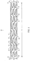
- Figure 1 shows one embodiment of a stent 10 in side elevation view, with a first expansion column 29, a second expansion column 30, a third expansion column31, a first connecting strut column 32, and a second connecting strut column 33.
- the stent 10 has a proximal end20 and a distal end 22.
- the stent 10 has a tubular or cylindrical structure.
- the stent 10 has a longitudinal length 24 and a longitudinal axis 26.
- an expansion column can be a zigzag or corrugated ring configuration of expansion struts.
- An expansion column, for example expansion column30, in a stent 10 can be an unbroken circular ring.
- Multiple expansion strut columns can be interconnected with connecting struts continuously along the longitudinal axis 26 of the stent 10 in an unbroken manner to form a stent 10 having a tubular shape.
- the interconnections among expansion columns and connecting strut columns enclose spaces, or cells, formed by expansion struts and connecting struts. In the embodiment shown in Figure 1, all cells have asymmetrical geometry.
- the stent 10 has two different diameters, including an outer diameter 36 and an inner diameter38, having a difference of a thickness of the stent 10. Both the outer diameter 36 and inner diameter 38 can change as the stent 10 goes through a crimping stage, when the diameters 36 and38 are narrowed, and through a deployed stage, when the diameters 36 and 38 are expanded.
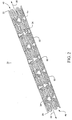
- Figure 2 shows one embodiment of a stent 10 in isometric view.
- a back half of the stent 10 can be seen through the cell space of the front half of the stent 10.
- the shown embodiment of the stent 10 has a tubular structure with a central lumen, a proximal opening 40, and a distal opening 42.
- Stent cells 34 include open spaces in the network of expansion struts and connecting struts.
- the lumen includes the central, open tunnel formed by the expansion and connecting struts of the stent.
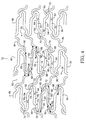
- FIG. 3 shows one embodiment of a stent 10 in cut-open 2-dimensional view.
- the stent 10 has a proximal end 20 and a distal end 22.
- This view of the stent 10 is a scale drawing for a 15 mm coronary stent.
- At the proximal end 20 is an expansion column 44, which is a mirror image of an expansion columns 46 at the distal end 22.
- there are six expansion columns such that an expansion column 49 alternates with an expansion column 48.
- connecting strut columns Interconnecting with eight expansion columns along the longitudinal axis 26 of the stent 10 are seven connecting strut columns including four connecting strut columns 94 and three connecting strut columns 92, such that a connecting strut column 94 alternates with a connecting strut column 92.
- Expansion columns 44,46, 48, and 49 are vertically arranged with expansion strut pair loops aligned peak to-valley. Connecting strut columns 92 and 94 interconnect expansion columns 44,46,48, and 49 in a continuous and unbroken manner along the length 24 and around the circumference 28 of the stent 10.
- the stent 10 in Figure 3 has the proximal end 20 on the left and the distal end 22 on the right.
- the stent 10 has a length 24 horizontally and a circumference28 vertically, with a longitudinal axis 26 horizontally along the length 24 from the proximal end 20 to the distal end 22.
- a width (horizontal dimension) of expansion columns is wider than a width of connecting strut columns.
- a width of a connecting strut column could be made the same or larger than a width of an expansion column.
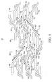
- one type of expansion column includes various expansion strut pairs.
- a joining strut section at a proximal end conjoins an expansion strut with short stepped-down section at a proximal end and an expansion strut with a short stepped-down section at a distal end, forming an expansion strut pair loop.
- a joining strut section at a distal end conjoins an expansion strut with a short stepped-down section at a distal end and an expansion strut with a short stepped-down section at a proximal end, forming an expansion strut pair loop.
- Figure 4 shows an embodiment having this type of expansion column 48.
- a joining strut section 70 at a proximal end conjoins an expansion strut 52 with a short stepped-down section at a proximal end and an expansion strut 54 with a short stepped-down section at a distal end forming an expansion strut pair loop.
- a joining strut section 72 at a distal end conjoins an expansion strut 54 with a short stepped-down section at a distal end 62 and an expansion strut 52 with a short stepped-down section at a proximal end 60, forming an expansion strut pair loop.
- a joining strut section at a proximal end conjoins an expansion strut with a short stepped-up section at a proximal end and an expansion strut with a short stepped-up section at a distal end, forming an expansion strut pair loop.
- a joining strut section at a distal end conjoins an expansion strut with a short stepped-up section at a distal end and an expansion strut with a short stepped-up section at a proximal end, forming an expansion strut pair loop.
- FIG. 4 shows an embodiment having this type of expansion column 49.
- a joining strut section 70 at a proximal end conjoins an expansion strut 56 with a short stepped-up section at a proximal end 66 and an expansion strut 58 with a short stepped-up section at a distal end 68, forming an expansion strut pair loop.
- a joining strut section 72 at a distal end can join an expansion strut 58 with a short stepped-up section at a distal end 68 and an expansion strut 56 with a short stepped-up section at a proximal end 66, forming an expansion strut pair loop.
- proximal and distal expansion strut pairs alternate, for example for six cycles, around the expansion ring without a break.
- a transitional slope 74 can be between a stepped down proximal section 60 and a straight section 64 in a stair step expansion strut 52.
- a transitional slope 76 can be between a stepped down distal section 62 and a straight section 64 in a stair step expansion strut 54.
- a transitional slope 78 can be between a stepped up proximal section 66 and a straight section 64 in a stair step expansion strut 56.
- a transitional slope 79 can be between a stepped up distal section 68 and a straight section 64 in a stair step expansion strut58.
- Figure 5 shows an example of connecting strut column 92 and connecting strut column 94.
- Connecting struts can have a curvilinear double stair step shape with a longitudinal axis is tilted to one side or the other side from the vertical plane, due to the diagonal orientation of connecting struts.
- Connecting struts of different connecting strut columns can have different longitudinal axes, which can be mirror images.
- longitudinal axis 120 for connecting struts in connecting strut column 92 is different from longitudinal axis 122 for connecting struts in connecting strut column 94.
- a connecting strut has three segments, two endstem sections and four pivot points.
- Figure 5 shows connecting struts with a proximal curvilinear segment 104, central segment 108, distal curvilinear segment 106, proximal end-stem 100, distal end-stem 102, and pivot points 112, 114,116, and 118.
- Pivot point 112 is a junction between proximal end-stem 100 and proximal curvilinear segment 104
- pivot point 114 is a junction between proximal curvilinear segment 104 and central segment 108
- pivot point 116 is a junction between central intermediate segment 108 and distal curvilinear segment 106
- pivot point118 is a junction between distal curvilinear segment 106 and distal end-stem 102.
- These pivot points can have a varying degree of radius of curvature. These multiple pivot points are responsible for flexibility of the stent and for prevention of foreshortening of the stent.
- a connecting strut in connecting strut column 92 has a proximal end 96 conjoined to an expansion strut in one expansion column, and a distal end 98 conjoined to an expansion strut in another expansion column.
- Proximal end 96 and distal end 98 of the connecting strut are conjoined to contralateral sides of apposing expansion strut pairs of adjacent expansion columns, at a stepped down or a stepped up sections.
- connecting strut Conjoining a connecting strut on contralateral sides, along with a diagonal orientation and multiple pivot points of the connecting strut provides good stent performance characteristics.
- the connecting strut can link two apposing expansion strut pairs in a diagonal orientation.
- a diagonal orientation of a connecting strut of the stent gives added flexibility, excellent crimping, vessel conformability and smooth surface modulation to the stent.
Abstract
Description
- This invention relates to intravascular stents in general, and more particularly to intracoronary stents.
- Intracoronary stents provide intraluminal scaffolding support of the vascular wall after percutaneous angioplasty in which the balloon catheter is used to expand the stenotic vascular lesion. In both the delivery phase and the deployed phase, there are numerous performance factors that can characterize the overall clinical performance of a stent and can be improved.
- By the year 2000, the percutaneous balloon angioplasty and stent implant procedures have become the dominant non-surgical revascularization method of the atherosclerotic stenosis, or obstruction, of the vascular lumen, and particularly in the coronary vascular system of the heart. With balloon angioplasty alone and without stents, the restenosis rate after angioplasty has been as high as 25-45% in the first time coronary cases. With stents after balloon angioplasty, the restenosis rate has been reduced significantly. Even so, the restenosis rate after stent implantation is reported to be 15-25% range in coronary arteries, depending on the condition of the stented vessel or the specific stent. An ideal coronary stent is still elusive in the current state of the art commercial products.
- Some of the best selling current, second generation, stents can be divided into two categories. One category is a stent with high flexibility and the other category has full vessel coverage. The flexible stents generally have poor vessel coverage, tissue prolapse, rough surface modulation and increased restenosis rate. On the other hand, a stent with good vessel coverage in the current state of art may not be flexible enough for easy delivery and for highly efficient procedures. This means that a stent with good flexibility and good vessel coverage remains as the unfulfilled gold standard.
- To further reduce the restenosis rate after stent implant, numerous means have been tried including laser, atherectomy, high frequency ultrasound, radiation device, local drug delivery, etc. Although the brachytherapy (radiation treatment) has proved to be reasonably effective in further reducing restenosis after stent implant, using brachytherpy is very cumbersome, inconvenient, and costly. Brachytherapy is a radioactive device and a radiation therapy specialist from another department has to be involved with the interventional cardiologist in the cardiac catheterization laboratory. The laser and atherectomy devices proved to be marginally useful with added costs.
- Local drug therapy appears to be a very promising method for the future, as better pharmaceutical, chemical, or biogenetic agents are developed and became available. Some research data, both from animal tests and human clinical studies indicate evidence of some suppression of restenosis after stent implantation when certain growth blocking pharmaceutical agents coat the stent.
- In other instances, it has been speculated that certain surface modifying materials coated on the surface of the stent may be beneficial, alone or in combination with growth suppressing agents, in reducing the restenosis rate. In either instance, a drug or substance should be locally attached or coated on the stent in sufficient amounts. However, attaching or coating a sufficient amount of a substance or drug on the coronary stent may not be an easy proposition, because coating enough volume of the drug on the small surface area of a stent is a challenging task. If and when stent coating becomes practical, a good stent can still have better outcomes than a poorly designed stent when used with substance coating.
- A stent is a scaffolding device. When delivered to a remote vessel location via percutaneous approach it can be deployed by expanding the device inside a vessel. The vessel can have a very small caliber and sometimes has a very tortuous anatomy. When a stent is deployed, the stent should have a good radial strength, good vessel coverage, a good internal surface modulation without tulips (i. e., sharp metal loop projections that resemble fish scale phenomena), optimal vesselconformability, a low metal fraction, and so forth.
- If the stent is stiff and non-flexible, it can be very difficult to deliver to an intended lesion site inside a vessel. Easy delivery of a stent is aided by good flexibility of the stent in combination with the delivery balloon, a smooth surface modulation without or minimizing tulips and a degree of radiopacity. A good stent should have a combination of features for delivery and deployment.
- Although there are countless variations of vascular stent designs today, few have these desired stent features both in the delivery phase and in the postdelivery phase. Today's top selling stents in the market can have undesirable characteristics, either in the delivery phase or in the deployed phase of the stent life cycle. For example, some stents may have flexibility, but lack vessel coverage or surface modulations both in delivery and deployed phases. Some stents may have good vessel coverage and surface modulations, but lack flexibility.
- Vascular stents, which are designed to be delivered to vessel sites via percutaneous approach, can have two elements. The first element is the expansion strut that expands circumferentially to provide the scaffolding radial force against a possible collapsing force of the vessel wall. The second element is the connecting strut that can link the expansion struts along the longitudinal axis of the stent, giving articulation or flexibility to the stent. The particular combination of expansion struts and connecting struts generally form various cells, depending on the specific configuration and shape of the expansion and connecting struts. If a cell is too large, the vessel wall support or coverage can be poor and the vessel wall tissue can prolapse through the large cells of the stent net. If the cells are too small, the vessel wall may be well covered but the metal fraction of the stent can be too high. The metal fraction is a fraction of the total metal surface area of an expanded stent (inside a blood vessel) divided by the total internal vessel wall surface area where the stent is deployed.
- Some very flexible stents have very large cell size with poor vessel coverage and tissue prolapse, in addition to poor(inner and/or outer) surface modulation due to large numbers of tulips directed to both ends of the stent.
- Most of the current flexible stents are designed to effect flexibility by using fewer or a minimal number of connecting struts, handicapping the vessel coverage, surface modulation and tissue prolapse defects.
- On the other hand, a stent that is designed for good vessel coverage and ideal cell size tends to be inflexible when such a stent is being delivered to a vessel lesion. A lack of flexibility during stent delivery is a very critical issue; a stiff stent often cannot be delivered to a needed location inside a blood vessel because such a stent cannot navigate through a tortuous and small vessel lumen.
- There is a need for a vascular stent that is very flexible for delivery and with good vessel coverage when deployed.
- Various embodiments of a stent include a combination of maximum possible flexibility and conformability in the stent, full vessel coverage with optimal metal fraction, evenly expanding stent struts, excellent radial strength and radiopacity, and smooth surface modulations in both delivery and deployed phases of the stent life cycle. To arrive at these goals, many detailed new innovations are added to the expansion and connecting strut designs of the stent.
- Expansion strut design is largely responsible for radial strength and radiopacity, while connecting strut design is largely responsible for flexibility and smooth surface modulations. Full vessel coverage and uniform stent expansion are largely from interaction between expansion and connecting struts. Various embodiments of the stent demonstrate a balance among these multiple qualities, using smart expansion struts and flexible connecting struts in a seamlessly integrated stent network.
- Various embodiments of the stent are specifically designed to be both very flexible and fully cover vessel surface inside the vascular lumen. The stent can have both characteristics of vessel coverage and flexibility, particularly for coronary use.
- Various embodiments of a stent are well designed for both the delivery phase and the deployed phase of the stent life cycle. Both flexibility and good vessel coverage are in a right balance in various embodiments of the stent have.
- Various embodiments of the stent include certain configurations in expansion and connecting struts of the stent.
- Some embodiments of the stent include a first expansion column, a second expansion column, and a first connecting strut column. The first expansion column and the second expansion column can each include individual expansion struts forming a plurality of expansion strut pairs. Two adjacent expansion strut pairs can share a common strut. The first connecting strut column can include a plurality of individual first connecting struts that couple the first and second expansion columns. Each connecting strut can include a curvilinear proximal section and a curvilinear distal section.
- Some embodiments of the stent include a first expansion column, a second expansion column, and a first connecting strut. The first expansion column and the second expansion column can include expansion struts forming a plurality of expansion strut pair loops. Expansion strut pair loops can couple adjacent expansion struts. Two adjacent expansion struts can share a common strut. The first connecting strut column can include a plurality of individual connecting struts. Each connecting strut can have a proximal section and a distal section. Each connecting strut can have a stair-step geometric configuration with a curvilinear proximal section and a curvilinear distal section.
-
- Figure 1 shows a side elevation view of an embodiment of a stent, such as a tubular stent.
- Figure 2 shows an isometric view of an embodiment of a stent, such as a tubular stent.
- Figure 3 shows a cut-open view of an embodiment of a stent. Various expansion columns and connecting strut columns are shown.
- Figure 4 shows a magnified view of a middle section of an embodiment of a stent, such as a stent of Figures1, 2, and 3. Some details are shown of expansion columns.
- Figure 5 shows a magnified view of a middle section of an embodiment of a stent, such as a stent of Figures 1,2, and 3. Some details are shown of connecting strut columns.
- Some embodiments of stents can be in a state, such as one or more of a non-expanded state, an expanded state, a crimped state, and a non-crimped state.
- Some embodiments of stents can include one or more of a first expansion column, a second expansion column, a third expansion column, a first connecting strut column, and a second connecting strut column.
- Figure 1 shows an embodiment having a
first expansion column 29, a second expansion column30, a third expansion column31, a first connectingstrut column 32, and a second connectingstrut column 33. The first expansion column, the second expansion column, and the third expansion column can include individual expansion struts forming a plurality of expansion strut pairs. - In many embodiments of the stent, two adjacent expansion strut pairs share a common strut.
- The first connecting strut column and the second connecting strut column include a plurality of individual connecting struts. Each connecting strut has a stair-step geometric configuration with a curvilinear proximal section and a curvilinear distal section. The first connecting strut column can include individual first connecting struts and the second connecting strut column can include individual second connecting struts. The first connecting column couples the first and second expansion columns. Figure 1 shows an example where the first connecting
column 32 couples thefirst expansion column 29 and thesecond expansion column 30. The second connectingcolumn 33 couples thesecond expansion column 30 and the third expansion column31. - Each expansion strut can have a stair-step configuration. Distal ends of expansion strut pairs of the first expansion column that are coupled to proximal ends of expansion strut pairs of the second expansion column can be vertically offset. Distal ends of expansion strut pairs of the second expansion column that are coupled to proximal ends of expansion strut pairs of the third expansion column can also be vertically offset.
- Some embodiments of the stent include connecting struts with five sections, including an intermediate section, a proximal curvilinear section and a distal curvilinear section. The proximal section of each first connecting strut can be contralaterally conjoined to an expansion strut pair of the first expansion column. The distal section can be contralaterally conjoined to an expansion strut pair of the second expansion column. The proximal and distal sections can have the same lengths.
- At least a portion of the proximal and distal curvilinear section can be parallel to a portion of an expansion strut pair loop in the first expansion column or in the second expansion column.
- The proximal section can include a terminal end conjoined to an expansion strut in the first expansion column, and at least one surface that is conjoined to at least one surface of an expansion strut in the first expansion column. The distal section includes a terminal end conjoined to an expansion strut in the second expansion column, and at least one surface that is conjoined to an expansion strut in the second expansion column.
- At least one of the proximal and distal sections of each connecting strut can be contralaterally conjoined to an expansion strut pair of the first and second expansion columns, or to an expansion pair of the second and third expansion columns.
- At least a portion of the curvilinear proximal section of each connecting strut can be parallel to a portion of an expansion strut pair loop. At least a portion of the curvilinear distal section of each connecting strut can be parallel to a portion of an expansion strut pair loop of an expansion column.
- At least a portion of the curvilinear proximal section of each connecting strut can be positioned in close proximity to an expansion strut pair loop of an expansion column. At least a portion of the curvilinear distal section of each connecting strut can be positioned in close proximity to an expansion strut pair loop. Close proximity can be in the range of 0.001 to 0.050 of an inch, in the range of 0.001 to 0.040 of an inch, or in the range of 0.001 to 0.030 of an inch.
- In various embodiments of the stent each connecting strut can have a proximal end, a distal end, four pivot points, and a longitudinal axis. The proximal end can extend in a first direction. The distal end of a connecting strut can extend in an second direction opposite to the first direction.
- Each connecting strut in the first connecting strut column has two radii of curvature each with the proximal and distal curvilinear section. Figure 5 shows examples pivot
points points - The longitudinal axis of the connecting strut may be non-parallel to a longitudinal axis of the stent. In some embodiments of the stent, each connecting strut in a same connecting strut column can share the similar longitudinal axis, which can be mutually parallel.
- Each first connecting strut can have a longitudinal axis that extends in a first direction. Each second connecting strut can have a longitudinal axis that extends in an opposite second direction.
- The intermediate section can have a longitudinal axis. The longitudinal axis of an intermediate section may be parallel to an expansion strut in the first expansion column, parallel to an expansion strut in the second expansion column, non-parallel to the longitudinal axis of the first connecting strut, and parallel to the longitudinal axis of the stent. The intermediate section is coupled to the curvilinear proximal section and the curvilinear distal section.
- Each connecting strut is contralaterally conjoined to the first and second expansion columns. At least a portion of the connecting struts can have asymmetrical geometric configurations.
- Some embodiments of the stent include a first end expansion column and a second end expansion column. The first and second end expansion columns can define a proximal and a distal end of the stent, and are mirror images of each other.
- A plurality of cells can be defined by the first expansion column, the second expansion column and the first connecting strut column. Cells can have evenly spaced, asymmetrical geometric shapes. Cells can also have evenly spaced geometric shapes with a quasi-hexagonal geometry in a nominally expanded state.
- Expansion strut pair loops in two adjacent expansion columns can be aligned in a peak-to-valley, in a valley-to-peak geometry, or in a peak-to-peak geometry.
- An expansion column includes expansion struts that form expansion strut pairs in a ring shape. Each pair of expansion struts has two struts conjoined by a joining strut section at either a proximal or distal end. This pairing between two adjacent expansion struts conjoined by a joining strut section alternates from proximal to distal and distal to proximal. This sequence, in one embodiment, can continue twelve times seamlessly around the circumference of a ring for six zigzag cycles around the circumference of the ring shape. In such an embodiment there are twelve expansion strut pairs in alternating positions in an expansion column. There can also be twelve joining strut sections, six in a proximal end and six in a distal end in an alternating sequence. Expansion struts can include one or more of a short stepped-down segment at a proximal end, a short stepped-down segment at a distal end, a short stepped-up segment at a proximal end, and a short stepped-up segment at a distal end. Some embodiments of the stent include expansion struts with a short-sloped transitional segment between the long and short parts in the stair-step expansion struts. Various embodiments of the stent can include various combination of one or more of different expansion struts. At proximal or distal end of the stent, the terminating side of an end expansion column can have smooth and evenly rounded loops.
- Various embodiments of the stent include one or more types of expansion columns. A first expansion column includes various expansion strut pairs. A joining strut section at a proximal end can join an expansion strut with a short stepped-down section at a proximal end and an expansion strut with a short stepped-down section at a distal end, forming an expansion strut pair loop.
- A joining strut section at a distal end can join an expansion strut with a short stepped-down section at a distal end and an expansion strut with a short stepped-down section at a proximal end, forming an expansion strut pair loop.
- These expansion strut pairs alternate, for example for six cycles, around the expansion ring without a break.
- A second expansion column includes various expansion strut pairs. A joining strut section at a proximal end can join an expansion strut with a short stepped-up section at a proximal end and an expansion strut with a short stepped-up section at a distal end, forming an expansion strut pair loop. A joining strut section at a distal end can join an expansion strut with a short stepped-up section at a distal end and an expansion strut with a short stepped-up section at a proximal end, forming an expansion strut pair loop. These expansion strut pairs alternate, for example for six cycles, around the expansion ring without a break.
- Different types of expansion columns can be arranged in an alternating sequence, inter-linked along the length of the stent by connecting columns.
- Stepped-up or stepped-down segments with a sloped transitional section can provide flexibility, smooth surface modulation effects, and well-formed crimping space to the stent. A connecting strut can conjoin with an expansion strut pair at a short stepped-down or stepped-up section of an expansion strut. A connecting strut can be a direct extension of an expansion strut and be integral to the stent structure rather than a separate structure added, welded, or attached.
- Separate terminology for stent elements, for example expansion and connecting struts, conveniently describing the anatomy and function of various stent portions.
- Connecting struts can have a curvilinear double stair step shape with a longitudinal axis diagonally tilted to one side or the other side from the vertical, due to the diagonal orientation. Connecting struts of different connecting strut columns can have different longitudinal axes, which can be mirror images. In some embodiments of the stent, a connecting strut has three segments, two endstem sections and four pivot points. Pivot points can have a varying radius of curvature. These multiple pivot points are responsible for flexibility. One end of a connecting strut can conjoin with an expansion strut pair in one expansion strut column and another end of the connecting strut can conjoin to another expansion strut pair in an adjacent expansion strut column. The connecting strut can link two apposing expansion strut pairs in a diagonal orientation. A diagonal orientation of a connecting strut of the stent gives added flexibility, excellent crimping, vessel conformability and smooth surface modulation to the stent.
- Further, when a connecting strut conjoins expansion strut pairs, both ends of a connecting strut conjoin to the contralateral sides of apposing expansion strut pairs of adjacent expansion columns, at a stepped down or a stepped up sections. Conjoining a connecting strut on contralateral sides, along with a diagonal orientation and multiple pivot points, can provide good stent performance characteristics.
- In some embodiments of the stent, the ratio of expansion strut to connecting strut number is two to one, where such as when a connecting strut is conjoined to expansion strut pairs.
- When the expansion columns and connecting columns are conjoined, the stent can have a continuous, unbroken cylindrical form without breaks or delinking around the circumference and along the length of the stent. Unbroken links between the expansion and connecting struts can make regular and evenly spaced asymmetrical cells. The cell size can be maximized or minimized by programming of the stent design platform, as dictated by clinical or applications requirements.
- Figure 1 shows one embodiment of a
stent 10 in side elevation view, with afirst expansion column 29, asecond expansion column 30, a third expansion column31, a first connectingstrut column 32, and a second connectingstrut column 33. Thestent 10 has a proximal end20 and adistal end 22. Thestent 10 has a tubular or cylindrical structure. Thestent 10 has alongitudinal length 24 and alongitudinal axis 26. - In some embodiments of the stent, an expansion column can be a zigzag or corrugated ring configuration of expansion struts. An expansion column, for example expansion column30, in a
stent 10 can be an unbroken circular ring. - Multiple expansion strut columns can be interconnected with connecting struts continuously along the
longitudinal axis 26 of thestent 10 in an unbroken manner to form astent 10 having a tubular shape. The interconnections among expansion columns and connecting strut columns enclose spaces, or cells, formed by expansion struts and connecting struts. In the embodiment shown in Figure 1, all cells have asymmetrical geometry. Thestent 10 has two different diameters, including anouter diameter 36 and an inner diameter38, having a difference of a thickness of thestent 10. Both theouter diameter 36 andinner diameter 38 can change as thestent 10 goes through a crimping stage, when thediameters 36 and38 are narrowed, and through a deployed stage, when thediameters - Figure 2 shows one embodiment of a
stent 10 in isometric view. A back half of thestent 10 can be seen through the cell space of the front half of thestent 10. The shown embodiment of thestent 10 has a tubular structure with a central lumen, aproximal opening 40, and adistal opening 42.Stent cells 34 include open spaces in the network of expansion struts and connecting struts. - The lumen includes the central, open tunnel formed by the expansion and connecting struts of the stent.
- Figure 3 shows one embodiment of a
stent 10 in cut-open 2-dimensional view. Thestent 10 has aproximal end 20 and adistal end 22. This view of thestent 10 is a scale drawing for a 15 mm coronary stent. There are eight expansion columns and seven connecting strut columns. At theproximal end 20 is anexpansion column 44, which is a mirror image of anexpansion columns 46 at thedistal end 22. In the middle of thestent 10, there are six expansion columns, such that anexpansion column 49 alternates with anexpansion column 48. Interconnecting with eight expansion columns along thelongitudinal axis 26 of thestent 10 are seven connecting strut columns including four connectingstrut columns 94 and three connectingstrut columns 92, such that a connectingstrut column 94 alternates with a connectingstrut column 92. - There are a total of 42 cells of various asymmetric configurations. All the cells in this embodiment have asymmetrical geometry.
Expansion columns strut columns interconnect expansion columns length 24 and around thecircumference 28 of thestent 10. - The
stent 10 in Figure 3 has theproximal end 20 on the left and thedistal end 22 on the right. Thestent 10 has alength 24 horizontally and a circumference28 vertically, with alongitudinal axis 26 horizontally along thelength 24 from theproximal end 20 to thedistal end 22. - A width (horizontal dimension) of expansion columns is wider than a width of connecting strut columns. However, a width of a connecting strut column could be made the same or larger than a width of an expansion column.
- The variation of width ratio between a connecting strut column and an expansion column are within the scope of present invention of
stent 10. The number of expansion strut cycles in an expansion column and the number of connecting struts in a connecting strut column can be made variably different. - Variable numbers of making expansion strut cycles and connecting struts are within the scope of the present invention of the
stent 10. - In some embodiments of the stent, one type of expansion column includes various expansion strut pairs. A joining strut section at a proximal end conjoins an expansion strut with short stepped-down section at a proximal end and an expansion strut with a short stepped-down section at a distal end, forming an expansion strut pair loop. A joining strut section at a distal end conjoins an expansion strut with a short stepped-down section at a distal end and an expansion strut with a short stepped-down section at a proximal end, forming an expansion strut pair loop. These expansion strut pairs alternate, for example for six cycles, around the expansion ring without a break.
- Figure 4 shows an embodiment having this type of
expansion column 48. A joiningstrut section 70 at a proximal end conjoins anexpansion strut 52 with a short stepped-down section at a proximal end and anexpansion strut 54 with a short stepped-down section at a distal end forming an expansion strut pair loop. A joiningstrut section 72 at a distal end conjoins anexpansion strut 54 with a short stepped-down section at adistal end 62 and anexpansion strut 52 with a short stepped-down section at aproximal end 60, forming an expansion strut pair loop. - Another type of expansion column includes various expansion strut pair combinations. A joining strut section at a proximal end conjoins an expansion strut with a short stepped-up section at a proximal end and an expansion strut with a short stepped-up section at a distal end, forming an expansion strut pair loop. A joining strut section at a distal end conjoins an expansion strut with a short stepped-up section at a distal end and an expansion strut with a short stepped-up section at a proximal end, forming an expansion strut pair loop.
- Figure 4 shows an embodiment having this type of
expansion column 49. A joiningstrut section 70 at a proximal end conjoins anexpansion strut 56 with a short stepped-up section at aproximal end 66 and anexpansion strut 58 with a short stepped-up section at adistal end 68, forming an expansion strut pair loop. A joiningstrut section 72 at a distal end can join anexpansion strut 58 with a short stepped-up section at adistal end 68 and anexpansion strut 56 with a short stepped-up section at aproximal end 66, forming an expansion strut pair loop. - These proximal and distal expansion strut pairs alternate, for example for six cycles, around the expansion ring without a break.
- A transitional slope 74 can be between a stepped down
proximal section 60 and astraight section 64 in a stairstep expansion strut 52. Likewise, atransitional slope 76 can be between a stepped downdistal section 62 and astraight section 64 in a stairstep expansion strut 54. Atransitional slope 78 can be between a stepped upproximal section 66 and astraight section 64 in a stairstep expansion strut 56. Likewise, atransitional slope 79 can be between a stepped updistal section 68 and astraight section 64 in a stair step expansion strut58. - Figure 5 shows an example of connecting
strut column 92 and connectingstrut column 94. Connecting struts can have a curvilinear double stair step shape with a longitudinal axis is tilted to one side or the other side from the vertical plane, due to the diagonal orientation of connecting struts. - Connecting struts of different connecting strut columns can have different longitudinal axes, which can be mirror images. For example,
longitudinal axis 120 for connecting struts in connectingstrut column 92 is different fromlongitudinal axis 122 for connecting struts in connectingstrut column 94. In some embodiments of the stent, a connecting strut has three segments, two endstem sections and four pivot points. Figure 5 shows connecting struts with a proximalcurvilinear segment 104,central segment 108, distalcurvilinear segment 106, proximal end-stem 100, distal end-stem 102, and pivotpoints 112, 114,116, and 118.Pivot point 112 is a junction between proximal end-stem 100 and proximalcurvilinear segment 104,pivot point 114 is a junction between proximalcurvilinear segment 104 andcentral segment 108,pivot point 116 is a junction between centralintermediate segment 108 and distalcurvilinear segment 106, and pivot point118 is a junction between distalcurvilinear segment 106 and distal end-stem 102. These pivot points can have a varying degree of radius of curvature. These multiple pivot points are responsible for flexibility of the stent and for prevention of foreshortening of the stent. One end of a connecting strut can conjoin with an expansion strut pair in one expansion strut column and another end of the connecting strut can conjoin to another expansion strut pair in an adjacent expansion strut column. For example, a connecting strut in connectingstrut column 92 has aproximal end 96 conjoined to an expansion strut in one expansion column, and adistal end 98 conjoined to an expansion strut in another expansion column.Proximal end 96 anddistal end 98 of the connecting strut are conjoined to contralateral sides of apposing expansion strut pairs of adjacent expansion columns, at a stepped down or a stepped up sections. Conjoining a connecting strut on contralateral sides, along with a diagonal orientation and multiple pivot points of the connecting strut provides good stent performance characteristics. The connecting strut can link two apposing expansion strut pairs in a diagonal orientation. A diagonal orientation of a connecting strut of the stent gives added flexibility, excellent crimping, vessel conformability and smooth surface modulation to the stent. - Some examples of stents are listed below:
- 1. A stent in a non-expanded state, comprising: a first expansion column including individual expansion struts forming a plurality of expansion strut pairs, wherein two adjacent expansion strut pairs share a common strut; a second expansion column including individual expansion struts forming a plurality of expansion strut pairs, wherein two adjacent expansion strut pairs share a common strut ; a first connecting strut column including a plurality of individual first connecting struts that couple the first and second expansion columns, wherein each of a first connecting strut in the first connecting strut column has a stair-step geometric configuration with a curvilinear proximal section and a curvilinear distal section.
- 2. The stent of clause 1, wherein each first connecting strut in a first connecting column has at least one curvilinear configuration in one of its proximal and distal sections.
- 3. The stent of clause 1, wherein at least one of the proximal and distal sections of each first connecting strut in the first connecting strut column is contralaterally conjoined to an expansion strut pair of the first and second expansion columns.
- 4. The stent of clause 1, wherein the proximal section of each first connecting strut in the first connecting strut column is contralaterally conjoined to an expansion strut pair of the first expansion column and its corresponding distal section is contralaterally conjoined to an expansion strut pair of the second expansion column.
- 5. The stent of clause 1, wherein each first connecting strut in the first connecting strut column has a proximal end that extends in a first direction and a distal end that extends in an opposite second direction.
- 6. The stent of clause 1, wherein each first connecting strut in the first connecting strut column has five sections.
- 7. The stent of clause 1, wherein each first connecting strut in the first connecting strut column has four pivot points.
- 8. The stent of clause 7, wherein each pivot point has at least one radius of curvature.
- 9. The stent of clause 1, wherein each first connecting strut in the first connecting strut column has an intermediate section coupled to the curvilinear proximal section and the curvilinear distal section.
- 10. The stent of clause, wherein each first connecting strut in the first connecting strut column has a longitudinal axis that is non-parallel to a longitudinal axis of the stent
- 11. The stent of
clause 9, wherein each intermediate section of each first connecting strut of the first connecting strut column has a longitudinal axis that is non-parallel to the longitudinal axis of the first connecting strut. - 12. The stent of clause 11, wherein each longitudinal axis of each intermediate section of each first connecting strut in the first connecting strut column is parallel to the longitudinal axis of the stent.
- 13. The stent of
clause 10, wherein each first connecting strut in the first connecting strut column has the same longitudinal axis. - 14. The stent of
clause 10, wherein all of the first connecting struts in the first connecting strut column have parallel longitudinal axes. - 15. The stent of clause 1, wherein each expansion strut in each expansion strut pair of the first and second expansion columns has a stair-step configuration.
- 16. The stent of clause 1, wherein one expansion strut of an expansion strut pair of the first expansion column has a stair-step segment at a proximal section and the other expansion strut of the expansion strut pair has a stair-step segment at a distal section.
- 17. The stent of clause 16, wherein one expansion strut of an expansion strut pair of the second expansion column has a stair-step segment at a distal section and the other expansion strut of the expansion strut pair has a stair-step segment at a proximal section.
- 18. The stent of clause 1, wherein at least a portion of the first connecting struts of the first connecting strut column have asymmetrical geometric configurations.
- 19. The stent of clause 1, wherein a terminal end of the proximal section of each first connecting strut in the first connecting column is conjoined to an expansion strut in the first expansion column, and a terminal end of the distal section of each first connecting strut is conjoined to an expansion strut in the second expansion column.
- 20. The stent of clause 1, wherein the proximal section of each first connecting strut has a surface that is conjoined to at least one surface of an expansion strut in the first expansion column, and the distal section of each first connecting strut has at least one surface that is conjoined to an expansion strut in the second expansion column.
- 21. The stent of clause 1, wherein the proximal and distal sections of each first connecting strut of the first connecting strut column have the same lengths.
- 22. The stent of clause 1, wherein each first connecting strut of the first connecting column is contralaterally conjoined to the first and second expansion columns.
- 23. The stent of clause 1, wherein at least a portion of the curvilinear proximal section of each first connecting strut of the first connecting strut column is in close proximity to an expansion strut pair of the first expansion column.
- 24. The stent of clause 1, wherein at least a portion of the curvilinear proximal section of each first connecting strut of the first connecting strut column is parallel to a portion of an expansion strut pair of the first expansion column.
- 25. The stent of
clause 24, wherein at least a portion of the curvilinear distal section of each first connecting strut of the first connecting strut column is in close proximity to an expansion strut pair of the second expansion column. - 26. The stent of clause 1, wherein at least a portion of the curvilinear distal section of each first connecting strut of the first connecting strut column is parallel to a portion of an expansion strut pair of the second expansion column.
- 27. The stent of clause 25, wherein close proximity is in the range of 0.001 to 0.050 of an inch.
- 28. The stent of clause 1, wherein distal ends of expansion strut pairs of the first expansion column that are coupled to proximal ends of expansion strut pairs of the second expansion column are vertically offset.
- 29. The stent of clause 1, further comprising: a plurality of expansion columns coupled by a plurality of connecting strut columns
- 30. The stent of
clause 29, further comprising: a first end expansion column and a second end expansion column. - 31. The stent of
clause 30, wherein the first and second end expansion columns define a proximal and a distal end of the stent. - 32. The stent of
clause 30, wherein the first and second end expansion columns are mirror images of each other. - 33. The stent of clause 1, wherein the first expansion column, the second expansion column and the first connecting strut column define a plurality of cells.
- 34. The stent of
clause 33, wherein the plurality of cells have asymmetrical geometries. - 35. The stent of
clause 33, wherein the plurality of cells have evenly spaced geometric shapes. - 36. The stent of
clause 33, wherein the plurality of cells have a quasi-hexagonal geometry in a nominally expanded state. - 37. The stent of clause 1, further comprising: a third expansion column including individual expansion struts forming a plurality of expansion strut pairs, wherein two adjacent expansion strut pairs share a common strut; a second connecting strut column including a plurality of individual second connecting struts that couple the second and third expansion columns, wherein each of a second connecting strut in the second connecting strut column has a stair-step geometric configuration with a curvilinear proximal section and a curvilinear distal section.
- 38. The stent of clause 37, wherein each first connecting strut of the first connecting strut column has a longitudinal axis that extends in a first direction, and each second connecting strut of the second connecting strut column has a longitudinal axis that extends in an opposite second direction.
- 39. The stent of clause 37, wherein distal ends of expansion strut pairs of the second expansion column that are coupled to proximal ends of expansion strut pairs of the third expansion column are vertically offset.
- 40. A stent in a non-expanded state, comprising: a first expansion column including individual expansion struts forming a plurality of expansion strut pair loops that couple adjacent individual expansion struts, wherein two adjacent expansion struts share a common strut; a second expansion column including individual expansion struts forming a plurality of expansion strut pair loops that couple adjacent individual expansion struts, wherein two adjacent expansion struts share a common strut ; and a first connecting strut column including a plurality of individual connecting struts, wherein each of a first connecting strut in the first connecting strut column has a stair-step geometric configuration with a curvilinear proximal section and a curvilinear distal section.
- 41. The stent of
clause 40, wherein at least a portion of the expansion strut pair loops have a radius of curvature. - 42. The stent of
clause 40, wherein at least a portion of the curvilinear proximal section of each first connecting strut of the first connecting strut column is parallel to at least a portion of the radius of curvature of an expansion strut pair loop in the first expansion column. - 43. The stent of
clause 40, wherein at least a portion of the curvilinear distal section of each first connecting strut of the first connecting strut column is parallels to at least a portion of the radius of curvature of an expansion strut pair loop in the second expansion column. - 44. The stent of
clause 40, wherein at least one of the proximal and distal curvilinear sections of each first connecting strut of the first connecting strut column is parallel to at least a portion of the radius of curvature of one of the expansion strut pair loops in the first and second expansion columns. - 45. The stent of
clause 40, wherein at least one of the proximal and distal sections of each first connecting strut in the first connecting strut column is contralaterally conjoined to an expansion strut pair of the first and second expansion columns. - 46. The stent of
clause 40, wherein the proximal section of each first connecting strut in the first connecting strut column is contralaterally conjoined to an expansion strut pair of the first expansion column and its corresponding distal section is contralaterally conjoined to an expansion strut pair of the second expansion column. - 47. The stent of
clause 40, wherein each first connecting strut in the first connecting strut column has a proximal end that extends in a first direction and a distal end that extends in an opposite second direction. - 48. The stent of
clause 40, wherein each first connecting strut in the first connecting strut column has five sections. - 49. The stent of
clause 40, wherein each first connecting strut in the first connecting strut column has four pivot points. - 50. The stent of
clause 49, wherein each pivot point has at least one radius of curvature. - 51. The stent of
clause 40, wherein each first connecting strut in the first connecting strut column has an intermediate section coupled to the curvilinear proximal section and the curvilinear distal section. - 52. The stent of clause 51, wherein each first connecting strut in the first connecting strut column has a longitudinal axis that is non-parallel to a longitudinal axis of the stent.
- 53. The stent of
clause 52, wherein each intermediate section of each first connecting strut of the first connecting strut column has a longitudinal axis that is non-parallel to the longitudinal axis of the first connecting strut. - 54. The stent of
clause 52, wherein each first connecting strut in the first connecting strut column has the same longitudinal axis. - 55. The stent of
clause 52, wherein all of the first connecting struts in the first connecting strut column have parallel longitudinal axes. - 56. The stent of
clause 40, wherein each connecting strut in the first connecting strut column has at least two radii of curvature at its proximal section and at least two radii of curvature at its distal section. - 57. The stent of
clause 40, wherein each expansion strut in each expansion strut pair loop of the first and second expansion columns has a stair-step configuration. - 58. The stent of
clause 40, wherein one expansion strut of an expansion strut pair loop of the first expansion column has a stair-step segment at a proximal section and the other expansion strut of the expansion strut pair has a stair-step segment at a distal section. - 59. The stent of
clause 58, wherein one expansion strut of an expansion strut pair loop of the second expansion column has a stair-step segment at a distal section and the other expansion strut of the expansion strut pair has a stair-step segment at a proximal section. - 60. The stent of
clause 40, wherein at least at least a portion of the first connecting struts of the first connecting strut column have asymmetrical geometric configurations. - 61. The stent of
clause 40, wherein a terminal end of the proximal section of each first connecting strut in the first connecting column is conjoined to an expansion strut in the first expansion column, and a terminal end of the distal section of each first connecting strut is conjoined to an expansion strut in the second expansion column. - 62. The stent of
clause 40, wherein the proximal section of each first connecting strut has a surface that is conjoined to at least one surface of an expansion strut of an expansion strut pair loop in the first expansion column, and the distal section of each first connecting strut has at least one surface that is conjoined to an end of an expansion strut of an expansion strut pair loop in the second expansion column. - 63. The stent of
clause 40, wherein the proximal and distal sections of each first connecting strut of the first connecting strut column have the same lengths. - 64. The stent of
clause 40, wherein each first connecting strut of the first connecting column is contralaterally conjoined to the first and second expansion columns. - 65. The stent of
clause 40, wherein at least a portion of the proximal section of each first connecting strut of the first connecting strut column is in close proximity to an expansion strut pair of the first expansion column. - 66. The stent of clause 65, wherein at least a portion of distal section of each first connecting strut of the first connecting strut column is in close proximity to an expansion strut pair of the second expansion column.
- 67. The stent of clause 65, wherein close proximity is in the range of 0.001 to 0.050 of an inch.
- 68. The stent of
clause 40, wherein distal ends of expansion strut pair loops of the first expansion column that are coupled to proximal ends of expansion strut pairs of the second expansion column are vertically offset. - 69. The stent of
clause 40, further comprising: a plurality of expansion columns coupled by a plurality of connecting strut columns. - 70. The stent of clause 69, further comprising: a first end expansion column and a second end expansion column.
- 71. The stent of
clause 70, wherein the first and second end expansion columns define a proximal and a distal end of the stent. - 72. The stent of
clause 70, wherein the first and second end expansion columns are mirror images of each other. - 73. The stent of
clause 40, wherein the first expansion column, the second expansion column and the first connecting strut column define a plurality of cells. - 74. The stent of clause 73, wherein the plurality of cells have asymmetrical geometries.
- 75. The stent of clause 73, wherein the plurality of cells have evenly spaced geometric shapes with a quasi-hexagonal geometry in a nominally expanded state.
- 76. The stent of
clause 40, further comprising: a third expansion column including individual expansion struts forming a plurality of expansion strut pair loops that couple adjacent individual expansion struts, wherein two adjacent expansion struts share a common strut; and a second connecting strut column including a plurality of individual connecting struts each with a proximal section and a distal section, wherein each of a second connecting strut in the second connecting strut column has a stair-step geometric configuration with a curvilinear proximal section and a curvilinear distal section. - 77. The stent of
clause 76, wherein at least a portion of the expansion strut pair loops has a radius of curvature. - 78. The stent of
clause 76, wherein at least a portion of the curvilinear proximal section of each second connecting strut of the second connecting strut column is parallel to at least a portion of the radius of curvature of an expansion strut pair loop in the second expansion column. - 79. The stent of
clause 76, wherein at least a portion of the curvilinear distal section of each second connecting strut of the second connecting strut column is parallel to at least a portion of the radius of curvature of an expansion strut pair loop in the third expansion column. - 80. The stent of
clause 76, wherein at least one of the proximal and distal curvilinear sections of each second connecting strut of the second connecting strut column is parallel to at least a portion of the radius of curvature of one of the expansion strut pair loops in the first and second expansion columns. - 81. The stent of
clause 76, wherein at least a portion of the proximal section of each second connecting strut of the second connecting strut column is in close proximity to an expansion strut pair loop of the second expansion column. - 82. The stent of
clause 76, wherein at least a portion of the distal section of each second connecting strut of the second connecting strut column is in close proximity to an expansion strut pair loop of the second expansion column. - 83. The stent of clause 81, wherein close proximity is in the range of 0.001 to 0.050 of an inch.
- 84. The stent of
clause 76, wherein each first connecting strut of the first connecting strut column has a longitudinal axis that extends in a first direction, and each second connecting strut of the second connecting strut column has a longitudinal axis that extends in an opposite second direction. - 85. The stent of
clause 76, wherein distal ends of expansion strut pairs of the second expansion column that are coupled to proximal ends of expansion strut pairs of the third expansion column are vertically offset. - 86. The stent of
clause 76, wherein expansion strut pair loops of the second and third expansion columns are aligned in a peak-to-valley geometry. - 87. The stent of
clause 76, wherein expansion strut pair loops of the second and first expansion columns are aligned in a valley-to-peak geometry. - 88. The stent of
clause 76, wherein expansion strut pair loops of the second and third expansion columns are aligned in a peak-to-peak geometry. - 89. The stent of
clause 40, further comprising: a first end expansion column and a second end expansion column. - 90. The stent of
clause 89, wherein the first and second end expansion columns define a proximal and a distal end of the stent. - 91. The stent of
clause 89, wherein the first and second end expansion columns are mirror images of each other.
Claims (22)
- A stent in a non-expanded state, comprising: a first expansion column including individual expansion struts forming a plurality of expansion strut pairs, wherein two adjacent expansion strut pairs share a common strut, wherein one expansion strut of an expansion strut pair of the first expansion column has a stair-step segment at a proximal section and the other expansion strut of the expansion strut pair has a stair-step segment at a distal section; a second expansion column including individual expansion struts forming a plurality of expansion strut pairs, wherein two adjacent expansion strut pairs share a common strut, wherein one expansion strut of an expansion strut pair of the second expansion column has a stair-step segment at a proximal section and the other expansion strut of the expansion strut pair has a stair-step segment at a distal section; a first connecting strut column including a plurality of individual first connecting struts that couple the first and second expansion columns, wherein each of a first connecting strut in the first connecting strut column has a stair-step geometric configuration.
- The stent of claim 1, wherein each first connecting strut in a first connecting column has a curvilinear proximal section and a curvilinear distal section.
- The stent of claim 2, wherein at least one of the proximal and distal sections of each first connecting strut in the first connecting strut column is contralaterally conjoined to an expansion strut pair of the first and second expansion columns.
- The stent of claim 2, wherein the proximal section of each first connecting strut in the first connecting strut column is contralaterally conjoined to an expansion strut pair of the first expansion column and its corresponding distal section is contralaterally conjoined to an expansion strut pair of the second expansion column.
- The stent of claim 1, wherein each first connecting strut in the first connecting strut column has a proximal end that extends in a first direction and a distal end that extends in an opposite second direction.
- The stent of claim 1, wherein each first connecting strut in the first connecting strut column has four pivot points.
- The stent of claim 6, wherein each pivot point has at least one radius of curvature.
- The stent of claim 1, wherein each first connecting strut in the first connecting strut column has an intermediate section coupled to the curvilinear proximal section and the curvilinear distal section.
- The stent of claim 1, wherein each first connecting strut in the first connecting strut column has a longitudinal axis that is non-parallel to a longitudinal axis of the stent.
- The stent of claim 8, wherein each intermediate section of each first connecting strut of the first connecting strut column has a longitudinal axis that is non-parallel to the longitudinal axis of the first connecting strut.
- The stent of claim 10, wherein each longitudinal axis of each intermediate section of each first connecting strut in the first connecting strut column is parallel to the longitudinal axis of the stent.
- The stent of claim 9, wherein each first connecting strut in the first connecting strut column has the same longitudinal axis.
- The stent of claim 9, wherein all of the first connecting struts in the first connecting strut column have parallel longitudinal axes.
- The stent of claim 1, wherein at least a portion of the first connecting struts of the first connecting strut column have asymmetrical geometric configurations.
- The stent of claim 2, wherein a terminal end of the proximal section of each first connecting strut in the first connecting column is conjoined to an expansion strut in the first expansion column, and a terminal end of the distal section of each first connecting strut is conjoined to an expansion strut in the second expansion column.
- The stent of claim 2, wherein the proximal section of each first connecting strut has a surface that is conjoined to at least one surface of an expansion strut in the first expansion column, and the distal section of each first connecting strut has at least one surface that is conjoined to an expansion strut in the second expansion column.
- The stent of claim 2, wherein the proximal and distal sections of each first connecting strut of the first connecting strut column have the same lengths.
- The stent of claim 1, wherein each first connecting strut of the first connecting column is contralaterally conjoined to the first and second expansion columns.
- The stent of claim 2, wherein at least a portion of the curvilinear proximal section of each first connecting strut of the first connecting strut column is in close proximity to an expansion strut pair of the first expansion column.
- The stent of claim 2, wherein at least a portion of the curvilinear proximal section of each first connecting strut of the first connecting strut column is parallel to a portion of an expansion strut pair of the first expansion column.
- The stent of claim 20, wherein at least a portion of the curvilinear distal section of each first connecting strut of the first connecting strut column is in close proximity to an expansion strut pair of the second expansion column.
- The stent of claim 1, wherein at least a portion of the curvilinear distal section of each first connecting strut of the first connecting strut column is parallel to a portion of an expansion strut pair of the second expansion column.
Applications Claiming Priority (2)
| Application Number | Priority Date | Filing Date | Title |
|---|---|---|---|
| US23518000P | 2000-09-25 | 2000-09-25 | |
| EP01971318A EP1322256B2 (en) | 2000-09-25 | 2001-09-24 | Intravascular stent apparatus |
Related Parent Applications (1)
| Application Number | Title | Priority Date | Filing Date |
|---|---|---|---|
| EP01971318A Division EP1322256B2 (en) | 2000-09-25 | 2001-09-24 | Intravascular stent apparatus |
Publications (3)
| Publication Number | Publication Date |
|---|---|
| EP1616533A2 true EP1616533A2 (en) | 2006-01-18 |
| EP1616533A3 EP1616533A3 (en) | 2006-02-15 |
| EP1616533B1 EP1616533B1 (en) | 2008-02-27 |
Family
ID=22884438
Family Applications (2)
| Application Number | Title | Priority Date | Filing Date |
|---|---|---|---|
| EP01971318A Expired - Lifetime EP1322256B2 (en) | 2000-09-25 | 2001-09-24 | Intravascular stent apparatus |
| EP05019033A Expired - Lifetime EP1616533B1 (en) | 2000-09-25 | 2001-09-24 | Intravascular stent apparatus |
Family Applications Before (1)
| Application Number | Title | Priority Date | Filing Date |
|---|---|---|---|
| EP01971318A Expired - Lifetime EP1322256B2 (en) | 2000-09-25 | 2001-09-24 | Intravascular stent apparatus |
Country Status (8)
| Country | Link |
|---|---|
| US (1) | US20020045934A1 (en) |
| EP (2) | EP1322256B2 (en) |
| JP (1) | JP2004525659A (en) |
| AT (2) | ATE387170T1 (en) |
| AU (1) | AU2001291216A1 (en) |
| CA (1) | CA2421830C (en) |
| DE (2) | DE60133055T2 (en) |
| WO (1) | WO2002026164A2 (en) |
Families Citing this family (39)
| Publication number | Priority date | Publication date | Assignee | Title |
|---|---|---|---|---|
| JP4636634B2 (en) | 1996-04-26 | 2011-02-23 | ボストン サイエンティフィック サイムド,インコーポレイテッド | Intravascular stent |
| US6235053B1 (en) * | 1998-02-02 | 2001-05-22 | G. David Jang | Tubular stent consists of chevron-shape expansion struts and contralaterally attached diagonal connectors |
| US6241760B1 (en) * | 1996-04-26 | 2001-06-05 | G. David Jang | Intravascular stent |
| US20040106985A1 (en) | 1996-04-26 | 2004-06-03 | Jang G. David | Intravascular stent |
| US5954743A (en) * | 1996-04-26 | 1999-09-21 | Jang; G. David | Intravascular stent |
| US20060173531A1 (en) * | 1996-09-19 | 2006-08-03 | Jacob Richter | Stent with variable features to optimize support and method of making such stent |
| US6395019B2 (en) | 1998-02-09 | 2002-05-28 | Trivascular, Inc. | Endovascular graft |
| US6755856B2 (en) | 1998-09-05 | 2004-06-29 | Abbott Laboratories Vascular Enterprises Limited | Methods and apparatus for stenting comprising enhanced embolic protection, coupled with improved protection against restenosis and thrombus formation |
| US6616689B1 (en) | 2000-05-03 | 2003-09-09 | Advanced Cardiovascular Systems, Inc. | Intravascular stent |
| US7766956B2 (en) * | 2000-09-22 | 2010-08-03 | Boston Scientific Scimed, Inc. | Intravascular stent and assembly |
| US7842083B2 (en) | 2001-08-20 | 2010-11-30 | Innovational Holdings, Llc. | Expandable medical device with improved spatial distribution |
| US6776794B1 (en) | 2001-11-28 | 2004-08-17 | Advanced Cardiovascular Systems, Inc. | Stent pattern with mirror image |
| US7147661B2 (en) * | 2001-12-20 | 2006-12-12 | Boston Scientific Santa Rosa Corp. | Radially expandable stent |
| US6656220B1 (en) | 2002-06-17 | 2003-12-02 | Advanced Cardiovascular Systems, Inc. | Intravascular stent |
| US20040054398A1 (en) * | 2002-09-13 | 2004-03-18 | Cully Edward H. | Stent device with multiple helix construction |
| DE10261822A1 (en) | 2002-12-20 | 2004-07-01 | Biotronik Meß- und Therapiegeräte GmbH & Co. Ingenieurbüro Berlin | Helix bridge connection |
| US7179286B2 (en) * | 2003-02-21 | 2007-02-20 | Boston Scientific Scimed, Inc. | Stent with stepped connectors |
| US7803178B2 (en) | 2004-01-30 | 2010-09-28 | Trivascular, Inc. | Inflatable porous implants and methods for drug delivery |
| WO2005086942A2 (en) * | 2004-03-11 | 2005-09-22 | Trivascular, Inc. | Modular endovascular graft |
| CA2572277A1 (en) * | 2004-06-30 | 2006-01-12 | Cordis Corporation | Intraluminal medical device having asymetrical members and method for optimization |
| WO2006024489A2 (en) | 2004-08-30 | 2006-03-09 | Interstitial Therapeutics | Methods and compositions for the treatment of cell proliferation |
| US20070191926A1 (en) * | 2006-02-14 | 2007-08-16 | Advanced Cardiovascular Systems, Inc. | Stent pattern for high stent retention |
| US8128679B2 (en) | 2007-05-23 | 2012-03-06 | Abbott Laboratories Vascular Enterprises Limited | Flexible stent with torque-absorbing connectors |
| US8663309B2 (en) | 2007-09-26 | 2014-03-04 | Trivascular, Inc. | Asymmetric stent apparatus and method |
| US8226701B2 (en) | 2007-09-26 | 2012-07-24 | Trivascular, Inc. | Stent and delivery system for deployment thereof |
| US8066755B2 (en) | 2007-09-26 | 2011-11-29 | Trivascular, Inc. | System and method of pivoted stent deployment |
| EP2194921B1 (en) | 2007-10-04 | 2018-08-29 | TriVascular, Inc. | Modular vascular graft for low profile percutaneous delivery |
| US8083789B2 (en) | 2007-11-16 | 2011-12-27 | Trivascular, Inc. | Securement assembly and method for expandable endovascular device |
| US8328861B2 (en) | 2007-11-16 | 2012-12-11 | Trivascular, Inc. | Delivery system and method for bifurcated graft |
| US8920488B2 (en) | 2007-12-20 | 2014-12-30 | Abbott Laboratories Vascular Enterprises Limited | Endoprosthesis having a stable architecture |
| US9173754B2 (en) * | 2008-08-29 | 2015-11-03 | Mani, Inc. | Stent |
| DE102009059097B4 (en) | 2009-12-18 | 2011-09-01 | Dtf Technology Gmbh | Method and device for evaluating the light emitted by a plasma for controlling plasma-assisted vacuum processes |
| US8992595B2 (en) | 2012-04-04 | 2015-03-31 | Trivascular, Inc. | Durable stent graft with tapered struts and stable delivery methods and devices |
| US9498363B2 (en) | 2012-04-06 | 2016-11-22 | Trivascular, Inc. | Delivery catheter for endovascular device |
| JP6081948B2 (en) * | 2014-03-25 | 2017-02-15 | 株式会社World Medish Technology | Flexible stent |
| EP3242641B1 (en) | 2015-01-07 | 2021-06-30 | Sahajanand Medical Technologies Private Limited | Endoluminal stent |
| US10758384B2 (en) * | 2016-07-13 | 2020-09-01 | Cook Medical Technologies Llc | Stent having reduced foreshortening |
| US10849769B2 (en) * | 2017-08-23 | 2020-12-01 | Vesper Medical, Inc. | Non-foreshortening stent |
| KR102172976B1 (en) * | 2018-11-09 | 2020-11-03 | 주식회사 제노스 | Magnesium alloy stent |
Citations (3)
| Publication number | Priority date | Publication date | Assignee | Title |
|---|---|---|---|---|
| EP0980694A2 (en) * | 1998-07-24 | 2000-02-23 | Uni-Cath Inc. | Flexible stent with effective strut and connector patterns |
| US6039756A (en) * | 1996-04-26 | 2000-03-21 | Jang; G. David | Intravascular stent |
| US6113627A (en) * | 1998-02-03 | 2000-09-05 | Jang; G. David | Tubular stent consists of horizontal expansion struts and contralaterally attached diagonal-connectors |
Family Cites Families (6)
| Publication number | Priority date | Publication date | Assignee | Title |
|---|---|---|---|---|
| DE19532331A1 (en) * | 1995-09-01 | 1997-03-06 | Teves Gmbh Alfred | Tire pressure monitoring arrangement |
| US20020058990A1 (en) † | 2000-09-23 | 2002-05-16 | Jang G. David | Intravascular stent consists of stairstep expansion strut pairs and double stairstep diagonal connecting struts contralaterally extended from expansion struts |
| WO1998048734A1 (en) † | 1997-04-25 | 1998-11-05 | Jang G David | Intravascular stent |
| US6241762B1 (en) † | 1998-03-30 | 2001-06-05 | Conor Medsystems, Inc. | Expandable medical device with ductile hinges |
| DE60141231D1 (en) † | 2000-09-22 | 2010-03-18 | Boston Scient Scimed Inc | Intravascular stent |
| AU2001296297A1 (en) † | 2000-09-23 | 2002-04-02 | G. David Jang | Intravascular stent |
-
2001
- 2001-09-24 CA CA2421830A patent/CA2421830C/en not_active Expired - Fee Related
- 2001-09-24 AT AT05019033T patent/ATE387170T1/en not_active IP Right Cessation
- 2001-09-24 AU AU2001291216A patent/AU2001291216A1/en not_active Abandoned
- 2001-09-24 DE DE60133055T patent/DE60133055T2/en not_active Expired - Lifetime
- 2001-09-24 DE DE60116345T patent/DE60116345T3/en not_active Expired - Lifetime
- 2001-09-24 WO PCT/US2001/029793 patent/WO2002026164A2/en active IP Right Grant
- 2001-09-24 EP EP01971318A patent/EP1322256B2/en not_active Expired - Lifetime
- 2001-09-24 US US09/962,792 patent/US20020045934A1/en not_active Abandoned
- 2001-09-24 JP JP2002529995A patent/JP2004525659A/en active Pending
- 2001-09-24 EP EP05019033A patent/EP1616533B1/en not_active Expired - Lifetime
- 2001-09-24 AT AT01971318T patent/ATE314025T1/en not_active IP Right Cessation
Patent Citations (3)
| Publication number | Priority date | Publication date | Assignee | Title |
|---|---|---|---|---|
| US6039756A (en) * | 1996-04-26 | 2000-03-21 | Jang; G. David | Intravascular stent |
| US6113627A (en) * | 1998-02-03 | 2000-09-05 | Jang; G. David | Tubular stent consists of horizontal expansion struts and contralaterally attached diagonal-connectors |
| EP0980694A2 (en) * | 1998-07-24 | 2000-02-23 | Uni-Cath Inc. | Flexible stent with effective strut and connector patterns |
Also Published As
| Publication number | Publication date |
|---|---|
| US20020045934A1 (en) | 2002-04-18 |
| EP1322256A2 (en) | 2003-07-02 |
| EP1322256B1 (en) | 2005-12-28 |
| EP1616533A3 (en) | 2006-02-15 |
| ATE314025T1 (en) | 2006-01-15 |
| AU2001291216A1 (en) | 2002-04-08 |
| WO2002026164A3 (en) | 2003-02-20 |
| DE60133055D1 (en) | 2008-04-10 |
| EP1616533B1 (en) | 2008-02-27 |
| CA2421830C (en) | 2010-04-27 |
| EP1322256B2 (en) | 2011-12-21 |
| JP2004525659A (en) | 2004-08-26 |
| WO2002026164A2 (en) | 2002-04-04 |
| DE60116345T2 (en) | 2006-07-27 |
| DE60116345T3 (en) | 2012-05-24 |
| DE60133055T2 (en) | 2009-03-26 |
| ATE387170T1 (en) | 2008-03-15 |
| CA2421830A1 (en) | 2002-04-04 |
| DE60116345D1 (en) | 2006-02-02 |
Similar Documents
| Publication | Publication Date | Title |
|---|---|---|
| EP1322256B1 (en) | Intravascular stent apparatus | |
| EP1611867B1 (en) | Intravascular stent | |
| EP1328212B1 (en) | Intravascular stent apparatus | |
| EP1309293B1 (en) | Intravascular stent apparatus | |
| EP1318768B1 (en) | Intravascular stent consisting of stairstep expansion strut pairs and double stairstep diagonal connecting struts | |
| US7540881B2 (en) | Bifurcation stent pattern | |
| US20100228339A1 (en) | Longitudinally flexible stent | |
| US8202312B2 (en) | Longitudinally flexible stent |
Legal Events
| Date | Code | Title | Description |
|---|---|---|---|
| PUAI | Public reference made under article 153(3) epc to a published international application that has entered the european phase |
Free format text: ORIGINAL CODE: 0009012 |
|
| PUAL | Search report despatched |
Free format text: ORIGINAL CODE: 0009013 |
|
| AC | Divisional application: reference to earlier application |
Ref document number: 1322256 Country of ref document: EP Kind code of ref document: P |
|
| AK | Designated contracting states |
Kind code of ref document: A2 Designated state(s): AT BE CH CY DE DK ES FI FR GB GR IE IT LI LU MC NL PT SE TR |
|
| AK | Designated contracting states |
Kind code of ref document: A3 Designated state(s): AT BE CH CY DE DK ES FI FR GB GR IE IT LI LU MC NL PT SE TR |
|
| 17P | Request for examination filed |
Effective date: 20060622 |
|
| 17Q | First examination report despatched |
Effective date: 20060727 |
|
| AKX | Designation fees paid |
Designated state(s): AT BE CH CY DE DK ES FI FR GB GR IE IT LI LU MC NL PT SE TR |
|
| 17Q | First examination report despatched |
Effective date: 20060727 |
|
| GRAP | Despatch of communication of intention to grant a patent |
Free format text: ORIGINAL CODE: EPIDOSNIGR1 |
|
| RIC1 | Information provided on ipc code assigned before grant |
Ipc: A61F 2/90 20060101AFI20071005BHEP |
|
| GRAS | Grant fee paid |
Free format text: ORIGINAL CODE: EPIDOSNIGR3 |
|
| GRAA | (expected) grant |
Free format text: ORIGINAL CODE: 0009210 |
|
| AC | Divisional application: reference to earlier application |
Ref document number: 1322256 Country of ref document: EP Kind code of ref document: P |
|
| AK | Designated contracting states |
Kind code of ref document: B1 Designated state(s): AT BE CH CY DE DK ES FI FR GB GR IE IT LI LU MC NL PT SE TR |
|
| REG | Reference to a national code |
Ref country code: GB Ref legal event code: FG4D |
|
| REG | Reference to a national code |
Ref country code: CH Ref legal event code: EP |
|
| REG | Reference to a national code |
Ref country code: IE Ref legal event code: FG4D |
|
| REF | Corresponds to: |
Ref document number: 60133055 Country of ref document: DE Date of ref document: 20080410 Kind code of ref document: P |
|
| PG25 | Lapsed in a contracting state [announced via postgrant information from national office to epo] |
Ref country code: FI Free format text: LAPSE BECAUSE OF FAILURE TO SUBMIT A TRANSLATION OF THE DESCRIPTION OR TO PAY THE FEE WITHIN THE PRESCRIBED TIME-LIMIT Effective date: 20080227 Ref country code: ES Free format text: LAPSE BECAUSE OF FAILURE TO SUBMIT A TRANSLATION OF THE DESCRIPTION OR TO PAY THE FEE WITHIN THE PRESCRIBED TIME-LIMIT Effective date: 20080607 |
|
| PG25 | Lapsed in a contracting state [announced via postgrant information from national office to epo] |
Ref country code: AT Free format text: LAPSE BECAUSE OF FAILURE TO SUBMIT A TRANSLATION OF THE DESCRIPTION OR TO PAY THE FEE WITHIN THE PRESCRIBED TIME-LIMIT Effective date: 20080227 |
|
| PG25 | Lapsed in a contracting state [announced via postgrant information from national office to epo] |
Ref country code: SE Free format text: LAPSE BECAUSE OF FAILURE TO SUBMIT A TRANSLATION OF THE DESCRIPTION OR TO PAY THE FEE WITHIN THE PRESCRIBED TIME-LIMIT Effective date: 20080527 Ref country code: PT Free format text: LAPSE BECAUSE OF FAILURE TO SUBMIT A TRANSLATION OF THE DESCRIPTION OR TO PAY THE FEE WITHIN THE PRESCRIBED TIME-LIMIT Effective date: 20080721 Ref country code: DK Free format text: LAPSE BECAUSE OF FAILURE TO SUBMIT A TRANSLATION OF THE DESCRIPTION OR TO PAY THE FEE WITHIN THE PRESCRIBED TIME-LIMIT Effective date: 20080227 |
|
| EN | Fr: translation not filed | ||
| PLBE | No opposition filed within time limit |
Free format text: ORIGINAL CODE: 0009261 |
|
| STAA | Information on the status of an ep patent application or granted ep patent |
Free format text: STATUS: NO OPPOSITION FILED WITHIN TIME LIMIT |
|
| 26N | No opposition filed |
Effective date: 20081128 |
|
| PG25 | Lapsed in a contracting state [announced via postgrant information from national office to epo] |
Ref country code: MC Free format text: LAPSE BECAUSE OF NON-PAYMENT OF DUE FEES Effective date: 20080930 Ref country code: FR Free format text: LAPSE BECAUSE OF FAILURE TO SUBMIT A TRANSLATION OF THE DESCRIPTION OR TO PAY THE FEE WITHIN THE PRESCRIBED TIME-LIMIT Effective date: 20081219 |
|
| REG | Reference to a national code |
Ref country code: CH Ref legal event code: PL |
|
| GBPC | Gb: european patent ceased through non-payment of renewal fee |
Effective date: 20080924 |
|
| PG25 | Lapsed in a contracting state [announced via postgrant information from national office to epo] |
Ref country code: CY Free format text: LAPSE BECAUSE OF FAILURE TO SUBMIT A TRANSLATION OF THE DESCRIPTION OR TO PAY THE FEE WITHIN THE PRESCRIBED TIME-LIMIT Effective date: 20080227 |
|
| PG25 | Lapsed in a contracting state [announced via postgrant information from national office to epo] |
Ref country code: IT Free format text: LAPSE BECAUSE OF FAILURE TO SUBMIT A TRANSLATION OF THE DESCRIPTION OR TO PAY THE FEE WITHIN THE PRESCRIBED TIME-LIMIT Effective date: 20080227 |
|
| PG25 | Lapsed in a contracting state [announced via postgrant information from national office to epo] |
Ref country code: LI Free format text: LAPSE BECAUSE OF NON-PAYMENT OF DUE FEES Effective date: 20080930 Ref country code: CH Free format text: LAPSE BECAUSE OF NON-PAYMENT OF DUE FEES Effective date: 20080930 |
|
| PG25 | Lapsed in a contracting state [announced via postgrant information from national office to epo] |
Ref country code: GB Free format text: LAPSE BECAUSE OF NON-PAYMENT OF DUE FEES Effective date: 20080924 |
|
| PG25 | Lapsed in a contracting state [announced via postgrant information from national office to epo] |
Ref country code: LU Free format text: LAPSE BECAUSE OF NON-PAYMENT OF DUE FEES Effective date: 20080924 |
|
| PG25 | Lapsed in a contracting state [announced via postgrant information from national office to epo] |
Ref country code: TR Free format text: LAPSE BECAUSE OF FAILURE TO SUBMIT A TRANSLATION OF THE DESCRIPTION OR TO PAY THE FEE WITHIN THE PRESCRIBED TIME-LIMIT Effective date: 20080227 |
|
| PG25 | Lapsed in a contracting state [announced via postgrant information from national office to epo] |
Ref country code: GR Free format text: LAPSE BECAUSE OF FAILURE TO SUBMIT A TRANSLATION OF THE DESCRIPTION OR TO PAY THE FEE WITHIN THE PRESCRIBED TIME-LIMIT Effective date: 20080528 |
|
| PGFP | Annual fee paid to national office [announced via postgrant information from national office to epo] |
Ref country code: BE Payment date: 20101012 Year of fee payment: 10 |
|
| BERE | Be: lapsed |
Owner name: BOSTON SCIENTIFIC SCIMED, INC. Effective date: 20110930 |
|
| PG25 | Lapsed in a contracting state [announced via postgrant information from national office to epo] |
Ref country code: BE Free format text: LAPSE BECAUSE OF NON-PAYMENT OF DUE FEES Effective date: 20110930 |
|
| REG | Reference to a national code |
Ref country code: DE Ref legal event code: R082 Ref document number: 60133055 Country of ref document: DE Representative=s name: PFENNING, MEINIG & PARTNER MBB PATENTANWAELTE, DE Ref country code: DE Ref legal event code: R082 Ref document number: 60133055 Country of ref document: DE Representative=s name: KANZLEI PFENNING, MEINIG & PARTNER GBR, DE |
|
| REG | Reference to a national code |
Ref country code: DE Ref legal event code: R082 Ref document number: 60133055 Country of ref document: DE Representative=s name: PFENNING, MEINIG & PARTNER MBB PATENTANWAELTE, DE |
|
| PGFP | Annual fee paid to national office [announced via postgrant information from national office to epo] |
Ref country code: NL Payment date: 20160913 Year of fee payment: 16 |
|
| REG | Reference to a national code |
Ref country code: NL Ref legal event code: MM Effective date: 20171001 |
|
| PG25 | Lapsed in a contracting state [announced via postgrant information from national office to epo] |
Ref country code: NL Free format text: LAPSE BECAUSE OF NON-PAYMENT OF DUE FEES Effective date: 20171001 |
|
| PGFP | Annual fee paid to national office [announced via postgrant information from national office to epo] |
Ref country code: DE Payment date: 20200909 Year of fee payment: 20 Ref country code: IE Payment date: 20200909 Year of fee payment: 20 |
|
| REG | Reference to a national code |
Ref country code: DE Ref legal event code: R071 Ref document number: 60133055 Country of ref document: DE |
|
| REG | Reference to a national code |
Ref country code: IE Ref legal event code: MK9A |
|
| PG25 | Lapsed in a contracting state [announced via postgrant information from national office to epo] |
Ref country code: IE Free format text: LAPSE BECAUSE OF EXPIRATION OF PROTECTION Effective date: 20210924 |