EP1616152B1 - Magnetic flow transducer and flow meter incorporating the same - Google Patents
Magnetic flow transducer and flow meter incorporating the same Download PDFInfo
- Publication number
- EP1616152B1 EP1616152B1 EP04727328A EP04727328A EP1616152B1 EP 1616152 B1 EP1616152 B1 EP 1616152B1 EP 04727328 A EP04727328 A EP 04727328A EP 04727328 A EP04727328 A EP 04727328A EP 1616152 B1 EP1616152 B1 EP 1616152B1
- Authority
- EP
- European Patent Office
- Prior art keywords
- electrode
- metal
- magnetic
- magnetic transducer
- layer
- Prior art date
- Legal status (The legal status is an assumption and is not a legal conclusion. Google has not performed a legal analysis and makes no representation as to the accuracy of the status listed.)
- Expired - Lifetime
Links
- 239000012530 fluid Substances 0.000 claims abstract description 21
- 229910052751 metal Inorganic materials 0.000 claims description 33
- 239000002184 metal Substances 0.000 claims description 32
- 239000004332 silver Substances 0.000 claims description 26
- 229910052709 silver Inorganic materials 0.000 claims description 25
- BQCADISMDOOEFD-UHFFFAOYSA-N Silver Chemical compound [Ag] BQCADISMDOOEFD-UHFFFAOYSA-N 0.000 claims description 21
- 229910021607 Silver chloride Inorganic materials 0.000 claims description 20
- HKZLPVFGJNLROG-UHFFFAOYSA-M silver monochloride Chemical group [Cl-].[Ag+] HKZLPVFGJNLROG-UHFFFAOYSA-M 0.000 claims description 20
- 150000003839 salts Chemical class 0.000 claims description 10
- -1 silver halide salt Chemical class 0.000 claims description 6
- 230000001747 exhibiting effect Effects 0.000 claims description 3
- 230000001419 dependent effect Effects 0.000 claims description 2
- 229940096017 silver fluoride Drugs 0.000 claims 1
- REYHXKZHIMGNSE-UHFFFAOYSA-M silver monofluoride Chemical compound [F-].[Ag+] REYHXKZHIMGNSE-UHFFFAOYSA-M 0.000 claims 1
- 238000005260 corrosion Methods 0.000 abstract description 7
- 230000007797 corrosion Effects 0.000 abstract description 7
- 229910001092 metal group alloy Inorganic materials 0.000 abstract description 5
- OKTJSMMVPCPJKN-UHFFFAOYSA-N Carbon Chemical compound [C] OKTJSMMVPCPJKN-UHFFFAOYSA-N 0.000 abstract description 4
- 229910052799 carbon Inorganic materials 0.000 abstract description 3
- 239000007788 liquid Substances 0.000 description 13
- XLYOFNOQVPJJNP-UHFFFAOYSA-N water Substances O XLYOFNOQVPJJNP-UHFFFAOYSA-N 0.000 description 10
- 150000008040 ionic compounds Chemical class 0.000 description 7
- 238000010276 construction Methods 0.000 description 6
- 239000008187 granular material Substances 0.000 description 6
- 238000005259 measurement Methods 0.000 description 6
- 239000007787 solid Substances 0.000 description 6
- 150000002500 ions Chemical class 0.000 description 5
- VEXZGXHMUGYJMC-UHFFFAOYSA-M Chloride anion Chemical compound [Cl-] VEXZGXHMUGYJMC-UHFFFAOYSA-M 0.000 description 3
- 230000008901 benefit Effects 0.000 description 3
- 239000003990 capacitor Substances 0.000 description 3
- 238000006243 chemical reaction Methods 0.000 description 3
- 239000004020 conductor Substances 0.000 description 3
- 238000006073 displacement reaction Methods 0.000 description 3
- 230000000694 effects Effects 0.000 description 3
- 239000003792 electrolyte Substances 0.000 description 3
- 239000000463 material Substances 0.000 description 3
- 230000007246 mechanism Effects 0.000 description 3
- 238000000034 method Methods 0.000 description 3
- 230000009467 reduction Effects 0.000 description 3
- 241000894007 species Species 0.000 description 3
- RYGMFSIKBFXOCR-UHFFFAOYSA-N Copper Chemical compound [Cu] RYGMFSIKBFXOCR-UHFFFAOYSA-N 0.000 description 2
- 229910000831 Steel Inorganic materials 0.000 description 2
- 230000003321 amplification Effects 0.000 description 2
- 238000002048 anodisation reaction Methods 0.000 description 2
- QVGXLLKOCUKJST-UHFFFAOYSA-N atomic oxygen Chemical compound [O] QVGXLLKOCUKJST-UHFFFAOYSA-N 0.000 description 2
- 230000015572 biosynthetic process Effects 0.000 description 2
- 239000011248 coating agent Substances 0.000 description 2
- 238000000576 coating method Methods 0.000 description 2
- 229910052802 copper Inorganic materials 0.000 description 2
- 239000010949 copper Substances 0.000 description 2
- 210000001787 dendrite Anatomy 0.000 description 2
- 230000005684 electric field Effects 0.000 description 2
- 238000003487 electrochemical reaction Methods 0.000 description 2
- 238000009434 installation Methods 0.000 description 2
- 238000004519 manufacturing process Methods 0.000 description 2
- 238000003199 nucleic acid amplification method Methods 0.000 description 2
- 239000001301 oxygen Substances 0.000 description 2
- 229910052760 oxygen Inorganic materials 0.000 description 2
- BASFCYQUMIYNBI-UHFFFAOYSA-N platinum Chemical compound [Pt] BASFCYQUMIYNBI-UHFFFAOYSA-N 0.000 description 2
- 230000001681 protective effect Effects 0.000 description 2
- 238000001228 spectrum Methods 0.000 description 2
- 230000002269 spontaneous effect Effects 0.000 description 2
- 230000003068 static effect Effects 0.000 description 2
- 239000010959 steel Substances 0.000 description 2
- 241001226615 Asphodelus albus Species 0.000 description 1
- KRHYYFGTRYWZRS-UHFFFAOYSA-M Fluoride anion Chemical compound [F-] KRHYYFGTRYWZRS-UHFFFAOYSA-M 0.000 description 1
- UFHFLCQGNIYNRP-UHFFFAOYSA-N Hydrogen Chemical compound [H][H] UFHFLCQGNIYNRP-UHFFFAOYSA-N 0.000 description 1
- 238000007743 anodising Methods 0.000 description 1
- 230000004888 barrier function Effects 0.000 description 1
- 230000006399 behavior Effects 0.000 description 1
- 230000003115 biocidal effect Effects 0.000 description 1
- 230000003197 catalytic effect Effects 0.000 description 1
- 230000008859 change Effects 0.000 description 1
- 239000013043 chemical agent Substances 0.000 description 1
- 239000003795 chemical substances by application Substances 0.000 description 1
- 239000002131 composite material Substances 0.000 description 1
- 150000001875 compounds Chemical class 0.000 description 1
- 230000003750 conditioning effect Effects 0.000 description 1
- 238000011109 contamination Methods 0.000 description 1
- 230000010485 coping Effects 0.000 description 1
- 238000013461 design Methods 0.000 description 1
- 239000007772 electrode material Substances 0.000 description 1
- 239000010408 film Substances 0.000 description 1
- 239000002778 food additive Substances 0.000 description 1
- 235000013373 food additive Nutrition 0.000 description 1
- PCHJSUWPFVWCPO-UHFFFAOYSA-N gold Chemical compound [Au] PCHJSUWPFVWCPO-UHFFFAOYSA-N 0.000 description 1
- 229910052737 gold Inorganic materials 0.000 description 1
- 239000010931 gold Substances 0.000 description 1
- 239000010439 graphite Substances 0.000 description 1
- 229910002804 graphite Inorganic materials 0.000 description 1
- 229910000856 hastalloy Inorganic materials 0.000 description 1
- 238000010438 heat treatment Methods 0.000 description 1
- 230000036039 immunity Effects 0.000 description 1
- 238000002847 impedance measurement Methods 0.000 description 1
- 230000006872 improvement Effects 0.000 description 1
- 238000009413 insulation Methods 0.000 description 1
- 230000010354 integration Effects 0.000 description 1
- VNWKTOKETHGBQD-UHFFFAOYSA-N methane Chemical compound C VNWKTOKETHGBQD-UHFFFAOYSA-N 0.000 description 1
- 230000005012 migration Effects 0.000 description 1
- 238000013508 migration Methods 0.000 description 1
- 239000000203 mixture Substances 0.000 description 1
- 238000012986 modification Methods 0.000 description 1
- 230000004048 modification Effects 0.000 description 1
- 238000012544 monitoring process Methods 0.000 description 1
- 231100000252 nontoxic Toxicity 0.000 description 1
- 230000003000 nontoxic effect Effects 0.000 description 1
- 230000002085 persistent effect Effects 0.000 description 1
- 229910052697 platinum Inorganic materials 0.000 description 1
- 239000000843 powder Substances 0.000 description 1
- 238000012545 processing Methods 0.000 description 1
- 230000003252 repetitive effect Effects 0.000 description 1
- 230000000717 retained effect Effects 0.000 description 1
- 230000000630 rising effect Effects 0.000 description 1
- 238000007788 roughening Methods 0.000 description 1
- 239000010935 stainless steel Substances 0.000 description 1
- 229910001220 stainless steel Inorganic materials 0.000 description 1
- 239000008399 tap water Substances 0.000 description 1
- 235000020679 tap water Nutrition 0.000 description 1
- 239000010409 thin film Substances 0.000 description 1
- 239000000080 wetting agent Substances 0.000 description 1
Images



Classifications
-
- G—PHYSICS
- G01—MEASURING; TESTING
- G01F—MEASURING VOLUME, VOLUME FLOW, MASS FLOW OR LIQUID LEVEL; METERING BY VOLUME
- G01F1/00—Measuring the volume flow or mass flow of fluid or fluent solid material wherein the fluid passes through a meter in a continuous flow
- G01F1/56—Measuring the volume flow or mass flow of fluid or fluent solid material wherein the fluid passes through a meter in a continuous flow by using electric or magnetic effects
- G01F1/58—Measuring the volume flow or mass flow of fluid or fluent solid material wherein the fluid passes through a meter in a continuous flow by using electric or magnetic effects by electromagnetic flowmeters
-
- G—PHYSICS
- G01—MEASURING; TESTING
- G01F—MEASURING VOLUME, VOLUME FLOW, MASS FLOW OR LIQUID LEVEL; METERING BY VOLUME
- G01F1/00—Measuring the volume flow or mass flow of fluid or fluent solid material wherein the fluid passes through a meter in a continuous flow
- G01F1/56—Measuring the volume flow or mass flow of fluid or fluent solid material wherein the fluid passes through a meter in a continuous flow by using electric or magnetic effects
- G01F1/58—Measuring the volume flow or mass flow of fluid or fluent solid material wherein the fluid passes through a meter in a continuous flow by using electric or magnetic effects by electromagnetic flowmeters
- G01F1/60—Circuits therefor
-
- G—PHYSICS
- G01—MEASURING; TESTING
- G01F—MEASURING VOLUME, VOLUME FLOW, MASS FLOW OR LIQUID LEVEL; METERING BY VOLUME
- G01F1/00—Measuring the volume flow or mass flow of fluid or fluent solid material wherein the fluid passes through a meter in a continuous flow
- G01F1/56—Measuring the volume flow or mass flow of fluid or fluent solid material wherein the fluid passes through a meter in a continuous flow by using electric or magnetic effects
- G01F1/58—Measuring the volume flow or mass flow of fluid or fluent solid material wherein the fluid passes through a meter in a continuous flow by using electric or magnetic effects by electromagnetic flowmeters
- G01F1/584—Measuring the volume flow or mass flow of fluid or fluent solid material wherein the fluid passes through a meter in a continuous flow by using electric or magnetic effects by electromagnetic flowmeters constructions of electrodes, accessories therefor
-
- G—PHYSICS
- G01—MEASURING; TESTING
- G01F—MEASURING VOLUME, VOLUME FLOW, MASS FLOW OR LIQUID LEVEL; METERING BY VOLUME
- G01F1/00—Measuring the volume flow or mass flow of fluid or fluent solid material wherein the fluid passes through a meter in a continuous flow
- G01F1/56—Measuring the volume flow or mass flow of fluid or fluent solid material wherein the fluid passes through a meter in a continuous flow by using electric or magnetic effects
- G01F1/58—Measuring the volume flow or mass flow of fluid or fluent solid material wherein the fluid passes through a meter in a continuous flow by using electric or magnetic effects by electromagnetic flowmeters
- G01F1/586—Measuring the volume flow or mass flow of fluid or fluent solid material wherein the fluid passes through a meter in a continuous flow by using electric or magnetic effects by electromagnetic flowmeters constructions of coils, magnetic circuits, accessories therefor
Definitions
- This invention relates to magnetic flow transducers and in particular to magnetic water flow meters.
- a mechanical flow transducer typically positive displacement or single/multi-jet turbine
- a register mechanism that measures the number of repetitive cycles of the transducer.
- This mechanism is often a mechanical odometer. To interface this to the electronics required for remote meter reading can be cumbersome and expensive, even when the odometer is replaced by a solid state register having digital counters.
- a flow transducer that is also solid-state reduces such interface problems.
- a flow transducer is a magnetic flow transducer of a kind that is well known:
- GB1303730A discloses a transducer in which the electrodes comprise elongated copper-containing conductor wire surrounded by a pervious insulation materal.
- SU800650B discloses a flow meter in which an electrode is enveloped by the use of a protective system in the form of a galvanic pair consisting of a grid electrode made of catalytic material for reinstatement of oxygen and directly coupled to an anode which surrounds the measuring electrode and made of stationary potential material with respect to reinstatement of oxygen.
- US3299703 claims a flow meter in which electrodes are placed in recesses formed in the internal wall of a flow conduit and where a wetting agent is placed in the recesses between the electrodes and the liquid.
- JP54116960A discloses a flow meter in which a pair of electrodes are supplied with a positive potential so as to keep the electrode surfaces clean.
- Such a flow transducer is also shown by way of example in the cross-sectional view of figure 1.
- Flow tube, 101 incorporates a magnetic transducer 109 comprising a pair of electrodes, 102, disposed across a diameter of the pipe 101, with at least part of one surface of each electrode 102 in intimate contact with the fluid 108 in the pipe.
- Magnetic pole pieces, 103 are disposed across the orthogonal diameter of the pipe 101 and linked by a magnetic circuit, 104.
- the magnetic field 107 imparts a force on charged species moving with a bulk medium (ions in the case of water), causing the charged species to migrate in a direction orthogonal to both the magnetic field and the direction of bulk fluid motion.
- the mutual displacement of oppositely charged species results in an electric field along the direction of migration, which builds up until the electrostatic force on a given ion is balanced by the magnetic force. Since the magnetic force depends implicitly on the bulk medium flow velocity, measurement of the opposing electric field (or potential difference) provides a convenient means for determining the flow rate, whilst integration over time allows the total volume that has passed through the tube to be calculated. Circuitry for processing the electrode signals to obtain such measurements is well known in the art and consequently not described in greater detail here.
- a further reason for applying an alternating magnetic field is that the small-signal electrical impedance of typical electrodes, as perceived by a measuring circuit attached between them, also falls with increasing frequency.
- the measuring circuit may therefore be permitted to draw more current from the signal source, without causing substantial errors.
- the principal advantage is that a simpler, cheaper measuring circuit design may be adopted.
- an alternating magnetic field is achieved by means of coils 105 wound around part of magnetic circuit 104 and supplied with a suitable alternating current waveform. Furthermore, to reduce power consumption, it is known to provide magnetic circuit 104 with one or more elements 106 exhibiting magnetic remenance so that the coils need only be energised when it is required to change the state of the magnetic field.
- the present invention has as an objective yet further reduction in the power consumption of magnetic flow transducers.
- the invention consists in a magnetic flow transducer according to claim 1 or claim 2.
- An electrode as defined in one of these claims has lower noise energy at frequencies below 5Hz than an electrode comprising carbon or corrosion-resistant metal alloy.
- the invention is based on the recognition that by using an electrode having lower noise energy at low frequencies than the electrodes conventionally used in water meters, the frequency of the alternating magnetic field can be reduced for the same signal to noise ratio which in turn reduces the power consumption of the transducer.
- an electrode in accord with the present invention has a noise characteristic at magnetic field frequencies around 1 Hz that is lower than that of an electrode comprising corrosion-resistant metal alloy.
- the electrode according to the invention is configured such that a galvanic current flows across its interface with the fluid of the flow.
- a galvanic current arises due to the movement or exchange of charged species through the solid-liquid interface. It is distinct from the displacement current which flows between the liquid and sensor electrodes in known magnetic flow meters and which flows as the result of opposing sheets of charge building up or dispersing either side of an interface without actually crossing the phase boundary.
- the galvanic current configuration significantly improves the electrical impedance and noise characteristics of the electrode.
- the electrode according to the invention is configured such that the galvanic current is carried by ions.
- Silver ions are particularly advantageous since solid silver is stable in water over a long period of time and does not corrode significantly. Moreover, it is non-toxic and a permitted food additive (E174). Silver is also close to copper in the electrochemical series, reducing the risk of unwanted electrolytic corrosion in water pipes. It is also biocidal, helping to prevent stagnation and formation of troublesome biofilms in and around electrodes.
- the arrangement of a metal and a salt of that metal interposed between the metal and the fluid of the flow assists the charge exchange between the conductor and the fluid that underlie galvanic current.
- the salt or ionic compound is preferably sparingly soluble in the fluid of the flow of which is to be measured and is thus retained at the electrode.
- the metal is silver
- the ionic compound may be a silver halide salt.
- the fluid is water
- such silver halide salts are advantageously formed by the ions most commonly present in tap water (chloride, fluoride). Silver halides form a stable electrochemical half-cells in contact with the metal.
- the layer of metal salt is electrochemically deposited on a metal surface, e.g by anodizing or comprises a sintered layer of metal salt on a metal surface.
- the thickness of the layer will affect the impedance of the electrode: if it is too thick, it will add an excessive series impedance to the total electric Circuit, whereas if it is too thin, the concentration will be insufficient to maintain the required electrochemical reactions.
- the thickness of the layer is therefore preferably chosen, e.g. empirically, to lie between these two extremes such that the impedance of the electrode is at a minimum.
- Further improvement in the noise and electrical characteristics may be achieved by an electrode having a metal surface that has been roughened so as to increase its active area. This may conveniently be achieved by reducing some of the metal salt back to metal, which typically results in a re-growth of metal that is nonuniform and rough.
- a pair of electrodes of the Magnetic flow transducer will be balanced so as to minimise the offset potential between the two.
- Each electrode acts as a separate electrochemical half-cell, with a corresponding potential difference relative to the liquid. If the electrodes are not identical, the difference between the two half-cell potentials will be present between the electrode terminals, and this may cause problems with the subsequent amplification circuitry (e.g. saturation).
- the low-power advantages of the above invention are further enhanced by the reduction in power consumption obtained when the magnetic field is generated by means exhibiting magnetic remanance as discussed above.
- the invention also comprises a flow meter incorporating such a magnetic transducer, where the low power consumption of the transducer also makes feasible the use of battery power (shown at 110 in figure 1) and the advantages in terms of ease of installation that this brings.
- Figure 11 is a graph of noise density against frequency for various electrode materials.
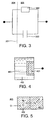
- Figure 4 shows an electrode of a first embodiment of the invention and comprising a metal element 401 (e.g. a wire, a plate, or a film completely covering an underlying conductor) coated with an ionic compound 402 of the same metal, which is sparingly soluble in the fluid of the flow to be measured 403.
- a metal element 401 e.g. a wire, a plate, or a film completely covering an underlying conductor
- an ionic compound 402 of the same metal which is sparingly soluble in the fluid of the flow to be measured 403.
- the metal 401 is silver, with the accompanying compound 402 being silver chloride.
- Figure 5 illustrates the fully-reversible, galvanic exchange of charge between the fluid 403 and the metal 401 by means of silver ions crossing the phase boundary between the solid silver electrode 401 and the hydrated silver chloride layer 402.
- the electrical potential across the interface is defined by the Nernst equation, which in turn depends on the surface concentration of AgC1 and the liquid concentration of C1 ions. While these quantities will not be constant, they may normally be expected to vary on a timescale much greater than the period of the alternating magnetic field. In accordance with the invention, the timescale of this variation is significantly longer than for an electrode surface which does not possess a controlled ionic exchange mechanism.
- FIG 11 shows (curve C) the variation in noise N with frequency f for electrodes comprising silver chloride compared with conventional steel or carbon electrodes (curves A and B). Baseline is shown at D.
- Ionic compound layer 402 may be formed by the spontaneous reaction of the metal surface with species ordinarily present in the fluid. For example, silver electrodes are likely to react with the treatment agents (or residues) in a chlorinated water supply, ultimately producing silver chloride.
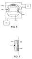
- FIG. 6 illustrates apparatus for implementing a method for boosting the quantity of ionic compound for situations where spontaneous reactions are insufficient.
- a third electrode 604 is provided for making contact to the fluid 603, in addition to the measuring electrodes 601 and 602. Electrode 604 need not be made of the same material as 601 and 602 (e.g. graphite or steel would suffice).
- control electronics 605 At intervals determined by control electronics 605, a substantial potential is applied between electrode 604, and the measuring electrodes 601 and 602.
- the measuring electrodes 601 and 602 would both be held at a positive potential with respect to electrode 604, sufficient to cause a quantity of the silver in electrodes 601 and 602 to react with negatively charged ionic species in the vicinity.
- the ionic species would preferably be chloride, and the potential applied between the electrodes may be chosen to favour such a reaction.
- the interval and duration of the above treatment may be determined in a number of ways. In the simplest implementation, the intervals at which it was applied would be fixed prior to installation. Alternatively, the intervals may be calculated according to properties of the electrical signal detected by the measuring unit 606. For example, an increased random variation in the signal from the electrodes (i.e. more noise) would signal that the electrode impedance is rising, most probably due to the depletion of ionic compound. This could be used to trigger a cycle of treatment to restore the coating. Alternatively, the state of the electrode coating could be determined using an active impedance measurement applied by the unit 406.
- Figure 7 shows an electrode prepared using the above method and comprising a flat section of silver 701 coated electrochemically with a thin film of silver chloride 702. Positioned in direct contact with the flowing liquid 703, and preferably flush with the wall of the flow tube so as to reduce turbulence and the corresponding measurement noise and uncertainty, its surface will tend to be abraded over time by particulates in the liquid, thereby helping to maintain an active electrode surface.
- Electrode 802 is monolithic, i.e. a single solid piece of wire or plate.
- a sintered construction is also possible.
- Metallic silver in the form of granules may also be included in the sintered silver chloride layer 801, the proportion of silver granules being chosen such that a substantial number make electrical contact with one another.
- Such a mixture of silver and silver chloride granules may be formed on a third monolithic metallic element such as a silver rod or plate.
- Figure 9 shows a further, more robust electrode construction according to the present invention that is also more stable with time and less susceptible to depletion and interference from contamination or flow effects.
- a monolithic silver plate 901 is set back behind a protective porous element, such as a frit 902, with an intervening reservoir 903 of silver chloride, which may be granules of silver chloride and/or silver, a powder or a sinter.
- Figure 10 represents a composite of figures 7 and 8, with sintered granules of silver chloride 1001 set in a central recess 1002 within a solid silver element 1003.
- the sintered section provides the most stable electrode under benign conditions, while the exposed silver (shown with a silver chloride layer at 1004) is better for coping with challenging conditions, e.g. dirty water, where porous elements are more likely to become blocked.
- the silver chloride layer formed over the metal is too thick, it adds an excessive series impedance to the total electric circuit. If it is too thin, the concentration is insufficient to maintain the required electrochemical reactions.
- the optimal amount of chloride may be determined by monitoring the electrical impedance of the electrode in a stable electrolyte, either during electrode fabrication, or during subsequent operation. Cathodic or anodic treatment should be applied until the impedance is at its lowest achievable point.
- the measured component of the impedance may be capacitance, resistance or a combination of the two. It may be measured between the terminal of the electrode and the terminal of a second electrode immersed in the same electrolyte and which may be another flow meter electrode. Alternatively, two electrodes may be maintained at the same mean electrical potential during treatment in such a way that a small differential alternating potential may be applied in order to measure the small-signal impedance between them (e.g. by connecting the electrode terminals together with an inductor).
- each electrode acts as a separate electrochemical half-cell, with a corresponding potential difference relative to the liquid. If the electrodes are not identical, the difference between the two half-cell potentials will be present between the electrode terminals, and this may cause problems with the subsequent amplification circuitry (e.g. saturation).
- the electrodes may be treated until they reach a common electrochemical half-cell potential. This may involve one or more of anodization, cathodization, exposure to a chemical agent or light, as described elsewhere in this document, the half-cell potential of the electrode being measured against a fixed standard half-cell, or against a second electrode which is not being treated at the same time.
- the treatment may involve connecting the terminals of two or more similar electrodes together for a period of time, while the electrodes are immersed in a common conductive electrolyte.
- Such electrode conditioning may be applied during the operating lifetime of the finished instrument, by the host electronics, as well as during initial fabrication.
- the noise and electrical characteristics of the electrode can be improved by increasing its active surface area and thereby reducing its interface impedance. This can be achieved by known mechanical and electrochemical roughening techniques. Furthermore, by reversing the flow of current in the anodization treatment described above, AgCl can be converted back to metallic Ag, the re-growth of metal being as dendrites of metallic Ag form in amongst the AgCl, growing out from the metal surface. This also has the effect of increasing the active surface area of the silver electrode and is applicable to both the monolithic and sintered constructions, where it can be used to grow dendrites of metallic silver in amongst the granules.
- the step of increasing surface area may be alternated with the step of formation of silver chloride as described above. It may also be carried out using other known means of reduction, for example heating in hydrogen gas or exposure to light.
- the invention has been described by way of examples only and that a wide variety of modifications can be made without departing from the scope of the invention.
- the invention is not restricted to silver or its ionic compound or salt, silver chloride. Gold and platinum may also yield good results.
- the invention is also applicable to fluids other than water.
Landscapes
- Physics & Mathematics (AREA)
- Electromagnetism (AREA)
- Fluid Mechanics (AREA)
- General Physics & Mathematics (AREA)
- Engineering & Computer Science (AREA)
- Power Engineering (AREA)
- Measuring Volume Flow (AREA)
- Paper (AREA)
- Water Treatment By Electricity Or Magnetism (AREA)
- Details Of Flowmeters (AREA)
- Magnetically Actuated Valves (AREA)
Abstract
Description
- This invention relates to magnetic flow transducers and in particular to magnetic water flow meters.
- In a conventional utility water meter, a mechanical flow transducer (typically positive displacement or single/multi-jet turbine) is coupled to a register mechanism that measures the number of repetitive cycles of the transducer. This mechanism is often a mechanical odometer. To interface this to the electronics required for remote meter reading can be cumbersome and expensive, even when the odometer is replaced by a solid state register having digital counters.
- Use of a flow transducer that is also solid-state reduces such interface problems. Such a flow transducer is a magnetic flow transducer of a kind that is well known: GB1303730A discloses a transducer in which the electrodes comprise elongated copper-containing conductor wire surrounded by a pervious insulation materal. SU800650B discloses a flow meter in which an electrode is enveloped by the use of a protective system in the form of a galvanic pair consisting of a grid electrode made of catalytic material for reinstatement of oxygen and directly coupled to an anode which surrounds the measuring electrode and made of stationary potential material with respect to reinstatement of oxygen. US3299703 claims a flow meter in which electrodes are placed in recesses formed in the internal wall of a flow conduit and where a wetting agent is placed in the recesses between the electrodes and the liquid. JP54116960A discloses a flow meter in which a pair of electrodes are supplied with a positive potential so as to keep the electrode surfaces clean.
Such a flow transducer is also shown by way of example in the cross-sectional view of figure 1. Flow tube, 101 incorporates amagnetic transducer 109 comprising a pair of electrodes, 102, disposed across a diameter of thepipe 101, with at least part of one surface of eachelectrode 102 in intimate contact with thefluid 108 in the pipe. Magnetic pole pieces, 103, are disposed across the orthogonal diameter of thepipe 101 and linked by a magnetic circuit, 104. As is well known in the art, themagnetic field 107 imparts a force on charged species moving with a bulk medium (ions in the case of water), causing the charged species to migrate in a direction orthogonal to both the magnetic field and the direction of bulk fluid motion. The mutual displacement of oppositely charged species results in an electric field along the direction of migration, which builds up until the electrostatic force on a given ion is balanced by the magnetic force. Since the magnetic force depends implicitly on the bulk medium flow velocity, measurement of the opposing electric field (or potential difference) provides a convenient means for determining the flow rate, whilst integration over time allows the total volume that has passed through the tube to be calculated. Circuitry for processing the electrode signals to obtain such measurements is well known in the art and consequently not described in greater detail here. - As is also well known, it can be advantageous to alternate the applied magnetic field, so as to overcome various limitations of a static field measurement. One such limitation is imposed by the nature of the electrodes used to measure the electrical potential difference in the fluid. An ideal electrode will form a perfect electrical connection to the fluid, with no energy barrier to the exchange of charge either way across the solid-liquid interface. This is seldom observed in practical systems, and it is much more likely that an electrical potential difference will be present across the interface. The potential difference is often poorly defined, and varies randomly with time such that it exhibits a noise spectrum that is inversely proportional to frequency ('1/f). A static field (DC) measurement will therefore be subject to large instantaneous errors.
- Alternating the applied magnetic field at a known frequency fo partially overcomes this problem: as shown in figure 2, this results in the desired
electrical signal 201 also being present at the frequency fo which is chosen to be significantly higher than the characteristic frequency of theelectrode noise spectrum 202. Measurement of the electrical signal amplitude a provides an indication of the flow rate that is substantially free of errors. - A further reason for applying an alternating magnetic field is that the small-signal electrical impedance of typical electrodes, as perceived by a measuring circuit attached between them, also falls with increasing frequency. The measuring circuit may therefore be permitted to draw more current from the signal source, without causing substantial errors. The principal advantage is that a simpler, cheaper measuring circuit design may be adopted.
- To understand the frequency-dependent behaviour of the electrodes, it is useful to consider a simple electrical model of figure 3 that is often applied to the solid-
liquid interface 301, consisting of aresistor 302 in parallel with acapacitor 303. The direct exchange of charged species between thesolid 304 and theliquid 305 is signified by the flow of current through theresistor 302, while thecapacitor 303 represents the tendency or charged species to accumulate in the vicinity of the interface, without actually crossing it. At frequencies substantially above 1Hz, thecapacitor 303 generally provides the easier route for the flow of a small-signal current through a solid-liquid interface. - In the device of figure 1, an alternating magnetic field is achieved by means of
coils 105 wound around part ofmagnetic circuit 104 and supplied with a suitable alternating current waveform. Furthermore, to reduce power consumption, it is known to providemagnetic circuit 104 with one ormore elements 106 exhibiting magnetic remenance so that the coils need only be energised when it is required to change the state of the magnetic field. - The present invention has as an objective yet further reduction in the power consumption of magnetic flow transducers.
- Accordingly, the invention consists in a magnetic flow transducer according to
claim 1 or claim 2. An electrode as defined in one of these claims has lower noise energy at frequencies below 5Hz than an electrode comprising carbon or corrosion-resistant metal alloy. - The invention is based on the recognition that by using an electrode having lower noise energy at low frequencies than the electrodes conventionally used in water meters, the frequency of the alternating magnetic field can be reduced for the same signal to noise ratio which in turn reduces the power consumption of the transducer.
- In contrast, the electrodes of known magnetic flow transducers are chosen for their immunity to corrosion effects and consequently made of corrosion-resistant metal alloys such as stainless steel or Hastelloy. In such known transducers, the electrochemical potential across the interface is poorly-defined, permitting large variations over a longer period of time, of the order of seconds. However, since known transducers operate at a magnetic field frequency much greater than 1 Hz, this has not caused problems. Thus, expressed differently, an electrode in accord with the present invention has a noise characteristic at magnetic field frequencies around 1 Hz that is lower than that of an electrode comprising corrosion-resistant metal alloy.
- The electrode according to the invention is configured such that a galvanic current flows across its interface with the fluid of the flow. A galvanic current arises due to the movement or exchange of charged species through the solid-liquid interface. It is distinct from the displacement current which flows between the liquid and sensor electrodes in known magnetic flow meters and which flows as the result of opposing sheets of charge building up or dispersing either side of an interface without actually crossing the phase boundary. The galvanic current configuration significantly improves the electrical impedance and noise characteristics of the electrode.
- Furthermore, the electrode according to the invention is configured such that the galvanic current is carried by ions. Silver ions are particularly advantageous since solid silver is stable in water over a long period of time and does not corrode significantly. Moreover, it is non-toxic and a permitted food additive (E174). Silver is also close to copper in the electrochemical series, reducing the risk of unwanted electrolytic corrosion in water pipes. It is also biocidal, helping to prevent stagnation and formation of troublesome biofilms in and around electrodes.
- In addition, the arrangement of a metal and a salt of that metal interposed between the metal and the fluid of the flow assists the charge exchange between the conductor and the fluid that underlie galvanic current. The salt or ionic compound is preferably sparingly soluble in the fluid of the flow of which is to be measured and is thus retained at the electrode. Where the metal is silver, the ionic compound may be a silver halide salt. Furthermore, where the fluid is water, such silver halide salts are advantageously formed by the ions most commonly present in tap water (chloride, fluoride). Silver halides form a stable electrochemical half-cells in contact with the metal.
- In accordance with the invention, the layer of metal salt is electrochemically deposited on a metal surface, e.g by anodizing or comprises a sintered layer of metal salt on a metal surface. The thickness of the layer will affect the impedance of the electrode: if it is too thick, it will add an excessive series impedance to the total electric Circuit, whereas if it is too thin, the concentration will be insufficient to maintain the required electrochemical reactions. The thickness of the layer is therefore preferably chosen, e.g. empirically, to lie between these two extremes such that the impedance of the electrode is at a minimum.
Further improvement in the noise and electrical characteristics may be achieved by an electrode having a metal surface that has been roughened so as to increase its active area. This may conveniently be achieved by reducing some of the metal salt back to metal, which typically results in a re-growth of metal that is nonuniform and rough. - Preferably, a pair of electrodes of the Magnetic flow transducer will be balanced so as to minimise the offset potential between the two. Each electrode acts as a separate electrochemical half-cell, with a corresponding potential difference relative to the liquid. If the electrodes are not identical, the difference between the two half-cell potentials will be present between the electrode terminals, and this may cause problems with the subsequent amplification circuitry (e.g. saturation).
- The low-power advantages of the above invention are further enhanced by the reduction in power consumption obtained when the magnetic field is generated by means exhibiting magnetic remanance as discussed above. The invention also comprises a flow meter incorporating such a magnetic transducer, where the low power consumption of the transducer also makes feasible the use of battery power (shown at 110 in figure 1) and the advantages in terms of ease of installation that this brings.
- The invention is diagrammatically illustrated, by way of example, in the accompanying drawings, in which:
- Figure 1 is a cross-sectional view of a flow tube equipped with a magnetic flow transducer;
- Figure 2 illustrates the amplitude/frequency characteristics of the signal from the electrodes;
- Figure 3 is a simple electrical model of the solid-liquid interface;
- Figure 4 shows an electrode of a first embodiment of the invention;
- Figure 5 illustrates the fully-reversible, galvanic exchange of charge between the fluid and the metal;
- Figure 6 illustrates an arrangement whereby the electrodes of the invention may be formed;
- Figure 7 shows an electrode prepared using the arrangement of figure 6;
- Figure 8 shows a second electrode construction according to the invention;
- Figure 9 shows a third electrode construction according to the invention;
- Figure 10 shows a fourth electrode construction according to the invention;
- Figure 11 is a graph of noise density against frequency for various electrode materials.
- Figure 4 shows an electrode of a first embodiment of the invention and comprising a metal element 401 (e.g. a wire, a plate, or a film completely covering an underlying conductor) coated with an
ionic compound 402 of the same metal, which is sparingly soluble in the fluid of the flow to be measured 403. - In the example shown, the
metal 401 is silver, with the accompanyingcompound 402 being silver chloride. Figure 5 illustrates the fully-reversible, galvanic exchange of charge between the fluid 403 and themetal 401 by means of silver ions crossing the phase boundary between thesolid silver electrode 401 and the hydratedsilver chloride layer 402. The electrical potential across the interface is defined by the Nernst equation, which in turn depends on the surface concentration of AgC1 and the liquid concentration of C1 ions. While these quantities will not be constant, they may normally be expected to vary on a timescale much greater than the period of the alternating magnetic field. In accordance with the invention, the timescale of this variation is significantly longer than for an electrode surface which does not possess a controlled ionic exchange mechanism. Accordingly, operation at a lower frequency is facilitated because the noise energy is reduced. Figure 11 shows (curve C) the variation in noise N with frequency f for electrodes comprising silver chloride compared with conventional steel or carbon electrodes (curves A and B). Baseline is shown at D. -
Ionic compound layer 402 may be formed by the spontaneous reaction of the metal surface with species ordinarily present in the fluid. For example, silver electrodes are likely to react with the treatment agents (or residues) in a chlorinated water supply, ultimately producing silver chloride. - Figure 6 illustrates apparatus for implementing a method for boosting the quantity of ionic compound for situations where spontaneous reactions are insufficient. A
third electrode 604 is provided for making contact to the fluid 603, in addition to the measuringelectrodes Electrode 604 need not be made of the same material as 601 and 602 (e.g. graphite or steel would suffice). At intervals determined bycontrol electronics 605, a substantial potential is applied betweenelectrode 604, and the measuringelectrodes electrodes electrode 604, sufficient to cause a quantity of the silver inelectrodes - The interval and duration of the above treatment may be determined in a number of ways. In the simplest implementation, the intervals at which it was applied would be fixed prior to installation. Alternatively, the intervals may be calculated according to properties of the electrical signal detected by the measuring
unit 606. For example, an increased random variation in the signal from the electrodes (i.e. more noise) would signal that the electrode impedance is rising, most probably due to the depletion of ionic compound. This could be used to trigger a cycle of treatment to restore the coating. Alternatively, the state of the electrode coating could be determined using an active impedance measurement applied by the unit 406. - Figure 7 shows an electrode prepared using the above method and comprising a flat section of
silver 701 coated electrochemically with a thin film of silver chloride 702. Positioned in direct contact with the flowingliquid 703, and preferably flush with the wall of the flow tube so as to reduce turbulence and the corresponding measurement noise and uncertainty, its surface will tend to be abraded over time by particulates in the liquid, thereby helping to maintain an active electrode surface. - Greater surface area, along with a more persistent reservoir of silver chloride, may be obtained by the use of silver chloride sintered onto a metal backing electrode, as shown at 801 and 802 respectively in figure 8. As shown,
electrode 802 is monolithic, i.e. a single solid piece of wire or plate. However, a sintered construction is also possible. Metallic silver in the form of granules may also be included in the sinteredsilver chloride layer 801, the proportion of silver granules being chosen such that a substantial number make electrical contact with one another. Such a mixture of silver and silver chloride granules may be formed on a third monolithic metallic element such as a silver rod or plate. - Figure 9 shows a further, more robust electrode construction according to the present invention that is also more stable with time and less susceptible to depletion and interference from contamination or flow effects. A
monolithic silver plate 901 is set back behind a protective porous element, such as afrit 902, with an interveningreservoir 903 of silver chloride, which may be granules of silver chloride and/or silver, a powder or a sinter. - Figure 10 represents a composite of figures 7 and 8, with sintered granules of
silver chloride 1001 set in acentral recess 1002 within asolid silver element 1003. The sintered section provides the most stable electrode under benign conditions, while the exposed silver (shown with a silver chloride layer at 1004) is better for coping with challenging conditions, e.g. dirty water, where porous elements are more likely to become blocked. - It will be appreciated that the silver chloride layer formed over the metal is too thick, it adds an excessive series impedance to the total electric circuit. If it is too thin, the concentration is insufficient to maintain the required electrochemical reactions. The optimal amount of chloride may be determined by monitoring the electrical impedance of the electrode in a stable electrolyte, either during electrode fabrication, or during subsequent operation. Cathodic or anodic treatment should be applied until the impedance is at its lowest achievable point.
- In practice, the measured component of the impedance may be capacitance, resistance or a combination of the two. It may be measured between the terminal of the electrode and the terminal of a second electrode immersed in the same electrolyte and which may be another flow meter electrode. Alternatively, two electrodes may be maintained at the same mean electrical potential during treatment in such a way that a small differential alternating potential may be applied in order to measure the small-signal impedance between them (e.g. by connecting the electrode terminals together with an inductor).
- It is also important to balance the electrodes to ensure the minimum electrical offset potential between the two. Each electrode acts as a separate electrochemical half-cell, with a corresponding potential difference relative to the liquid. If the electrodes are not identical, the difference between the two half-cell potentials will be present between the electrode terminals, and this may cause problems with the subsequent amplification circuitry (e.g. saturation).
- To this end, the electrodes may be treated until they reach a common electrochemical half-cell potential. This may involve one or more of anodization, cathodization, exposure to a chemical agent or light, as described elsewhere in this document, the half-cell potential of the electrode being measured against a fixed standard half-cell, or against a second electrode which is not being treated at the same time. Alternatively, the treatment may involve connecting the terminals of two or more similar electrodes together for a period of time, while the electrodes are immersed in a common conductive electrolyte. Such electrode conditioning may be applied during the operating lifetime of the finished instrument, by the host electronics, as well as during initial fabrication.
- The noise and electrical characteristics of the electrode can be improved by increasing its active surface area and thereby reducing its interface impedance. This can be achieved by known mechanical and electrochemical roughening techniques. Furthermore, by reversing the flow of current in the anodization treatment described above, AgCl can be converted back to metallic Ag, the re-growth of metal being as dendrites of metallic Ag form in amongst the AgCl, growing out from the metal surface. This also has the effect of increasing the active surface area of the silver electrode and is applicable to both the monolithic and sintered constructions, where it can be used to grow dendrites of metallic silver in amongst the granules.
- The step of increasing surface area may be alternated with the step of formation of silver chloride as described above. It may also be carried out using other known means of reduction, for example heating in hydrogen gas or exposure to light.
- It should be understood that the invention has been described by way of examples only and that a wide variety of modifications can be made without departing from the scope of the invention. In particular, the invention is not restricted to silver or its ionic compound or salt, silver chloride. Gold and platinum may also yield good results. Similarly, the invention is also applicable to fluids other than water.
Claims (15)
- Magnetic transducer (109) for measuring the flow of a fluid, the transducer having electrodes (102) and an alternating magnetic field (107), wherein an electrode comprises a metal (401) and a layer (402) of a salt of that metal arranged such that it is interposed between the metal and the fluid (403), the layer being electrochemically deposited or sintered.
- Magnetic transducer (109) for measuring the flow of a fluid, the transducer having electrodes (102) and an alternating magnetic field (107), wherein an electrode comprises a metal (401) and a layer (402) of a salt of that metal arranged such that it is interposed between the metal and the fluid, the layer being partially reduced back to metal.
- Magnetic transducer according to claim 1 or claim 2, wherein the layer (402) of salt is sparingly soluble in said fluid (403) the flow of which is to be measured.
- Magnetic transducer according to claim 3, wherein the metal (401) is silver.
- Magnetic transducer according to claim 4, wherein the layer (402) of salt comprises silver halide salt.
- Magnetic transducer according to claim 5, wherein said silver halide salt is silver chloride or silver fluoride.
- Magnetic transducer according to any one of claims 2 to 6, wherein said layer (402) is electrochemically deposited.
- Magnetic transducer according to any one of claims 2 to 6, wherein said layer (402) is sintered.
- Magnetic transducer according to any preceding claim, wherein the thickness of the layer (402) is such that the impedance of the electrode is at a minimum.
- Magnetic transducer according to any preceding claim when dependent on claim 1, wherein the surface of the electrode is roughened so as to increase its active area.
- Magnetic transducer according to claim 10, wherein the layer (402) is partially reduced back to metal.
- Magnetic transducer according to any preceding claim, wherein a pair of electrodes (102) of the magnetic transducer are balanced so as to minimise the offset potential between the two.
- Magnetic transducer according to any preceding claim and comprising means (103,104,105) for generating the alternating magnetic field (107), said means exhibiting magnetic remanance.
- Flow meter incorporating a magnetic transducer according to any preceding claim.
- Flow meter according to claim 14, wherein the meter is battery (110) powered.
Priority Applications (2)
| Application Number | Priority Date | Filing Date | Title |
|---|---|---|---|
| PL04727328T PL1616152T3 (en) | 2003-04-14 | 2004-04-14 | Magnetic flow transducer and flow meter incorporating the same |
| SI200430149T SI1616152T1 (en) | 2003-04-14 | 2004-04-14 | Magnetic flow transducer and flow meter incorporating the same |
Applications Claiming Priority (2)
| Application Number | Priority Date | Filing Date | Title |
|---|---|---|---|
| GBGB0308446.4A GB0308446D0 (en) | 2003-04-14 | 2003-04-14 | Low-power magnetic flow meter |
| PCT/GB2004/001618 WO2004090475A2 (en) | 2003-04-14 | 2004-04-14 | Magnetic flow transducer and flow meter incorporating the same |
Publications (2)
| Publication Number | Publication Date |
|---|---|
| EP1616152A2 EP1616152A2 (en) | 2006-01-18 |
| EP1616152B1 true EP1616152B1 (en) | 2006-11-02 |
Family
ID=9956652
Family Applications (1)
| Application Number | Title | Priority Date | Filing Date |
|---|---|---|---|
| EP04727328A Expired - Lifetime EP1616152B1 (en) | 2003-04-14 | 2004-04-14 | Magnetic flow transducer and flow meter incorporating the same |
Country Status (20)
| Country | Link |
|---|---|
| US (1) | US7472605B2 (en) |
| EP (1) | EP1616152B1 (en) |
| JP (1) | JP5094115B2 (en) |
| KR (1) | KR101045810B1 (en) |
| CN (1) | CN100365393C (en) |
| AT (1) | ATE344442T1 (en) |
| BR (1) | BRPI0409328B1 (en) |
| CA (1) | CA2521720C (en) |
| DE (1) | DE602004003042T2 (en) |
| EG (1) | EG23885A (en) |
| ES (1) | ES2276291T3 (en) |
| GB (1) | GB0308446D0 (en) |
| MX (1) | MXPA05011114A (en) |
| PL (1) | PL1616152T3 (en) |
| PT (1) | PT1616152E (en) |
| RU (1) | RU2352904C2 (en) |
| SI (1) | SI1616152T1 (en) |
| UA (1) | UA86197C2 (en) |
| WO (1) | WO2004090475A2 (en) |
| ZA (1) | ZA200508122B (en) |
Cited By (3)
| Publication number | Priority date | Publication date | Assignee | Title |
|---|---|---|---|---|
| DE202009017275U1 (en) | 2009-06-12 | 2010-06-02 | Sensus Metering Systems | Magnetic-inductive flowmeter |
| WO2010142450A1 (en) | 2009-06-12 | 2010-12-16 | Sensus Metering Systems | Magnetic-inductive flow meter |
| EP4538652A1 (en) * | 2023-10-12 | 2025-04-16 | Sensus Spectrum LLC. | Measurement apparatus |
Families Citing this family (15)
| Publication number | Priority date | Publication date | Assignee | Title |
|---|---|---|---|---|
| GB0414875D0 (en) * | 2004-07-02 | 2004-08-04 | Sentec Ltd | Improved electrode designs for a novel low-power magnetic flow meter |
| US7837660B2 (en) * | 2007-12-17 | 2010-11-23 | Ross Peter Jones | Recessed electrodes for sensing flow in ophthalmic surgical system |
| US8408070B2 (en) * | 2008-06-05 | 2013-04-02 | Siemens Aktiengesellschaft | Electromagnetic flowmeter and method incorporating the same |
| CN102292468B (en) * | 2009-02-04 | 2013-05-29 | 西门子公司 | Electromagnetic flowmeter having corrosion protection of measuring electrodes, and method incorporating the same |
| US9696188B2 (en) | 2013-03-14 | 2017-07-04 | Rosemount Inc. | Magnetic flowmeter with automatic adjustment based on sensed complex impedance |
| US20140363326A1 (en) | 2013-06-10 | 2014-12-11 | Grid Logic Incorporated | System and method for additive manufacturing |
| DE102015014617A1 (en) * | 2015-11-12 | 2017-05-18 | Diehl Metering Gmbh | Fluid counter with bioactive substance |
| DE102015014621A1 (en) * | 2015-11-12 | 2017-05-18 | Diehl Metering Gmbh | Fluid meter with bioactive coating |
| DE102015121730A1 (en) * | 2015-12-14 | 2017-06-14 | Endress+Hauser Flowtec Ag | Magnetic-inductive flowmeter |
| EP3411179B1 (en) | 2016-02-03 | 2024-08-14 | Grid Logic Incorporated | System and method for manufacturing a part |
| DE102016002015A1 (en) * | 2016-02-20 | 2017-08-24 | Diehl Metering Gmbh | Component for a fluid meter, method for its production and fluid meter |
| US10502599B2 (en) * | 2016-03-31 | 2019-12-10 | Rosemount Inc. | Polymeric magnetic flowmeter flow body assembly |
| GB201911971D0 (en) | 2019-08-21 | 2019-10-02 | Sentec Ltd | Improved electrode |
| US11813672B2 (en) | 2020-05-08 | 2023-11-14 | Grid Logic Incorporated | System and method for manufacturing a part |
| CN113049049B (en) * | 2021-03-10 | 2022-06-28 | 福水智联技术有限公司 | Water meter anti-rotation detection device and method |
Family Cites Families (26)
| Publication number | Priority date | Publication date | Assignee | Title |
|---|---|---|---|---|
| US3299703A (en) * | 1963-07-22 | 1967-01-24 | Ford Motor Co | Electromagnetic flowmeter |
| US4347738A (en) * | 1968-09-06 | 1982-09-07 | The United States Of America As Represented By The Secretary Of The Navy | Oceanographic transducer |
| GB1303730A (en) * | 1970-05-22 | 1973-01-17 | ||
| US3942377A (en) * | 1973-07-27 | 1976-03-09 | Arkady Savelievich Ginzburg | Electromagnetic flowmeter |
| JPS5140172A (en) * | 1974-10-02 | 1976-04-03 | Tokyo Shibaura Electric Co | RYUTAISOKUTEIYODENKYOKU |
| JPS54116960A (en) | 1978-03-03 | 1979-09-11 | Hitachi Ltd | Electromagnetic flow meter |
| SU800650A1 (en) * | 1979-03-11 | 1981-01-30 | Таллинский Политехнический Инсти-Тут | Electromagnetic flowmeter |
| JPS6212980Y2 (en) * | 1981-04-30 | 1987-04-03 | ||
| JPS6318259A (en) * | 1986-07-10 | 1988-01-26 | Terumo Corp | Reference electrode |
| JPS63105819U (en) * | 1986-12-26 | 1988-07-08 | ||
| DE3732981A1 (en) * | 1987-09-30 | 1989-04-13 | Basf Ag | METHOD FOR DYING PAPER |
| CN1016727B (en) * | 1987-12-25 | 1992-05-20 | 山武·霍尼韦尔公司 | Method for manufacturing electromagnetic flowmeter electrodes |
| US5296284A (en) * | 1988-04-05 | 1994-03-22 | J. M. Huber Corporation | Dyed hectorite pigments and applications |
| US5416181A (en) * | 1989-02-10 | 1995-05-16 | Penford Products Company | Reinforced films made from water soluble polymers |
| CN2072215U (en) * | 1990-06-06 | 1991-02-27 | 机械电子工业部上海工业自动化仪表研究所 | Ceramic electromagnetic flow meter |
| CA2048186A1 (en) * | 1990-08-10 | 1992-02-11 | Yoshifumi Yoshida | Paper coating composition |
| JP3043087B2 (en) * | 1991-03-25 | 2000-05-22 | 愛知時計電機株式会社 | Residual magnetic electromagnetic flowmeter |
| KR100278934B1 (en) * | 1992-01-10 | 2001-01-15 | 고마쓰바라 히로유끼 | Copolymer latex production method and its use |
| JP3130729B2 (en) * | 1994-03-16 | 2001-01-31 | 株式会社東芝 | Electromagnetic flow meter |
| JP3238084B2 (en) | 1996-12-04 | 2001-12-10 | 株式会社東芝 | Electromagnetic flow measurement system |
| US5800870A (en) * | 1997-03-03 | 1998-09-01 | Penford Products Co. | Size press coating method |
| US6387500B1 (en) * | 1997-11-06 | 2002-05-14 | Cabot Corporation | Multi-layered coatings and coated paper and paperboards |
| JP3820052B2 (en) * | 1999-02-22 | 2006-09-13 | 三菱重工食品包装機械株式会社 | Electromagnetic flow meter |
| DE19911746A1 (en) * | 1999-03-16 | 2000-09-21 | Basf Ag | Diamond electrodes |
| US20020066543A1 (en) * | 2000-12-05 | 2002-06-06 | Spectra Systems Corporation | Fluorescent micro-particles embedded in a pigmented fluorescent coating for optical document security |
| GB0414875D0 (en) * | 2004-07-02 | 2004-08-04 | Sentec Ltd | Improved electrode designs for a novel low-power magnetic flow meter |
-
2003
- 2003-04-14 GB GBGB0308446.4A patent/GB0308446D0/en not_active Ceased
-
2004
- 2004-04-14 EP EP04727328A patent/EP1616152B1/en not_active Expired - Lifetime
- 2004-04-14 CN CNB2004800098818A patent/CN100365393C/en not_active Expired - Lifetime
- 2004-04-14 PT PT04727328T patent/PT1616152E/en unknown
- 2004-04-14 PL PL04727328T patent/PL1616152T3/en unknown
- 2004-04-14 AT AT04727328T patent/ATE344442T1/en not_active IP Right Cessation
- 2004-04-14 KR KR1020057019456A patent/KR101045810B1/en not_active Expired - Lifetime
- 2004-04-14 UA UAA200509446A patent/UA86197C2/en unknown
- 2004-04-14 JP JP2006506125A patent/JP5094115B2/en not_active Expired - Lifetime
- 2004-04-14 RU RU2005135120/28A patent/RU2352904C2/en active
- 2004-04-14 WO PCT/GB2004/001618 patent/WO2004090475A2/en not_active Ceased
- 2004-04-14 SI SI200430149T patent/SI1616152T1/en unknown
- 2004-04-14 CA CA2521720A patent/CA2521720C/en not_active Expired - Lifetime
- 2004-04-14 MX MXPA05011114A patent/MXPA05011114A/en active IP Right Grant
- 2004-04-14 DE DE602004003042T patent/DE602004003042T2/en not_active Expired - Lifetime
- 2004-04-14 ES ES04727328T patent/ES2276291T3/en not_active Expired - Lifetime
- 2004-04-14 US US10/552,530 patent/US7472605B2/en not_active Expired - Lifetime
- 2004-04-14 ZA ZA200508122A patent/ZA200508122B/en unknown
- 2004-04-14 BR BRPI0409328-3A patent/BRPI0409328B1/en not_active IP Right Cessation
-
2005
- 2005-10-13 EG EGNA2005000643 patent/EG23885A/en active
Cited By (4)
| Publication number | Priority date | Publication date | Assignee | Title |
|---|---|---|---|---|
| DE202009017275U1 (en) | 2009-06-12 | 2010-06-02 | Sensus Metering Systems | Magnetic-inductive flowmeter |
| WO2010142450A1 (en) | 2009-06-12 | 2010-12-16 | Sensus Metering Systems | Magnetic-inductive flow meter |
| US8448524B2 (en) | 2009-06-12 | 2013-05-28 | Sensus Usa Inc. | Magnetic inductive flow meter |
| EP4538652A1 (en) * | 2023-10-12 | 2025-04-16 | Sensus Spectrum LLC. | Measurement apparatus |
Also Published As
| Publication number | Publication date |
|---|---|
| PT1616152E (en) | 2007-02-28 |
| ES2276291T3 (en) | 2007-06-16 |
| CN1826511A (en) | 2006-08-30 |
| WO2004090475A2 (en) | 2004-10-21 |
| RU2352904C2 (en) | 2009-04-20 |
| CA2521720A1 (en) | 2004-10-21 |
| CA2521720C (en) | 2012-12-18 |
| DE602004003042T2 (en) | 2007-06-06 |
| GB0308446D0 (en) | 2003-05-21 |
| BRPI0409328A (en) | 2006-04-25 |
| DE602004003042D1 (en) | 2006-12-14 |
| RU2005135120A (en) | 2006-06-27 |
| EG23885A (en) | 2007-12-11 |
| JP2006522932A (en) | 2006-10-05 |
| BRPI0409328B1 (en) | 2017-10-24 |
| KR101045810B1 (en) | 2011-07-05 |
| CN100365393C (en) | 2008-01-30 |
| ZA200508122B (en) | 2007-03-28 |
| KR20060002992A (en) | 2006-01-09 |
| PL1616152T3 (en) | 2007-04-30 |
| WO2004090475A3 (en) | 2005-03-24 |
| MXPA05011114A (en) | 2006-04-18 |
| US20070022823A1 (en) | 2007-02-01 |
| UA86197C2 (en) | 2009-04-10 |
| JP5094115B2 (en) | 2012-12-12 |
| AU2004227185A1 (en) | 2004-10-21 |
| EP1616152A2 (en) | 2006-01-18 |
| SI1616152T1 (en) | 2007-06-30 |
| ATE344442T1 (en) | 2006-11-15 |
| US7472605B2 (en) | 2009-01-06 |
Similar Documents
| Publication | Publication Date | Title |
|---|---|---|
| US7472605B2 (en) | Magnetic transducer having electrodes with metal and a layer of a salt of that metal | |
| JP4141841B2 (en) | Sensor array and method for electrochemical corrosion monitoring | |
| CN100585344C (en) | Electrode for magnetic fluid sensor | |
| JP4921705B2 (en) | Method for operation of a magnetic induction flow measuring instrument | |
| US8587326B2 (en) | Method for energy-saving operation of a magneto-inductive flow measuring device | |
| RU2413182C2 (en) | Magnetic inductive flow metre | |
| JPS63502300A (en) | Plating sensors for monitoring corrosion or electroplating | |
| JP4991683B2 (en) | Electrochemical potential automatic correction device | |
| AU2004227185B2 (en) | Magnetic flow transducer and flow meter incorporating the same | |
| JP2783725B2 (en) | Moisture measurement method | |
| JPH11270860A (en) | Floor heating system with antifreeze deterioration detection function | |
| JP2000171432A (en) | Oxidizing / reducing substance concentration measuring apparatus and measuring method | |
| JPH0330851Y2 (en) | ||
| JPH0821757A (en) | Electromagnetic flow meter | |
| JP2001033424A (en) | Sensor for measuring the concentration of oxidizing / reducing substances | |
| TWI390187B (en) | Fluid flow detector, electrode and method of manufacturing same | |
| JPH0462336B2 (en) | ||
| JPH0368339B2 (en) |
Legal Events
| Date | Code | Title | Description |
|---|---|---|---|
| PUAI | Public reference made under article 153(3) epc to a published international application that has entered the european phase |
Free format text: ORIGINAL CODE: 0009012 |
|
| 17P | Request for examination filed |
Effective date: 20051108 |
|
| AK | Designated contracting states |
Kind code of ref document: A2 Designated state(s): AT BE BG CH CY CZ DE DK EE ES FI FR GB GR HU IE IT LI LU MC NL PL PT RO SE SI SK TR |
|
| AX | Request for extension of the european patent |
Extension state: AL HR LT LV MK |
|
| DAX | Request for extension of the european patent (deleted) | ||
| GRAP | Despatch of communication of intention to grant a patent |
Free format text: ORIGINAL CODE: EPIDOSNIGR1 |
|
| GRAS | Grant fee paid |
Free format text: ORIGINAL CODE: EPIDOSNIGR3 |
|
| GRAA | (expected) grant |
Free format text: ORIGINAL CODE: 0009210 |
|
| AK | Designated contracting states |
Kind code of ref document: B1 Designated state(s): AT BE BG CH CY CZ DE DK EE ES FI FR GB GR HU IE IT LI LU MC NL PL PT RO SE SI SK TR |
|
| PG25 | Lapsed in a contracting state [announced via postgrant information from national office to epo] |
Ref country code: LI Free format text: LAPSE BECAUSE OF FAILURE TO SUBMIT A TRANSLATION OF THE DESCRIPTION OR TO PAY THE FEE WITHIN THE PRESCRIBED TIME-LIMIT Effective date: 20061102 Ref country code: NL Free format text: LAPSE BECAUSE OF FAILURE TO SUBMIT A TRANSLATION OF THE DESCRIPTION OR TO PAY THE FEE WITHIN THE PRESCRIBED TIME-LIMIT Effective date: 20061102 Ref country code: CH Free format text: LAPSE BECAUSE OF FAILURE TO SUBMIT A TRANSLATION OF THE DESCRIPTION OR TO PAY THE FEE WITHIN THE PRESCRIBED TIME-LIMIT Effective date: 20061102 Ref country code: AT Free format text: LAPSE BECAUSE OF FAILURE TO SUBMIT A TRANSLATION OF THE DESCRIPTION OR TO PAY THE FEE WITHIN THE PRESCRIBED TIME-LIMIT Effective date: 20061102 Ref country code: RO Free format text: LAPSE BECAUSE OF FAILURE TO SUBMIT A TRANSLATION OF THE DESCRIPTION OR TO PAY THE FEE WITHIN THE PRESCRIBED TIME-LIMIT Effective date: 20061102 Ref country code: FI Free format text: LAPSE BECAUSE OF FAILURE TO SUBMIT A TRANSLATION OF THE DESCRIPTION OR TO PAY THE FEE WITHIN THE PRESCRIBED TIME-LIMIT Effective date: 20061102 Ref country code: CZ Free format text: LAPSE BECAUSE OF FAILURE TO SUBMIT A TRANSLATION OF THE DESCRIPTION OR TO PAY THE FEE WITHIN THE PRESCRIBED TIME-LIMIT Effective date: 20061102 |
|
| REG | Reference to a national code |
Ref country code: GB Ref legal event code: FG4D |
|
| REG | Reference to a national code |
Ref country code: IE Ref legal event code: FG4D |
|
| REG | Reference to a national code |
Ref country code: CH Ref legal event code: EP |
|
| REF | Corresponds to: |
Ref document number: 602004003042 Country of ref document: DE Date of ref document: 20061214 Kind code of ref document: P |
|
| PG25 | Lapsed in a contracting state [announced via postgrant information from national office to epo] |
Ref country code: BG Free format text: LAPSE BECAUSE OF FAILURE TO SUBMIT A TRANSLATION OF THE DESCRIPTION OR TO PAY THE FEE WITHIN THE PRESCRIBED TIME-LIMIT Effective date: 20070202 Ref country code: DK Free format text: LAPSE BECAUSE OF FAILURE TO SUBMIT A TRANSLATION OF THE DESCRIPTION OR TO PAY THE FEE WITHIN THE PRESCRIBED TIME-LIMIT Effective date: 20070202 |
|
| REG | Reference to a national code |
Ref country code: SE Ref legal event code: TRGR |
|
| REG | Reference to a national code |
Ref country code: PT Ref legal event code: SC4A Free format text: AVAILABILITY OF NATIONAL TRANSLATION Effective date: 20070129 |
|
| REG | Reference to a national code |
Ref country code: PL Ref legal event code: T3 |
|
| NLV1 | Nl: lapsed or annulled due to failure to fulfill the requirements of art. 29p and 29m of the patents act | ||
| REG | Reference to a national code |
Ref country code: CH Ref legal event code: PL |
|
| ET | Fr: translation filed | ||
| REG | Reference to a national code |
Ref country code: ES Ref legal event code: FG2A Ref document number: 2276291 Country of ref document: ES Kind code of ref document: T3 |
|
| PLBE | No opposition filed within time limit |
Free format text: ORIGINAL CODE: 0009261 |
|
| STAA | Information on the status of an ep patent application or granted ep patent |
Free format text: STATUS: NO OPPOSITION FILED WITHIN TIME LIMIT |
|
| 26N | No opposition filed |
Effective date: 20070803 |
|
| PG25 | Lapsed in a contracting state [announced via postgrant information from national office to epo] |
Ref country code: GR Free format text: LAPSE BECAUSE OF FAILURE TO SUBMIT A TRANSLATION OF THE DESCRIPTION OR TO PAY THE FEE WITHIN THE PRESCRIBED TIME-LIMIT Effective date: 20070203 |
|
| PG25 | Lapsed in a contracting state [announced via postgrant information from national office to epo] |
Ref country code: IE Free format text: LAPSE BECAUSE OF NON-PAYMENT OF DUE FEES Effective date: 20070416 |
|
| PG25 | Lapsed in a contracting state [announced via postgrant information from national office to epo] |
Ref country code: EE Free format text: LAPSE BECAUSE OF FAILURE TO SUBMIT A TRANSLATION OF THE DESCRIPTION OR TO PAY THE FEE WITHIN THE PRESCRIBED TIME-LIMIT Effective date: 20061102 |
|
| PG25 | Lapsed in a contracting state [announced via postgrant information from national office to epo] |
Ref country code: MC Free format text: LAPSE BECAUSE OF NON-PAYMENT OF DUE FEES Effective date: 20070430 |
|
| PG25 | Lapsed in a contracting state [announced via postgrant information from national office to epo] |
Ref country code: CY Free format text: LAPSE BECAUSE OF FAILURE TO SUBMIT A TRANSLATION OF THE DESCRIPTION OR TO PAY THE FEE WITHIN THE PRESCRIBED TIME-LIMIT Effective date: 20061102 Ref country code: LU Free format text: LAPSE BECAUSE OF NON-PAYMENT OF DUE FEES Effective date: 20070414 |
|
| PG25 | Lapsed in a contracting state [announced via postgrant information from national office to epo] |
Ref country code: HU Free format text: LAPSE BECAUSE OF FAILURE TO SUBMIT A TRANSLATION OF THE DESCRIPTION OR TO PAY THE FEE WITHIN THE PRESCRIBED TIME-LIMIT Effective date: 20070503 |
|
| REG | Reference to a national code |
Ref country code: FR Ref legal event code: PLFP Year of fee payment: 13 |
|
| REG | Reference to a national code |
Ref country code: FR Ref legal event code: PLFP Year of fee payment: 14 |
|
| REG | Reference to a national code |
Ref country code: FR Ref legal event code: PLFP Year of fee payment: 15 |
|
| PGFP | Annual fee paid to national office [announced via postgrant information from national office to epo] |
Ref country code: TR Payment date: 20230329 Year of fee payment: 20 Ref country code: SK Payment date: 20230321 Year of fee payment: 20 Ref country code: PT Payment date: 20230320 Year of fee payment: 20 Ref country code: PL Payment date: 20230321 Year of fee payment: 20 |
|
| PGFP | Annual fee paid to national office [announced via postgrant information from national office to epo] |
Ref country code: IT Payment date: 20230419 Year of fee payment: 20 Ref country code: FR Payment date: 20230425 Year of fee payment: 20 Ref country code: ES Payment date: 20230503 Year of fee payment: 20 Ref country code: DE Payment date: 20230427 Year of fee payment: 20 |
|
| PGFP | Annual fee paid to national office [announced via postgrant information from national office to epo] |
Ref country code: SI Payment date: 20230321 Year of fee payment: 20 Ref country code: SE Payment date: 20230427 Year of fee payment: 20 |
|
| PGFP | Annual fee paid to national office [announced via postgrant information from national office to epo] |
Ref country code: BE Payment date: 20230427 Year of fee payment: 20 |
|
| PGFP | Annual fee paid to national office [announced via postgrant information from national office to epo] |
Ref country code: GB Payment date: 20230427 Year of fee payment: 20 |
|
| REG | Reference to a national code |
Ref country code: DE Ref legal event code: R071 Ref document number: 602004003042 Country of ref document: DE |
|
| REG | Reference to a national code |
Ref country code: SK Ref legal event code: MK4A Ref document number: E 1462 Country of ref document: SK Expiry date: 20240414 |
|
| PG25 | Lapsed in a contracting state [announced via postgrant information from national office to epo] |
Ref country code: ES Free format text: LAPSE BECAUSE OF EXPIRATION OF PROTECTION Effective date: 20240415 |
|
| REG | Reference to a national code |
Ref country code: ES Ref legal event code: FD2A Effective date: 20240426 |
|
| PG25 | Lapsed in a contracting state [announced via postgrant information from national office to epo] |
Ref country code: ES Free format text: LAPSE BECAUSE OF EXPIRATION OF PROTECTION Effective date: 20240415 |
|
| PG25 | Lapsed in a contracting state [announced via postgrant information from national office to epo] |
Ref country code: SI Free format text: LAPSE BECAUSE OF EXPIRATION OF PROTECTION Effective date: 20240415 |
|
| REG | Reference to a national code |
Ref country code: BE Ref legal event code: MK Effective date: 20240414 |
|
| REG | Reference to a national code |
Ref country code: GB Ref legal event code: PE20 Expiry date: 20240413 |
|
| REG | Reference to a national code |
Ref country code: SE Ref legal event code: EUG |
|
| PG25 | Lapsed in a contracting state [announced via postgrant information from national office to epo] |
Ref country code: SI Free format text: LAPSE BECAUSE OF EXPIRATION OF PROTECTION Effective date: 20240415 |
|
| PG25 | Lapsed in a contracting state [announced via postgrant information from national office to epo] |
Ref country code: GB Free format text: LAPSE BECAUSE OF EXPIRATION OF PROTECTION Effective date: 20240413 |
|
| PG25 | Lapsed in a contracting state [announced via postgrant information from national office to epo] |
Ref country code: SK Free format text: LAPSE BECAUSE OF EXPIRATION OF PROTECTION Effective date: 20240414 |
|
| PG25 | Lapsed in a contracting state [announced via postgrant information from national office to epo] |
Ref country code: SK Free format text: LAPSE BECAUSE OF EXPIRATION OF PROTECTION Effective date: 20240414 Ref country code: GB Free format text: LAPSE BECAUSE OF EXPIRATION OF PROTECTION Effective date: 20240413 |
|
| PG25 | Lapsed in a contracting state [announced via postgrant information from national office to epo] |
Ref country code: PT Free format text: LAPSE BECAUSE OF EXPIRATION OF PROTECTION Effective date: 20240424 |
|
| PG25 | Lapsed in a contracting state [announced via postgrant information from national office to epo] |
Ref country code: PT Free format text: LAPSE BECAUSE OF EXPIRATION OF PROTECTION Effective date: 20240424 |