EP1615554B1 - Method and arrangement for influencing magnetic particles and detecting interfering material - Google Patents
Method and arrangement for influencing magnetic particles and detecting interfering material Download PDFInfo
- Publication number
- EP1615554B1 EP1615554B1 EP04725750.6A EP04725750A EP1615554B1 EP 1615554 B1 EP1615554 B1 EP 1615554B1 EP 04725750 A EP04725750 A EP 04725750A EP 1615554 B1 EP1615554 B1 EP 1615554B1
- Authority
- EP
- European Patent Office
- Prior art keywords
- interfering material
- magnetic particles
- arrangement
- signals
- sub
- Prior art date
- Legal status (The legal status is an assumption and is not a legal conclusion. Google has not performed a legal analysis and makes no representation as to the accuracy of the status listed.)
- Expired - Lifetime
Links
- 239000000463 material Substances 0.000 title claims description 58
- 230000002452 interceptive effect Effects 0.000 title claims description 55
- 239000006249 magnetic particle Substances 0.000 title claims description 36
- 238000000034 method Methods 0.000 title claims description 24
- 230000005291 magnetic effect Effects 0.000 claims description 57
- 230000009471 action Effects 0.000 claims description 29
- 230000008859 change Effects 0.000 claims description 20
- 230000005415 magnetization Effects 0.000 claims description 16
- 238000001514 detection method Methods 0.000 claims description 15
- 230000001939 inductive effect Effects 0.000 claims description 11
- 238000012545 processing Methods 0.000 claims description 8
- 239000002245 particle Substances 0.000 claims description 7
- 230000003595 spectral effect Effects 0.000 claims description 7
- 238000001228 spectrum Methods 0.000 claims description 7
- 229920006395 saturated elastomer Polymers 0.000 claims description 6
- 238000004458 analytical method Methods 0.000 claims description 5
- 238000005259 measurement Methods 0.000 claims description 4
- 230000002123 temporal effect Effects 0.000 claims 1
- 238000011835 investigation Methods 0.000 description 9
- 230000000694 effects Effects 0.000 description 6
- 239000003302 ferromagnetic material Substances 0.000 description 4
- 238000010438 heat treatment Methods 0.000 description 4
- 239000002184 metal Substances 0.000 description 4
- 229910000497 Amalgam Inorganic materials 0.000 description 3
- 230000004044 response Effects 0.000 description 3
- 210000001519 tissue Anatomy 0.000 description 3
- 230000001419 dependent effect Effects 0.000 description 2
- 238000010586 diagram Methods 0.000 description 2
- 230000009467 reduction Effects 0.000 description 2
- 239000000523 sample Substances 0.000 description 2
- 238000012216 screening Methods 0.000 description 2
- 238000004804 winding Methods 0.000 description 2
- 206010020843 Hyperthermia Diseases 0.000 description 1
- 230000002411 adverse Effects 0.000 description 1
- 229910045601 alloy Inorganic materials 0.000 description 1
- 239000000956 alloy Substances 0.000 description 1
- 230000009286 beneficial effect Effects 0.000 description 1
- 230000015572 biosynthetic process Effects 0.000 description 1
- 210000000988 bone and bone Anatomy 0.000 description 1
- 238000010276 construction Methods 0.000 description 1
- 238000003745 diagnosis Methods 0.000 description 1
- 230000005294 ferromagnetic effect Effects 0.000 description 1
- 230000036031 hyperthermia Effects 0.000 description 1
- 238000003384 imaging method Methods 0.000 description 1
- 230000002045 lasting effect Effects 0.000 description 1
- 239000000696 magnetic material Substances 0.000 description 1
- 239000003550 marker Substances 0.000 description 1
- 238000012544 monitoring process Methods 0.000 description 1
- 238000010606 normalization Methods 0.000 description 1
- 210000000056 organ Anatomy 0.000 description 1
- 238000007781 pre-processing Methods 0.000 description 1
- 230000035945 sensitivity Effects 0.000 description 1
- 230000003068 static effect Effects 0.000 description 1
- 239000000126 substance Substances 0.000 description 1
- 230000003245 working effect Effects 0.000 description 1
Images



Classifications
-
- A—HUMAN NECESSITIES
- A61—MEDICAL OR VETERINARY SCIENCE; HYGIENE
- A61N—ELECTROTHERAPY; MAGNETOTHERAPY; RADIATION THERAPY; ULTRASOUND THERAPY
- A61N2/00—Magnetotherapy
- A61N2/02—Magnetotherapy using magnetic fields produced by coils, including single turn loops or electromagnets
-
- A—HUMAN NECESSITIES
- A61—MEDICAL OR VETERINARY SCIENCE; HYGIENE
- A61N—ELECTROTHERAPY; MAGNETOTHERAPY; RADIATION THERAPY; ULTRASOUND THERAPY
- A61N1/00—Electrotherapy; Circuits therefor
- A61N1/40—Applying electric fields by inductive or capacitive coupling ; Applying radio-frequency signals
- A61N1/403—Applying electric fields by inductive or capacitive coupling ; Applying radio-frequency signals for thermotherapy, e.g. hyperthermia
- A61N1/406—Applying electric fields by inductive or capacitive coupling ; Applying radio-frequency signals for thermotherapy, e.g. hyperthermia using implantable thermoseeds or injected particles for localized hyperthermia
-
- A—HUMAN NECESSITIES
- A61—MEDICAL OR VETERINARY SCIENCE; HYGIENE
- A61B—DIAGNOSIS; SURGERY; IDENTIFICATION
- A61B5/00—Measuring for diagnostic purposes; Identification of persons
- A61B5/05—Detecting, measuring or recording for diagnosis by means of electric currents or magnetic fields; Measuring using microwaves or radio waves
- A61B5/0515—Magnetic particle imaging
Definitions
- the invention relates to a method and an arrangement for influencing magnetic particles in a region of action.
- Magnetic particles are relatively easy to detect and can therefore be used for examinations and investigations (particularly medical ones).
- An apparatus and method of this kind for determining the spatial distribution of magnetic particles in an examination zone i.e. a region of action
- suitable magnetic particles are described in German patent application DE 101 51 778 A1 .
- This patent application will be referred to below as D1.
- a spatially inhomogeneous magnetic field is generated that has at least one zone in which the magnetization of the particles is in a state of non-saturation. Changing the position of this zone within the examination zone produces a change in magnetization that can be detected from the outside and that gives information on the spatial distribution of the magnetic particles in the examination zone.
- EP 1 304 542 A2 is a document falling under Article 54(3) EPC and claiming the priority of D1.
- Magnetic particles can also be used to heat their surroundings, particularly in medical hyperthermia.
- a method and a system of this kind for the local heating of regions of an object by variation of the magnetization of magnetic or magnetizable substances is described in German patent application DE 102 38 853 A1 .
- This patent application will be referred to below as D2.
- the position in space of the two sub-zones in the target region is then changed for so long at a given frequency that the particles heat up to a desired temperature due to a frequent change in magnetization.
- US 2001/012915 A1 discloses a probe instrument using room-temperature sensor(s) that can measure magnetic susceptibilities variations.
- the instrument includes room temperature magnetic sensors, and detects the sample, that is the tissue response to an applied field coil.
- the sensors that can be used include magnetoresistive, fluxgate and magnetoinductive sensors.
- the applied field coil dimensions are chosen so that the applied field is optimized for maximum response from the item of interest while minimizing the effects due to the overlying tissue and at the same time not unduly increasing the sensitivity of the instrument to adjacent organs.
- the applied field is canceled at the position of the sensor.
- the detector assembly is oscillated while the examined patient remains stationary.
- DE 3813479 A1 discloses a device for accurately detecting and monitoring the position of an object inside biological tissue, particularly an endotracheal tube inside a patient's throat.
- US 6082366 A discloses a method and an arrangement for determining the position of a marker in an organic cavity, in particular for establishing local passage speeds within the framework of the medical diagnosis of the stomach-bowel tract.
- US 6541966 B1 discloses an apparatus for detecting a metal object.
- the object is a patient
- dental fillings of amalgam, artificial joints, rods or screws fitted in or on bones, or even items situated on the outside of the patient's body such as personal adornments (ear-rings, adornments in piercings) heat up.
- a planned examination or investigation or planned treatment by the methods disclosed in D1 and D2 may still be performed under certain circumstances if any possible heating-up during the examination, investigation or treatment is precluded by, for example, changing the system parameters, or if the interfering material is removed beforehand.
- any interfering material that may be present is detected.
- an inductive means such as a coil
- This effect is made use of in the manner defined in (i) of claim 2 to determine the presence of interfering material.
- known detectors may be used for this purpose. If one of the means used for influencing the magnetic particles is an inductive means, then, on the other hand, this inductive means may be used as a detector, as claimed in claim 3. This saves on components for the apparatus and an apparatus for performing the method can be produced more economically.
- the detection of interfering material may be performed as defined in (ii) and (iii) of claim 2.
- steps of the method are performed that are similar to the steps that take place in the treatment, examination or investigation proper. It is, however, essential for care to be taken to see that the material does not heat up in a non-allowable way even during the detection itself.
- This can be achieved on the one hand by employing reduced spatial resolution, given that the measures by which spatial resolution is reduced also produce a reduction in the heating-up of interfering material.
- spatial resolution may, for example, be reduced by reducing the strength of the magnetic field by which the two sub-zones are produced.
- the amplitude of the field strength of the temporally variable magnetic fields by which the position in space of the two sub-zones is changed is reduced at the same time, which likewise and to an additional degree reduces the heating-up.
- Another measure for reducing spatial resolution is to use a coarser scanning grid during the changing of the position in space of the sub-zones.
- non-allowable heating up during the detection may also be precluded by performing the change in the position in space of the two sub-zones more slowly than in the examination or treatment.
- the measures just mentioned have another beneficial effect: static and dynamic forces that the magnetic fields exert on the interfering material are also reduced.
- the object is a patient in whom there is a piece of shrapnel from a bomb and who, as a result of an excessively high field strength for the magnetic fields and of the forces resulting therefrom, might move onto the piece of shrapnel.
- a method, wherein the magnetic particles are not introduced into the object until after the detection, which does not form part of the present invention, is used particularly to detect ferromagnetic material. Since, in the detection, there are no magnetic particles contained in the object, the signals detected originate solely from the interfering material.
- the known spectral components for the magnetic particles are, for example, subtracted from the overall spectrum of the signal acquired, thus leaving the spectral components for the interfering material and enabling the conclusion to be drawn that the latter is at least present.
- interfering material has been detected, then it should be removed if at all possible. If this is not possible, then, to protect the object, a planned examination or planned treatment may have to be abandoned if necessary. If an examination or treatment is still to be performed in spite of the fact that interfering material is present in the vicinity of the region of action, the risk of non-allowable heating-up can be avoided by taking suitable measures.
- the interfering material may, for example, be actively screened off with a local opposing magnetic field or may be passively screened off (such as with metal screening plates). In this way, the influence of the temporally variable magnetic fields on the interfering material is reduced to such a degree that the interfering material does not heat up or does not interfere with the treatment or examination.
- the features of claim 6 may be provided, wherein, for example, the frequency of the temporally variable magnetic fields used is reduced. This can be done automatically by a suitable arrangement. Excessive heating-up can also be avoided in accordance with claim 7.
- the lower spatial resolution may, for example, be obtained by reducing the strength of the magnetic field or by causing the change in the position in space of the two sub-zones to take place in a coarser scanning grid. This can also be done automatically by an appropriate change in system parameters.
- the interfering material is influenced to such a small degree that any excessive heating-up is ruled out.
- FIG. 4 An apparatus for performing the method according to the present disclosure is shown in Fig. 4 .
- reference numeral 1 refers to the object for examination or investigation, a patient in this case, who is situated on a patent presentation table of which only the plate 2 is indicated. Situated above and below the patient 1 and the plate 2 of the table, there are also a plurality of pairs of coils, whose region of action defines the examination zone.
- a first pair of coils 3 comprises the two windings 3a and 3b of identical construction that are arranged co-axially above and below the patient and through which currents of equal size but opposite directions of circulation flow.
- the gradiented magnetic field generated by them is shown in Fig. 5 by means of the field lines 300.
- zone 301 shifts in the direction of this further magnetic field, the size of the shift increasing with the strength of the magnetic field. If the magnetic field superimposed is temporally variable, then the position of zone 301 changes with time and in space accordingly.
- a further coil 7 the purpose of which is to detect signals generated in the examination zone.
- any of the pairs of field-generating coils 3 to 6 could be used for this purpose.
- advantages in using a separate receiving coil A better signal-to-noise ratio is obtained (particularly if a plurality of receiving coils are used), and the coil can be so arranged and switched that it is decoupled from other coils.
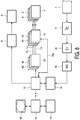
- Fig. 6 shows a block circuit diagram of the apparatus shown in Fig. 4 .
- the diagrammatically indicated pair of coils 3 (the suffixes a and b have been omitted from all the pairs of coils in Fig. 6 for the sake of simplicity) are supplied by a controllable current source 31 with d.c. current that can be controlled - and switched on and off - by a control unit 10.
- the control unit 10 cooperates with a workstation 12 that is provided with a monitor 13 for showing images representing the distribution of the particles in the region of action. Inputs can be made by a user via a keyboard or some other inputting unit 14.
- the pairs of coils 4, 5, 6 receive their currents from current amplifiers 41, 51 and 61.
- the waveforms over time of the currents Ix, Iy and Iz to be amplified, which currents generate the desired magnetic fields, are preset by respective waveform generators 42, 52 and 62.
- the waveform generators 42, 52, 62 are controlled by the control unit 10, which calculate the waveform over time required for the particular examination, investigation or treatment procedure and loads it into the waveform generators. In the course of the examination, investigation or treatment, these signals are read out from the waveform generators and fed to the amplifiers 41, 51, 61, which generate the currents required for the pairs of coils 4, 5 and 6 from them.
- the signals that are received by the coil 7 that is used when the object is being examined or investigated are fed to an amplifier 72 via a suitable filter 71.
- the output signals from the amplifier 72 are digitized by an analog-to-digital converter 73 and fed to an image-processing unit 74, which reconstructs the spatial distribution of the particles from the signals and from the position that the zone 301 is occupying at the time during the reception of the signals.
- the reader is referred at this point to D1 for an exact description of the reconstruction from the signals received by coil 7. From the reconstructed signals, an image is generated that is shown on the monitor 13 of the workstation 12.
- the apparatus can also be used for the local heating of the region of action.
- a shift of the zone 301 is produced for this purpose with the help of pairs of coils 4, 5 and 6, with the control unit 10 controlling the waveform generators 42, 52, 62 in the appropriate way.
- the shifting of the zone 301 for the purpose of determining the spatial distribution of magnetic particles (and, furthermore, for the reconstruction of image data) or for the purpose of local heating of the region of action, reference should be made to documents D1 and D2.
- Fig. 1 shows the flowchart for a first embodiment. It is assumed that the patient 1 has a dental filling of amalgam and is to be examined in the neck region. Under normal circumstances, the jaw region of the patient 1 will be situated in or in the immediate vicinity of the region of action during the examination, which means that the dental filling will be influenced by the temporally variable magnetic fields from the pairs of coils 4, 5 and 6. If an examination were being performed, this would cause eddy currents to be set up in the dental filling, as a result of which the filling would heat up and lasting damage might be done to the jaw region of the patient 1.
- the inductance of one of the inductive means belonging to the apparatus shown in Fig. 4 is determined in step M1.
- the inductive means is assumed to be the coil 4a, but it could equally well be any of the other coils shown.
- the (measured) inductance of a coil is known to depend on geometrical parameters and on the characteristics of the matter in the space within the coil or of the material situated therein. It is also known that, when a coil is supplied with electrical energy, the size of the inductance of the coil has an effect on the waveform of the current or voltage.
- the inductance of the coil 4a may, for example, be determined by applying a voltage pulse of square-wave form to the coil and analyzing the waveform over time of the resulting current.
- Another alternative for determining the inductance is to generate an alternating magnetic field with another coil of the apparatus shown in Fig. 4 , such as coil 4b, for example, which field will induce a current in coil 4a by reference to which statements can be made regarding the measured inductance of coil 4a.
- the parameters of the circuit are known to change if the inductance of the coil changes.
- the coil 4a is connected to an oscillating circuit whose impedance can be determined as a function of frequency. If the impedance of the oscillating circuit changes without there being any change to the other components of the oscillating circuit, then the inductance of the coil has changed. This method is also known from the prior art, and for that reason any description of further details will be dispensed with.
- the other components of the oscillating circuit are housed in the waveform generator 42, together with a measuring means for measuring the impedance Z M .
- the measurement of impedance is activated via the workstation 12 by means of the user control element 14.
- the workstation 12 causes the waveform generator 41 to automatically determine the frequency-dependent impedance Z M of the oscillating circuit and to transmit this value to the control unit 10.
- the control unit 10 is coupled to the waveform generator 41 via a separate bi-directional link I M .
- the impedance Z M measured is passed on by the control unit 10 to the workstation 12.
- the impedance Z M measured which is generally a complex value
- a reference impedance Z R which is usually complex likewise
- a (complex) difference in impedance ⁇ Z is determined.
- this can be done at many or all frequencies.
- this complex comparison may, however, also take place at only a few selected frequencies at which a large change may typically be expected.
- the reference impedance Z R in this case is that impedance of the oscillating circuit that is measured when there are no objects or other relevant items in the region of action.
- step M3 the difference in impedance ⁇ Z that has been determined is compared with a maximum permitted difference in impedance ⁇ Z MAX .
- This maximum permitted difference in impedance AZ MAX arises from the fact that the impedance of the oscillating circuit will be changed (though by only a minimal amount) even by objects having no interfering material being introduced into the region of action.
- a value can be determined for the difference in impedance ⁇ Z MAX that is the result of measurements made on a number of different patients, there being a patient having no interfering material and no magnetic materials situated in the region of action at the time of each measurement.
- step M4 If the different in impedance ⁇ Z determined is less than the maximum permitted difference in impedance ⁇ Z MAX , then no interfering material has been detected and subsequent treatment or a subsequent examination or investigation as in document D1 or D2 can be performed in step M4 without any reservations. If the difference in impedance ⁇ Z determined is more than the maximum permitted difference in impedance ⁇ Z MAX , then in a step M5 the user of the apparatus is informed by means of suitable forms of representation on the display unit 13. In the next step, M6, system parameters are changed by the workstation 12 in such a way that any heating-up of the interfering material or its surroundings that may be expected is reduced or avoided.
- reduced maximum values are, for example, given to the control unit 100 both for the magnetic fields and for the pattern followed by them over time.
- the control unit 10 controls the reduced currents through the pairs of coils 4 to 6 in line with the reduced field strengths preset for the magnetic fields by setting in each case the current level and a slowed waveform over time at the current amplifiers 42, 52 and 62 and the waveform generators 41, 51 and 61. Also, the field strength of the gradiented magnetic field from the pair of coils 3 is reduced by the controllable current source 31. If purposeful examination or treatment of the object is not possible even with the system set in this way, then the user can break off the examination or treatment at this point in order to remove the interfering material. For this reason, the arrow between steps M6 and M4 is shown dashed in Fig. 1 .
- the interfering material may be screened off from the apparatus shown in Fig. 4 .
- the user of the apparatus may, once the presence of the dental filling of amalgam has been detected, screen off the neck region of the patient 1.
- a magnetic metal screening plate is positioned between the jaw region of the patient 1 and the region of action of the apparatus shown in Fig. 4 . This reduces the effect of the temporally variable magnetic fields from the pairs of coils 4, 5 and 6 sufficiently for the heating-up to be reduced to an acceptable size.
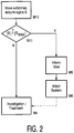
- Fig. 2 shows the flowchart for a second embodiment.
- interfering material is first detected in a step M10.
- the zone 301 is moved in space, as described in documents D1 and D2, but with a reduced spatial resolution so as not to heat up the interfering material during the detection thereof.
- the reduction in spatial resolution can be performed in various ways:
- the speed at which the zone 301 is moved may be reduced as well.
- the frequencies of the currents through the pairs of coils 4, 5 and 6 are reduced.
- ferromagnetic material in particular is influenced by temporally variable magnetic fields, as a result of which signals similar to those described in documents D1 and D2 for the influencing of magnetic particles are produced. These signals are thus received by the coil 7, are fed to the amplifier 72 via the filter 71, are digitized by the analog-to-digital converter 73 and are fed to the image processing unit 74. In step M11 the image processing unit 74 checks to see whether the magnitude
- S MAX is derived from the consideration that signals (though small ones) are received even when there is, in the region of action, a patient who does not have any interfering (ferromagnetic) material.
- the other steps M4, M5 and M6 correspond to those in Fig. 1 .
- Fig. 3 shows the flowchart of a third embodiment.
- magnetic particles have been administered to the patient beforehand.
- the first step M10 which corresponds to that in Fig. 2 , is performed.
- the received signals S make their way to the image-processing unit 74 after pre-processing.
- the image-processing unit 74 then performs, in step M12, a frequency analysis of the signals S by breaking them down into corresponding spectral components.
- the image-processing unit 74 supplies a reference spectrum that derives from signals from patients situated in the region of action who have had magnetic particles administered to them but do not have any interfering material. After any normalization that may be needed, the amounts of the individual frequency components in the signal measured are subtracted from those in the reference spectrum. When there is no interfering material present, the size of the difference is almost zero for every frequency component and step M4 can be performed.
- Steps M5 and M6 are performed in this case. Steps M4, M5 and M6 correspond to those in Fig. 1 and Fig. 2 .
- Ferromagnetic material behaves in a similar way to that in which it behaves in the method shown in Fig. 2 in that it generates signal components of its own.
- Interfering material in which eddy currents arise can be detected indirectly. With the opposing magnetic fields produced by the eddy currents, it influences surrounding magnetic particles in such a way that a change occurs in the amounts of individual spectral components in the signal measured. This change can be detected by the formation, as described above, of a difference from the reference spectrum.
Landscapes
- Health & Medical Sciences (AREA)
- Animal Behavior & Ethology (AREA)
- Biomedical Technology (AREA)
- Nuclear Medicine, Radiotherapy & Molecular Imaging (AREA)
- Radiology & Medical Imaging (AREA)
- Life Sciences & Earth Sciences (AREA)
- Engineering & Computer Science (AREA)
- General Health & Medical Sciences (AREA)
- Public Health (AREA)
- Veterinary Medicine (AREA)
- Magnetic Resonance Imaging Apparatus (AREA)
- Investigating Or Analyzing Materials By The Use Of Magnetic Means (AREA)
- Electrotherapy Devices (AREA)
- Magnetic Treatment Devices (AREA)
Description
- The invention relates to a method and an arrangement for influencing magnetic particles in a region of action.
- Magnetic particles are relatively easy to detect and can therefore be used for examinations and investigations (particularly medical ones). An apparatus and method of this kind for determining the spatial distribution of magnetic particles in an examination zone (i.e. a region of action), and the use therein of suitable magnetic particles, are described in German patent application
DE 101 51 778 A1 . This patent application will be referred to below as D1. To allow the spatial distribution of magnetic particles in an examination zone to be determined, a spatially inhomogeneous magnetic field is generated that has at least one zone in which the magnetization of the particles is in a state of non-saturation. Changing the position of this zone within the examination zone produces a change in magnetization that can be detected from the outside and that gives information on the spatial distribution of the magnetic particles in the examination zone. -
EP 1 304 542 A2 is a document falling under Article 54(3) EPC and claiming the priority of D1. - Magnetic particles can also be used to heat their surroundings, particularly in medical hyperthermia. A method and a system of this kind for the local heating of regions of an object by variation of the magnetization of magnetic or magnetizable substances is described in German patent application
DE 102 38 853 A1 . This patent application will be referred to below as D2. To heat the target region (i.e. the region of action) locally, an inhomogeneous magnetic field is generated having a pattern in space of its magnetic field strength such that a first sub-zone having a low magnetic field strength (the magnetic particles are not saturated in it) and a second sub-zone having a higher magnetic field strength are generated in the target region. The position in space of the two sub-zones in the target region is then changed for so long at a given frequency that the particles heat up to a desired temperature due to a frequent change in magnetization. - However, unwanted heating-up may possibly occur with the methods disclosed in D1 and D2.
-
US 2001/012915 A1 discloses a probe instrument using room-temperature sensor(s) that can measure magnetic susceptibilities variations. The instrument includes room temperature magnetic sensors, and detects the sample, that is the tissue response to an applied field coil. The sensors that can be used include magnetoresistive, fluxgate and magnetoinductive sensors. The applied field coil dimensions are chosen so that the applied field is optimized for maximum response from the item of interest while minimizing the effects due to the overlying tissue and at the same time not unduly increasing the sensitivity of the instrument to adjacent organs. To minimize noise introduced in the sensor due to fluctuations in the applied field, the applied field is canceled at the position of the sensor. To overcome variations in the sensor output due to fluctuations in the applied field, change in the ambient temperature and mechanical relaxation of the instrument, the detector assembly is oscillated while the examined patient remains stationary. -
DE 3813479 A1 discloses a device for accurately detecting and monitoring the position of an object inside biological tissue, particularly an endotracheal tube inside a patient's throat. -
US 6082366 A discloses a method and an arrangement for determining the position of a marker in an organic cavity, in particular for establishing local passage speeds within the framework of the medical diagnosis of the stomach-bowel tract. -
US 6541966 B1 discloses an apparatus for detecting a metal object. - It is therefore an object of the invention to develop a method by which it is possible for heating-up of this kind to be reduced or avoided, and to develop an apparatus with which this method can be performed.
- This object is achieved by a method as defined in claim 1, and an arrangement as defined in
claim 2. Preferred embodiments are defined in the dependent claims. The invention is based on the finding that, in performing the methods disclosed in D1 and D2, heating-up can be observed of items made of interfering material that are situated in or on the object being examined, investigated or treated. The heating-up may be so severe in this case that the object is damaged. Within the meaning of the invention, interfering material is ferromagnetic material and material having good conductivity for electrical current, and particularly metal or alloys thereof. If the object is a patient, then dental fillings of amalgam, artificial joints, rods or screws fitted in or on bones, or even items situated on the outside of the patient's body such as personal adornments (ear-rings, adornments in piercings) heat up. A planned examination or investigation or planned treatment by the methods disclosed in D1 and D2 may still be performed under certain circumstances if any possible heating-up during the examination, investigation or treatment is precluded by, for example, changing the system parameters, or if the interfering material is removed beforehand. - In a first step, any interfering material that may be present is detected. There are different possible ways of doing this. If interfering material is brought into the zone of influence of an inductive means, such as a coil, for example, there is a change in the resulting overall magnetic field. This is equivalent to a change in the measured inductance of the inductive means when the interfering material is brought into its zone of influence. This effect is made use of in the manner defined in (i) of
claim 2 to determine the presence of interfering material. On the one hand, known detectors may be used for this purpose. If one of the means used for influencing the magnetic particles is an inductive means, then, on the other hand, this inductive means may be used as a detector, as claimed inclaim 3. This saves on components for the apparatus and an apparatus for performing the method can be produced more economically. - Alternatively, the detection of interfering material may be performed as defined in (ii) and (iii) of
claim 2. For detection, steps of the method are performed that are similar to the steps that take place in the treatment, examination or investigation proper. It is, however, essential for care to be taken to see that the material does not heat up in a non-allowable way even during the detection itself. This can be achieved on the one hand by employing reduced spatial resolution, given that the measures by which spatial resolution is reduced also produce a reduction in the heating-up of interfering material. As can be seen from documents D1 and D2, spatial resolution may, for example, be reduced by reducing the strength of the magnetic field by which the two sub-zones are produced. So that the position in space of the two sub-zones cannot be changed in such a way as to leave the region of action, the amplitude of the field strength of the temporally variable magnetic fields by which the position in space of the two sub-zones is changed is reduced at the same time, which likewise and to an additional degree reduces the heating-up. Another measure for reducing spatial resolution is to use a coarser scanning grid during the changing of the position in space of the sub-zones. On the other hand, non-allowable heating up during the detection may also be precluded by performing the change in the position in space of the two sub-zones more slowly than in the examination or treatment. - The measures just mentioned have another beneficial effect: static and dynamic forces that the magnetic fields exert on the interfering material are also reduced. This is of interest if, for example, the object is a patient in whom there is a piece of shrapnel from a bomb and who, as a result of an excessively high field strength for the magnetic fields and of the forces resulting therefrom, might move onto the piece of shrapnel. A method, wherein the magnetic particles are not introduced into the object until after the detection, which does not form part of the present invention, is used particularly to detect ferromagnetic material. Since, in the detection, there are no magnetic particles contained in the object, the signals detected originate solely from the interfering material. In accordance with
claim 4, it is possible for the actual examination or treatment of the object to be performed immediately following the detection of the interfering material, thus producing a more efficient sequence for the method. If there are both magnetic particles and interfering material present in the object, then, as defined inclaim 5, it is seen from an examination of the spectrum of the signal acquired that the spectrum contains spectral components which derive from the magnetic particles and also spectral components which derive from the interfering material. - To obtain evidence of interfering material, the known spectral components for the magnetic particles are, for example, subtracted from the overall spectrum of the signal acquired, thus leaving the spectral components for the interfering material and enabling the conclusion to be drawn that the latter is at least present.
- If interfering material has been detected, then it should be removed if at all possible. If this is not possible, then, to protect the object, a planned examination or planned treatment may have to be abandoned if necessary. If an examination or treatment is still to be performed in spite of the fact that interfering material is present in the vicinity of the region of action, the risk of non-allowable heating-up can be avoided by taking suitable measures. The interfering material may, for example, be actively screened off with a local opposing magnetic field or may be passively screened off (such as with metal screening plates). In this way, the influence of the temporally variable magnetic fields on the interfering material is reduced to such a degree that the interfering material does not heat up or does not interfere with the treatment or examination. As an alternative or in addition, the features of
claim 6 may be provided, wherein, for example, the frequency of the temporally variable magnetic fields used is reduced. This can be done automatically by a suitable arrangement. Excessive heating-up can also be avoided in accordance withclaim 7. The lower spatial resolution may, for example, be obtained by reducing the strength of the magnetic field or by causing the change in the position in space of the two sub-zones to take place in a coarser scanning grid. This can also be done automatically by an appropriate change in system parameters. As a result of the lower strengths of the magnetic fields used and of the slowed pattern they follow with time, the interfering material is influenced to such a small degree that any excessive heating-up is ruled out. - As well as the possible heating-up of interfering material, there is another unwanted effect that has shown up in other examinations: if interfering material finds its way into the zone of influence of an external magnetic field, then an opposing magnetic field forms in and/or around the interfering material, as a result of eddy currents or magnetization, for example, which opposing magnetic field superimposes itself on the external magnetic field to form an overall magnetic field. The field-line pattern of this overall magnetic field is different from that of the external magnetic field, as a result of which the position in space of the two sub-zones changes or in other words shifts or is displaced uncontrollably. However, for the magnetic particles to be influenced in a targeted fashion, it is necessary for the exact position of the sub-zones to be known. This knowledge that is needed of the current positions in space of the two sub-zones is thus only limited or does not exist at all, which has an adverse effect on the accuracy and success of the treatment or examination. The detection of the interfering material thus not only enables action to be taken in response to unwanted heating-up but also allows a user to be directed to a possible inaccuracy in the system.
- These and other aspects of the invention are apparent from and will be elucidated with reference to the embodiments described hereinafter.
- In the drawings:
-
Fig. 1 is a flowchart for a first embodiment of the invention. -
Fig. 2 is a flowchart for a second embodiment of the invention. -
Fig. 3 is a flowchart for a third embodiment of the invention. -
Fig. 4 shows an apparatus for performing the method according to the present disclosure. -
Fig. 5 shows the pattern of field lines generated by the coils contained in the apparatus. -
Fig. 6 is a block circuit diagram of the arrangement shown inFig. 4 . - An apparatus for performing the method according to the present disclosure is shown in
Fig. 4 . In the Figure, reference numeral 1 refers to the object for examination or investigation, a patient in this case, who is situated on a patent presentation table of which only theplate 2 is indicated. Situated above and below the patient 1 and theplate 2 of the table, there are also a plurality of pairs of coils, whose region of action defines the examination zone. A first pair ofcoils 3 comprises the twowindings Fig. 5 by means of the field lines 300. Its gradient in the direction of the vertical axis of the pair of coils is almost constant and at one point along this axis it reaches a value of zero. Starting from this field-free point, the strength of the magnetic fields increases in all three directions in space with increasing distance from the point. In a zone 301 (the first sub-zone) around the field-free point, which zone is indicated by a dashed line, the field strength is so low that the magnetization of magnetic particles situated in it is not saturated, whereas outside thezone 301 it is in a state of saturation. In the remaining zone outside 301 (the second sub-zone 302), the magnetization of the particles is in a state of saturation. - If a further magnetic field is superimposed on the gradiented magnetic field in the region of action, then the
zone 301 shifts in the direction of this further magnetic field, the size of the shift increasing with the strength of the magnetic field. If the magnetic field superimposed is temporally variable, then the position ofzone 301 changes with time and in space accordingly. There are three further pairs ofcoils windings - Finally, there is also shown in
Fig. 4 afurther coil 7, the purpose of which is to detect signals generated in the examination zone. In principle, any of the pairs of field-generatingcoils 3 to 6 could be used for this purpose. There are, however, advantages in using a separate receiving coil. A better signal-to-noise ratio is obtained (particularly if a plurality of receiving coils are used), and the coil can be so arranged and switched that it is decoupled from other coils. -
Fig. 6 shows a block circuit diagram of the apparatus shown inFig. 4 . The diagrammatically indicated pair of coils 3 (the suffixes a and b have been omitted from all the pairs of coils inFig. 6 for the sake of simplicity) are supplied by a controllablecurrent source 31 with d.c. current that can be controlled - and switched on and off - by acontrol unit 10. Thecontrol unit 10 cooperates with aworkstation 12 that is provided with amonitor 13 for showing images representing the distribution of the particles in the region of action. Inputs can be made by a user via a keyboard or someother inputting unit 14. - The pairs of
coils current amplifiers respective waveform generators waveform generators control unit 10, which calculate the waveform over time required for the particular examination, investigation or treatment procedure and loads it into the waveform generators. In the course of the examination, investigation or treatment, these signals are read out from the waveform generators and fed to theamplifiers coils - Generally speaking, a non-linear relationship exists between the shift of the
zone 301 from its position at the center of thegradient coil arrangement 3 and the current through the gradient coil arrangement. Moreover, all three coils must generally generate a magnetic field if thezone 301 is to be shifted along a straight line extending off the center. Where the waveform of the currents with time is preset, this is allowed for by the control unit, with the help of suitable tables, for example. Thezone 301 can therefore be shifted through the region of action along paths of any desired shape. - The signals that are received by the
coil 7 that is used when the object is being examined or investigated are fed to anamplifier 72 via asuitable filter 71. The output signals from theamplifier 72 are digitized by an analog-to-digital converter 73 and fed to an image-processingunit 74, which reconstructs the spatial distribution of the particles from the signals and from the position that thezone 301 is occupying at the time during the reception of the signals. The reader is referred at this point to D1 for an exact description of the reconstruction from the signals received bycoil 7. From the reconstructed signals, an image is generated that is shown on themonitor 13 of theworkstation 12. - As an alternative to examination or investigation, the apparatus can also be used for the local heating of the region of action. In a similar way to the imaging, a shift of the
zone 301 is produced for this purpose with the help of pairs ofcoils control unit 10 controlling thewaveform generators zone 301 for the purpose of determining the spatial distribution of magnetic particles (and, furthermore, for the reconstruction of image data) or for the purpose of local heating of the region of action, reference should be made to documents D1 and D2. -
Fig. 1 shows the flowchart for a first embodiment. It is assumed that the patient 1 has a dental filling of amalgam and is to be examined in the neck region. Under normal circumstances, the jaw region of the patient 1 will be situated in or in the immediate vicinity of the region of action during the examination, which means that the dental filling will be influenced by the temporally variable magnetic fields from the pairs ofcoils - Therefore, before the actual examination or treatment of the patient 1, the inductance of one of the inductive means belonging to the apparatus shown in
Fig. 4 is determined in step M1. The inductive means is assumed to be thecoil 4a, but it could equally well be any of the other coils shown. Generally speaking, the (measured) inductance of a coil is known to depend on geometrical parameters and on the characteristics of the matter in the space within the coil or of the material situated therein. It is also known that, when a coil is supplied with electrical energy, the size of the inductance of the coil has an effect on the waveform of the current or voltage. These interrelationships will not be gone into in detail here because they are part of the general knowledge of the man skilled in the art. Hence, the inductance of thecoil 4a may, for example, be determined by applying a voltage pulse of square-wave form to the coil and analyzing the waveform over time of the resulting current. Another alternative for determining the inductance is to generate an alternating magnetic field with another coil of the apparatus shown inFig. 4 , such ascoil 4b, for example, which field will induce a current incoil 4a by reference to which statements can be made regarding the measured inductance ofcoil 4a. - If, generally speaking, a coil is incorporated in an oscillating circuit, the parameters of the circuit are known to change if the inductance of the coil changes. With this alternative, which is made use of in the apparatus being elucidated here, the
coil 4a is connected to an oscillating circuit whose impedance can be determined as a function of frequency. If the impedance of the oscillating circuit changes without there being any change to the other components of the oscillating circuit, then the inductance of the coil has changed. This method is also known from the prior art, and for that reason any description of further details will be dispensed with. Apart from thecoil 4a, the other components of the oscillating circuit are housed in thewaveform generator 42, together with a measuring means for measuring the impedance ZM. To allow interfering material to be detected, the measurement of impedance is activated via theworkstation 12 by means of theuser control element 14. Via thecontrol unit 10, theworkstation 12 causes thewaveform generator 41 to automatically determine the frequency-dependent impedance ZM of the oscillating circuit and to transmit this value to thecontrol unit 10. For this purpose, thecontrol unit 10 is coupled to thewaveform generator 41 via a separate bi-directional link IM. The impedance ZM measured is passed on by thecontrol unit 10 to theworkstation 12. - In the next step M2, the impedance ZM measured, which is generally a complex value, is compared with a reference impedance ZR, which is usually complex likewise, and a (complex) difference in impedance ΔZ is determined. Depending on the computing power of the
workstation 12, this can be done at many or all frequencies. To reduce the computing work, this complex comparison may, however, also take place at only a few selected frequencies at which a large change may typically be expected. The reference impedance ZR in this case is that impedance of the oscillating circuit that is measured when there are no objects or other relevant items in the region of action. - In step M3, the difference in impedance ΔZ that has been determined is compared with a maximum permitted difference in impedance ΔZMAX. This maximum permitted difference in impedance AZMAX arises from the fact that the impedance of the oscillating circuit will be changed (though by only a minimal amount) even by objects having no interfering material being introduced into the region of action. For patients, for example, a value can be determined for the difference in impedance ΔZMAX that is the result of measurements made on a number of different patients, there being a patient having no interfering material and no magnetic materials situated in the region of action at the time of each measurement.
- If the different in impedance ΔZ determined is less than the maximum permitted difference in impedance ΔZMAX, then no interfering material has been detected and subsequent treatment or a subsequent examination or investigation as in document D1 or D2 can be performed in step M4 without any reservations. If the difference in impedance ΔZ determined is more than the maximum permitted difference in impedance ΔZMAX, then in a step M5 the user of the apparatus is informed by means of suitable forms of representation on the
display unit 13. In the next step, M6, system parameters are changed by theworkstation 12 in such a way that any heating-up of the interfering material or its surroundings that may be expected is reduced or avoided. For this purpose, reduced maximum values are, for example, given to the control unit 100 both for the magnetic fields and for the pattern followed by them over time. Thecontrol unit 10 controls the reduced currents through the pairs ofcoils 4 to 6 in line with the reduced field strengths preset for the magnetic fields by setting in each case the current level and a slowed waveform over time at thecurrent amplifiers waveform generators coils 3 is reduced by the controllablecurrent source 31. If purposeful examination or treatment of the object is not possible even with the system set in this way, then the user can break off the examination or treatment at this point in order to remove the interfering material. For this reason, the arrow between steps M6 and M4 is shown dashed inFig. 1 . - An alternative to this is for the interfering material to be screened off from the apparatus shown in
Fig. 4 . For the above-mentioned examination of the neck region of the patient 1, the user of the apparatus may, once the presence of the dental filling of amalgam has been detected, screen off the neck region of the patient 1. For this purpose, a magnetic metal screening plate is positioned between the jaw region of the patient 1 and the region of action of the apparatus shown inFig. 4 . This reduces the effect of the temporally variable magnetic fields from the pairs ofcoils -
Fig. 2 shows the flowchart for a second embodiment. Here too, interfering material is first detected in a step M10. For this purpose, thezone 301 is moved in space, as described in documents D1 and D2, but with a reduced spatial resolution so as not to heat up the interfering material during the detection thereof. The reduction in spatial resolution can be performed in various ways: - The gradiented magnetic field from pair of
coils 3 is reduced, as a result of which the spatial extent ofzone 301 is enlarged. - The magnetic fields from the pairs of
coils zone 301 passes through substantially smaller areas of the region of action than is the case at the time of an examination or treatment. This corresponds to an enlargement of the scanning grid. - In addition, the speed at which the
zone 301 is moved may be reduced as well. For this purpose, the frequencies of the currents through the pairs ofcoils - Initially, there is in the apparatus in
Fig.4 a patient to whom no magnetic particles have, as yet, been administered. If thezone 301 is now moved within the region of action, then ferromagnetic material in particular is influenced by temporally variable magnetic fields, as a result of which signals similar to those described in documents D1 and D2 for the influencing of magnetic particles are produced. These signals are thus received by thecoil 7, are fed to theamplifier 72 via thefilter 71, are digitized by the analog-to-digital converter 73 and are fed to theimage processing unit 74. In step M11 theimage processing unit 74 checks to see whether the magnitude |S| of the signals exceeds a given threshold value |SMAX|. In this case too, the threshold value |SMAX| is derived from the consideration that signals (though small ones) are received even when there is, in the region of action, a patient who does not have any interfering (ferromagnetic) material. The other steps M4, M5 and M6 correspond to those inFig. 1 . -
Fig. 3 shows the flowchart of a third embodiment. In this case magnetic particles have been administered to the patient beforehand. To allow interfering material to be detected, the first step M10, which corresponds to that inFig. 2 , is performed. - In this case too, the received signals S make their way to the image-processing
unit 74 after pre-processing. The image-processingunit 74 then performs, in step M12, a frequency analysis of the signals S by breaking them down into corresponding spectral components. For the comparison that takes place in the next step, M13, the image-processingunit 74 supplies a reference spectrum that derives from signals from patients situated in the region of action who have had magnetic particles administered to them but do not have any interfering material. After any normalization that may be needed, the amounts of the individual frequency components in the signal measured are subtracted from those in the reference spectrum. When there is no interfering material present, the size of the difference is almost zero for every frequency component and step M4 can be performed. When there is interfering material present, then there are remainders at least for particular frequency components that originate from the interfering material. Steps M5 and M6 are performed in this case. Steps M4, M5 and M6 correspond to those inFig. 1 andFig. 2 . - With the method shown in
Fig. 3 , it is possible for any interfering material to be detected. Ferromagnetic material, for example, behaves in a similar way to that in which it behaves in the method shown inFig. 2 in that it generates signal components of its own. Interfering material in which eddy currents arise can be detected indirectly. With the opposing magnetic fields produced by the eddy currents, it influences surrounding magnetic particles in such a way that a change occurs in the amounts of individual spectral components in the signal measured. This change can be detected by the formation, as described above, of a difference from the reference spectrum.
Claims (10)
- A method for influencing, in a region of action, magnetic particles that have been introduced into an object prior to the implementation of this method, which method has the following steps:a) detection of interfering material in or on the object,b) generation of a magnetic field having a pattern in space of its magnetic field strength such that a first sub-zone (301) having a low magnetic field strength where the magnetization of the magnetic particles is not saturated and a second sub-zone (302) having a higher magnetic field strength where the magnetization of the magnetic particles is saturated are formed in the region of action,c) changing the position in space of the two sub-zones in the region of action so that the magnetization of the particles changes locally,d) acquiring signals that depend on the magnetization in the region of action, which magnetization is influenced by the above change in position;wherein, for the detection in step a), steps b) to d) are performed for a first time with a lower spatial resolution and/or at a lower speed, and the signals acquired are analyzed to obtain information at least on the presence of interfering material, and wherein, in the analysis, the signals acquired are examined for signal components that derive from interfering material.
- An arrangement for influencing magnetic particles in a region of action, which arrangement has:a) means for detecting interfering material,b) means for generating a magnetic field having a pattern in space of its magnetic field strength such that a first sub-zone (301) having a low magnetic field strength where the magnetization of the magnetic particles is not saturated and a second sub-zone (302) having a higher magnetic field strength where the magnetization of the magnetic particles is saturated are formed in the region of action,c) means for changing the position in space of the two sub-zones in the region of action so that the magnetization of the particles changes locally,d) means for acquiring signals, which signals depend on the magnetization in the region of action that is influenced by the change in the position in space of the sub-zones;wherein the means for detecting interfering material either:(i) comprise an inductive means and are arranged to, before the introduction of the magnetic particles into the object, perform a measurement of the change in the inductance of the inductive means that is the result of a change in the distance between the object and the inductive means; or(ii) are arranged to analyse signals to obtain information at least on the presence of interfering material, in case the magnetic particles are introduced into the object before this detection, wherein those signals have been acquired by operating generating means b), changing means c) and acquiring means d) arranged to be implemented for a first time with a lower spatial resolution and/or at a lower speed;(iii) comprise an image-processing unit configured to, before the introduction of the magnetic particles into the object, check whether the magnitude of signals acquired by operating generating means b), changing means c) and acquiring means d) for a first time with a lower spatial resolution exceeds a given threshold.
- An arrangement as claimed in claim 2, wherein, when comprising the features in (i), the inductive means is one of those means that are used in the generation of the magnetic field, in the change in the position in space of the sub-zones and, where applicable, in the acquisition of the signals.
- An arrangement as claimed in claim 2, wherein, in the analysis of features in (ii), the detection means are arranged such that the signals acquired are examined for signal components that derive from interfering material.
- An arrangement as claimed in claim 4, when comprising the features in (ii), wherein the detection means are arranged such that the interfering material is detected from the spectral composition of the signals acquired.
- An arrangement as claimed in any of the claims 2 to 5, wherein, if interfering material is present, the arrangement is arranged such that magnetic fields having a reduced temporal variation are used during the influencing of the magnetic particles to change the position in space of the two sub-zones.
- An arrangement as claimed in any of the claims 2 to 6, wherein, if interfering material is present, generating means b) and positioning means c) are arranged to be operated with a reduced spatial resolution during the influencing of the magnetic particles.
- An arrangement as claimed in claim 2, having a measuring means for measuring the inductance of at least one of the inductive means that are used for the generation of the magnetic field, for the change in the position in space of the sub-zones and/or for the acquisition of the signals.
- An arrangement as claimed in claim 2, wherein the detection means in a) comprises an image-processing unit (74) configured to perform a frequency analysis of the signals and to compare the resulting frequency components with those of a reference spectrum derived from patients having had magnetic particles administered to them but not having any interfering material.
- An arrangement as claimed in claim 9, wherein the analyzing unit is further configured to examine the signals acquired for signal components deriving from magnetic particles.
Priority Applications (1)
| Application Number | Priority Date | Filing Date | Title |
|---|---|---|---|
| EP04725750.6A EP1615554B1 (en) | 2003-04-15 | 2004-04-05 | Method and arrangement for influencing magnetic particles and detecting interfering material |
Applications Claiming Priority (3)
| Application Number | Priority Date | Filing Date | Title |
|---|---|---|---|
| EP03101012 | 2003-04-15 | ||
| EP04725750.6A EP1615554B1 (en) | 2003-04-15 | 2004-04-05 | Method and arrangement for influencing magnetic particles and detecting interfering material |
| PCT/IB2004/001119 WO2004091392A1 (en) | 2003-04-15 | 2004-04-05 | Method and arrangement for influencing magnetic particles and detecting interfering material |
Publications (2)
| Publication Number | Publication Date |
|---|---|
| EP1615554A1 EP1615554A1 (en) | 2006-01-18 |
| EP1615554B1 true EP1615554B1 (en) | 2017-12-20 |
Family
ID=33185918
Family Applications (1)
| Application Number | Title | Priority Date | Filing Date |
|---|---|---|---|
| EP04725750.6A Expired - Lifetime EP1615554B1 (en) | 2003-04-15 | 2004-04-05 | Method and arrangement for influencing magnetic particles and detecting interfering material |
Country Status (4)
| Country | Link |
|---|---|
| US (1) | US7370656B2 (en) |
| EP (1) | EP1615554B1 (en) |
| JP (1) | JP4639185B2 (en) |
| WO (1) | WO2004091392A1 (en) |
Families Citing this family (48)
| Publication number | Priority date | Publication date | Assignee | Title |
|---|---|---|---|---|
| US7998062B2 (en) | 2004-03-29 | 2011-08-16 | Superdimension, Ltd. | Endoscope structures and techniques for navigating to a target in branched structure |
| JP5010914B2 (en) * | 2003-04-15 | 2012-08-29 | コーニンクレッカ フィリップス エレクトロニクス エヌ ヴィ | Method for determining spatial distribution of magnetic particles and composition for administering magnetic particles |
| EP2316328B1 (en) * | 2003-09-15 | 2012-05-09 | Super Dimension Ltd. | Wrap-around holding device for use with bronchoscopes |
| ATE438335T1 (en) * | 2003-09-15 | 2009-08-15 | Super Dimension Ltd | SYSTEM OF ACCESSORIES FOR USE WITH BRONCHOSCOPES |
| US8764725B2 (en) | 2004-02-09 | 2014-07-01 | Covidien Lp | Directional anchoring mechanism, method and applications thereof |
| CN100527168C (en) * | 2004-12-14 | 2009-08-12 | 皇家飞利浦电子股份有限公司 | Method for determining the spatial distribution of magnetic particles |
| US9129359B2 (en) * | 2006-11-10 | 2015-09-08 | Covidien Lp | Adaptive navigation technique for navigating a catheter through a body channel or cavity |
| CN101568294A (en) * | 2006-12-20 | 2009-10-28 | 皇家飞利浦电子股份有限公司 | Arrangement and method for influencing and/or detecting magnetic particles in a region of action |
| CN101573071B (en) * | 2006-12-20 | 2012-08-29 | 皇家飞利浦电子股份有限公司 | Device and method for influencing and/or detecting magnetic particles in a region of action |
| WO2008078276A1 (en) * | 2006-12-20 | 2008-07-03 | Philips Intellectual Property & Standards Gmbh | Arrangement and method for detecting and/or locating a magnetic material in a region of action, use of an arrangement in the examination of buildings |
| EP2091414B1 (en) | 2006-12-20 | 2016-07-06 | Philips Intellectual Property & Standards GmbH | Arrangement and method for influencing and/or detecting magnetic particles in a region of action |
| US20080167639A1 (en) * | 2007-01-08 | 2008-07-10 | Superdimension Ltd. | Methods for localized intra-body treatment of tissue |
| EP2124715A2 (en) * | 2007-01-24 | 2009-12-02 | Koninklijke Philips Electronics N.V. | Method for influencing and/or detecting magnetic particles in a region of action, magnetic particles and the use of magnetic particles |
| JP5100212B2 (en) | 2007-06-15 | 2012-12-19 | 株式会社東芝 | Magnetic particle imaging apparatus, detection coil arrangement method, and magnetic flux detection apparatus |
| US10292619B2 (en) * | 2007-07-09 | 2019-05-21 | Covidien Lp | Patient breathing modeling |
| US8905920B2 (en) | 2007-09-27 | 2014-12-09 | Covidien Lp | Bronchoscope adapter and method |
| EP2231273A2 (en) * | 2007-12-13 | 2010-09-29 | Koninklijke Philips Electronics N.V. | Arrangement and method for influencing and/or detecting magnetic particles in a region of action |
| JP5172384B2 (en) * | 2008-02-25 | 2013-03-27 | 株式会社東芝 | Imaging device |
| WO2009148668A2 (en) * | 2008-03-07 | 2009-12-10 | California Institute Of Technology | Effective-inductance-change based magnetic particle sensing |
| WO2009122273A2 (en) | 2008-04-03 | 2009-10-08 | Superdimension, Ltd. | Magnetic interference detection system and method |
| US8218846B2 (en) * | 2008-05-15 | 2012-07-10 | Superdimension, Ltd. | Automatic pathway and waypoint generation and navigation method |
| EP2297673B1 (en) | 2008-06-03 | 2020-04-22 | Covidien LP | Feature-based registration method |
| US8218847B2 (en) | 2008-06-06 | 2012-07-10 | Superdimension, Ltd. | Hybrid registration method |
| US8932207B2 (en) | 2008-07-10 | 2015-01-13 | Covidien Lp | Integrated multi-functional endoscopic tool |
| JP5667072B2 (en) * | 2008-12-10 | 2015-02-12 | コーニンクレッカ フィリップス エヌ ヴェ | Apparatus with variable selected field orientation for magnetic particle imaging |
| US9599591B2 (en) | 2009-03-06 | 2017-03-21 | California Institute Of Technology | Low cost, portable sensor for molecular assays |
| US8611984B2 (en) | 2009-04-08 | 2013-12-17 | Covidien Lp | Locatable catheter |
| RU2550660C2 (en) * | 2009-09-14 | 2015-05-10 | Конинклейке Филипс Электроникс Н.В. | Device and method of non-invasive intracardial electrocardiography with formation of image with application of magnetic particles |
| JP5650248B2 (en) | 2010-02-01 | 2015-01-07 | コビディエン エルピー | Region expansion algorithm |
| US10582834B2 (en) | 2010-06-15 | 2020-03-10 | Covidien Lp | Locatable expandable working channel and method |
| US10952593B2 (en) | 2014-06-10 | 2021-03-23 | Covidien Lp | Bronchoscope adapter |
| US10426555B2 (en) | 2015-06-03 | 2019-10-01 | Covidien Lp | Medical instrument with sensor for use in a system and method for electromagnetic navigation |
| US10478254B2 (en) | 2016-05-16 | 2019-11-19 | Covidien Lp | System and method to access lung tissue |
| US10751126B2 (en) | 2016-10-28 | 2020-08-25 | Covidien Lp | System and method for generating a map for electromagnetic navigation |
| US10418705B2 (en) | 2016-10-28 | 2019-09-17 | Covidien Lp | Electromagnetic navigation antenna assembly and electromagnetic navigation system including the same |
| US10722311B2 (en) | 2016-10-28 | 2020-07-28 | Covidien Lp | System and method for identifying a location and/or an orientation of an electromagnetic sensor based on a map |
| US10792106B2 (en) | 2016-10-28 | 2020-10-06 | Covidien Lp | System for calibrating an electromagnetic navigation system |
| US10446931B2 (en) | 2016-10-28 | 2019-10-15 | Covidien Lp | Electromagnetic navigation antenna assembly and electromagnetic navigation system including the same |
| US10615500B2 (en) | 2016-10-28 | 2020-04-07 | Covidien Lp | System and method for designing electromagnetic navigation antenna assemblies |
| US10638952B2 (en) | 2016-10-28 | 2020-05-05 | Covidien Lp | Methods, systems, and computer-readable media for calibrating an electromagnetic navigation system |
| US10517505B2 (en) | 2016-10-28 | 2019-12-31 | Covidien Lp | Systems, methods, and computer-readable media for optimizing an electromagnetic navigation system |
| US10295238B2 (en) * | 2017-02-14 | 2019-05-21 | Heatcraft Refrigeration Products Llc | Cooling system |
| US10352605B2 (en) * | 2017-02-14 | 2019-07-16 | Heatcraft Refrigerator Products, LLC | Cooling system with intermediate heat exchange fluid loop |
| CN109320226A (en) * | 2017-08-01 | 2019-02-12 | 崔光浩 | The beneficial natural mineral matter health mat and preparation method thereof of a kind of pair of human body |
| US11219489B2 (en) | 2017-10-31 | 2022-01-11 | Covidien Lp | Devices and systems for providing sensors in parallel with medical tools |
| EP3938035A1 (en) * | 2019-03-13 | 2022-01-19 | Magnetic Insight, Inc. | Magnetic particle actuation |
| US12672836B2 (en) | 2022-07-21 | 2026-07-07 | Covidien Lp | Handling respiration during navigational bronchoscopy |
| TR2022018221A2 (en) | 2022-11-30 | 2024-06-21 | Aselsan Elektronik Sanayi Ve Ticaret As | A MAGNETIC FIELD MEASURING DEVICE FOR DETECTION OR IMAGING OF MAGNETIC PARTICLES |
Citations (1)
| Publication number | Priority date | Publication date | Assignee | Title |
|---|---|---|---|---|
| EP1304542A2 (en) * | 2001-10-19 | 2003-04-23 | Philips Corporate Intellectual Property GmbH | Method for Determining the spacial distribution of magnetic particles |
Family Cites Families (12)
| Publication number | Priority date | Publication date | Assignee | Title |
|---|---|---|---|---|
| DK312884A (en) | 1984-06-27 | 1985-12-28 | Joergen Bach Andersen | APPLICATOR |
| GB2204133A (en) | 1987-04-21 | 1988-11-02 | Mccormick Lab Inc | A device for accurately detecting the position of a ferromagnetic material inside biological tissue |
| US5842986A (en) | 1995-08-16 | 1998-12-01 | Proton Sciences Corp. | Ferromagnetic foreign body screening method and apparatus |
| DE19532676C1 (en) | 1995-09-05 | 1997-05-07 | Inst Physikalische Hochtech Ev | Arrangement for determining the position of a marker in a cavity within the organism of a living being |
| GB9614139D0 (en) * | 1996-07-05 | 1996-09-04 | Nycomed Imaging As | Method |
| AUPP008197A0 (en) | 1997-10-29 | 1997-11-20 | Paragon Medical Limited | Improved targeted hysteresis hyperthermia as a method for treating diseased tissue |
| GB9813889D0 (en) | 1998-06-27 | 1998-08-26 | Secr Defence | Apparatus for detecting metals |
| US6470220B1 (en) * | 1999-03-29 | 2002-10-22 | The Regents Of The University Of California | Diagnosis and treatment of cancers using in vivo magnetic domains |
| DE19937493C2 (en) | 1999-08-07 | 2001-06-07 | Mfh Hyperthermiesysteme Gmbh | Magnetic field applicator for heating magnetic or magnetizable substances or solids in biological tissue |
| DE19958408A1 (en) * | 1999-12-02 | 2001-06-07 | Philips Corp Intellectual Pty | Magnetic resonance arrangement with devices to localize or visualize instrument inserted in patient; has magnet device controlled and positioned by control unit, to vary position in MRI datasets |
| US6997863B2 (en) * | 2001-07-25 | 2006-02-14 | Triton Biosystems, Inc. | Thermotherapy via targeted delivery of nanoscale magnetic particles |
| DE10238853A1 (en) | 2002-08-24 | 2004-03-04 | Philips Intellectual Property & Standards Gmbh | Process for local heating with magnetic particles |
-
2004
- 2004-04-05 WO PCT/IB2004/001119 patent/WO2004091392A1/en not_active Ceased
- 2004-04-05 US US10/552,801 patent/US7370656B2/en not_active Expired - Lifetime
- 2004-04-05 JP JP2006506464A patent/JP4639185B2/en not_active Expired - Fee Related
- 2004-04-05 EP EP04725750.6A patent/EP1615554B1/en not_active Expired - Lifetime
Patent Citations (1)
| Publication number | Priority date | Publication date | Assignee | Title |
|---|---|---|---|---|
| EP1304542A2 (en) * | 2001-10-19 | 2003-04-23 | Philips Corporate Intellectual Property GmbH | Method for Determining the spacial distribution of magnetic particles |
Also Published As
| Publication number | Publication date |
|---|---|
| JP2006524081A (en) | 2006-10-26 |
| JP4639185B2 (en) | 2011-02-23 |
| US7370656B2 (en) | 2008-05-13 |
| US20070007486A1 (en) | 2007-01-11 |
| WO2004091392A1 (en) | 2004-10-28 |
| EP1615554A1 (en) | 2006-01-18 |
Similar Documents
| Publication | Publication Date | Title |
|---|---|---|
| US7370656B2 (en) | Method and arrangement for influencing magnetic particles and detecting interfering material | |
| JP5542936B2 (en) | Apparatus and method for determining at least one electromagnetic quantity | |
| DE69224192T2 (en) | Apparatus and method for the visual representation of the structure of diamagnetic and paramagnetic objects | |
| JP5608236B2 (en) | Apparatus and method for detecting and / or detecting magnetic particles in an imaging region | |
| EP1615553B1 (en) | Arrangement for influencing magnetic particles | |
| EP2790574B1 (en) | Removal of background in mpi | |
| JP5718228B2 (en) | Magnetic resonance imaging apparatus and eddy current compensation method | |
| EP3111837A1 (en) | Image generating device, conductivity acquiring device, image generating method, and program | |
| RU2524974C2 (en) | Device and method for measurement of local liquid velocity | |
| CN101268941B (en) | Magnetic resonance method and apparatus for automatically determining objects that attenuate penetrating radiation | |
| JPH08206096A (en) | How to detect the presence of ferromagnetic objects in animals | |
| CN104825155A (en) | Analog cancellation of mri sequencing noise appearing in an ecg signal | |
| EP2906118B1 (en) | Dynamic background correction in mpi | |
| JP2006296809A (en) | Acupuncture point evaluation device | |
| CN103260508B (en) | For affecting and/or detect the apparatus and method of magnetic particle | |
| Yang et al. | A DSP-based EIT system with adaptive boundary voltage acquisition | |
| JP5642184B2 (en) | Apparatus for non-invasive intracardiac electrocardiography using MPI and method for operating the same | |
| Heugel et al. | EEG and fMRI coupling and decoupling based on joint independent component analysis (jICA) | |
| JP3547520B2 (en) | Magnetic resonance imaging system | |
| JP2002253524A (en) | Magnetic resonance imaging device | |
| JP2005137910A (en) | Eye monitoring device, visual field coil device, method of using rectangular coil, inspection device, guided orientation measurement method, and subject imaging method | |
| JP3237964B2 (en) | Inspection device using magnetic resonance | |
| JP2019502485A (en) | Subsequent MRI configuration dependent eddy current compensation | |
| JP2018511412A (en) | System and morphological probe for non-invasive real-time magnetic resonance analysis of body tissue | |
| JP4822399B2 (en) | Medical diagnostic imaging equipment |
Legal Events
| Date | Code | Title | Description |
|---|---|---|---|
| PUAI | Public reference made under article 153(3) epc to a published international application that has entered the european phase |
Free format text: ORIGINAL CODE: 0009012 |
|
| 17P | Request for examination filed |
Effective date: 20051115 |
|
| AK | Designated contracting states |
Kind code of ref document: A1 Designated state(s): AT BE BG CH CY CZ DE DK EE ES FI FR GB GR HU IE IT LI LU MC NL PL PT RO SE SI SK TR |
|
| AX | Request for extension of the european patent |
Extension state: AL HR LT LV MK |
|
| DAX | Request for extension of the european patent (deleted) | ||
| RAP1 | Party data changed (applicant data changed or rights of an application transferred) |
Owner name: PHILIPS INTELLECTUAL PROPERTY & STANDARDS GMBH Owner name: KONINKLIJKE PHILIPS ELECTRONICS N.V. |
|
| 17Q | First examination report despatched |
Effective date: 20110228 |
|
| RAP1 | Party data changed (applicant data changed or rights of an application transferred) |
Owner name: KONINKLIJKE PHILIPS N.V. Owner name: PHILIPS INTELLECTUAL PROPERTY & STANDARDS GMBH |
|
| REG | Reference to a national code |
Ref country code: DE Ref legal event code: R079 Ref document number: 602004052192 Country of ref document: DE Free format text: PREVIOUS MAIN CLASS: A61B0005060000 Ipc: A61B0005050000 |
|
| GRAJ | Information related to disapproval of communication of intention to grant by the applicant or resumption of examination proceedings by the epo deleted |
Free format text: ORIGINAL CODE: EPIDOSDIGR1 |
|
| GRAP | Despatch of communication of intention to grant a patent |
Free format text: ORIGINAL CODE: EPIDOSNIGR1 |
|
| RIC1 | Information provided on ipc code assigned before grant |
Ipc: A61B 5/05 20060101AFI20170628BHEP Ipc: A61N 2/02 20060101ALI20170628BHEP Ipc: A61N 1/40 20060101ALI20170628BHEP |
|
| INTG | Intention to grant announced |
Effective date: 20170718 |
|
| RIN1 | Information on inventor provided before grant (corrected) |
Inventor name: WEIZENECKER, JUERGEN Inventor name: GLEICH, BERNHARD |
|
| GRAS | Grant fee paid |
Free format text: ORIGINAL CODE: EPIDOSNIGR3 |
|
| GRAA | (expected) grant |
Free format text: ORIGINAL CODE: 0009210 |
|
| REG | Reference to a national code |
Ref country code: DE Ref legal event code: R081 Ref document number: 602004052192 Country of ref document: DE Owner name: PHILIPS GMBH, DE Free format text: FORMER OWNERS: PHILIPS INTELLECTUAL PROPERTY & STANDARDS GMBH, 20099 HAMBURG, DE; KONINKLIJKE PHILIPS ELECTRONICS N.V., EINDHOVEN, NL |
|
| AK | Designated contracting states |
Kind code of ref document: B1 Designated state(s): AT BE BG CH CY CZ DE DK EE ES FI FR GB GR HU IE IT LI LU MC NL PL PT RO SE SI SK TR |
|
| REG | Reference to a national code |
Ref country code: GB Ref legal event code: FG4D |
|
| REG | Reference to a national code |
Ref country code: CH Ref legal event code: EP |
|
| REG | Reference to a national code |
Ref country code: IE Ref legal event code: FG4D |
|
| REG | Reference to a national code |
Ref country code: AT Ref legal event code: REF Ref document number: 955613 Country of ref document: AT Kind code of ref document: T Effective date: 20180115 |
|
| REG | Reference to a national code |
Ref country code: DE Ref legal event code: R096 Ref document number: 602004052192 Country of ref document: DE |
|
| REG | Reference to a national code |
Ref country code: DE Ref legal event code: R081 Ref document number: 602004052192 Country of ref document: DE Owner name: PHILIPS GMBH, DE Free format text: FORMER OWNER: PHILIPS INTELLECTUAL PROPERTY & STANDARDS GMBH, 20099 HAMBURG, DE |
|
| REG | Reference to a national code |
Ref country code: NL Ref legal event code: MP Effective date: 20171220 |
|
| REG | Reference to a national code |
Ref country code: FR Ref legal event code: PLFP Year of fee payment: 15 |
|
| PG25 | Lapsed in a contracting state [announced via postgrant information from national office to epo] |
Ref country code: FI Free format text: LAPSE BECAUSE OF FAILURE TO SUBMIT A TRANSLATION OF THE DESCRIPTION OR TO PAY THE FEE WITHIN THE PRESCRIBED TIME-LIMIT Effective date: 20171220 Ref country code: SE Free format text: LAPSE BECAUSE OF FAILURE TO SUBMIT A TRANSLATION OF THE DESCRIPTION OR TO PAY THE FEE WITHIN THE PRESCRIBED TIME-LIMIT Effective date: 20171220 |
|
| REG | Reference to a national code |
Ref country code: AT Ref legal event code: MK05 Ref document number: 955613 Country of ref document: AT Kind code of ref document: T Effective date: 20171220 |
|
| PG25 | Lapsed in a contracting state [announced via postgrant information from national office to epo] |
Ref country code: BG Free format text: LAPSE BECAUSE OF FAILURE TO SUBMIT A TRANSLATION OF THE DESCRIPTION OR TO PAY THE FEE WITHIN THE PRESCRIBED TIME-LIMIT Effective date: 20180320 Ref country code: GR Free format text: LAPSE BECAUSE OF FAILURE TO SUBMIT A TRANSLATION OF THE DESCRIPTION OR TO PAY THE FEE WITHIN THE PRESCRIBED TIME-LIMIT Effective date: 20180321 |
|
| PG25 | Lapsed in a contracting state [announced via postgrant information from national office to epo] |
Ref country code: NL Free format text: LAPSE BECAUSE OF FAILURE TO SUBMIT A TRANSLATION OF THE DESCRIPTION OR TO PAY THE FEE WITHIN THE PRESCRIBED TIME-LIMIT Effective date: 20171220 |
|
| PG25 | Lapsed in a contracting state [announced via postgrant information from national office to epo] |
Ref country code: EE Free format text: LAPSE BECAUSE OF FAILURE TO SUBMIT A TRANSLATION OF THE DESCRIPTION OR TO PAY THE FEE WITHIN THE PRESCRIBED TIME-LIMIT Effective date: 20171220 Ref country code: CZ Free format text: LAPSE BECAUSE OF FAILURE TO SUBMIT A TRANSLATION OF THE DESCRIPTION OR TO PAY THE FEE WITHIN THE PRESCRIBED TIME-LIMIT Effective date: 20171220 Ref country code: CY Free format text: LAPSE BECAUSE OF FAILURE TO SUBMIT A TRANSLATION OF THE DESCRIPTION OR TO PAY THE FEE WITHIN THE PRESCRIBED TIME-LIMIT Effective date: 20171220 Ref country code: ES Free format text: LAPSE BECAUSE OF FAILURE TO SUBMIT A TRANSLATION OF THE DESCRIPTION OR TO PAY THE FEE WITHIN THE PRESCRIBED TIME-LIMIT Effective date: 20171220 Ref country code: SK Free format text: LAPSE BECAUSE OF FAILURE TO SUBMIT A TRANSLATION OF THE DESCRIPTION OR TO PAY THE FEE WITHIN THE PRESCRIBED TIME-LIMIT Effective date: 20171220 |
|
| PG25 | Lapsed in a contracting state [announced via postgrant information from national office to epo] |
Ref country code: PL Free format text: LAPSE BECAUSE OF FAILURE TO SUBMIT A TRANSLATION OF THE DESCRIPTION OR TO PAY THE FEE WITHIN THE PRESCRIBED TIME-LIMIT Effective date: 20171220 Ref country code: IT Free format text: LAPSE BECAUSE OF FAILURE TO SUBMIT A TRANSLATION OF THE DESCRIPTION OR TO PAY THE FEE WITHIN THE PRESCRIBED TIME-LIMIT Effective date: 20171220 Ref country code: AT Free format text: LAPSE BECAUSE OF FAILURE TO SUBMIT A TRANSLATION OF THE DESCRIPTION OR TO PAY THE FEE WITHIN THE PRESCRIBED TIME-LIMIT Effective date: 20171220 Ref country code: RO Free format text: LAPSE BECAUSE OF FAILURE TO SUBMIT A TRANSLATION OF THE DESCRIPTION OR TO PAY THE FEE WITHIN THE PRESCRIBED TIME-LIMIT Effective date: 20171220 |
|
| REG | Reference to a national code |
Ref country code: DE Ref legal event code: R097 Ref document number: 602004052192 Country of ref document: DE |
|
| PLBE | No opposition filed within time limit |
Free format text: ORIGINAL CODE: 0009261 |
|
| STAA | Information on the status of an ep patent application or granted ep patent |
Free format text: STATUS: NO OPPOSITION FILED WITHIN TIME LIMIT |
|
| 26N | No opposition filed |
Effective date: 20180921 |
|
| PG25 | Lapsed in a contracting state [announced via postgrant information from national office to epo] |
Ref country code: DK Free format text: LAPSE BECAUSE OF FAILURE TO SUBMIT A TRANSLATION OF THE DESCRIPTION OR TO PAY THE FEE WITHIN THE PRESCRIBED TIME-LIMIT Effective date: 20171220 Ref country code: MC Free format text: LAPSE BECAUSE OF FAILURE TO SUBMIT A TRANSLATION OF THE DESCRIPTION OR TO PAY THE FEE WITHIN THE PRESCRIBED TIME-LIMIT Effective date: 20171220 |
|
| REG | Reference to a national code |
Ref country code: CH Ref legal event code: PL |
|
| REG | Reference to a national code |
Ref country code: BE Ref legal event code: MM Effective date: 20180430 |
|
| REG | Reference to a national code |
Ref country code: IE Ref legal event code: MM4A |
|
| PG25 | Lapsed in a contracting state [announced via postgrant information from national office to epo] |
Ref country code: LU Free format text: LAPSE BECAUSE OF NON-PAYMENT OF DUE FEES Effective date: 20180405 |
|
| PG25 | Lapsed in a contracting state [announced via postgrant information from national office to epo] |
Ref country code: SI Free format text: LAPSE BECAUSE OF FAILURE TO SUBMIT A TRANSLATION OF THE DESCRIPTION OR TO PAY THE FEE WITHIN THE PRESCRIBED TIME-LIMIT Effective date: 20171220 Ref country code: LI Free format text: LAPSE BECAUSE OF NON-PAYMENT OF DUE FEES Effective date: 20180430 Ref country code: CH Free format text: LAPSE BECAUSE OF NON-PAYMENT OF DUE FEES Effective date: 20180430 Ref country code: BE Free format text: LAPSE BECAUSE OF NON-PAYMENT OF DUE FEES Effective date: 20180430 |
|
| PG25 | Lapsed in a contracting state [announced via postgrant information from national office to epo] |
Ref country code: IE Free format text: LAPSE BECAUSE OF NON-PAYMENT OF DUE FEES Effective date: 20180405 |
|
| PG25 | Lapsed in a contracting state [announced via postgrant information from national office to epo] |
Ref country code: TR Free format text: LAPSE BECAUSE OF FAILURE TO SUBMIT A TRANSLATION OF THE DESCRIPTION OR TO PAY THE FEE WITHIN THE PRESCRIBED TIME-LIMIT Effective date: 20171220 |
|
| PG25 | Lapsed in a contracting state [announced via postgrant information from national office to epo] |
Ref country code: PT Free format text: LAPSE BECAUSE OF FAILURE TO SUBMIT A TRANSLATION OF THE DESCRIPTION OR TO PAY THE FEE WITHIN THE PRESCRIBED TIME-LIMIT Effective date: 20171220 Ref country code: HU Free format text: LAPSE BECAUSE OF FAILURE TO SUBMIT A TRANSLATION OF THE DESCRIPTION OR TO PAY THE FEE WITHIN THE PRESCRIBED TIME-LIMIT; INVALID AB INITIO Effective date: 20040405 |
|
| PGFP | Annual fee paid to national office [announced via postgrant information from national office to epo] |
Ref country code: GB Payment date: 20220419 Year of fee payment: 19 Ref country code: FR Payment date: 20220427 Year of fee payment: 19 Ref country code: DE Payment date: 20220428 Year of fee payment: 19 |
|
| REG | Reference to a national code |
Ref country code: DE Ref legal event code: R119 Ref document number: 602004052192 Country of ref document: DE |
|
| GBPC | Gb: european patent ceased through non-payment of renewal fee |
Effective date: 20230405 |
|
| PG25 | Lapsed in a contracting state [announced via postgrant information from national office to epo] |
Ref country code: GB Free format text: LAPSE BECAUSE OF NON-PAYMENT OF DUE FEES Effective date: 20230405 |
|
| PG25 | Lapsed in a contracting state [announced via postgrant information from national office to epo] |
Ref country code: GB Free format text: LAPSE BECAUSE OF NON-PAYMENT OF DUE FEES Effective date: 20230405 Ref country code: FR Free format text: LAPSE BECAUSE OF NON-PAYMENT OF DUE FEES Effective date: 20230430 Ref country code: DE Free format text: LAPSE BECAUSE OF NON-PAYMENT OF DUE FEES Effective date: 20231103 |