EP1615471A2 - Mikrowellenofen - Google Patents
Mikrowellenofen Download PDFInfo
- Publication number
- EP1615471A2 EP1615471A2 EP05252777A EP05252777A EP1615471A2 EP 1615471 A2 EP1615471 A2 EP 1615471A2 EP 05252777 A EP05252777 A EP 05252777A EP 05252777 A EP05252777 A EP 05252777A EP 1615471 A2 EP1615471 A2 EP 1615471A2
- Authority
- EP
- European Patent Office
- Prior art keywords
- air
- compartment
- component
- fan
- cooking compartment
- Prior art date
- Legal status (The legal status is an assumption and is not a legal conclusion. Google has not performed a legal analysis and makes no representation as to the accuracy of the status listed.)
- Ceased
Links
Images


Classifications
-
- F—MECHANICAL ENGINEERING; LIGHTING; HEATING; WEAPONS; BLASTING
- F24—HEATING; RANGES; VENTILATING
- F24C—DOMESTIC STOVES OR RANGES ; DETAILS OF DOMESTIC STOVES OR RANGES, OF GENERAL APPLICATION
- F24C7/00—Stoves or ranges heated by electric energy
- F24C7/02—Stoves or ranges heated by electric energy using microwaves
-
- H—ELECTRICITY
- H05—ELECTRIC TECHNIQUES NOT OTHERWISE PROVIDED FOR
- H05B—ELECTRIC HEATING; ELECTRIC LIGHT SOURCES NOT OTHERWISE PROVIDED FOR; CIRCUIT ARRANGEMENTS FOR ELECTRIC LIGHT SOURCES, IN GENERAL
- H05B6/00—Heating by electric, magnetic or electromagnetic fields
- H05B6/64—Heating using microwaves
- H05B6/642—Cooling of the microwave components and related air circulation systems
Definitions
- the present invention relates to a microwave oven, and more particularly, to a microwave oven comprising an improved flow-path of air to cool a heating component in a component compartment.
- a microwave oven outputs microwaves to food in a cooking compartment and cooks the food by induction heating.
- the microwave oven comprises the cooking compartment accommodating the food, and a component compartment in which heating components such as a HVT (High Voltage Transformer) transforming supplied voltage to high voltage, and a MGT (Magnetron) outputting the microwaves into the cooking compartment, and etc. are mounted.
- a cooling fan preventing the heating components such as the HVT, MGT, and etc. from being overheated is mounted inside of the component compartment.
- a means for guiding outside air supplied by the cooling fan is required so that the air is easily introduced toward the heating components.
- Korean Utility Model Publication No. 0337662 discloses a microwave oven comprising an air guide.
- the air guide includes an air reflecting part of a rectangle shape having inclines at opposite sides thereof and extended from a lower side of an air guiding part.
- the conventional microwave oven prevents efficiency of the microwave oven from being decreased and prevents the MGT and the HVT from being damaged due to overheating.
- the conventional microwave oven must have the air guide guiding air toward the heating components such as the MGT, the HVT, etc., thereby increasing manufacturing cost for producing and assembling the air guide.
- Illustrative, non-limiting embodiments of the present invention overcome the above disadvantages and other disadvantages not described above.
- An apparatus consistent with the present invention provides a microwave oven cooling a heating component in a component compartment without a separate air guide guiding air to the heating component.
- a microwave oven comprising a main body including a cooking compartment, and a component compartment in which a heating component is installed; an outer casing enclosing the main body; a fan provided at the component compartment corresponding to the heating component, and blowing outside air to cool the heating component; an air inflow part formed on the outer casing adjacent to the fan and through which the air from the cooling fan flows; and a partitioning wall of a round shape and separating the cooking compartment and the component compartment, wherein the fan is inclined with respect to the cooking compartment so that the air flowing through the air inflow part is guided toward the heating component along the partitioning wall.
- the partitioning wall is formed with an air supplying hole through which the air passing through the heating component is supplied to the cooking compartment after flowing along the partitioning wall, and an air discharging hole discharges the air which passed the cooking compartment.
- the cooking compartment and the component compartment are separated from each other by the partitioning wall in front and rear sides thereof, and the fan and the heating component are separated from each other in left and right sides thereof in the component compartment.
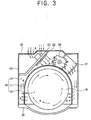
- a microwave oven 1 according to the preferred embodiment of the present invention comprises a main body 10 formed with a cooking compartment 12 and a component compartment 13 which are partitioned from each other by a partitioning wall 11; a door 30 mounted in front of the cooking compartment 12, opening and closing a front opening 12a, and including an operating panel 31; and an outer casing 40 installed outside the main body 10 and forming an outer appearance of the main body 10.
- the outer casing 40 comprises a front casing 41 enclosing a front side of the main body 10; a rear casing 42 enclosing a rear side of the main body 10; and a side-upper casing 43 enclosing the main body 10 in cooperation with the front casing 41 and the rear casing 42, and shaped like an inverted "U".
- a mounting bracket 50 of a plate shape mounted with kinds of components is provided between an upper part of the main body 10 and the side-upper casing 43.
- Air supplying holes 14 are formed on the partitioning wall 11 between the cooking compartment 12 and the component compartment 13, so that outside air A flows into the cooking compartment 12. Also, in the partitioning wall 11 are formed air discharging holes 15 corresponding to the air supplying holes 14 so as to discharge the air A supplied through the air supplying holes 14 with humidity in the cooking compartment 12 to the outside of the cooking compartment 12.
- the partitioning wall 11 partitions the cooking compartment 12 and the component compartment 13 in front and back sides thereof respectively, and is formed like a round shape so that the cooking compartment 12 is of a round shape. Accordingly, the air A from a fan 20 flows along a round shaped partitioning wall 11.
- heating components such as a HVT 17 transforming supplied voltage to high-voltage; a HVC (High Voltage Capacitor) 18 charging the high-voltage from the HVT 17; and a MGT 19 supplying microwaves into the cooking compartment 12 after generating the microwaves using the charged high-voltage of the HVC 18.
- the heating components 17, 18, and 19 are provided at a right rear side of the cooking compartment 12.
- the fan 20 cooling the heating components 17, 18, and 19 by blowing the air A is installed at a left rear side of the cooking compartment 12.
- An air inflow part 44 is formed at the rear casing 42 to flow the air A to the component compartment 13 by rotating of the fan 20.
- the air inflow part 44 is preferred but not necessary to be plural and be in a position to easily flow the air A into the component compartment 13 by the fan 20.
- the air inflow part 44 is provided at the rear casing 42 but it is possible that the air inflow part 44 is provided adjacent to the fan 20 at a left side of the side-upper casing 43.
- the fan 20 is mounted on a fan supporter 21.
- the fan supporter 21 and the fan 20 are inclined with respect to the cooking compartment 12. Accordingly, the air A flowing through the air inflow part 44 flows toward the heating components 17 and 19 in the component compartment 13 along the round shaped partitioning wall 11 by rotation of the fan 20, and then the air A cools the heating components 17 and 19. Accordingly, the conventional air guide guiding the air A toward the heating components 17 and 19 is not necessary.
- the air A which passed through the heating components 17 and 19, flows along the partitioning wall 11 again, and flows into the cooking compartment 12 through the air supplying holes 14 formed on a right side of the partitioning wall 11.
- the air A in the cooking compartment 12 circulates inside of the cooking compartment 12, the air A is discharged to an outside of the cooking compartment 12 through the air discharging holes 15 formed on the left side of the partitioning wall 11. Accordingly, the humidity inside of the cooking compartment 12 is eliminated therefrom.
- the air A discharged through the air discharging holes 15 on the partitioning wall 11 may be discharged to an outside of the microwave oven 1 through an air exhaust part 45 formed on the rear casing 42 after being guided toward an upper space 51 of the mounting bracket 50 (see Figure 2). Accordingly, the air A of high temperature and humidity in the cooking compartment 12 is easily discharged so that an inside of the door 30 is prevented from being humid.
- the heating components 17 and 19 in the component compartment 13 can be sufficiently cooled without a separate guide. Also, the air A which passed through the heating components 17 and 19, also flows along the partitioning wall 11 and flows into the cooking compartment 12 through the air supplying holes 14. Thereby eliminating the humidity in the cooking compartment 12.
Landscapes
- Physics & Mathematics (AREA)
- Electromagnetism (AREA)
- Engineering & Computer Science (AREA)
- Chemical & Material Sciences (AREA)
- Combustion & Propulsion (AREA)
- Mechanical Engineering (AREA)
- General Engineering & Computer Science (AREA)
- Electric Ovens (AREA)
- Constitution Of High-Frequency Heating (AREA)
Applications Claiming Priority (1)
| Application Number | Priority Date | Filing Date | Title |
|---|---|---|---|
| KR1020040045835A KR20050120474A (ko) | 2004-06-19 | 2004-06-19 | 전자렌지 |
Publications (2)
| Publication Number | Publication Date |
|---|---|
| EP1615471A2 true EP1615471A2 (de) | 2006-01-11 |
| EP1615471A3 EP1615471A3 (de) | 2006-01-18 |
Family
ID=35149572
Family Applications (1)
| Application Number | Title | Priority Date | Filing Date |
|---|---|---|---|
| EP05252777A Ceased EP1615471A3 (de) | 2004-06-19 | 2005-05-06 | Mikrowellenofen |
Country Status (4)
| Country | Link |
|---|---|
| US (1) | US7564011B2 (de) |
| EP (1) | EP1615471A3 (de) |
| JP (1) | JP3977383B2 (de) |
| KR (1) | KR20050120474A (de) |
Cited By (5)
| Publication number | Priority date | Publication date | Assignee | Title |
|---|---|---|---|---|
| WO2008026799A1 (en) | 2006-09-01 | 2008-03-06 | Lg Electronics, Inc. | Cooking apparatus |
| EP2066974A1 (de) * | 2006-09-12 | 2009-06-10 | LG Electronics Inc. | Kochvorrichtung |
| US7825358B2 (en) | 2006-09-01 | 2010-11-02 | Lg Electronics Inc. | Cooking apparatus having rear component space |
| US8143560B2 (en) | 2006-09-12 | 2012-03-27 | Lg Electronics Inc. | Cooking apparatus |
| US8168928B2 (en) | 2006-09-12 | 2012-05-01 | Lg Electronics Inc. | Cooking apparatus |
Families Citing this family (6)
| Publication number | Priority date | Publication date | Assignee | Title |
|---|---|---|---|---|
| KR101354327B1 (ko) * | 2007-10-11 | 2014-01-22 | 주식회사 동양매직 | Pcb 및 트랜스의 냉각 구조를 갖는 스팀 오븐 |
| JP5197236B2 (ja) * | 2008-08-28 | 2013-05-15 | 株式会社東芝 | 加熱調理器 |
| US8759727B2 (en) * | 2010-08-09 | 2014-06-24 | Coffee Technologies, International, Inc. | Microwave oven for roasting low moisture foods |
| KR20130027340A (ko) * | 2011-09-07 | 2013-03-15 | 삼성전자주식회사 | 전자레인지 |
| US9525490B2 (en) * | 2012-07-26 | 2016-12-20 | Aurrion, Inc. | Reconfigurable optical transmitter |
| CN107366933B (zh) * | 2017-07-21 | 2018-11-27 | 广东美的厨房电器制造有限公司 | 微波炉 |
Citations (4)
| Publication number | Priority date | Publication date | Assignee | Title |
|---|---|---|---|---|
| US20040016751A1 (en) * | 2002-07-26 | 2004-01-29 | Lg Electronics Inc. | Microwave oven |
| EP1389895A1 (de) * | 2002-08-15 | 2004-02-18 | Samsung Electronics Co., Ltd. | Mikrowellenofen |
| EP1435684A2 (de) * | 2003-01-03 | 2004-07-07 | Samsung Electronics Co., Ltd. | Lüftermotor und Mikrowellenofen mit einem solchen Motor |
| WO2005029922A1 (en) * | 2003-09-25 | 2005-03-31 | Lg Electronics Inc. | Microwave oven |
Family Cites Families (13)
| Publication number | Priority date | Publication date | Assignee | Title |
|---|---|---|---|---|
| JPS6032790U (ja) | 1983-08-10 | 1985-03-06 | 三洋電機株式会社 | 電子レンジ |
| JPH03140712A (ja) | 1989-10-26 | 1991-06-14 | Brother Ind Ltd | 電子レンジ |
| US5459301A (en) * | 1993-03-04 | 1995-10-17 | Miller; Alan E. | Cyclic microwave treatment of pressed garments |
| US5632921A (en) * | 1995-06-05 | 1997-05-27 | The Rubbright Group, Inc. | Cylindrical microwave heating applicator with only two modes |
| KR19980029624U (ko) | 1996-11-28 | 1998-08-17 | 배순훈 | 공기흐름을 개선한 전장실 냉각구조 |
| US6247246B1 (en) * | 1998-05-27 | 2001-06-19 | Denver Instrument Company | Microwave moisture analyzer: apparatus and method |
| KR20000005833U (ko) | 1998-09-03 | 2000-04-06 | 윤종용 | 전자레인지 |
| KR20020007453A (ko) | 2000-07-13 | 2002-01-29 | 윤종용 | 전자레인지 |
| US6624399B2 (en) * | 2000-11-15 | 2003-09-23 | Zenon Rypan | Space saving cooking appliance |
| JP2003172519A (ja) | 2001-12-04 | 2003-06-20 | Matsushita Electric Ind Co Ltd | 吊り下げ式高周波加熱装置 |
| US6911636B2 (en) * | 2002-01-03 | 2005-06-28 | Lg Electronics Inc. | Cooling fan for microwave oven |
| KR100442278B1 (ko) | 2002-07-26 | 2004-07-30 | 엘지전자 주식회사 | 전자 레인지의 방열 구조 |
| KR200337662Y1 (ko) | 2003-10-14 | 2004-01-03 | 주식회사 대우일렉트로닉스 | 전자렌지용 에어 가이드 |
-
2004
- 2004-06-19 KR KR1020040045835A patent/KR20050120474A/ko not_active Application Discontinuation
-
2005
- 2005-05-06 EP EP05252777A patent/EP1615471A3/de not_active Ceased
- 2005-06-13 JP JP2005172613A patent/JP3977383B2/ja not_active Expired - Fee Related
- 2005-06-20 US US11/155,586 patent/US7564011B2/en active Active
Patent Citations (4)
| Publication number | Priority date | Publication date | Assignee | Title |
|---|---|---|---|---|
| US20040016751A1 (en) * | 2002-07-26 | 2004-01-29 | Lg Electronics Inc. | Microwave oven |
| EP1389895A1 (de) * | 2002-08-15 | 2004-02-18 | Samsung Electronics Co., Ltd. | Mikrowellenofen |
| EP1435684A2 (de) * | 2003-01-03 | 2004-07-07 | Samsung Electronics Co., Ltd. | Lüftermotor und Mikrowellenofen mit einem solchen Motor |
| WO2005029922A1 (en) * | 2003-09-25 | 2005-03-31 | Lg Electronics Inc. | Microwave oven |
Cited By (17)
| Publication number | Priority date | Publication date | Assignee | Title |
|---|---|---|---|---|
| US7825358B2 (en) | 2006-09-01 | 2010-11-02 | Lg Electronics Inc. | Cooking apparatus having rear component space |
| EP2057417A1 (de) * | 2006-09-01 | 2009-05-13 | LG Electronics Inc. | Kochvorrichtung |
| US8941041B2 (en) | 2006-09-01 | 2015-01-27 | Lg Electronics Inc. | Cooking apparatus having a cooling system |
| EP2057417A4 (de) * | 2006-09-01 | 2009-08-19 | Lg Electronics Inc | Kochvorrichtung |
| WO2008026799A1 (en) | 2006-09-01 | 2008-03-06 | Lg Electronics, Inc. | Cooking apparatus |
| EP2237642A1 (de) * | 2006-09-01 | 2010-10-06 | Lg Electronics Inc. | Kochvorrichtung |
| US8304702B2 (en) | 2006-09-01 | 2012-11-06 | Lg Electronics Inc. | Cooking apparatus |
| US7910866B2 (en) | 2006-09-01 | 2011-03-22 | Lg Electronics Inc. | Cooking apparatus having multiple cooling flow paths |
| US8035065B2 (en) | 2006-09-01 | 2011-10-11 | Lg Electronics Inc. | Cooking apparatus having a door with a built in control panel |
| US8058594B2 (en) | 2006-09-01 | 2011-11-15 | Lg Electronics Inc. | Door for a cooking apparatus |
| US8680449B2 (en) | 2006-09-01 | 2014-03-25 | Lg Electronics Inc. | Cooking apparatus |
| US8164036B2 (en) | 2006-09-01 | 2012-04-24 | Lg Electronics Inc. | Cooking apparatus |
| US8586900B2 (en) | 2006-09-01 | 2013-11-19 | Lg Electronics Inc. | Cooking apparatus having cooling flow path |
| EP2066974A4 (de) * | 2006-09-12 | 2010-04-07 | Lg Electronics Inc | Kochvorrichtung |
| US8168928B2 (en) | 2006-09-12 | 2012-05-01 | Lg Electronics Inc. | Cooking apparatus |
| US8143560B2 (en) | 2006-09-12 | 2012-03-27 | Lg Electronics Inc. | Cooking apparatus |
| EP2066974A1 (de) * | 2006-09-12 | 2009-06-10 | LG Electronics Inc. | Kochvorrichtung |
Also Published As
| Publication number | Publication date |
|---|---|
| KR20050120474A (ko) | 2005-12-22 |
| US7564011B2 (en) | 2009-07-21 |
| EP1615471A3 (de) | 2006-01-18 |
| US20060000827A1 (en) | 2006-01-05 |
| JP2006003073A (ja) | 2006-01-05 |
| JP3977383B2 (ja) | 2007-09-19 |
Similar Documents
| Publication | Publication Date | Title |
|---|---|---|
| EP1615471A2 (de) | Mikrowellenofen | |
| EP0751698B1 (de) | Mikrowellenofen mit Umwalzheizung | |
| EP0767598A2 (de) | Konvektions- und Mikrowellenofen | |
| EP1439740B1 (de) | Wandmontierter Mikrowellenherd | |
| US5019682A (en) | Separable electrical cooker | |
| EP1731842A2 (de) | Ofen | |
| JP3668158B2 (ja) | フード兼用電子レンジの電装部品の冷却装置 | |
| US6972398B2 (en) | Wall mounted type microwave oven | |
| US20080156794A1 (en) | Microwave range having hood | |
| US7271373B2 (en) | Microwave oven | |
| EP2235445B1 (de) | Mikrowellenherd | |
| KR100402587B1 (ko) | 전자레인지의 공기유동시스템 | |
| EP1530406A1 (de) | Wandmontierter Mikrowellenofen | |
| KR20050030374A (ko) | 후드겸용 전자레인지 | |
| EP1680623B1 (de) | Mikrowellenofen und basisabdeckung dafür | |
| US6987254B2 (en) | Microwave oven | |
| US7332698B2 (en) | Microwave oven | |
| KR100595261B1 (ko) | 컨벡션형 전자레인지 | |
| KR101207306B1 (ko) | 컨벡션히팅유닛 및 이를 갖는 가열조리기 | |
| KR100286026B1 (ko) | 전자렌지 | |
| EP1680624B1 (de) | Mikrowellenofen und oberkanalkonstruktion dafür | |
| KR100582294B1 (ko) | 전자레인지의 전장실배기덕트어셈블리 | |
| KR100582293B1 (ko) | 전자레인지의 전장실배기덕트구조 | |
| KR980008922U (ko) | 전자레인지 | |
| KR20050030671A (ko) | 컨벡션형 전자 레인지 |
Legal Events
| Date | Code | Title | Description |
|---|---|---|---|
| PUAI | Public reference made under article 153(3) epc to a published international application that has entered the european phase |
Free format text: ORIGINAL CODE: 0009012 |
|
| PUAL | Search report despatched |
Free format text: ORIGINAL CODE: 0009013 |
|
| 17P | Request for examination filed |
Effective date: 20050518 |
|
| AK | Designated contracting states |
Kind code of ref document: A2 Designated state(s): AT BE BG CH CY CZ DE DK EE ES FI FR GB GR HU IE IS IT LI LT LU MC NL PL PT RO SE SI SK TR |
|
| AX | Request for extension of the european patent |
Extension state: AL BA HR LV MK YU |
|
| AK | Designated contracting states |
Kind code of ref document: A3 Designated state(s): AT BE BG CH CY CZ DE DK EE ES FI FR GB GR HU IE IS IT LI LT LU MC NL PL PT RO SE SI SK TR |
|
| AX | Request for extension of the european patent |
Extension state: AL BA HR LV MK YU |
|
| AKX | Designation fees paid |
Designated state(s): DE FR GB |
|
| 17Q | First examination report despatched |
Effective date: 20070524 |
|
| STAA | Information on the status of an ep patent application or granted ep patent |
Free format text: STATUS: THE APPLICATION HAS BEEN REFUSED |
|
| 18R | Application refused |
Effective date: 20081010 |