EP1615397B1 - Device to distribute the load using multiple criteria for a peripheral equipment of a label switched network - Google Patents
Device to distribute the load using multiple criteria for a peripheral equipment of a label switched network Download PDFInfo
- Publication number
- EP1615397B1 EP1615397B1 EP05102866A EP05102866A EP1615397B1 EP 1615397 B1 EP1615397 B1 EP 1615397B1 EP 05102866 A EP05102866 A EP 05102866A EP 05102866 A EP05102866 A EP 05102866A EP 1615397 B1 EP1615397 B1 EP 1615397B1
- Authority
- EP
- European Patent Office
- Prior art keywords
- paths
- processing means
- network
- ler
- switched
- Prior art date
- Legal status (The legal status is an assumption and is not a legal conclusion. Google has not performed a legal analysis and makes no representation as to the accuracy of the status listed.)
- Not-in-force
Links
Images

Classifications
-
- H—ELECTRICITY
- H04—ELECTRIC COMMUNICATION TECHNIQUE
- H04L—TRANSMISSION OF DIGITAL INFORMATION, e.g. TELEGRAPHIC COMMUNICATION
- H04L45/00—Routing or path finding of packets in data switching networks
-
- H—ELECTRICITY
- H04—ELECTRIC COMMUNICATION TECHNIQUE
- H04L—TRANSMISSION OF DIGITAL INFORMATION, e.g. TELEGRAPHIC COMMUNICATION
- H04L45/00—Routing or path finding of packets in data switching networks
- H04L45/24—Multipath
- H04L45/243—Multipath using M+N parallel active paths
-
- H—ELECTRICITY
- H04—ELECTRIC COMMUNICATION TECHNIQUE
- H04L—TRANSMISSION OF DIGITAL INFORMATION, e.g. TELEGRAPHIC COMMUNICATION
- H04L45/00—Routing or path finding of packets in data switching networks
- H04L45/52—Multiprotocol routers
Definitions
- the invention relates to the field of label switching networks, and more particularly the load distribution devices (or traffic) used in such networks.
- LSRs Label Switched Routers
- LSRs refer to two types of router or switch coupled together: Peripheral Routers (or LERs for "Label Edge Routers"), responsible for establishing a Label Switched Path (LSP) for each the data flows they receive when requested by the network manager, and core routers (LCRs), which are solely responsible for switching data flows and transmitting information data. network.
- Peripheral Routers or LERs for "Label Edge Routers”
- LSP Label Switched Path
- LCRs core routers
- the establishment of a switching path consists of adding to the data of a stream a tag associated with the path to follow and reserving the resources necessary for routing the stream, from the source node (LER) to the node of destination (LER), taking into account the type of service (or ToS for "Type of Service”) and / or the quality of service (or QoS for "Quality of Service”) that is (are) associated with it. flux.
- each stream In order for each source LER to establish a path, each stream must be associated with a source LER and a destination LER, with a transmission equivalence class (or FEC). for "Forwarding Equivalence Class") and a set of service data defining the type of service (or ToS) and / or the quality of service (or QoS).
- the calculation of an LSP switching path is made either from the determination of the shortest path between the start and destination nodes, or from the enumeration of a set of nodes that it must obligatorily include.
- a so-called signaling process establishes the switching path after having validated the steps taking into account constraints related to the QoS and / or ToS required for the flow.
- An LSP switching path can be seen as a sequence of links established between pairs of neighboring LSRs, starting at a source LER and terminating at a destination LER. Such a path is generally calculated using software for calculating LSPs switching paths, so as to support a traffic chosen according to criterion (s), such as the available bandwidth, the number of jumps (or links ), transfer time and administrative cost.
- s criterion
- congestion As known to those skilled in the art, a link that is shared by several LSP switching paths, borrowed by different traffic, can be overloaded, called congestion.
- load distribution devices or traffic have been proposed. They all aim to reduce the traffic on a congested link by distributing a portion of the traffic between alternative LSP switching paths having the same source LERs and destination LERs as the congested link, so as to ensure continuity of service.
- a first load balancing device called MPLS-OMP (for "MPLS Optimized Multi-Path"), is an adaptation of the OSPF-OMP device to MPLS networks, in which, on the one hand, the load information concerns all LSP switching paths and not links alone, and secondly, the establishment of an initial LSP switching path is based on a transfer time and the alternative LSP switching paths are generated by an SPF algorithm from the set of uncongested links. If only one alternative LSP switching path is generated, no load balancing is performed. Moreover, the generation of alternative LSP switching paths is done by relaxation of a single optimization criterion, such as the length of the path.
- this MPLS-OMP device allows the forced use of an LSP switching path that has not been selected by OSPF-OMP.
- This MPLS-OMP device has at least two disadvantages: the path selection is based on a single criterion, which is not optimal, and, although it rejects the paths with congested links, it does not select the paths of alternative LSP switching taking into consideration their respective loads.
- a second load distribution device called MATE (for "Multi-Path Adaptive Traffic Engineering"), implements an adaptive and distributed load distribution algorithm, designed to try to overcome the aforementioned drawbacks of the first device.
- MATE Multi-Path Adaptive Traffic Engineering
- This device is based on the assumption that several LSP switching paths are already available between a given source LER and destination LER.
- the congested links are detected using an active measurement mechanism of periodically transmitting probe packets between the source LER and the destination LER in both directions in order to have the transmission delay and the loss rate.
- the traffic is distributed between LSP switching paths by optimizing a scalar cost function under constraints representative of the total incoming traffic by the source and outgoing LER by the destination LER and the traffic rate using a given LSP switching path. Since the cost function takes into account transfer times and marginal loss rates, no synchronization and no direct measurement of traffic is required.
- This MATE device has at least three disadvantages: the use of probe packets in a dense MPLS network to detect congestion LSPs are assumed to have been previously computed based on a long-term criterion, so that their performance may not be the best possible when the device is triggered and may have links become congested in the meantime, and no traffic stabilization mechanism (in terms of progressive shifting) is planned.
- a load balancing device for a label switching communications network comprising a set of tag switching peripheral nodes (or LERs).
- the invention also relates to network peripheral equipment, such as a tag switching router, defining a peripheral node for a tag switched communications network and comprising a load balancing device of the type presented. above.
- the invention is particularly well suited to MPLS-type label switching communications networks (“MultiProtocol Label Switching") that processes asynchronous packet or data cell (GMPLS) flows (“Generalized MPLS”). which processes flows consisting not only of asynchronous data packets or cells but also synchronous frames or "light streams”.
- MPLS MPLS-type label switching communications networks
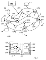
- FIG. 1 describes a non-limiting example of a label switched communications network (or "Label Switched Network”) comprising network equipment (LERn, LCRm) defining nodes and each provided with a load distribution device according to the invention.
- Label Switched Network or "Label Switched Network”
- IP MPLS Internet Protocol MultiProtocol Label Switching
- GMPLS IP Generalized MultiProtocol Label Switching
- An MPLS IP network generally comprises a multiplicity of label switching routers (or LSRs) linked together.
- LSRs label switching routers
- LER routers are responsible for establishing switching paths within the network while LCR routers are responsible for switching.
- link means a connection between two LSR routers
- path (or route) LSP a path between a source LER peripheral router and a destination LER peripheral router, defined by a sequence of links.
- node (or router) that follows another node within an LSP path is usually called “next hop” (or “next hop”). Therefore, the number of hops in an LSP path defines its length.
- An LSP path is typically calculated to optimize the transmission of traffic between a source LER peripheral router and a destination LER peripheral router.
- each peripheral router LER is arranged, when it constitutes a source (LER S ), so as to calculate the best LSP path for transferring the data streams it receives to the destination peripheral router LER ( LER D ), considering the service associated with the flows, the current topology of the network and the current loads of the links.
- the MPLS IP network generally includes a DB database in which the current topology of the network and the current loads of the links are stored.
- the peripheral routers LER are thus coupled to this database DB, which is preferably TE-LSA type (for "Traffic Engineering - Link State Advertisement"), and with which they communicate according to an extension link-state routing protocol. of type "TE” (or “Link State Routing Protocol - Traffic Engineering”) such as "OSPF-TE".
- the IP MPLS network also includes a network management system or NMS responsible for transmitting data to the LSR routers and extracting data from the latter in order to allow management of the network by an administrator (or manager).
- NMS network management system
- the LER destination router of an LSP path is the last router to which a tagged packet is transmitted within a zone (or domain), but not the destination address of said tagged packet.
- the terminals Ti are mobile stations, such as mobile phones (or cellular). But, it could be any type of communication terminal capable of exchanging data with other terminals or network equipment, such as for example fixed telephones, fax machines, personal digital assistants (or PDAs for "personal”). Digital Assistant "), desktop or portable computers, or content provider (or ASP) servers.
- the invention is intended to allow the distribution of load (or traffic) within a network with label switching (here IP MPLS type).
- the invention proposes for this purpose to implement, preferably in each peripheral router LERn of the network, a load distribution device (or traffic) D.
- This device D is not only responsible for calculating the best LSR paths for transmitting data streams received to a destination LER router, but also for resolving (or resorbing) the link congestion by means of a distribution mechanism. charge.
- the load distribution is triggered responsively in each source LER peripheral router that receives traffic and is momentarily connected to a destination peripheral router LER via at least one critical link. But, alternatively or in addition, it can also be triggered in preventive mode so to obey the instructions of the network administrator.
- the device D first comprises a first processing module PM1 responsible for determining equivalent tagged data flow switching paths (or LSP paths) between a source LER peripheral router and each destination LER peripheral router of the network (or domain) considered, taking into account a multiplicity of criteria associated with respective weights and a designation of critical links within the network.
- Each LSP equivalent path is issued with an associated cost value that allows its rank to be set relative to the other LSP equivalent paths delivered.
- This first PM1 processing module is preferably that which is known by the acronym MCLC (for "Multi-Criteria LSP Calculation"), which is described in particular in the patent document bearing the deposit number. FR 02 15966 and whose contents are included here by reference.
- MCLC Multi-Criteria LSP Calculation
- the first processing module PM1 is an MCLC module. The latter being fully described in the aforementioned patent document, it will not be described in detail below.
- an MCLC module simultaneously uses several criteria associated with relative weights (defining a cost vector), in order to determine the values of the links and to deliver LSP paths with equivalent performance (i.e. pareto-optimal) for each destination LER peripheral router of the network (or domain) considered.
- These delivered LSP paths can thus be classified according to a cost value based on the priority (or the relative weight) of each chosen criterion and the deviation from the highest value observed.
- the criteria used by such a MCLC module are preferably chosen from a group comprising at least the available bandwidth, the number of jumps, the transfer time and the administrative cost.
- the choice of criteria and their respective initial relative weight depends on the network administrator.
- Such an MCLC module is preferably interfaced to a OSPF-TE link state routing protocol.
- Each device D also comprises a second processing module PM2 coupled to the first processing module PM1 and responsible for the dynamic distribution of charge in reactive mode and / or in preventive mode.
- a second processing module PM2 coupled to the first processing module PM1 and responsible for the dynamic distribution of charge in reactive mode and / or in preventive mode.
- the device D operates both in reactive mode and in preventive mode.
- the second processing module PM2 is preferably interfaced to an OSPF-TE type link-state routing protocol.
- the second processing module PM2 of its device D firstly by selecting a set of K LSP paths equivalent and alternative to the initial LSP path, among the equivalent LSP paths that are delivered by the first processing module PM1.
- the first processing module PM1 delivers equivalent LSP paths starting from its source LER router and each terminating at one of the destination LER routers of the network (or domain) concerned.
- the second processing module PM2 determines an unequal distribution of the traffic to take the initial LSP path between the equivalent and alternative LSP paths P k of the game, according to their respective cost values M k .
- the device D can be triggered either in reactive mode or in preventive mode.
- the MPLS IP network administrator sends instructions to the relevant source LER router, via the NMS and the network, with the associated criteria and relative weights to be used by the first PM1 module, and the designation (or the identity) of one or more critical links, which can be represented by an administrative cost.
- the relevant source LER router via the NMS and the network, with the associated criteria and relative weights to be used by the first PM1 module, and the designation (or the identity) of one or more critical links, which can be represented by an administrative cost.
- other parameters specifying for example the date and / or time and / or the duration during which the device D must perform a dynamic load distribution can also be transmitted to the source LER router concerned. This preventive mode will be detailed later.
- the device D In the reactive mode, the device D is triggered when it receives the (or) designation (s) (or identity (s)) of one or more critical links whose congestion has been detected by a detection module DM1 when a verification (TE-LSA) of the contents of the DB database.
- a detection module DM1 can be either an external module connected to the source LER router, or a module internal to the device D, for example integrated in the first processing module PM1 as illustrated in FIG. 2.
- the optimal LSP path can be calculated either by the first PM1 processing module (MCLC module) in its standard operation, or by another LSP path calculation module that the first PM1 processing module.
- This other calculation module can be for example Dijkstra type. But, if the second PM2 processing module must intervene, the first PM1 processing module must be used.
- the detection module DM1 When the detection module DM1 detects congestion during a verification phase (TE-LSA), it triggers the first PM1 and second PM2 processing modules. More precisely, the first processing module PM1 comprises a management module MM coupled to the detection module DM1 and responsible for interrupting the timers controlling the computation of regular LSP paths in order to replace them with link charge counters, of elapsed time and load variation. Counters of this type are described, for example, in C. Villamizar's "OSPF Optimized Multipath (OSPF-OMP)", IETF draft, draft-ietf_ospf-omp-03, january 2002.
- OSPF-OMP OSPF Optimized Multipath
- the first processing module PM1 comprises an adaptation module AM coupled to the management module MM and responsible for determining a new weight for at least one of the criteria used in the absence of congestion. Since the main cause of congestion of a link is its overload, it is the weight W BW of the available bandwidth criterion that is preferentially modified, and more precisely increased (unless the network administrator does not refuse this option). The other (regular) criteria are retained (this is usually the theoretical transfer time, path length, load and / or administrative cost).
- the adaptation module AM After increasing the relative weight w BW of the available bandwidth criterion, using a predetermined formula, the adaptation module AM adjusts the respective weights w q (q ⁇ WB) of the other (regular) criteria so that that the sum total of all the relative weights is equal to 1 and that the predefined proportions between the weights w q are respected.
- w BW + (1 - w BW ) / R B , where w BW + is the updated weight and R B is a value greater than 1, and preferably greater than or equal to 2 by default, and representative of the relative weight increment ratio of the bandwidth criterion.
- a calculation module CM1 of the first processing module PM1 calculates all the equivalent LSP paths P k , which can respectively be established between its source LER router (LER S ) and each of the destination routers LER D of the network (or domain ) concerned, and the associated cost values M k , as described in the aforementioned patent document. It uses the criteria and their new relative weights provided by the AM adaptation module, as well as the information coming from the DB database (in particular those concerning the current topology of the network, the current loads of the links and congested links). The equivalent LSP paths P k can thus be classified according to their associated cost values M k .
- the best path LSP is for example referenced P 1 and associated with the cost value M 1 the best (M 1 ⁇ M 2 ... ⁇ M k , where M k is the worst value).
- the second processing module PM2 comprises a calculation module CM2 responsible for receiving the definitions of the K equivalent LSP paths P k , and the associated cost values M k , delivered by the first processing module PM1, in order to determine the dynamic distribution of charge.
- This dynamic load distribution first starts with a pre-selection among the K equivalent LSP paths P k of the equivalent LSP paths that have in common the destination LER router (LER D ), to which must be transmitted the received stream.
- This pre-selection provides K 'LSP paths equivalent and alternative to the LSP path initially provided and having at least one congested link.
- the initial LSP path passes through the source router LER1, the router LCR1, the router LCR5 and the destination router LER3, and the link between the routers LCR1 and LCR5 is congested.
- the dynamic load distribution is continued by selecting, from among the K 'preselected LSP paths, a set of L paths LSP equivalent P I and alternative to the initial path LSP congested.
- the path LSP P 1 goes through the source router LER1, the router LCR1, the router LCR4, the router LCR5 and the destination router LER3
- the path LSP P 2 goes through the source router LER1, the router LCR1, the LCR3 router, the LCR6 router and the destination router LER3
- the LSP path P 3 passes through the source router LER1, the router LCR2, the router LCR3, the router LCR5 and the destination router LER3.
- the calculation module CM2 determines the proportion Q I of the traffic that can be assigned to each selected LSP path P I , given its cost value M I.
- the calculation module CM2 feeds, in traffic allocation proportions Q l and multicore coefficients C l, a distribution module DM2 that comprises the second processing module PM2.
- the DM2 distribution module located in the source LER router, is responsible for distributing the data packets of the received traffic flows and to be transferred to the destination LER router concerned.
- FEC transmission forward equivalence classes
- a stream is identified by an FEC, which drives all the data of this stream on the same single LSP path.
- the association of a stream to be switched to an FEC is performed by the source LER router.
- the FEC I corresponds to the selected LSP P I path, which must carry IQ% of the received stream, to be transferred.
- the distribution module DM2 then preferably performs a dynamic hashing so as to unequally distribute (or distribute) the data streams received by its source LER router, as illustrated in FIG. 3.
- the distribution of traffic in MPLS is naturally of type "flow” (or “flow-based”).
- flow interrupts can be minimized by using a dynamic flow identifier hashing scheme.
- the data streams are represented by bytes including the protocol identifier, the source and destination MPLS ports, and the source and destination IP addresses, as well as other characteristics, for example related to quality of service (QoS).
- QoS quality of service
- the assignment of the data streams can proceed as follows.
- the acronyms LS1 to LS3 denote the three outgoing links used. This is only an illustrative example, since the number of outgoing links may indeed be less than or equal to the number of FECs j .
- This assignment represents the objective that the DM2 distribution module must reach in a given time interval and by means of an incremental data flow offset of the initial LSP path (including the critical link) to the different selected LSP P I paths. .
- the distribution module DM2 preferentially interrupts the data flow offset to a selected LSP path P I when the target proportion of the traffic Q which has been affected is reached.
- the distribution module DM2 preferably shifts the traffic progressively from one selected LSP path to the other according to a chosen shift rate (or "pace shifting") and / or a chosen shift speed.
- the offset rate can be finely tuned by means of mechanisms of the type used in the OSPF-OMP algorithm (for example defining the elementary quantity of flows to be shifted at the same time and the number of quantities and rules for decide when the offset rhythm should be adjusted).
- the distribution module DM2 may be arranged to implement a stabilization mechanism (or hysteresis thresholding) for distributing the allocated flow to a selected LSP path when its load exceeds a chosen threshold (for example equal to 50%), and to interrupt this distribution when its load is less than or equal to said threshold minus another chosen threshold (for example equal to 30%).
- a stabilization mechanism or hysteresis thresholding
- the second PM2 processing module preferentially updates the database DB and the routing table which is stored in a dedicated memory of its source LER router.
- a first difference comes from the triggering mode of the management module MM of the first processing module PM1. This is indeed triggered when it receives instructions from the administrator of the IP MPLS network, as indicated above.
- the MM management module interrupts the timers that control the computation of regular LSP paths, as in the reactive mode.
- the adaptation module AM increases (or modifies) the weight of at least one of the criteria used in the absence of congestion (for example the weight W BW of the available bandwidth criterion), in accordance with the instructions received from the network administrator.
- the AM adaptation module then adjusts the respective weights w q (q ⁇ WB) of the other criteria (regular), as in the reactive mode.
- the adaptation module AM then queries the database DB in order to obtain the information relating to the topology of the current network and the current loads of the links. It then provides all this information to the CM1 calculation module as well as the associated criteria and relative weights to use.
- the calculation performed by the calculation module CM1 is then identical to that described above with reference to the reactive mode. Furthermore, the load distribution performed by the second processing module is almost identical to that described above with reference to the reactive mode. The difference may indeed come from the fact that the calculation module CM2 may be compelled to calculate the rate and / or the offset speed according to the instructions received from the administrator of the IP MPLS network.
- the charge distribution devices D can be implemented in the form of electronic circuits, software (or computer) modules, or a combination of circuits and software.
- the invention provides distributed load balancing devices in each LER peripheral router, thereby enabling dynamic and fast congestions processing.
- the invention is suitable both for long-term congestions (of the order of the hour) and short-term congestions (of the order of one minute).
- the alternative LSP paths are calculated when the device is triggered, so they are determined based on updated network information, which ensures the exclusion of LSP paths with congested links.
- the invention makes it possible to increase the robustness and stability because the traffic distribution remains unchanged throughout each alternative LSP path.
Abstract
Description
L'invention concerne le domaine des réseaux à commutation d'étiquettes, et plus particulièrement les dispositifs de répartition de charge (ou trafic) utilisés dans de tels réseaux.The invention relates to the field of label switching networks, and more particularly the load distribution devices (or traffic) used in such networks.
Comme de nombreux réseaux de communications, un réseau dit « à commutation d'étiquettes » (ou « label switched network »), par exemple de type MPLS ou GMPLS, peut être schématiquement résumé à une multiplicité d'équipements de commutation raccordés les uns aux autres et constituant des noeuds destinés à router des paquets de données, ou plus généralement des flux de données, entre des terminaux de communication ou des serveurs qui leurs sont couplés. Dans un réseau à commutation d'étiquettes, les équipements de commutation sont appelés routeurs de commutation d'étiquettes (ou LSRs pour « Label Switched Routers »).Like many communications networks, a so-called "label switched network", for example of the MPLS or GMPLS type, can be schematically summarized to a multiplicity of switching equipment connected to each other. others and constituting nodes for routing data packets, or more generally data streams, between communication terminals or servers coupled thereto. In a switched label network, switching equipment is called Label Switched Routers (LSRs).
Les LSRs désignent deux types de routeur ou commutateur couplés entre eux : les routeurs périphériques (ou LERs pour « Label Edge Routers »), chargés d'établir un chemin de commutation d'étiquettes (ou LSP pour « Label Switched Path ») pour chaque flux de données qu'ils reçoivent lorsque le gestionnaire du réseau le leur demande, et les routeurs de coeur (ou LCRs pour « Label Core Routers »), uniquement chargés de la commutation des flux de données et de la transmission des données d'information du réseau.LSRs refer to two types of router or switch coupled together: Peripheral Routers (or LERs for "Label Edge Routers"), responsible for establishing a Label Switched Path (LSP) for each the data flows they receive when requested by the network manager, and core routers (LCRs), which are solely responsible for switching data flows and transmitting information data. network.
L'établissement d'un chemin de commutation consiste à adjoindre aux données d'un flux une étiquette associée au chemin à suivre et à réserver les ressources nécessaires à l'acheminement du flux, depuis le noeud source (LER) jusqu'au noeud de destination (LER), compte tenu du type de service (ou ToS pour « Type of Service ») et/ou de la qualité de service (ou QoS pour « Quality of Service ») qui est (sont) associé(s) à ce flux. Afin que chaque LER source puisse établir un chemin, chaque flux doit être associé à un LER source et un LER de destination, à une classe d'équivalence de transmission (ou FEC pour « Forwarding Equivalence Class ») et à un ensemble de données de service définissant le type de service (ou ToS) et/ou la qualité de service (ou QoS).The establishment of a switching path consists of adding to the data of a stream a tag associated with the path to follow and reserving the resources necessary for routing the stream, from the source node (LER) to the node of destination (LER), taking into account the type of service (or ToS for "Type of Service") and / or the quality of service (or QoS for "Quality of Service") that is (are) associated with it. flux. In order for each source LER to establish a path, each stream must be associated with a source LER and a destination LER, with a transmission equivalence class (or FEC). for "Forwarding Equivalence Class") and a set of service data defining the type of service (or ToS) and / or the quality of service (or QoS).
Le calcul d'un chemin de commutation LSP s'effectue soit à partir de la détermination du chemin le plus court entre les noeuds de départ et de destination, soit à partir de l'énumération d'un ensemble de noeuds qu'il doit obligatoirement comporter.The calculation of an LSP switching path is made either from the determination of the shortest path between the start and destination nodes, or from the enumeration of a set of nodes that it must obligatorily include.
A partir de la liste des noeuds produite par le calcul, un processus dit de signalisation établit le chemin de commutation après en avoir validé les étapes compte tenu de contraintes liées à la QoS et/ou ToS requise pour le flux.From the list of nodes produced by the calculation, a so-called signaling process establishes the switching path after having validated the steps taking into account constraints related to the QoS and / or ToS required for the flow.
Un chemin de commutation LSP peut être vu comme une séquence de liens établis entre des couples de LSRs voisins, commençant au niveau d'un LER source et se terminant au niveau d'un LER de destination. Un tel chemin est généralement calculé au moyen d'un logiciel de calcul de chemins de commutation LSPs, de manière à supporter un trafic choisi en fonction de critère(s), tels que la bande passante disponible, le nombre de sauts (ou de liens), le temps de transfert et le coût administratif.An LSP switching path can be seen as a sequence of links established between pairs of neighboring LSRs, starting at a source LER and terminating at a destination LER. Such a path is generally calculated using software for calculating LSPs switching paths, so as to support a traffic chosen according to criterion (s), such as the available bandwidth, the number of jumps (or links ), transfer time and administrative cost.
Comme le sait l'homme de l'art, un lien qui est partagé par plusieurs chemins de commutation LSP, empruntés par des trafics différents, peut faire l'objet d'une surcharge, appelée congestion.As known to those skilled in the art, a link that is shared by several LSP switching paths, borrowed by different traffic, can be overloaded, called congestion.
Afin de résorber ces congestions de lien, des dispositifs de répartition de charge (ou trafic) ont été proposés. Ils ont tous pour objectif de réduire le trafic sur un lien congestionné en répartissant une partie du trafic entre des chemins de commutation LSP alternatifs ayant les mêmes LER source et LER de destination que le lien congestionné, de manière à assurer une continuité de service.In order to reduce these link congestion, load distribution devices (or traffic) have been proposed. They all aim to reduce the traffic on a congested link by distributing a portion of the traffic between alternative LSP switching paths having the same source LERs and destination LERs as the congested link, so as to ensure continuity of service.
Un premier dispositif de répartition de charge, appelé MPLS-OMP (pour « MPLS Optimized Multi-Path »), est une adaptation du dispositif OSPF-OMP aux réseaux MPLS, dans laquelle, d'une part, l'information de charge concerne tous les chemins de commutation LSP et non des liens seuls, et d'autre part, l'établissement d'un chemin de commutation LSP initial est basé sur un temps de transfert et les chemins de commutation LSP alternatifs sont générés par un algorithme de type SPF à partir de l'ensemble des liens non congestionnés. Si un seul chemin de commutation LSP alternatif est généré, aucune répartition de trafic (ou « load balancing ») n'est effectuée. Par ailleurs, la génération de chemins de commutation LSP alternatifs se fait par relaxation d'un unique critère d'optimisation, tel que la longueur du chemin. Plus précisément, tous les chemins de commutation LSP correspondant à un écart inférieur ou égal à deux, par rapport à l'unique critère, sont retenus. En outre, ce dispositif MPLS-OMP permet l'utilisation forcée d'un chemin de commutation LSP qui n'a pas été sélectionné par OSPF-OMP.A first load balancing device, called MPLS-OMP (for "MPLS Optimized Multi-Path"), is an adaptation of the OSPF-OMP device to MPLS networks, in which, on the one hand, the load information concerns all LSP switching paths and not links alone, and secondly, the establishment of an initial LSP switching path is based on a transfer time and the alternative LSP switching paths are generated by an SPF algorithm from the set of uncongested links. If only one alternative LSP switching path is generated, no load balancing is performed. Moreover, the generation of alternative LSP switching paths is done by relaxation of a single optimization criterion, such as the length of the path. More precisely, all the LSP switching paths corresponding to a difference of less than or equal to two, with respect to the single criterion, are retained. In addition, this MPLS-OMP device allows the forced use of an LSP switching path that has not been selected by OSPF-OMP.
Ce dispositif MPLS-OMP présente au moins deux inconvénients : la sélection de chemin repose sur un unique critère, ce qui n'est pas optimal, et, bien qu'il rejette les chemins comportant des liens congestionnés, il ne sélectionne pas les chemins de commutation LSP alternatifs en prenant en considération leurs charges respectives.This MPLS-OMP device has at least two disadvantages: the path selection is based on a single criterion, which is not optimal, and, although it rejects the paths with congested links, it does not select the paths of alternative LSP switching taking into consideration their respective loads.
Un second dispositif de répartition de charge, appelé MATE (pour « Multi-Path Adaptative Traffic Engineering »), met en oeuvre un algorithme de répartition de charge adaptatif et distribué, conçu pour tenter de remédier aux inconvénients précités du premier dispositif. Ce dispositif repose sur l'hypothèse que plusieurs chemins de commutation LSP sont déjà disponibles entre un LER source et un LER de destination donnés. Les liens congestionnés sont détectés au moyen d'un mécanisme de mesure actif consistant à transmettre périodiquement dans les deux sens des paquets sonde entre le LER source et le LER de destination afin de disposer du délai de transmission et du taux de perte. Le trafic est réparti entre des chemins de commutation LSP en optimisant une fonction de coût scalaire sous des contraintes représentatives du trafic total entrant par le LER source et sortant par le LER de destination et du débit de trafic en utilisant un chemin de commutation LSP donné. La fonction de coût prenant en considération des temps de transfert et des taux de perte marginaux, aucune synchronisation et aucune mesure directe de trafic ne sont nécessaires.A second load distribution device, called MATE (for "Multi-Path Adaptive Traffic Engineering"), implements an adaptive and distributed load distribution algorithm, designed to try to overcome the aforementioned drawbacks of the first device. This device is based on the assumption that several LSP switching paths are already available between a given source LER and destination LER. The congested links are detected using an active measurement mechanism of periodically transmitting probe packets between the source LER and the destination LER in both directions in order to have the transmission delay and the loss rate. The traffic is distributed between LSP switching paths by optimizing a scalar cost function under constraints representative of the total incoming traffic by the source and outgoing LER by the destination LER and the traffic rate using a given LSP switching path. Since the cost function takes into account transfer times and marginal loss rates, no synchronization and no direct measurement of traffic is required.
Ce dispositif MATE présente au moins trois inconvénients : l'utilisation de paquets sonde dans un réseau MPLS dense pour détecter les congestions LSP sont supposés avoir été calculés antérieurement compte tenu d'un critère à long terme, si bien que leurs performances ne sont pas forcément les meilleures possible lorsque le dispositif est déclenché et qu'ils peuvent comporter des liens devenus congestionnés dans l'intervalle, et aucun mécanisme de stabilisation de trafic (en terme de décalage progressif) n'est prévu.This MATE device has at least three disadvantages: the use of probe packets in a dense MPLS network to detect congestion LSPs are assumed to have been previously computed based on a long-term criterion, so that their performance may not be the best possible when the device is triggered and may have links become congested in the meantime, and no traffic stabilization mechanism (in terms of progressive shifting) is planned.
Aucun dispositif connu n'étant entièrement satisfaisant, l'invention a donc pour but d'améliorer la situation.Since no known device is entirely satisfactory, the object of the invention is therefore to improve the situation.
Elle propose à cet effet un dispositif de répartition de charge, pour un réseau de communications à commutation d'étiquettes comportant un ensemble de noeuds périphériques de commutation d'étiquettes (ou LER).To this end, it proposes a load balancing device for a label switching communications network comprising a set of tag switching peripheral nodes (or LERs).
Ce dispositif se caractérise par le fait qu'il comporte :
- des premiers moyens de traitement chargés de déterminer des chemins équivalents de commutation de flux de données étiquetés (ou LSP) entre un noeud périphérique source et chaque noeud périphérique de destination de l'ensemble, compte tenu d'une multiplicité de critères associés à des poids respectifs et d'une désignation des liens critiques au sein du réseau, les chemins de commutation équivalents étant classés en fonction de valeurs de coût associées, et
- des seconds moyens de traitement chargés de sélectionner parmi les chemins de commutation équivalents déterminés par les premiers moyens de traitement, un jeu de chemins de commutation équivalents et alternatifs à un chemin de commutation initial, établi entre un noeud périphérique source et un noeud périphérique de destination et comportant un lien critique, puis de déterminer une répartition entre les chemins de commutation équivalents et alternatifs de ce jeu, en fonction de leurs valeurs de coût respectives, d'un trafic devant emprunter ledit chemin de commutation initial.
- first processing means for determining equivalent labeled data stream switching (or LSP) paths between a source peripheral node and each destination peripheral node of the set, taking into account a multiplicity of criteria associated with weights respective links and a designation of the critical links within the network, the equivalent switching paths being ranked according to associated cost values, and
- second processing means responsible for selecting from among the equivalent switching paths determined by the first processing means a set of switching paths that are equivalent and alternative to an initial switching path, established between a source peripheral node and a destination peripheral node and having a critical link, then determining a distribution between the equivalent and alternative switching paths of this game, based on their respective cost values, of a traffic to take said initial switching path.
Le dispositif selon l'invention peut comporter d'autres caractéristiques complémentaires qui peuvent être prises séparément et/ou en combinaison, et notamment :
- les critères utilisés par les premiers moyens de traitement peuvent être la bande passante disponible, le nombre de sauts, le temps de transfert et/ou bande passante disponible, le nombre de sauts, le temps de transfert et/ou le coût administratif,
- ses premiers moyens de traitement peuvent être agencés de manière à fonctionner en mode préventif. Dans ce cas, ils déterminent les chemins de commutation équivalents lorsqu'ils reçoivent des instructions du réseau comportant les critères et leurs poids respectifs ainsi que les désignations de lien(s) critique(s) (éventuellement sous la forme de leurs coûts administratifs). Un lien critique peut alors être soit un lien congestionné, soit un lien que le gestionnaire du réseau veut éviter d'utiliser,
- ses premiers moyens de traitement peuvent être agencés de manière à fonctionner en mode réactif. Dans ce cas, ils déterminent les chemins de commutation équivalents lorsqu'ils reçoivent des informations désignant au moins un lien critique congestionné au sein du réseau. Ces informations peuvent par exemple provenir de moyens de détection du dispositif chargés de détecter les liens critiques congestionnés. Par ailleurs, les premiers moyens de traitement sont de préférence agencés de manière à déterminer les chemins de commutation équivalents après avoir modifiés les poids associés aux critères. Pour ce faire, les premiers moyens de traitement peuvent par exemple augmenter le poids qui est associé au critère de bande passante, puis ajuster les poids des autres critères en fonction de cette augmentation, de sorte que la somme des poids des critères utilisés soit égale à 1 et que les proportions entre les poids soient respectées,
- ses premiers moyens de traitement déterminent préférentiellement les chemins de commutation équivalents à partir de valeurs mises à jour des bandes passantes des liens et de la topologie en cours du réseau, en particulier dans le mode de fonctionnement préventif,
- ses seconds moyens de traitement peuvent être agencés de manière à, d'une part, soumettre à une fonction de hachage dynamique les flux de données, reçus par le noeud périphérique source et définis par des paramètres de source réseau, de destination réseau, de port source et de port de destination, afin de délivrer un nombre choisi de cases (ou « bins ») de valeurs, et d'autre part, affecter les cases de valeurs, représentatives des flux de données reçus, aux chemins de commutation équivalents et alternatifs du jeu en fonction de leurs valeurs de coût respectives. Dans ce cas, les seconds moyens de traitement peuvent être chargés d'affecter les flux de données reçus, pendant un intervalle de temps choisi et selon un décalage de flux incrémental, à chacun des chemins de commutation équivalents et alternatifs du jeu, le décalage de flux sur l'un des chemins étant interrompu lorsque la répartition de trafic associée, fonction de sa valeur de coût, est atteinte. Les seconds moyens de traitement procèdent alors préférentiellement au décalage de flux de façon progressive en fonction d'un rythme de décalage (ou « pace shifting ») choisi et/ou d'une vitesse de décalage choisie,
- ses seconds moyens de traitement peuvent être chargés de mettre à jour la table de routage d'un noeud périphérique source après avoir déterminé les chemins de commutation équivalents et alternatifs du jeu et la répartition de trafic,
- ses premiers et seconds moyens de traitement sont préférentiellement interfacés à un protocole de routage à état de lien à extension de type « TE », et en particulier de type « OSPF-TE ».
- the criteria used by the first processing means can be the available bandwidth, the number of jumps, the transfer time and / or available bandwidth, number of hops, transfer time and / or administrative cost,
- its first processing means can be arranged to operate in a preventive mode. In this case, they determine the equivalent switching paths when they receive instructions from the network including the criteria and their respective weights as well as the critical link designations (possibly in the form of their administrative costs). A critical link can then be either a congested link or a link that the network manager wants to avoid using,
- its first processing means can be arranged to operate in a reactive mode. In this case, they determine the equivalent switching paths when they receive information designating at least one congested critical link within the network. This information may for example come from device detection means for detecting congested critical links. On the other hand, the first processing means are preferably arranged so as to determine the equivalent switching paths after having modified the weights associated with the criteria. To do this, the first processing means can for example increase the weight that is associated with the bandwidth criterion, and then adjust the weights of the other criteria according to this increase, so that the sum of the weights of the criteria used is equal to 1 and that the proportions between the weights are respected,
- its first processing means preferentially determine the equivalent switching paths from updated values of the bandwidths of the links and the current topology of the network, in particular in the preventive operation mode,
- its second processing means may be arranged to, on the one hand, submit to a dynamic hash function the data streams, received by the source node and defined by network source settings, network destination, port source and destination port, in order to deliver a selected number of boxes (or "bins") of values, and secondly, to assign the value boxes, representative of the received data streams, to the alternate and equivalent switching paths of the game based on their respective cost values. In this case, the second processing means may be responsible for assigning the received data streams, during a selected time interval and in an incremental flux offset, to each of the equivalent and alternative switching paths of the set, the offset of flow on one of the paths being interrupted when the associated traffic distribution, depending on its cost value, is reached. The second processing means then proceed preferentially to the flux offset in a progressive manner as a function of a chosen shift rate (or "shifting rate") and / or of a chosen shift speed,
- its second processing means may be responsible for updating the routing table of a source peripheral node after determining the equivalent and alternative switching paths of the game and the traffic distribution,
- its first and second processing means are preferably interfaced to an extension-type link-type routing protocol of "TE" type, and in particular of "OSPF-TE" type.
L'invention porte également sur un équipement périphérique de réseau, tel qu'un routeur de commutation d'étiquettes, définissant un noeud périphérique pour un réseau de communications à commutation d'étiquettes et comprenant un dispositif de répartition de charge du type de celui présenté ci-avant.The invention also relates to network peripheral equipment, such as a tag switching router, defining a peripheral node for a tag switched communications network and comprising a load balancing device of the type presented. above.
Par ailleurs, l'invention est particulièrement bien adaptée aux réseaux de communications à commutation d'étiquettes de type MPLS (« MultiProtocol Label Switching ») qui traite des flux constitués de paquets ou cellules de données asynchrones, ou GMPLS (« Generalized MPLS ») qui traite des flux constitués non seulement de paquets ou cellules de données asynchrones mais également de trames (ou « frames ») synchrones ou de flux de lumière (ou « light streams »).Furthermore, the invention is particularly well suited to MPLS-type label switching communications networks ("MultiProtocol Label Switching") that processes asynchronous packet or data cell (GMPLS) flows ("Generalized MPLS"). which processes flows consisting not only of asynchronous data packets or cells but also synchronous frames or "light streams".
D'autres caractéristiques et avantages de l'invention apparaîtront à l'examen de la description détaillée ci-après, et des dessins annexés, sur lesquels :
- la figure 1 illustre de façon schématique un exemple de réseau de communications à commutation d'étiquettes comportant une multiplicité de routeurs (ou noeuds) périphériques (LERs), équipés d'un dispositif de répartition de charge selon l'invention, et couplés entre eux par des routeurs (ou noeuds) de coeur (LCRs),
- la figure 2 illustre de façon schématique un exemple de réalisation d'un dispositif de répartition de charge selon l'invention, et
- la figure 3 illustre de façon schématique un exemple de décalage de trafic incrémental au moyen d'une fonction de hachage, dans le cas d'une répartition de trafic entre trois chemins LSP alternatifs.
- FIG. 1 schematically illustrates an example of a tag switched communications network comprising a multiplicity of peripheral routers (or nodes) (LERs), equipped with a load distribution device according to the invention, and coupled together. by routers (or nodes) of heart (LCRs),
- FIG. 2 schematically illustrates an exemplary embodiment of a load distribution device according to the invention, and
- FIG. 3 schematically illustrates an example of incremental traffic shift by means of a hash function, in the case of a traffic distribution between three alternative LSP paths.
Les dessins annexés pourront non seulement servir à compléter l'invention, mais aussi contribuer à sa définition, le cas échéant.The attached drawings may not only serve to complete the invention, but also contribute to its definition, if any.
On se réfère tout d'abord à la figure 1 pour décrire un exemple non limitatif de réseau de communications à commutation d'étiquettes (ou « Label Switched Network ») comportant des équipements de réseau (LERn, LCRm) définissant des noeuds et pourvus chacun d'un dispositif de répartition de charge selon l'invention.Reference is first made to FIG. 1 to describe a non-limiting example of a label switched communications network (or "Label Switched Network") comprising network equipment (LERn, LCRm) defining nodes and each provided with a load distribution device according to the invention.
Dans ce qui suit, on considère que le réseau est de type IP MPLS (« Internet Protocol MultiProtocol Label Switching »). Mais bien entendu, l'invention n'est pas limitée à ce seul type de réseau à commutation d'étiquettes. Elle concerne d'une manière générale tous les types de réseau à commutation d'étiquettes, comme par exemple les réseaux de type IP GMPLS (« IP Generalized MultiProtocol Label Switching »).In what follows, we consider that the network is IP MPLS ("Internet Protocol MultiProtocol Label Switching"). But of course, the invention is not limited to this single type of label switching network. It generally relates to all types of label switched network, such as IP type networks GMPLS ("IP Generalized MultiProtocol Label Switching").
Un réseau IP MPLS comporte généralement, une multiplicité de routeurs (ou noeuds) de commutation d'étiquettes (ou LSRs pour « Label Switched Routers ») couplés entre eux. Ces LSRs peuvent être regroupés en deux catégories : les routeurs périphériques (ou LERs pour « Label Edge Routers ») LERn (ici n = 1 à 5), et les routeurs de coeur (ou LCRs pour « Label Core Routers ») LCRm (ici m = 1 à 6). Comme on le verra plus loin, les routeurs LER sont chargés d'établir des chemins de commutation au sein du réseau tandis que les routeurs LCR sont chargés de la commutation.An MPLS IP network generally comprises a multiplicity of label switching routers (or LSRs) linked together. These LSRs can be grouped into two categories: the peripheral routers (or LERs for "Label Edge Routers") LERn (here n = 1 to 5), and the core routers (or LCRs for "Label Core Routers") LCRm (here m = 1 to 6). As will be seen later, LER routers are responsible for establishing switching paths within the network while LCR routers are responsible for switching.
Par ailleurs, dans ce qui suit on entend par « lien » une connexion entre deux routeurs LSR, et par « chemin (ou route) LSP » un trajet entre un routeur périphérique LER source et un routeur périphérique LER de destination, défini par une séquence de liens. En outre, le noeud (ou routeur) qui suit un autre noeud au sein d'un chemin LSP est généralement appelé « saut suivant » (ou « next hop »). Par conséquent, le nombre de sauts d'un chemin LSP définit sa longueur.Furthermore, in the following terms "link" means a connection between two LSR routers, and "path (or route) LSP" a path between a source LER peripheral router and a destination LER peripheral router, defined by a sequence of links. In addition, the node (or router) that follows another node within an LSP path is usually called "next hop" (or "next hop"). Therefore, the number of hops in an LSP path defines its length.
Un chemin LSP est généralement calculé de manière à optimiser la transmission de trafic entre un routeur périphérique LER source et un routeur périphérique LER de destination. Dans un réseau IP MPLS, chaque routeur périphérique LER est agencé, lorsqu'il constitue une source (LERS), de manière à calculer le meilleur chemin LSP pour transférer les flux de données qu'il reçoit vers le routeur périphérique LER de destination (LERD), compte tenu du service associé aux flux, de la topologie en cours du réseau et des charges en cours des liens.An LSP path is typically calculated to optimize the transmission of traffic between a source LER peripheral router and a destination LER peripheral router. In an IP MPLS network, each peripheral router LER is arranged, when it constitutes a source (LER S ), so as to calculate the best LSP path for transferring the data streams it receives to the destination peripheral router LER ( LER D ), considering the service associated with the flows, the current topology of the network and the current loads of the links.
Le réseau IP MPLS comporte généralement une base de données DB dans laquelle sont notamment stockées la topologie en cours du réseau et les charges en cours des liens. Les routeurs périphériques LER sont donc couplés à cette base de données DB, qui est préférentiellement de type TE-LSA (pour "Trafic Engineering - Link State Advertisement"), et avec laquelle ils communiquent selon un protocole de routage à état de lien à extension de type « TE » (ou « link state routing protocol - Traffic Engineering ») tel que « OSPF-TE ».The MPLS IP network generally includes a DB database in which the current topology of the network and the current loads of the links are stored. The peripheral routers LER are thus coupled to this database DB, which is preferably TE-LSA type (for "Traffic Engineering - Link State Advertisement"), and with which they communicate according to an extension link-state routing protocol. of type "TE" (or "Link State Routing Protocol - Traffic Engineering") such as "OSPF-TE".
Le réseau IP MPLS comporte également un système de gestion de réseau ou NMS chargé de transmettre des données aux routeurs LSR et d'extraire des données de ces derniers afin de permettre la gestion du réseau par un administrateur (ou gestionnaire).The IP MPLS network also includes a network management system or NMS responsible for transmitting data to the LSR routers and extracting data from the latter in order to allow management of the network by an administrator (or manager).
Il est important de noter que le routeur périphérique LER de destination d'un chemin LSP est le dernier routeur auquel est transmis un paquet étiqueté au sein d'une zone (ou domaine), mais pas l'adresse de destination dudit paquet étiqueté.It is important to note that the LER destination router of an LSP path is the last router to which a tagged packet is transmitted within a zone (or domain), but not the destination address of said tagged packet.
Une multiplicité de terminaux d'utilisateurs ou d'entreprises Ti (ici i = 1 à 5) sont susceptibles de se raccorder à certains au moins des LERs afin de pouvoir échanger des données entre eux.A multiplicity of user terminals or Ti companies (here i = 1 to 5) are likely to connect to at least some of the LERs in order to be able to exchange data with each other.
Dans ce qui suit on considère que les terminaux Ti sont des stations mobiles, telles que des téléphones mobiles (ou cellulaires). Mais, il pourrait s'agir de tout type de terminal de communications capable d'échanger des données avec d'autres terminaux ou équipements de réseau, comme par exemple des téléphones fixes, des télécopieurs, des assistants numériques personnels (ou PDA pour « Personal Digital Assistant »), des ordinateurs fixes ou portables ou des serveurs de fournisseurs de contenus (ou ASP pour « Application Service Provider »).In the following it is considered that the terminals Ti are mobile stations, such as mobile phones (or cellular). But, it could be any type of communication terminal capable of exchanging data with other terminals or network equipment, such as for example fixed telephones, fax machines, personal digital assistants (or PDAs for "personal"). Digital Assistant "), desktop or portable computers, or content provider (or ASP) servers.
L'invention est destinée à permettre la répartition de charge (ou trafic) au sein d'un réseau à commutation d'étiquettes (ici de type IP MPLS).The invention is intended to allow the distribution of load (or traffic) within a network with label switching (here IP MPLS type).
L'invention propose à cet effet d'implanter, de préférence dans chaque routeur périphérique LERn du réseau, un dispositif de répartition de charge (ou trafic) D.The invention proposes for this purpose to implement, preferably in each peripheral router LERn of the network, a load distribution device (or traffic) D.
Ce dispositif D est non seulement chargé de calculer les meilleurs chemins LSR pour transmettre des flux de données reçus jusqu'à un routeur LER de destination, mais également de résoudre (ou résorber) les congestions de liens au moyen d'un mécanisme de répartition de charge.This device D is not only responsible for calculating the best LSR paths for transmitting data streams received to a destination LER router, but also for resolving (or resorbing) the link congestion by means of a distribution mechanism. charge.
Une congestion de lien peut survenir pour les raisons suivantes :
- un problème technique sur un lien pouvant éventuellement entraîner une surcharge de(s) lien(s) voisin(s) et des modifications de la topologie du réseau,
- une surcharge de lien provoquée par une mauvaise prise en compte de sa charge et non par un problème technique, et
- une augmentation locale de la demande de trafic, sans problème technique, ce qui n'induit pas de modification de la topologie du réseau.
- a technical problem on a link that could possibly lead to an overload of the neighboring link (s) and changes in the network topology,
- a link overload caused by a bad consideration of its load and not by a technical problem, and
- a local increase in the traffic demand, without any technical problem, which does not induce a modification of the network topology.
Dans le contexte IP MPLS selon l'invention, la répartition de charge est déclenchée en mode réactif dans chaque routeur périphérique LER source qui reçoit un trafic et qui est momentanément connecté à un routeur périphérique LER de destination via au moins un lien critique. Mais, en variante ou en complément, elle peut être également déclenchée en mode préventif afin d'obéir aux instructions de l'administrateur du réseau.In the IP MPLS context according to the invention, the load distribution is triggered responsively in each source LER peripheral router that receives traffic and is momentarily connected to a destination peripheral router LER via at least one critical link. But, alternatively or in addition, it can also be triggered in preventive mode so to obey the instructions of the network administrator.
Le dispositif D selon l'invention, illustré sur la figure 2, comporte tout d'abord un premier module de traitement PM1 chargé de déterminer des chemins équivalents de commutation de flux de données étiquetés (ou chemins LSP) entre un routeur périphérique LER source et chaque routeur périphérique LER de destination du réseau (ou domaine) considéré, compte tenu d'une multiplicité de critères associés à des poids respectifs et d'une désignation des liens critiques au sein du réseau. Chaque chemin équivalent LSP est délivré avec une valeur de coût associée qui permet de définir son classement par rapport aux autres chemins équivalents LSP délivrés.The device D according to the invention, illustrated in FIG. 2, first comprises a first processing module PM1 responsible for determining equivalent tagged data flow switching paths (or LSP paths) between a source LER peripheral router and each destination LER peripheral router of the network (or domain) considered, taking into account a multiplicity of criteria associated with respective weights and a designation of critical links within the network. Each LSP equivalent path is issued with an associated cost value that allows its rank to be set relative to the other LSP equivalent paths delivered.
Ce premier module de traitement PM1 est préférentiellement celui qui est connu sous l'acronyme anglais MCLC (pour « Multi-Criteria LSP Calculation »), lequel est notamment décrit dans le document brevet portant le numéro de dépôt
Dans la description qui suit, on considèrera que le premier module de traitement PM1 est un module MCLC. Ce dernier étant intégralement décrit dans le document brevet précité, il ne sera pas décrit en détail ci-après.In the following description, it will be considered that the first processing module PM1 is an MCLC module. The latter being fully described in the aforementioned patent document, it will not be described in detail below.
Il est simplement rappelé qu'un module MCLC utilise simultanément plusieurs critères associés à des poids relatifs (définissant un vecteur de coût), afin de déterminer les valeurs des liens et délivrer des chemins LSP présentant des performances équivalentes (c'est-à-dire paréto-optimales) pour chaque routeur périphérique LER de destination du réseau (ou domaine) considéré. Ces chemins LSP délivrés, appelés « chemins LSP équivalents », peuvent ainsi être classés selon une valeur de coût reposant sur la priorité (ou le poids relatif) de chaque critère choisi et l'écart par rapport à la plus forte valeur observée.It is simply recalled that an MCLC module simultaneously uses several criteria associated with relative weights (defining a cost vector), in order to determine the values of the links and to deliver LSP paths with equivalent performance (i.e. pareto-optimal) for each destination LER peripheral router of the network (or domain) considered. These delivered LSP paths, called "equivalent LSP paths", can thus be classified according to a cost value based on the priority (or the relative weight) of each chosen criterion and the deviation from the highest value observed.
Les critères utilisés par un tel module MCLC sont préférentiellement choisis dans un groupe comprenant au moins la bande passante disponible, le nombre de sauts, le temps de transfert et le coût administratif. Le choix des critères et de leurs poids relatifs respectifs initiaux dépend de l'administrateur du réseau.The criteria used by such a MCLC module are preferably chosen from a group comprising at least the available bandwidth, the number of jumps, the transfer time and the administrative cost. The choice of criteria and their respective initial relative weight depends on the network administrator.
Par ailleurs, un tel module MCLC est préférentiellement interfacé à un protocole de routage à état de lien de type OSPF-TE.Moreover, such an MCLC module is preferably interfaced to a OSPF-TE link state routing protocol.
Chaque dispositif D selon l'invention comporte également un second module de traitement PM2 couplé au premier module de traitement PM1 et chargé de la répartition dynamique de charge en mode réactif et/ou en mode préventif. Dans ce qui suit on considèrera que le dispositif D fonctionne à la fois en mode réactif et en mode préventif.Each device D according to the invention also comprises a second processing module PM2 coupled to the first processing module PM1 and responsible for the dynamic distribution of charge in reactive mode and / or in preventive mode. In the following it will be considered that the device D operates both in reactive mode and in preventive mode.
Tout comme le premier module de traitement PM1, le second module de traitement PM2 est préférentiellement interfacé à un protocole de routage à état de lien de type OSPF-TE.Like the first processing module PM1, the second processing module PM2 is preferably interfaced to an OSPF-TE type link-state routing protocol.
Lorsqu'un routeur source LERn reçoit un flux de données à transmettre à un routeur de destination LERn', via un chemin LSP, dit initial, comportant au moins un lien critique (éventuellement congestionné), le second module de traitement PM2 de son dispositif D commence tout d'abord par sélectionner un jeu de K chemins LSP équivalents et alternatifs au chemin LSP initial, parmi les chemins LSP équivalents qui sont délivrés par le premier module de traitement PM1. Les K chemins LSP d'un jeu sont désignés ci-après Pk, où k = 1 à K.When a source router LERn receives a stream of data to be transmitted to a destination router LERn ', via an initial so-called LSP path, comprising at least one critical link (possibly congested), the second processing module PM2 of its device D firstly by selecting a set of K LSP paths equivalent and alternative to the initial LSP path, among the equivalent LSP paths that are delivered by the first processing module PM1. The K LSP paths of a set are hereinafter referred to as P k , where k = 1 to K.
Il est rappelé que le premier module de traitement PM1 délivre des chemins LSP équivalents partant de son routeur LER source et se terminant chacun au niveau de l'un des routeurs LER de destination du réseau (ou domaine) concerné.It is recalled that the first processing module PM1 delivers equivalent LSP paths starting from its source LER router and each terminating at one of the destination LER routers of the network (or domain) concerned.
Le second module de traitement PM2 détermine ensuite une répartition inégale du trafic devant emprunter le chemin LSP initial entre les chemins LSP équivalents et alternatifs Pk du jeu, en fonction de leurs valeurs de coût respectives Mk.The second processing module PM2 then determines an unequal distribution of the traffic to take the initial LSP path between the equivalent and alternative LSP paths P k of the game, according to their respective cost values M k .
Comme indiqué ci-avant, le dispositif D peut être déclenché soit en mode réactif, soit en mode préventif.As indicated above, the device D can be triggered either in reactive mode or in preventive mode.
Dans le mode préventif, l'administrateur du réseau IP MPLS adresse au routeur LER source concerné, via le NMS et le réseau, des instructions comportant les critères et les poids relatifs associés devant être utilisés par le premier module PM1, et la désignation (ou l'identité) d'un ou plusieurs liens critiques, qui peut être représentée par un coût administratif. Bien entendu, d'autres paramètres précisant par exemple la date et/ou l'heure et/ou la durée pendant laquelle le dispositif D doit effectuer une répartition dynamique de charge peuvent être également transmis au routeur LER source concerné. Ce mode préventif sera détaillé plus loin.In the preventive mode, the MPLS IP network administrator sends instructions to the relevant source LER router, via the NMS and the network, with the associated criteria and relative weights to be used by the first PM1 module, and the designation (or the identity) of one or more critical links, which can be represented by an administrative cost. Of course, other parameters specifying for example the date and / or time and / or the duration during which the device D must perform a dynamic load distribution can also be transmitted to the source LER router concerned. This preventive mode will be detailed later.
Dans le mode réactif, le dispositif D est déclenché lorsqu'il reçoit la (ou les) désignation(s) (ou identité(s)) d'un ou plusieurs liens critiques dont la congestion a été détectée par un module de détection DM1 lors d'une vérification (TE-LSA) du contenu de la base de données DB. Un tel module de détection DM1 peut être soit un module externe raccordé au routeur LER source, soit un module interne au dispositif D, par exemple intégré dans le premier module de traitement PM1 comme illustré sur la figure 2.In the reactive mode, the device D is triggered when it receives the (or) designation (s) (or identity (s)) of one or more critical links whose congestion has been detected by a detection module DM1 when a verification (TE-LSA) of the contents of the DB database. Such a detection module DM1 can be either an external module connected to the source LER router, or a module internal to the device D, for example integrated in the first processing module PM1 as illustrated in FIG. 2.
Il est important de noter qu'en l'absence de congestion, le chemin LSP optimal peut être calculé soit par le premier module de traitement PM1 (module MCLC) dans son fonctionnement standard, soit par un autre module de calcul de chemins LSP que le premier module de traitement PM1. Cet autre module de calcul peut être par exemple de type Dijkstra. Mais, si le second module de traitement PM2 doit intervenir, le premier module de traitement PM1 doit être obligatoirement utilisé.It is important to note that in the absence of congestion, the optimal LSP path can be calculated either by the first PM1 processing module (MCLC module) in its standard operation, or by another LSP path calculation module that the first PM1 processing module. This other calculation module can be for example Dijkstra type. But, if the second PM2 processing module must intervene, the first PM1 processing module must be used.
Lorsque le module de détection DM1 détecte une congestion pendant une phase de vérification (TE-LSA), il déclenche les premier PM1 et second PM2 modules de traitement. Plus précisément, le premier module de traitement PM1 comporte un module de gestion MM couplé au module de détection DM1 et chargé d'interrompre les temporisateurs contrôlant le calcul de chemins LSP réguliers afin de les remplacer par des compteurs de charge de lien, de temps écoulé et de variation de charge. Des compteurs de ce type sont par exemple décrits dans le document de C. Villamizar "OSPF Optimized multipath (OSPF-OMP)", IETF draft, draft-ietf_ospf-omp-03, january 2002.When the detection module DM1 detects congestion during a verification phase (TE-LSA), it triggers the first PM1 and second PM2 processing modules. More precisely, the first processing module PM1 comprises a management module MM coupled to the detection module DM1 and responsible for interrupting the timers controlling the computation of regular LSP paths in order to replace them with link charge counters, of elapsed time and load variation. Counters of this type are described, for example, in C. Villamizar's "OSPF Optimized Multipath (OSPF-OMP)", IETF draft, draft-ietf_ospf-omp-03, january 2002.
Le premier module de traitement PM1 comporte un module d'adaptation AM couplé au module de gestion MM et chargé de déterminer un nouveau poids pour l'un au moins des critères utilisés en l'absence de congestion. Etant donné que la cause principale de congestion d'un lien est sa surcharge, c'est le poids WBW du critère de bande passante disponible qui est préférentiellement modifié, et plus précisément augmenté (à moins que l'administrateur du réseau ne refuse cette option). Les autres critères (réguliers) sont conservés (il s'agit généralement du temps de transfert théorique, de la longueur du chemin, de la charge et/ou du coût administratif).The first processing module PM1 comprises an adaptation module AM coupled to the management module MM and responsible for determining a new weight for at least one of the criteria used in the absence of congestion. Since the main cause of congestion of a link is its overload, it is the weight W BW of the available bandwidth criterion that is preferentially modified, and more precisely increased (unless the network administrator does not refuse this option). The other (regular) criteria are retained (this is usually the theoretical transfer time, path length, load and / or administrative cost).
Après avoir augmenté le poids relatif wBW du critère de bande passante disponible, à l'aide d'une formule prédéterminée, le module d'adaptation AM ajuste les poids respectifs wq (q ≠ WB) des autres critères (réguliers) de sorte que la somme totale de tous les poids relatifs soit égale à 1 et que les proportions prédéfinies entre les poids wq soient respectées.After increasing the relative weight w BW of the available bandwidth criterion, using a predetermined formula, the adaptation module AM adjusts the respective weights w q (q ≠ WB) of the other (regular) criteria so that that the sum total of all the relative weights is equal to 1 and that the predefined proportions between the weights w q are respected.
On peut par exemple utiliser la formule suivante pour mettre à jour le poids relatif wBW du critère de bande passante disponible : wBW + = (1 - wBW) /RB, où wBW+ est le poids mis à jour et RB est une valeur supérieure à 1, et de préférence supérieure ou égale à 2 par défaut, et représentative du rapport d'incrément de poids relatif du critère de bande passante.For example, the following formula can be used to update the relative weight w BW of the available bandwidth criterion: w BW + = (1 - w BW ) / R B , where w BW + is the updated weight and R B is a value greater than 1, and preferably greater than or equal to 2 by default, and representative of the relative weight increment ratio of the bandwidth criterion.
Puis, un module de calcul CM1, du premier module de traitement PM1, calcule tous les chemins LSP équivalents Pk, pouvant être respectivement établis entre son routeur LER source (LERS) et chacun des routeurs de destination LERD du réseau (ou domaine) concerné, et les valeurs de coût associées Mk, comme décrit dans le document brevet précité. Il utilise pour ce faire les critères et leurs nouveaux poids relatifs fournis par le module d'adaptation AM, ainsi que les informations provenant de la base de données DB (notamment celles concernant la topologie en cours du réseau, les charges en cours des liens et les liens congestionnés). Les chemins LSP équivalents Pk peuvent ainsi être classés en fonction de leurs valeurs de coût associées Mk. Le meilleur chemin LSP est par exemple référencé P1 et associé à la valeur de coût M1 la meilleure (M1 ≥ M2 ... ≥ Mk, où Mk est la pire des valeurs).Then, a calculation module CM1, of the first processing module PM1, calculates all the equivalent LSP paths P k , which can respectively be established between its source LER router (LER S ) and each of the destination routers LER D of the network (or domain ) concerned, and the associated cost values M k , as described in the aforementioned patent document. It uses the criteria and their new relative weights provided by the AM adaptation module, as well as the information coming from the DB database (in particular those concerning the current topology of the network, the current loads of the links and congested links). The equivalent LSP paths P k can thus be classified according to their associated cost values M k . The best path LSP is for example referenced P 1 and associated with the cost value M 1 the best (M 1 ≥ M 2 ... ≥ M k , where M k is the worst value).
Le second module de traitement PM2 comporte un module de calcul CM2 chargé de réceptionner les définitions des K chemins LSP équivalents Pk, et les valeurs de coût Mk associées, délivrées par le premier module de traitement PM1, afin de déterminer la répartition dynamique de charge.The second processing module PM2 comprises a calculation module CM2 responsible for receiving the definitions of the K equivalent LSP paths P k , and the associated cost values M k , delivered by the first processing module PM1, in order to determine the dynamic distribution of charge.
Cette répartition dynamique de charge commence tout d'abord par une présélection parmi les K chemins LSP équivalents Pk des chemins LSP équivalents qui ont en commun le routeur LER de destination (LERD), auquel doit être transmis le flux reçu. Cette présélection fournit K' chemins LSP équivalents et alternatifs au chemin LSP initialement prévu et comportant au moins un lien congestionné.This dynamic load distribution first starts with a pre-selection among the K equivalent LSP paths P k of the equivalent LSP paths that have in common the destination LER router (LER D ), to which must be transmitted the received stream. This pre-selection provides K 'LSP paths equivalent and alternative to the LSP path initially provided and having at least one congested link.
Par exemple, le chemin LSP initial passe par le routeur source LER1, le routeur LCR1, le routeur LCR5 et le routeur de destination LER3, et le lien entre les routeurs LCR1 et LCR5 est congestionné.For example, the initial LSP path passes through the source router LER1, the router LCR1, the router LCR5 and the destination router LER3, and the link between the routers LCR1 and LCR5 is congested.
Puis, la répartition dynamique de charge se poursuit par la sélection, parmi les K' chemins LSP présélectionnés, d'un jeu de L chemins LSP équivalents PI et alternatifs au chemin LSP initial congestionné.Then, the dynamic load distribution is continued by selecting, from among the K 'preselected LSP paths, a set of L paths LSP equivalent P I and alternative to the initial path LSP congested.
Cette sélection se fait en fonction des classements (et donc des valeurs de coût MI) des chemins présélectionnés. Par exemple, le module de calcul CM2 décide de sélectionner les trois (I = 1 à 3) meilleurs chemins P1 à P3, dont les valeurs de coût sont respectivement M1 = 80, M2 = 60 et M3 = 30.This selection is based on the rankings (and therefore the cost values M I ) of the preselected paths. For example, the calculation module CM2 decides to select the three (I = 1 to 3) best paths P 1 to P 3 , whose cost values are respectively M 1 = 80, M 2 = 60 and M 3 = 30.
Par exemple, le chemin LSP P1 passe par le routeur source LER1, le routeur LCR1, le routeur LCR4, le routeur LCR5 et le routeur de destination LER3, le chemin LSP P2 passe par le routeur source LER1, le routeur LCR1, le routeur LCR3, le routeur LCR6 et le routeur de destination LER3, et le chemin LSP P3 passe par le routeur source LER1, le routeur LCR2, le routeur LCR3, le routeur LCR5 et le routeur de destination LER3.For example, the path LSP P 1 goes through the source router LER1, the router LCR1, the router LCR4, the router LCR5 and the destination router LER3, the path LSP P 2 goes through the source router LER1, the router LCR1, the LCR3 router, the LCR6 router and the destination router LER3, and the LSP path P 3 passes through the source router LER1, the router LCR2, the router LCR3, the router LCR5 and the destination router LER3.
Le module de calcul CM2 détermine ensuite la proportion QI du trafic qui peut être affectée à chaque chemin LSP sélectionné PI, compte tenu de sa valeur de coût MI. QI est définie par la relation suivante : 
Dans l'exemple précité, dans lequel trois chemins LSP sont sélectionnés, le chemin LSP P1 se voit affecter Q1 = 47% du trafic, le chemin LSP P2 se voit affecter Q2 = 35% du trafic, et le chemin LSP P3 se voit affecter Q3 = 18% du trafic.In the above example, in which three LSP paths are selected, the LSP path P 1 is assigned Q 1 = 47% of the traffic, the path LSP P 2 is assigned Q 2 = 35% of the traffic, and the path LSP P 3 is assigned Q 3 = 18% of the traffic.
Puis, le module de calcul CM2 déduit des proportions d'affectation de trafic QI des coefficients dits multicoûts CI qui caractérisent pour le chemin sélectionné Pl le facteur par lequel le nombre de cases de valeurs (ou « value bins ») unitaires attribuées au chemin sélectionné le moins bon PL (ici PL = P3) doit être multiplié pour connaître le nombre de bins qui lui sont réservés (ici P1 ou P2). Cl est donné par la formule suivante : 
Dans l'exemple précité, dans lequel trois chemins LSP sont sélectionnés, si l'on fixe C3 égal à 1 pour le chemin LSP le moins bon P3, alors C1 est égal à 2,66 pour le chemin LSP P1 et C2 est égal à 2 pour le chemin LSP P2.In the above example, in which three LSP paths are selected, if one fixes C 3 equal to 1 for the least good LSP path P 3 , then C 1 is equal to 2.66 for the LSP path P 1 and C 2 is equal to 2 for the path LSP P 2 .
Le module de calcul CM2 alimente en proportions d'affectation de trafic Ql et en coefficients multicoûts Cl un module de distribution DM2 que comporte le second module de traitement PM2.The calculation module CM2 feeds, in traffic allocation proportions Q l and multicore coefficients C l, a distribution module DM2 that comprises the second processing module PM2.
Le module de distribution DM2, situé dans le routeur LER source, est chargé de distribuer les paquets de données des flux du trafic reçus et devant être transférés vers le routeur LER de destination concerné.The DM2 distribution module, located in the source LER router, is responsible for distributing the data packets of the received traffic flows and to be transferred to the destination LER router concerned.
Pour ce faire, il définit ce que l'homme de l'art appelle des classes d'équivalence de transmission (ou FEC pour « Forwarding Equivalence Class ») en nombre égal au nombre L de chemins LSP PI sélectionnés.To do this, it defines what the skilled person calls transmission forward equivalence classes (FEC) in a number equal to the number L of selected LSP P I paths.
Il est rappelé que dans un réseau à commutation d'étiquettes un flux est identifié par une FEC, qui conduit toutes les données de ce flux sur un même chemin LSP unique. L'association d'un flux à commuter à une FEC est effectuée par le routeur LER source.It is recalled that in a label switching network a stream is identified by an FEC, which drives all the data of this stream on the same single LSP path. The association of a stream to be switched to an FEC is performed by the source LER router.
Ainsi, la FECI correspond au chemin LSP PI sélectionné, lequel doit transporter QI % du flux reçu, à transférer.Thus, the FEC I corresponds to the selected LSP P I path, which must carry IQ% of the received stream, to be transferred.
On peut noter que si une FEC donnée est affectée à un flot donné, alors elle correspond à un unique LSP donné. Mais, plusieurs FECs différentes peuvent orienter vers un même LSP. Par conséquent, pour permettre au « load balancing » de répartir les flots d'un LSP initial vers plusieurs autres LSPs (LSP1 à LSPn), il convient de créer le même nombre de FECs (FEC1 à FECn).It can be noted that if a given FEC is assigned to a given stream, then it corresponds to a single given LSP. But, many different FECs can point to the same LSP. Therefore, to allow load balancing to distribute the flows from one initial LSP to several other LSPs (LSP1 to LSPn), the same number of FECs (FEC 1 to FEC n ) should be created.
Le module de distribution DM2 effectue ensuite préférentiellement un hachage dynamique de manière à distribuer (ou répartir) de façon inégale les flux de données reçus par son routeur LER source, comme illustré sur la figure 3.The distribution module DM2 then preferably performs a dynamic hashing so as to unequally distribute (or distribute) the data streams received by its source LER router, as illustrated in FIG. 3.
La répartition du trafic dans MPLS est naturellement de type « flux » (ou « flow-based »). En outre, les interruptions de flux peuvent être minimisées au moyen d'un schéma de hachage d'identifiants de flux dynamique.The distribution of traffic in MPLS is naturally of type "flow" (or "flow-based"). In addition, flow interrupts can be minimized by using a dynamic flow identifier hashing scheme.
Les flux de données sont représentés par des multiplets comportant l'identifiant du protocole, les ports MPLS source et destination, et les adresses IP source et destination, ainsi que d'autres caractéristiques par exemple liées à la qualité de service (QoS).The data streams are represented by bytes including the protocol identifier, the source and destination MPLS ports, and the source and destination IP addresses, as well as other characteristics, for example related to quality of service (QoS).
Une fonction de hachage H() est appliquée aux différents identifiants de flux afin de délivrer un nombre choisi de cases de valeurs (ou « value bins ») Bin_q, par exemple q = 1 à 100, de sorte que chaque case corresponde à 1 % des flots à répartir. Puis, le module de distribution DM2 affecte ces cases de valeurs (Bin_q), représentatives des flux de données reçus, aux L chemins LSP PI sélectionnés, en fonction des proportions de trafic QI associées, précédemment déterminées.A hash function H () is applied to the different stream identifiers in order to deliver a chosen number of bin_q, for example q = 1 to 100, so that each box corresponds to 1%. flows to be distributed. Then, the distribution module DM2 assigns these boxes of values (Bin_q), representative of the data streams received, to L selected LSP P I paths, according to the proportion of traffic Q I associated, previously determined.
Par exemple, et comme illustré sur la figure 3, l'affectation des flux de données peut se dérouler comme suit.For example, and as illustrated in FIG. 3, the assignment of the data streams can proceed as follows.
Par exemple, FEC3 est affectée aux flux F tels que H(F) appartient à l'intervalle [0, Bin_Q3=18%] qui correspond aux Bin_1 à Bin_18, FEC2 est affectée aux flux F tels que H(F) appartient à l'intervalle [Bin_Q3, Bin_Q3+Bin_Q2=53%] qui correspond aux Bin_19 à Bin_53, et FEC1 est affectée aux flux F tels que H(F) appartient à l'intervalle [Bin_Q3+Bin_Q2, Bin_Q3+Bin_Q2+Bin_Q1=100%] qui correspond aux Bin_54 à Bin_100.For example, FEC 3 is assigned to flows F such that H (F) belongs to the interval [0, Bin_Q 3 = 18%] which corresponds to Bin_1 to Bin_18, FEC 2 is assigned to flows F such that H (F) belongs to the range [Bin_Q 3 , Bin_Q 3 + Bin_Q 2 = 53%] which corresponds to Bin_19 to Bin_53, and FEC 1 is assigned to flows F such that H (F) belongs to the interval [Bin_Q 3 + Bin_Q 2 , Bin_Q 3 + Bin_Q 2 + Bin_Q 1 = 100%] which corresponds to Bin_54 to Bin_100.
Sur la figure 3, les acronymes LS1 à LS3 désignent les trois liens sortants utilisés. Il ne s'agit que d'un exemple illustratif, le nombre de liens sortants pouvant en effet être inférieur ou égal au nombre de FECj.In FIG. 3, the acronyms LS1 to LS3 denote the three outgoing links used. This is only an illustrative example, since the number of outgoing links may indeed be less than or equal to the number of FECs j .
Cette affectation représente l'objectif que doit atteindre le module de distribution DM2 dans un intervalle de temps donné et au moyen d'un décalage de flux de données incrémental du chemin LSP initial (comportant le lien critique) vers les différents chemins LSP PI sélectionnés. Le module de distribution DM2 interrompt préférentiellement le décalage de flux de données vers un chemin LSP sélectionné PI lorsque la proportion cible du trafic Q qui lui a été affectée est atteinte.This assignment represents the objective that the DM2 distribution module must reach in a given time interval and by means of an incremental data flow offset of the initial LSP path (including the critical link) to the different selected LSP P I paths. . The distribution module DM2 preferentially interrupts the data flow offset to a selected LSP path P I when the target proportion of the traffic Q which has been affected is reached.
Afin d'éviter les oscillations de trafic, le module de distribution DM2 décale préférentiellement le trafic de façon progressive d'un chemin LSP sélectionné à l'autre en fonction d'un rythme de décalage (ou « pace shifting ») choisi et/ou d'une vitesse de décalage choisie. Par exemple, le rythme de décalage peut être finement accordé au moyen de mécanismes du type de ceux utilisés dans l'algorithme OSPF-OMP (définissant par exemple la quantité élémentaire de flux à décaler en même temps et le nombre de quantités et de règles pour décider quand le rythme de décalage doit être ajusté).In order to avoid traffic oscillations, the distribution module DM2 preferably shifts the traffic progressively from one selected LSP path to the other according to a chosen shift rate (or "pace shifting") and / or a chosen shift speed. For example, the offset rate can be finely tuned by means of mechanisms of the type used in the OSPF-OMP algorithm (for example defining the elementary quantity of flows to be shifted at the same time and the number of quantities and rules for decide when the offset rhythm should be adjusted).
Par ailleurs, le module de distribution DM2 peut être agencé de manière à mettre en oeuvre un mécanisme de stabilisation (ou de seuillage d'hystérésis) destiné à répartir le flux affecté à un chemin LSP sélectionné lorsque sa charge excède un seuil choisi (par exemple égal à 50%), et à interrompre cette répartition lorsque sa charge est inférieure ou égale audit seuil minoré d'un autre seuil choisi (par exemple égal à 30%).Furthermore, the distribution module DM2 may be arranged to implement a stabilization mechanism (or hysteresis thresholding) for distributing the allocated flow to a selected LSP path when its load exceeds a chosen threshold (for example equal to 50%), and to interrupt this distribution when its load is less than or equal to said threshold minus another chosen threshold (for example equal to 30%).
En outre, après avoir procédé à une répartition de charge (ou trafic), le second module de traitement PM2 met préférentiellement à jour la base de données DB et la table de routage qui est stockée dans une mémoire dédiée de son routeur LER source.In addition, after carrying out a load distribution (or traffic), the second PM2 processing module preferentially updates the database DB and the routing table which is stored in a dedicated memory of its source LER router.
Le fonctionnement d'un dispositif D en mode préventif est similaire à celui en mode réactif, décrit ci-avant.The operation of a device D in preventive mode is similar to that in reactive mode, described above.
Une première différence provient du mode de déclenchement du module de gestion MM du premier module de traitement PM1. Celui-ci est en effet déclenché lorsqu'il reçoit des instructions de l'administrateur du réseau IP MPLS, comme indiqué précédemment.A first difference comes from the triggering mode of the management module MM of the first processing module PM1. This is indeed triggered when it receives instructions from the administrator of the IP MPLS network, as indicated above.
Une fois déclenché, le module de gestion MM interrompt les temporisateurs qui contrôlent le calcul des chemins LSP réguliers, comme dans le mode réactif.Once triggered, the MM management module interrupts the timers that control the computation of regular LSP paths, as in the reactive mode.
Puis, le module d'adaptation AM augmente (ou modifie) le poids de l'un au moins des critères utilisés en l'absence de congestion (par exemple le poids WBW du critère de bande passante disponible), conformément aux instructions reçues de l'administrateur du réseau. Le module d'adaptation AM ajuste ensuite les poids respectifs wq (q ± WB) des autres critères (réguliers), comme dans le mode réactif.Then, the adaptation module AM increases (or modifies) the weight of at least one of the criteria used in the absence of congestion (for example the weight W BW of the available bandwidth criterion), in accordance with the instructions received from the network administrator. The AM adaptation module then adjusts the respective weights w q (q ± WB) of the other criteria (regular), as in the reactive mode.
De préférence, le module d'adaptation AM interroge ensuite la base de données DB afin d'obtenir les informations relatives à la topologie du réseau en cours et aux charges en cours des liens. Il fournit ensuite toutes ces informations au module de calcul CM1 ainsi que les critères et les poids relatifs associés à utiliser.Preferably, the adaptation module AM then queries the database DB in order to obtain the information relating to the topology of the current network and the current loads of the links. It then provides all this information to the CM1 calculation module as well as the associated criteria and relative weights to use.
Le calcul effectué par le module de calcul CM1 est alors identique à celui décrit ci-avant en référence au mode réactif. Par ailleurs, la répartition de charge effectuée par le second module de traitement est quasi-identique à celle décrite ci-avant en référence au mode réactif. La différence peut en effet provenir du fait que le module de calcul CM2 peut être contraint de calculer le rythme et/ou la vitesse de décalage en fonction des instructions reçues de l'administrateur du réseau IP MPLS.The calculation performed by the calculation module CM1 is then identical to that described above with reference to the reactive mode. Furthermore, the load distribution performed by the second processing module is almost identical to that described above with reference to the reactive mode. The difference may indeed come from the fact that the calculation module CM2 may be compelled to calculate the rate and / or the offset speed according to the instructions received from the administrator of the IP MPLS network.
Les dispositifs de répartition de charge D, et notamment leurs premier PM1 et second PM2 modules de traitement, peuvent être réalisés sous la forme de circuits électroniques, de modules logiciels (ou informatiques), ou d'une combinaison de circuits et de logiciels.The charge distribution devices D, and in particular their first PM1 and second PM2 processing modules, can be implemented in the form of electronic circuits, software (or computer) modules, or a combination of circuits and software.
L'invention offre des dispositifs de répartition de charge distribués dans chaque routeur périphérique LER, permettant ainsi un traitement des congestions dynamique et rapide.The invention provides distributed load balancing devices in each LER peripheral router, thereby enabling dynamic and fast congestions processing.
Par ailleurs, l'invention est adaptée aussi bien aux congestions de longue durée (de l'ordre de l'heure) qu'aux congestions de courte durée (de l'ordre de la minute).Moreover, the invention is suitable both for long-term congestions (of the order of the hour) and short-term congestions (of the order of one minute).
En outre, les chemins LSP alternatifs étant calculés lorsque le dispositif est déclenché, ils sont donc déterminés en fonction d'informations du réseau mises à jour, ce qui garantit l'exclusion des chemins LSP comportant des liens congestionnés.In addition, the alternative LSP paths are calculated when the device is triggered, so they are determined based on updated network information, which ensures the exclusion of LSP paths with congested links.
De plus, l'invention permet d'accroître la robustesse et la stabilité du fait que la répartition de trafic demeure inchangée tout au long de chaque chemin LSP alternatif.In addition, the invention makes it possible to increase the robustness and stability because the traffic distribution remains unchanged throughout each alternative LSP path.
L'invention ne se limite pas aux modes de réalisation de dispositif de répartition de charge et de routeur périphérique à commutation d'étiquettes décrits ci-avant, seulement à titre d'exemple, mais elle englobe toutes les variantes que pourra envisager l'homme de l'art dans le cadre des revendications ci-après.The invention is not limited to device embodiments of load distribution and router peripheral switching label described above, only by way of example, but encompasses all the variants that may be considered by those skilled in the art within the scope of the claims below.
Claims (15)
- Load balancing device (D) for a label switched communication network comprising a set of edge label switched nodes (LER), comprising i) first processing means (PM1) for determining the equivalent label switched dataflow paths between a source edge node (LERS) and each edge destination node (LERD) of said assembly, characterized in that the paths are selected taking account of a multiple number of criteria associated with corresponding weights and a designation of each critical link within said network, said switched paths being classified as a function of the associated cost values, and characterised in that it comprises ii) second processing means (PM2) designed to select a set of equivalent switched paths alternate to an initial switched path among said switched paths determined by the first processing means (PM1), wherein said initial switched path is set up between a source edge node (LERS) and a destination edge node (LERD) and comprises a critical link, and then determining a distribution between the equivalent and alternate switched paths in said set, as a function of their corresponding cost values, for traffic intended to use said initial switched path.
- Device according to claim 1, characterised in that said criterion is chosen from a group comprising at least the available passband, the number of hops, the transfer time and the administration cost.
- Device according to either claim 1 or 2, characterised in that said first processing means (PM1) are arranged to determine said switched paths for reception of network instructions comprising said criteria, and the associated weights, and said critical link designations.
- Device according to one of claims 1 to 3, characterised in that said first processing means (PM1) are arranged to determine said switched paths for reception of information denoting at least one critical link within said network.
- Device according to claim 4, characterised in that it comprises detection means (DM1) designed to detect congested critical links and to provide said first processing means (PM1) with information denoting at least one of the detected congested critical links.
- Device according to either claim 4 and 5, characterised in that said first processing means (PM1) are designed to determine said switched paths after having modified weights associated with said criteria.
- Device according to a combination of claims 2 and 6, characterised in that said first processing means (PM1) are designed to increase the weight associated with the passband criterion, and then adjust the weight of the other criteria as a function of said increase, such that the amount of the weights of the criteria used is equal to 1 and the proportions between said weights are respected.
- Device according to one of claims 3 to 7, characterised in that said first processing means (PM1) are arranged to determine said switched paths from updated values of link passbands and the current topology of the network.
- Device according to one of claims 1 to 8, characterised in that second processing means (PM2) may be designed i) such that they submit data flows received by the source edge node and defined by source network, network destination, source port and destination port parameters, to virtual hashing, so as to deliver a chosen number of bins of values, and ii) then to assign bins of values representative of said received data flows, to said equivalent switched paths in said set as a function of their corresponding cost values.
- Device according to claim 9, characterised in that said second processing means (PM2) are designed to assign said received data flows during a chosen time interval and according to an incremental flow shift, to each of equivalent and alternate switched paths in said set, said flow shift on one of said paths being interrupted when the associated traffic balancing that depends on its cost value has been reached.
- Device according to claim 10, characterised in that said second processing means (PM2) are designed to shift the flow progressively as a function of a chosen pace shifting and / or a chosen shift rate.
- Device according to one of claims 1 to 11, characterised in that said second processing means (PM2) are designed to update a routing table of a source edge node (LERS) after determining the equivalent and alternate switched paths of the set and the traffic balancing.
- Device according to one of claims 1 to 12, characterised in that said first (PM1) and second (PM2) processing means are interfaced to a link state routing protocol with a "TE" type extension and particularly the "OSPF-TE" type extension.
- Edge network equipment (LER) defining a edge node for a label switched communications network (N), characterised in that it comprises a load balancing device (D) according to one of claims 1 to 13.
- Edge equipment according to claim 14, characterised in that it forms a edge label switched router.
Applications Claiming Priority (1)
| Application Number | Priority Date | Filing Date | Title |
|---|---|---|---|
| FR0450821A FR2869746B1 (en) | 2004-04-29 | 2004-04-29 | MULTI-CRITERIA LOAD DISTRIBUTION DEVICE FOR PERIPHERAL EQUIPMENT OF A LABEL-SWITCHING COMMITATION NETWORK |
Publications (2)
| Publication Number | Publication Date |
|---|---|
| EP1615397A1 EP1615397A1 (en) | 2006-01-11 |
| EP1615397B1 true EP1615397B1 (en) | 2007-10-17 |
Family
ID=34946755
Family Applications (1)
| Application Number | Title | Priority Date | Filing Date |
|---|---|---|---|
| EP05102866A Not-in-force EP1615397B1 (en) | 2004-04-29 | 2005-04-12 | Device to distribute the load using multiple criteria for a peripheral equipment of a label switched network |
Country Status (5)
| Country | Link |
|---|---|
| US (1) | US20050243723A1 (en) |
| EP (1) | EP1615397B1 (en) |
| AT (1) | ATE376307T1 (en) |
| DE (1) | DE602005002877T2 (en) |
| FR (1) | FR2869746B1 (en) |
Families Citing this family (27)
| Publication number | Priority date | Publication date | Assignee | Title |
|---|---|---|---|---|
| EP1626339B1 (en) * | 2004-08-13 | 2016-02-24 | Sap Se | Data processing system and method for assigning objects to processing units |
| US7978611B2 (en) * | 2005-09-06 | 2011-07-12 | At&T Intellectual Property I, L.P. | Systems and methods to determine network routes based on transmission medium length |
| FR2899415B1 (en) * | 2006-04-03 | 2008-09-26 | Alcatel Sa | MULTICHEMIN ROUTING METHOD WITH MUTUAL CONTROL, AND ROUTER FOR A TELECOMMUNICATION NETWORK |
| US7532583B2 (en) * | 2006-05-30 | 2009-05-12 | International Business Machines Corporation | Method for integrating downstream performance and resource usage statistics into load balancing weights |
| US8976672B2 (en) * | 2006-10-03 | 2015-03-10 | Cisco Technology, Inc. | Efficiently decoupling reservation and data forwarding of data flows in a computer network |
| EP2204019B1 (en) * | 2007-10-31 | 2012-02-29 | Telefonaktiebolaget LM Ericsson (publ) | Networks having multiple paths between nodes and nodes for such a network |
| US8498207B2 (en) * | 2008-06-26 | 2013-07-30 | Reverb Networks | Dynamic load balancing |
| EP2161877B1 (en) * | 2008-09-04 | 2012-01-25 | Alcatel Lucent | Device and method for automatically determining a network element for replacing a failing network element |
| CN101583057B (en) * | 2009-06-11 | 2013-08-07 | 中兴通讯股份有限公司 | Network routing method and device |
| US9826416B2 (en) * | 2009-10-16 | 2017-11-21 | Viavi Solutions, Inc. | Self-optimizing wireless network |
| US20110090820A1 (en) | 2009-10-16 | 2011-04-21 | Osama Hussein | Self-optimizing wireless network |
| US8385900B2 (en) | 2009-12-09 | 2013-02-26 | Reverb Networks | Self-optimizing networks for fixed wireless access |
| FR2960369B1 (en) * | 2010-05-20 | 2013-03-01 | Bull Sas | METHOD FOR OPTIMIZING ROUTING IN A CLUSTER COMPRISING STATIC COMMUNICATION LINKS AND COMPUTER PROGRAM USING SAID METHOD |
| US8489031B2 (en) | 2011-05-18 | 2013-07-16 | ReVerb Networks, Inc. | Interferer detection and interference reduction for a wireless communications network |
| US8509762B2 (en) | 2011-05-20 | 2013-08-13 | ReVerb Networks, Inc. | Methods and apparatus for underperforming cell detection and recovery in a wireless network |
| US9369886B2 (en) | 2011-09-09 | 2016-06-14 | Viavi Solutions Inc. | Methods and apparatus for implementing a self optimizing-organizing network manager |
| US9258719B2 (en) | 2011-11-08 | 2016-02-09 | Viavi Solutions Inc. | Methods and apparatus for partitioning wireless network cells into time-based clusters |
| US8897135B2 (en) * | 2012-02-10 | 2014-11-25 | Cisco Technology, Inc. | Recursive load balancing in a loop-free routing topology using routing arcs |
| US9008722B2 (en) | 2012-02-17 | 2015-04-14 | ReVerb Networks, Inc. | Methods and apparatus for coordination in multi-mode networks |
| US9113353B1 (en) | 2015-02-27 | 2015-08-18 | ReVerb Networks, Inc. | Methods and apparatus for improving coverage and capacity in a wireless network |
| US10148551B1 (en) | 2016-09-30 | 2018-12-04 | Juniper Networks, Inc. | Heuristic multiple paths computation for label switched paths |
| US10148564B2 (en) | 2016-09-30 | 2018-12-04 | Juniper Networks, Inc. | Multiple paths computation for label switched paths |
| US10298488B1 (en) * | 2016-09-30 | 2019-05-21 | Juniper Networks, Inc. | Path selection and programming of multiple label switched paths on selected paths of multiple computed paths |
| CN108075980A (en) * | 2016-11-17 | 2018-05-25 | 中兴通讯股份有限公司 | A kind of control method of forward-path, device and control device |
| US10965602B2 (en) * | 2019-03-14 | 2021-03-30 | Intel Corporation | Software assisted hashing to improve distribution of a load balancer |
| CN112887345A (en) * | 2019-11-29 | 2021-06-01 | 上海交通大学 | Node load balancing scheduling method for edge computing environment |
| US11290379B2 (en) * | 2020-03-18 | 2022-03-29 | Verizon Patent And Licensing Inc. | Egress traffic steering controller |
Family Cites Families (9)
| Publication number | Priority date | Publication date | Assignee | Title |
|---|---|---|---|---|
| US6996065B2 (en) * | 2000-07-06 | 2006-02-07 | Lucent Technologies Inc. | Dynamic backup routing of network tunnel paths for local restoration in a packet network |
| WO2002087175A1 (en) * | 2001-04-19 | 2002-10-31 | Fujitsu Limited | Restoration/protection method and apparatus |
| US6895441B1 (en) * | 2001-07-30 | 2005-05-17 | Atrica Ireland Ltd. | Path rerouting mechanism utilizing multiple link bandwidth allocations |
| JP3875107B2 (en) * | 2002-01-10 | 2007-01-31 | 株式会社エヌ・ティ・ティ・ドコモ | Packet switching system, packet switching method, routing device, packet data and generation method thereof |
| US6778492B2 (en) * | 2002-01-17 | 2004-08-17 | Cisco Technology, Inc. | Load balancing for fast reroute backup tunnels |
| FR2836313A1 (en) * | 2002-02-21 | 2003-08-22 | France Telecom | Method for protection of label switching paths in a multiprotocol label-switching network (MPLS), whereby an alternative bypass label switched path is provided with reserved network resources in case of failure of a first path |
| US7352747B2 (en) * | 2002-07-31 | 2008-04-01 | Lucent Technologies Inc. | System and method of network traffic assignment on multiple parallel links between IP/MPLS routers |
| US7451340B2 (en) * | 2003-03-31 | 2008-11-11 | Lucent Technologies Inc. | Connection set-up extension for restoration path establishment in mesh networks |
| US20050007954A1 (en) * | 2003-07-11 | 2005-01-13 | Nokia Corporation | Network device and method for categorizing packet data flows and loading balancing for packet data flows |
-
2004
- 2004-04-29 FR FR0450821A patent/FR2869746B1/en not_active Expired - Fee Related
-
2005
- 2005-04-12 DE DE602005002877T patent/DE602005002877T2/en active Active
- 2005-04-12 AT AT05102866T patent/ATE376307T1/en not_active IP Right Cessation
- 2005-04-12 EP EP05102866A patent/EP1615397B1/en not_active Not-in-force
- 2005-04-27 US US11/115,209 patent/US20050243723A1/en not_active Abandoned
Also Published As
| Publication number | Publication date |
|---|---|
| ATE376307T1 (en) | 2007-11-15 |
| EP1615397A1 (en) | 2006-01-11 |
| US20050243723A1 (en) | 2005-11-03 |
| FR2869746A1 (en) | 2005-11-04 |
| DE602005002877D1 (en) | 2007-11-29 |
| DE602005002877T2 (en) | 2008-07-24 |
| FR2869746B1 (en) | 2006-07-28 |
Similar Documents
| Publication | Publication Date | Title |
|---|---|---|
| EP1615397B1 (en) | Device to distribute the load using multiple criteria for a peripheral equipment of a label switched network | |
| US9306831B2 (en) | Technique for efficient load balancing of TE-LSPs | |
| US10721156B2 (en) | Technique for selecting a path computation element based on response time delay | |
| EP1820119B1 (en) | Technique for selecting a path computation element | |
| CN101099351B (en) | Trigger for packing path computation requests | |
| US7995461B2 (en) | Efficient constrained shortest path first optimization technique | |
| US7814227B2 (en) | Computation of a shortest inter-domain TE-LSP across a set of autonomous systems | |
| US7535828B2 (en) | Algorithm for backup PE selection | |
| US8976672B2 (en) | Efficiently decoupling reservation and data forwarding of data flows in a computer network | |
| US7646719B2 (en) | Inter-domain TE-LSP selection | |
| US20020150041A1 (en) | Method and system for providing an improved quality of service for data transportation over the internet | |
| US20040042473A1 (en) | Method for providing QoS (quality of service) - guaranteeing multi-path and method for providing disjoint path using the same | |
| Rexford | Route optimization in IP networks | |
| EP1796333B1 (en) | Method to establish a connection between portions of an application distributed in nodes connected to communication network using a GMPLS control plane. | |
| EP1432184B1 (en) | Apparatus for determining communication paths in a label switching communication network having selection parameters | |
| EP2332293B1 (en) | Distribution of routes in a network of routers | |
| Cho et al. | Multi-path constraint-based routing algorithms for MPLS traffic engineering | |
| Sa-Ngiamsk et al. | A bandwidth-based constraint routing algorithm for multi-protocol label switching networks | |
| Liao et al. | Load-balanced one-hop overlay multipath routing with path diversity | |
| Guedrez | Enabling traffic engineering over segment routing | |
| Kulkarni et al. | Recent research and comparison of QoS Routing algorithms for MPLS Networks | |
| Rossini | Design and analysis of forwarding strategies for host and content centric networking | |
| Kulkarni et al. | New dynamic QoS routing algorithm for optical networks based on MPLS with delay and Bandwidth as constraints | |
| Zaballos et al. | Issues of QoS multipath routing protocol for SEN's data networks | |
| Vasseur | The Path Computation Element (PCE) for MPLS networks and its application to the Internet of Things (IoT) |
Legal Events
| Date | Code | Title | Description |
|---|---|---|---|
| PUAI | Public reference made under article 153(3) epc to a published international application that has entered the european phase |
Free format text: ORIGINAL CODE: 0009012 |
|
| AK | Designated contracting states |
Kind code of ref document: A1 Designated state(s): AT BE BG CH CY CZ DE DK EE ES FI FR GB GR HU IE IS IT LI LT LU MC NL PL PT RO SE SI SK TR |
|
| AX | Request for extension of the european patent |
Extension state: AL BA HR LV MK YU |
|
| 17P | Request for examination filed |
Effective date: 20060711 |
|
| AKX | Designation fees paid |
Designated state(s): AT BE BG CH CY CZ DE DK EE ES FI FR GB GR HU IE IS IT LI LT LU MC NL PL PT RO SE SI SK TR |
|
| 17Q | First examination report despatched |
Effective date: 20060825 |
|
| RAP1 | Party data changed (applicant data changed or rights of an application transferred) |
Owner name: ALCATEL LUCENT |
|
| GRAP | Despatch of communication of intention to grant a patent |
Free format text: ORIGINAL CODE: EPIDOSNIGR1 |
|
| GRAS | Grant fee paid |
Free format text: ORIGINAL CODE: EPIDOSNIGR3 |
|
| GRAA | (expected) grant |
Free format text: ORIGINAL CODE: 0009210 |
|
| AK | Designated contracting states |
Kind code of ref document: B1 Designated state(s): AT BE BG CH CY CZ DE DK EE ES FI FR GB GR HU IE IS IT LI LT LU MC NL PL PT RO SE SI SK TR |
|
| REG | Reference to a national code |
Ref country code: GB Ref legal event code: FG4D Free format text: NOT ENGLISH |
|
| REG | Reference to a national code |
Ref country code: CH Ref legal event code: EP |
|
| REG | Reference to a national code |
Ref country code: IE Ref legal event code: FG4D Free format text: LANGUAGE OF EP DOCUMENT: FRENCH |
|
| REF | Corresponds to: |
Ref document number: 602005002877 Country of ref document: DE Date of ref document: 20071129 Kind code of ref document: P |
|
| GBT | Gb: translation of ep patent filed (gb section 77(6)(a)/1977) |
Effective date: 20080116 |
|
| NLV1 | Nl: lapsed or annulled due to failure to fulfill the requirements of art. 29p and 29m of the patents act | ||
| PG25 | Lapsed in a contracting state [announced via postgrant information from national office to epo] |
Ref country code: ES Free format text: LAPSE BECAUSE OF FAILURE TO SUBMIT A TRANSLATION OF THE DESCRIPTION OR TO PAY THE FEE WITHIN THE PRESCRIBED TIME-LIMIT Effective date: 20080128 Ref country code: NL Free format text: LAPSE BECAUSE OF FAILURE TO SUBMIT A TRANSLATION OF THE DESCRIPTION OR TO PAY THE FEE WITHIN THE PRESCRIBED TIME-LIMIT Effective date: 20071017 Ref country code: SE Free format text: LAPSE BECAUSE OF FAILURE TO SUBMIT A TRANSLATION OF THE DESCRIPTION OR TO PAY THE FEE WITHIN THE PRESCRIBED TIME-LIMIT Effective date: 20080117 |
|
| PG25 | Lapsed in a contracting state [announced via postgrant information from national office to epo] |
Ref country code: PT Free format text: LAPSE BECAUSE OF FAILURE TO SUBMIT A TRANSLATION OF THE DESCRIPTION OR TO PAY THE FEE WITHIN THE PRESCRIBED TIME-LIMIT Effective date: 20080317 Ref country code: SI Free format text: LAPSE BECAUSE OF FAILURE TO SUBMIT A TRANSLATION OF THE DESCRIPTION OR TO PAY THE FEE WITHIN THE PRESCRIBED TIME-LIMIT Effective date: 20071017 Ref country code: BG Free format text: LAPSE BECAUSE OF FAILURE TO SUBMIT A TRANSLATION OF THE DESCRIPTION OR TO PAY THE FEE WITHIN THE PRESCRIBED TIME-LIMIT Effective date: 20080117 Ref country code: LT Free format text: LAPSE BECAUSE OF FAILURE TO SUBMIT A TRANSLATION OF THE DESCRIPTION OR TO PAY THE FEE WITHIN THE PRESCRIBED TIME-LIMIT Effective date: 20071017 Ref country code: PL Free format text: LAPSE BECAUSE OF FAILURE TO SUBMIT A TRANSLATION OF THE DESCRIPTION OR TO PAY THE FEE WITHIN THE PRESCRIBED TIME-LIMIT Effective date: 20071017 Ref country code: IS Free format text: LAPSE BECAUSE OF FAILURE TO SUBMIT A TRANSLATION OF THE DESCRIPTION OR TO PAY THE FEE WITHIN THE PRESCRIBED TIME-LIMIT Effective date: 20080217 |
|
| REG | Reference to a national code |
Ref country code: IE Ref legal event code: FD4D |
|
| PG25 | Lapsed in a contracting state [announced via postgrant information from national office to epo] |
Ref country code: AT Free format text: LAPSE BECAUSE OF FAILURE TO SUBMIT A TRANSLATION OF THE DESCRIPTION OR TO PAY THE FEE WITHIN THE PRESCRIBED TIME-LIMIT Effective date: 20071017 |
|
| PG25 | Lapsed in a contracting state [announced via postgrant information from national office to epo] |
Ref country code: DK Free format text: LAPSE BECAUSE OF FAILURE TO SUBMIT A TRANSLATION OF THE DESCRIPTION OR TO PAY THE FEE WITHIN THE PRESCRIBED TIME-LIMIT Effective date: 20071017 Ref country code: CZ Free format text: LAPSE BECAUSE OF FAILURE TO SUBMIT A TRANSLATION OF THE DESCRIPTION OR TO PAY THE FEE WITHIN THE PRESCRIBED TIME-LIMIT Effective date: 20071017 |
|
| PLBE | No opposition filed within time limit |
Free format text: ORIGINAL CODE: 0009261 |
|
| STAA | Information on the status of an ep patent application or granted ep patent |
Free format text: STATUS: NO OPPOSITION FILED WITHIN TIME LIMIT |
|
| PG25 | Lapsed in a contracting state [announced via postgrant information from national office to epo] |
Ref country code: SK Free format text: LAPSE BECAUSE OF FAILURE TO SUBMIT A TRANSLATION OF THE DESCRIPTION OR TO PAY THE FEE WITHIN THE PRESCRIBED TIME-LIMIT Effective date: 20071017 Ref country code: RO Free format text: LAPSE BECAUSE OF FAILURE TO SUBMIT A TRANSLATION OF THE DESCRIPTION OR TO PAY THE FEE WITHIN THE PRESCRIBED TIME-LIMIT Effective date: 20071017 |
|
| 26N | No opposition filed |
Effective date: 20080718 |
|
| BERE | Be: lapsed |
Owner name: ALCATEL LUCENT Effective date: 20080430 |
|
| PG25 | Lapsed in a contracting state [announced via postgrant information from national office to epo] |
Ref country code: IE Free format text: LAPSE BECAUSE OF FAILURE TO SUBMIT A TRANSLATION OF THE DESCRIPTION OR TO PAY THE FEE WITHIN THE PRESCRIBED TIME-LIMIT Effective date: 20071017 |
|
| PG25 | Lapsed in a contracting state [announced via postgrant information from national office to epo] |
Ref country code: MC Free format text: LAPSE BECAUSE OF NON-PAYMENT OF DUE FEES Effective date: 20080430 |
|
| PG25 | Lapsed in a contracting state [announced via postgrant information from national office to epo] |
Ref country code: EE Free format text: LAPSE BECAUSE OF FAILURE TO SUBMIT A TRANSLATION OF THE DESCRIPTION OR TO PAY THE FEE WITHIN THE PRESCRIBED TIME-LIMIT Effective date: 20071017 Ref country code: GR Free format text: LAPSE BECAUSE OF FAILURE TO SUBMIT A TRANSLATION OF THE DESCRIPTION OR TO PAY THE FEE WITHIN THE PRESCRIBED TIME-LIMIT Effective date: 20080118 |
|
| PG25 | Lapsed in a contracting state [announced via postgrant information from national office to epo] |
Ref country code: FI Free format text: LAPSE BECAUSE OF FAILURE TO SUBMIT A TRANSLATION OF THE DESCRIPTION OR TO PAY THE FEE WITHIN THE PRESCRIBED TIME-LIMIT Effective date: 20071017 |
|
| PG25 | Lapsed in a contracting state [announced via postgrant information from national office to epo] |
Ref country code: BE Free format text: LAPSE BECAUSE OF NON-PAYMENT OF DUE FEES Effective date: 20080430 |
|
| PG25 | Lapsed in a contracting state [announced via postgrant information from national office to epo] |
Ref country code: CY Free format text: LAPSE BECAUSE OF FAILURE TO SUBMIT A TRANSLATION OF THE DESCRIPTION OR TO PAY THE FEE WITHIN THE PRESCRIBED TIME-LIMIT Effective date: 20071017 |
|
| REG | Reference to a national code |
Ref country code: CH Ref legal event code: PL |
|
| PG25 | Lapsed in a contracting state [announced via postgrant information from national office to epo] |
Ref country code: CH Free format text: LAPSE BECAUSE OF NON-PAYMENT OF DUE FEES Effective date: 20090430 Ref country code: LI Free format text: LAPSE BECAUSE OF NON-PAYMENT OF DUE FEES Effective date: 20090430 |
|
| PG25 | Lapsed in a contracting state [announced via postgrant information from national office to epo] |
Ref country code: LU Free format text: LAPSE BECAUSE OF NON-PAYMENT OF DUE FEES Effective date: 20080412 Ref country code: HU Free format text: LAPSE BECAUSE OF FAILURE TO SUBMIT A TRANSLATION OF THE DESCRIPTION OR TO PAY THE FEE WITHIN THE PRESCRIBED TIME-LIMIT Effective date: 20080418 |
|
| PG25 | Lapsed in a contracting state [announced via postgrant information from national office to epo] |
Ref country code: TR Free format text: LAPSE BECAUSE OF FAILURE TO SUBMIT A TRANSLATION OF THE DESCRIPTION OR TO PAY THE FEE WITHIN THE PRESCRIBED TIME-LIMIT Effective date: 20071017 |
|
| PG25 | Lapsed in a contracting state [announced via postgrant information from national office to epo] |
Ref country code: IT Free format text: LAPSE BECAUSE OF NON-PAYMENT OF DUE FEES Effective date: 20080430 |
|
| REG | Reference to a national code |
Ref country code: FR Ref legal event code: GC Effective date: 20131018 |
|
| REG | Reference to a national code |
Ref country code: FR Ref legal event code: RG Effective date: 20141016 |
|
| REG | Reference to a national code |
Ref country code: FR Ref legal event code: PLFP Year of fee payment: 11 |
|
| REG | Reference to a national code |
Ref country code: FR Ref legal event code: CA Effective date: 20150521 |
|
| REG | Reference to a national code |
Ref country code: FR Ref legal event code: CA Effective date: 20150521 |
|
| REG | Reference to a national code |
Ref country code: FR Ref legal event code: PLFP Year of fee payment: 12 |
|
| PGFP | Annual fee paid to national office [announced via postgrant information from national office to epo] |
Ref country code: DE Payment date: 20160421 Year of fee payment: 12 Ref country code: GB Payment date: 20160421 Year of fee payment: 12 |
|
| PGFP | Annual fee paid to national office [announced via postgrant information from national office to epo] |
Ref country code: FR Payment date: 20160421 Year of fee payment: 12 |
|
| REG | Reference to a national code |
Ref country code: DE Ref legal event code: R119 Ref document number: 602005002877 Country of ref document: DE |
|
| GBPC | Gb: european patent ceased through non-payment of renewal fee |
Effective date: 20170412 |
|
| REG | Reference to a national code |
Ref country code: FR Ref legal event code: ST Effective date: 20171229 |
|
| PG25 | Lapsed in a contracting state [announced via postgrant information from national office to epo] |
Ref country code: DE Free format text: LAPSE BECAUSE OF NON-PAYMENT OF DUE FEES Effective date: 20171103 Ref country code: FR Free format text: LAPSE BECAUSE OF NON-PAYMENT OF DUE FEES Effective date: 20170502 |
|
| PG25 | Lapsed in a contracting state [announced via postgrant information from national office to epo] |
Ref country code: GB Free format text: LAPSE BECAUSE OF NON-PAYMENT OF DUE FEES Effective date: 20170412 |