EP1615018A1 - Oberflächenplasmonenresonanzmessgerät mit Korrektur des Ausgangssignals eines zweidimensionalen Lichtdetektionsmittels - Google Patents
Oberflächenplasmonenresonanzmessgerät mit Korrektur des Ausgangssignals eines zweidimensionalen Lichtdetektionsmittels Download PDFInfo
- Publication number
- EP1615018A1 EP1615018A1 EP20050014461 EP05014461A EP1615018A1 EP 1615018 A1 EP1615018 A1 EP 1615018A1 EP 20050014461 EP20050014461 EP 20050014461 EP 05014461 A EP05014461 A EP 05014461A EP 1615018 A1 EP1615018 A1 EP 1615018A1
- Authority
- EP
- European Patent Office
- Prior art keywords
- dielectric block
- measurement apparatus
- light beam
- light
- light detection
- Prior art date
- Legal status (The legal status is an assumption and is not a legal conclusion. Google has not performed a legal analysis and makes no representation as to the accuracy of the status listed.)
- Withdrawn
Links
Images


Classifications
-
- G—PHYSICS
- G01—MEASURING; TESTING
- G01N—INVESTIGATING OR ANALYSING MATERIALS BY DETERMINING THEIR CHEMICAL OR PHYSICAL PROPERTIES
- G01N21/00—Investigating or analysing materials by the use of optical means, i.e. using sub-millimetre waves, infrared, visible or ultraviolet light
- G01N21/17—Systems in which incident light is modified in accordance with the properties of the material investigated
- G01N21/55—Specular reflectivity
- G01N21/552—Attenuated total reflection
- G01N21/553—Attenuated total reflection and using surface plasmons
Definitions
- the present invention relates to a measurement apparatus, such as a surface plasmon resonance measurement apparatus, for obtaining the physical properties of a sample by utilizing generation of surface plasmons.
- Free electrons collectively oscillate in metal, and compressional waves called plasma waves are generated.
- compressional waves generated on the surface of the metal are quantized, they are called surface plasmons.
- a surface plasmon resonance measurement apparatus using the above-mentioned system basically includes a dielectric block which is, for example, prism-shaped, a metal film which is formed on a face of the dielectric block and brought into contact with a sample, and which has a refractive index lower than that of the dielectric block, and a light source for generating a light beam.
- the surface plasmon resonance measurement apparatus also includes an incident optical system for causing the light beam to enter the dielectric block at an angle which satisfies total reflection conditions at the interface between the dielectric block and the metal film.
- the surface plasmon resonance measurement apparatus also includes a light detection means for detecting a surface plasmon resonance state, namely an attenuated total reflection state, by measuring the intensity of the light beam which is totally reflected at the interface.
- a relatively thin light beam may be deflected and caused to enter the interface so that the light beam enters the interface at various incident angles as described above.
- a relatively thick light beam in a convergent state or divergent state may be caused to enter the interface so that the light beam includes components that enter the interface at various angles.
- the light beam may be detected by a small light detector which moves synchronously with the deflection of the light beam.
- the light beam may be detected by an area sensor which extends along the direction of a change in the reflection angles. Meanwhile, in the latter case, light beams may be detected by an area sensor which extends in a direction so that it can detect each of all the light beams reflected at various reflection angles.
- the surface plasmon resonance measurement apparatus configured as described above, when a light beam is caused to enter the metal film at a specific incident angle ⁇ sp which is larger than or equal to a total reflection angle, an evanescent wave is generated. The electric field of the evanescent wave is distributed in the sample which is in contact with the metal film. Then, surface plasmons are excited at the interface between the metal film and the sample by the evanescent wave.
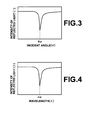
- wave number matching is achieved as the wave number vector of the evanescent light is equal to the wave number of the surface plasmon, the evanescent light and the surface plasmon resonate. Then, light energy is transferred into surface plasmons. Therefore, the intensity of the light which is totally reflected at the interface between the dielectric block and the metal film sharply drops as illustrated in FIG. 3. Generally, the drop in the intensity of the light is detected as a dark line by the light detection means.
- the resonance as described above only occurs when the incident beam is p-polarized. Therefore, it is required to set the surface plasmon resonance measurement apparatus in advance so that the light beam enters the interface in p polarization.
- the dielectric constant ⁇ s of the sample is known, the density of a specific substance in the sample can be obtained based on a predetermined calibration curve or the like. Consequently, an incident angle ⁇ sp when the intensity of the reflected light drops can be obtained. Accordingly, the dielectric constant of the sample can be obtained. Consequently, the refractive index of the sample and the physical properties corresponding to the refractive index can be obtained.
- the specific substance when a sensing material which specifically binds to a specific substance in the sample is fixed onto the metal film, if the specific substance is contained in the sample provided on the metal film, the specific substance binds to the sensing material. Accordingly, the refractive index of the sensing material changes. Therefore, the specific substance can be detected by detecting a change in the refractive index.
- a leaky mode measurement apparatus described, for example, in "Surface Refracto-sensor using Evanescent Waves: Principles and Instrumentations", by Takayuki Okamoto, Spectrum Researches, vol. 47, No. 1, 1998, pp. 21 through 23, 26 and 27 is also known as a similar measurement apparatuses utilizing the attenuated total reflection (ATR).
- the leaky mode measurement apparatus basically includes a dielectric block which is, for example, prism-shaped, a clad layer formed on a face of the dielectric block, and an optical waveguide layer which is formed on the clad layer and brought into contact with the sample.
- the leaky mode measurement apparatus also includes a light source for generating a light beam and an optical system for causing the light beam to enter the dielectric block at various angles so that total reflection. conditions are satisfied at the interface between the dielectric block and the clad layer, and attenuated total reflection occurs due to excitation of a waveguide mode in the optical waveguide layer.
- the leaky mode measurement apparatus also includes a light detection means for detecting an excitation state of the waveguide mode by measuring the intensity of the light beam which has been totally reflected at the interface.
- the excitation state of the waveguide mode is an attenuated total reflection state.
- the leaky mode measurement apparatus when the light beam is caused to enter the clad layer through the dielectric block at an incident angle which is larger than or equal to a total reflection angle, the light beam is transmitted through the clad layer. After the light beam is transmitted through the clad layer, only light which has a specific wave number, and which has entered at a specific incident angle, propagates in a waveguide mode in the optical waveguide layer. When the waveguide mode is excited as described above, most of the incident light is absorbed in the optical waveguide layer. Accordingly, attenuated total reflection, in which the intensity of light totally reflected at the interface sharply drops, occurs. The wave number of the waveguide light depends on the refractive index of the sample on the optical waveguide layer. Therefore, if the specific incident angle when the attenuated total reflection occurs is obtained, the refractive index of the sample and the properties of the sample, which are related to the refractive index, can be measured.
- the samples may be analyzed as disclosed in "Surface Plasmon Resonance Interferometry for Micro-Array Biosensing", by P. I. Nikitin, et al., EUROSENSORS XIII, 1999, pp. 235 - 238.
- the light beams are caused to enter the interface so that total reflection conditions are satisfied.
- a part of the light beams is separated into a spectrum before they enter the interface, and the spectral light beams are caused to interfere with the light beams which were totally reflected at the interface. Then, the intensity of the light beams after interference may be detected to analyze the samples.
- the part of the region is a region at which a specific substance is present on the metal film. Therefore, if parallel light which has a relatively wide cross-section of beams is used, and the distribution of the intensities of light on the cross-section of the light beams totally reflected at the interface is detected, the distribution of the specific substance within a plane along the interface can be measured. Further, as illustrated in FIG.
- the intensity of the totally reflected light becomes lower around the predetermined incident angle ⁇ sp . Therefore, the distribution of the intensities of light on the cross-section of the light beams which entered the interface at a predetermined incident angle, and which were totally reflected at the interface, shows two-dimensional distribution of the refractive indices of the substance (sample) which is present on the metal film.
- the leaky mode measurement apparatus When the leaky mode measurement apparatus is used, the attenuated total reflection occurs because of excitation of the waveguide mode in the waveguide layer instead of the surface plasmon resonance.
- other features are the same as the surface plasmon resonance measurement apparatus. Therefore, even if the leaky mode measurement apparatus is used, it is possible to obtain the two-dimensional physical properties of the sample in the same manner as the surface plasmon resonance measurement apparatus.
- the phrase "to obtain the two-dimensional physical properties of the sample” refers to obtainment of the two-dimensional physical properties of a single sample.
- the phrase also refers to obtainment of the physical properties of a plurality of the same kind of samples or various types of samples, which is two-dimensionally arranged on a thin film layer, so that the physical properties of each of the plurality of samples are obtained independently from each other.
- the light beams are caused to be totally reflected at the interface between the dielectric block and the thin film layer (the thin film layer is the metal film in the former case, and it is the clad layer and optical waveguide layer in the latter case) . Accordingly, evanescent waves which are generated in the total reflection state and the surface plasmon or the waveguide mode are coupled with each other.
- a similar surface plasmon resonance measurement apparatus and leaky mode measurement apparatus maybe configured by forming a diffraction grating on a face of the dielectric block instead of causing the light beams to be totally reflected at the face of the dielectric block.
- the refractive index of the sample and the physical properties of the sample, related to the refractive index can be analyzed by obtaining the incident angle of the light beam which enters the diffraction grating when the intensity of light attenuates.
- the surface plasmon resonance measurement apparatus and the leaky mode measurement apparatus as described above are used to analyze samples by utilizing a characteristic that an incident angle ⁇ of the light beam, when totally reflected light or reflectively diffracted light attenuates, changes according to the refractive index of the sample.
- the samples may be analyzed in a similar manner even if the incident angle ⁇ is constant. Specifically, if the incident angle ⁇ of the light beam is constant, totally reflected light or reflectively diffracted light attenuates when the wavelength ⁇ of the light beam is a specific value ⁇ sp , as illustrated in FIG. 4.
- the specific value ⁇ sp of the wavelength, when the totally reflected light or the reflectively diffracted light attenuates, is determined by the refractive index of the sample. Therefore, if the specific value ⁇ sp of the wavelength is detected, the refractive index of the sample and the physical properties of the sample, related to the refractive index, can be analyzed.
- the measurement apparatus as described above is particularly advantageous to obtain the two-dimensional physical properties of the sample. Specifically, when the two-dimensional physical properties of the sample are obtained, a light source which generates light beams, such as white light having a certain range of wavelengths, is used. Further, a two-dimensional light detection means for spectrally detecting the totally reflected light or the reflectively diffracted light is used. Since it is not required to change the incident angle of the light beam which enters the interface or the diffraction grating, a predetermined position of the sample can be stably irradiated.
- a two-dimensional image detected by the two-dimensional light detection means may be distorted.
- the aspect ratio of the two-dimensional image may be different from that of an image produced on an actual measurement plane.
- the actual measurement plane is a face of the dielectric block, on which a thin film layer (the thin film layer is a metal film in the case of the surface plasmon resonance measurement apparatus, and it is a clad layer and an optical waveguide layer in the case of the leaky mode measurement apparatus) or a diffraction grating is formed.
- the image is distorted because the light beam is refracted at a light emission plane of the prism-shaped dielectric block.
- the image is also distorted because the measurement plane is inclined with respect to the axis of the light beam.
- a method for correcting a detected image by an operation based on already-known information about the distortion of the two-dimensional image detected by the two-dimensional light detection means is disclosed in Japanese Unexamined Patent Publication No. 2001-255267.
- the detected image is corrected so that the aspect ratio of the detected image becomes the same as that of the measurement plane.
- the aspect ratio of the image can be restored by using this method.
- a first measurement apparatus is configured under the premise that the physical properties of a sample are measured by utilizing attenuation of totally reflected light as described above.
- the first measurement apparatus according to the present invention is a measurement apparatus comprising:
- a second measurement apparatus is also configured under the premise that the physical properties of a sample are measured by utilizing the attenuation of totally reflected light.
- the second measurement apparatus is a measurement apparatus comprising:
- a third measurement apparatus is configured under the premise that the physical properties of a sample are measured by utilizing the attenuation of reflectively diffracted light as described above.
- the third measurement apparatus according to the present invention is a measurement apparatus comprising:
- a fourth measurement apparatus is also configured under the premise that the physical properties of a sample are measured by utilizing the attenuation of reflectively diffracted light.
- the fourth measurement apparatus is a measurement apparatus comprising:
- a pattern produced by forming the thin film layer into a predetermined pattern may be used as the predetermined pattern.
- a predetermined pattern may be produced by forming a material, such as a thin metal film, having a refractive index which is different from that of the sample, into the predetermined pattern.
- the predetermined pattern made of the thin film layer, thin metal film, or the like may be a rectangular pattern.
- the predetermined pattern may be a cyclic pattern.
- the predetermined pattern may be formed by a concavity formed on a face of the dielectric block.
- the concavity may be, for example, dot-shaped. In that case, it is preferable that the concavity is arranged at the position of each vertex of a rectangle, or that concavities are arranged cyclically.
- the concavity as described above may be linearly shaped. In that case, it is preferable that a rectangular pattern is formed by the concavity, or that concavities are arranged cyclically.
- the light source generates a light beam which has a certain range of wavelengths.
- the two-dimensional light detection means is a means for spectrally detecting the light beam.
- a thin film layer or a diffraction grating is formed on a face of a dielectric block, which is a measurement plane.
- a predetermined pattern is formed within a region irradiated with the light beam on the face of the dielectric block.
- the first and third measurement apparatuses also include a correction means for correcting an output from a two-dimensional light detection means, based on the pattern, so that the shape of an object on the face of the dielectric block and the shape of the object, detected by the two-dimensional light detection means, are similar to each other. Therefore, it is possible to accurately recognize which part of the measurement plane is measured by producing an image based on the corrected output from the two-dimensional light detection means.
- a thin film layer or a diffraction grating is formed on a face of a dielectric block, which is a measurement plane.
- a predetermined pattern is formed within a region irradiated with the light beam on the face of the dielectric block.
- the second and fourth measurement apparatuses also include a display means for displaying an image of the predetermined pattern detected by the two-dimensional light detection means, an input means for inputting information representing a standard point in the pattern displayed on the display means, and a correction means for correcting an output from the two-dimensional detection means, based on the input information about the standard point, so that a position on the face of the dielectric block corresponds to a position on a light detection surface of the two-dimensional light detection means. Therefore, it is possible to accurately recognize which part of the measurement plane is measured by producing an image based on the corrected output from the two-dimensional light detection means.
- FIG. 1 illustrates a side view of a measurement apparatus according to a first embodiment of the present invention.
- the measurement apparatus according to the present embodiment is, for example, a surface plasmon resonance measurement apparatus as described above.
- the measurement apparatus includes a dielectric block 10 made of optical glass such as a transparent synthetic resin or BK7.
- the shape of the cross-section of the dielectric block 10 is substantially a trapezoid, for example.
- the measurement apparatus also includes a metal film 12 which is made of gold, silver, copper, aluminum, or the like, and which is formed on a face 10b (the upper side in FIG. 1) of the dielectric block 10.
- the measurement apparatus also includes a light source 14 which emits white light 13.
- the measurement apparatus also includes an incident optical system 15 for collimating the white light 13 which is emitted from the light source 14 in a divergent state.
- the incident optical system 15 further causes collimated light beams 13B to enter the dielectric block 10 so that the light beams 13B are directed to the metal film 12.
- the surface plasmon resonance measurement apparatus also includes a diffraction grating 16.
- the diffraction grating 16 is placed at a position so that the light beams 13B which were totally reflected at the interface 10a between the dielectric block 10 and the metal film 12 enter the diffraction grating 16.
- the surface plasmon resonance measurement apparatus also includes a diffraction grating drive means 17 which rotates the diffraction grating 16 in a direction (the direction of arrow A) so that the incident angle of the light beams 13B changes according to the rotation.
- the surface plasmon resonance measurement apparatus also includes a condensing lens 18 which causes the light beams 13B which were reflectively diffracted at the diffraction grating 16 to converge.
- the surface plasmon resonance measurement apparatus also includes a pinhole plate 19 which is placed at a position at which the light beams 13B converge when they are condensed by the condensing lens 18.
- the surface plasmon resonance measurement apparatus also includes a CCD (charge-coupled device) area sensor 20.
- the CCD area sensor 20 two-dimensionally detects the light beams 13B which have passed through a pinhole 19a of the pinhole plate 19.
- An output signal from the CCD area sensor 20 is input to a controller 24 of the surface plasmon resonance measurement apparatus. Then, an analysis result by the controller 24, which will be described later, is displayed on a display means 25.
- An incident angle ⁇ of the light beam 13B which enters the interface 10a should be larger than or equal to a critical angle.
- the incident angle ⁇ should be also within a range of angles as the surface plasmon is excited.
- the light beam 13B is totally reflected at the interface 10a. Further, the light beam 13B is caused to enter the interface 10a in p polarization.
- the direction of polarization of the white light 13 should be controlled by setting a wavelength plate or polarization plate in the light source 14.
- the operation of the surface plasmon resonance measurement apparatus configured as described above will be described.
- a sample 30 which is an analysis object is placed on the metal film 12.
- the light source 14 is turned on while the sample 30 is placed on the metal film 12.
- the light beams 13B which are collimated white light enter the dielectric block 10.
- the light beams 13B are totally reflected at the interface 10a between the dielectric block 10 and the metal film 12.
- the light beams 13B are emitted from the dielectric block 10, and reflectively diffracted at the diffraction grating 16. Since the diffraction angle differs depending on the wavelength ⁇ of the light beams 13B, the light beams 13B in a spatially spectral state are emitted from the diffraction grating 16.
- the spectral light beams 13B are condensed by the condensing lens 18.
- the light beams 13B pass through the pinhole 19a of the pinhole plate 19 which is placed at a position at which the light beams 13B converge, and enter the CCD area sensor 20.
- the CCD area sensor 20 detects the intensity of the light beams 13B at each position on the cross-section of the beams.
- the CCD area sensor 20 inputs a light detection signal S which represents the detected intensity of the light to the controller 24 which includes a computer system, for example.
- the light beams 13B which enter the pinhole plate 19 are spatially spectral light, as described above, light only in a certain narrow range of wavelengths passes through the pinhole 19a.
- the diffraction grating 16 is rotated as described above. Accordingly, the wavelengths of the light beams 13B which pass through the pinhole 19a are swept, and the CCD area sensor 20 detects the intensity of light for each of the wavelengths which are swept as described above.
- the controller 24 obtains the physical properties of the sample 30, such as the refractive index, based on the light detection signal S and the rotation position of the diffraction grating16, which is controlled by the controller 24.
- the relationship between the rotation position of the diffraction grating 16 and the physical properties of the sample may be obtained in advance based on experiments and experience.
- the light beam 13B two-dimensionally irradiates the metal film 12. Then, the intensity of the light beam 13B which has been totally reflected is detected at each position of the cross-section of the beam. Therefore, the controller 24 can obtain two-dimensional distribution of the physical properties, such as the refractive index, of the sample 30. Then, the display means 25 produces and displays an image based on the two-dimensional distribution of the physical properties of the sample 30, obtained by the controller 24 as described above. For example, the display means 25 displays an image within the region of the metal film 12 using various density values which reflect the physical property values, such as the refractive indices.
- FIG. 2A a plan view of the upper surface 10b of the dielectric block 10 is illustrated in FIG. 2A. Since the upper surface 10b of the dielectric block 10 is inclined with respect to the axis of the light beam 13B, the region irradiated with the light beam 13B on the upper surface 10b is oval as illustrated in FIG. 2A. Further, the light beam 13B enters the light detection surface 20a of the CCD area sensor 20 at a region of the light detection surface 20a as illustrated in FIG. 2B. The shape of the region of the light detection surface 20a, in which the light beam 13B enters, is not the same as that of the region irradiated with the light beam 13B on the upper surface 10b of the dielectric block.
- the metal film 12 has a predetermined rectangular pattern which can be placed within a region irradiated with the light beam 13B on the upper surface 10b of the dielectric block.
- the controller 24 including a computer system corrects the light detection signal S output from the two-dimensional light detection means.
- the controller 24 corrects the light detection signal S so that the shape of an object on the upper surface 10b of the dielectric block is similar to that of the object, detected by the CCD area sensor 20.
- the distribution of the physical property values is displayed on the display means 25 so that the physical property values are distributed within the region of the metal film 12, of which the shape is corrected as illustrated in FIG. 2C.
- the physical property values are distributed within the region of the metal film 12 of which the shape has been corrected. Since the distribution of the physical property values and positions on the metal film 12 correspond to each other, the problems as described above can be prevented.
- the light detection signal S is corrected as described below.
- a dielectric block 10 on which a metal film 12 similar to the one that will be used in actual analysis is prepared.
- an undistorted image of the metal film 12 is obtained and input to the controller 24.
- the undistorted image is obtained, for example, by taking a photograph of a reflected image of the upper surface of the dielectric block 10 from a position directly above the metal film 12.
- the photograph is taken with a reference CCD area sensor which is the same as the CCD area sensor 20.
- the controller 24 detects a position at which the density value changes stepwise in the image of the metal film 12, input to the controller 24. Accordingly, the controller 24 obtains an outline image of the metal film 12.
- the controller 24 stores the outline image as a template.
- the controller 24 When a sample is actually analyzed, the controller 24 performs template matching by gradually inclining the template so that the template and an obtained outline image of the metal film 12 match each other.
- the controller 24 obtains the inclination of the image of the metal film 12, detected by the CCD area sensor 20, with respect to an actual image of the metal film 12.
- the controller 24 obtains the inclination based on the inclination of the template when the template and the obtained outline image match each other. Then, the controller 24 corrects the light detection signal S output from the two-dimensional light detection means so that the inclination of the image of the metal film 12, recognized as described above, is adjusted.
- the method for correcting the light detection signal S output from the two-dimensional light detection means so that the shape of the object on the upper surface 10b of the dielectric block and that of the object, detected by the CCD area sensor 20, become similar to each other has been described.
- the method is not limited to the method as described above, and various other well-known methods for recognizing images can be applied to the present invention as appropriate.
- FIG. 5 is a side view of a measurement apparatus according to the second embodiment of the present invention.
- the same reference numerals are assigned to the elements equivalent to those of FIG. 1. Therefore, descriptions on the equivalent elements will be omitted unless such descriptions are particularly required (hereinafter, the same) .
- the apparatus according to the second embodiment of the present invention is also a surface plasmon resonance measurement apparatus, for example.
- the diffraction grating drive means 17 in the apparatus illustrated in FIG. 1 is omitted in the apparatus illustrated in FIG. 5.
- a pinhole plate drive means 40 for moving the pinhole plate 19 substantially toward the direction of the arrow C is provided in the apparatus in FIG. 5. The movement of the pinhole plate drive means 40 is controlled by the controller 24.
- the light detection signal is corrected by the controller 24 in the same manner as the first embodiment. Accordingly, a similar effect to that of the first embodiment can be achieved.
- FIG. 6 is a side view of a measurement apparatus according to the third embodiment of the present invention.
- the apparatus according to the third embodiment is also a surface plasmon resonance measurement apparatus, for example.
- the measurement apparatus according to the third embodiment is different from the apparatus illustrated in FIG. 1 in that a sensing material 50 is fixed onto the metal film 12 in the apparatus of the third embodiment, illustrated in FIG. 6.
- the sensing material 50 is a material which specifically binds to a specific substance in a specimen 51 which will be described later.
- the specimen 51 is placed on the sensing material 50. If the specific substance is contained in the specimen 51, the specific substance binds to the sensing material 50, and the refractive index of the sensing material 50 changes. Therefore, the wavelengths of the light beam 13B which enters the CCD area sensor 20 in a similar manner to the operations in the apparatus illustrated in FIG. 1 are swept both before and after the specimen 51 is placed on the sensing material 50. Consequently, it is detected whether the wavelength ⁇ sp when the totally reflected light attenuates is different between before and after placement of the specimen 51 on the sensing material 50. Accordingly, it is possible to analyze whether the sensing material 50 has bound to the specific substance. Specifically, it is possible to analyze whether the specific substance is contained in the specimen 51.
- the light detection signal S is corrected by the controller 24 in the same manner as the first embodiment. Therefore, a similar effect to that of the first embodiment can be achieved.
- the CCD area sensor 20 which measures the distribution of the intensities of light on the cross-section of the light beam 13B is used in the present embodiment. Therefore, it is possible to recognize at which part of the specimen 51 the sensing material 50 and the specific substance have bound to each other.
- a plurality of types of sensing materials may be fixed onto the metal film 12 at appropriate intervals instead of fixing a kind of sensing material 50 onto the metal film 12 as described above. If the plurality of types of sensing materials is fixed onto the metal film 12, it is possible to recognize, based on an output from the CCD area sensor 20, at which position of the metal film 12 the sensing material and the specific substance have bound to each other. Specifically, it is possible to recognize which kind of sensing material has bound to the specific substance.
- a plurality of a kind of sensing materials may be fixed onto the metal film 12 at appropriate intervals instead of fixing the plurality to types of sensing materials as described above. If a different specimen is provided for each of the sensing materials, it is possible to recognize, based on an output from the CCD area sensor 20, at which position of the metal film 12 the sensing material and the specific substance have bound to each other. Specifically, it is possible to recognize which specimen has bound to the sensing material.
- the binding between the sensing material and the specific substance as described above is, for example, binding between various antibodies and antigens.
- FIG. 7 illustrates a side view of a measurement apparatus according to the fourth embodiment of the present invention.
- the apparatus according to the fourth embodiment is also a surface plasmon resonance measurement apparatus, for example.
- FIG. 1 and FIG. 7 are different from each other in that a dielectric block 60 is used in the measurement apparatus of FIG. 7 instead of the dielectric block 10.
- the shape of the dielectric block 60 is a rectangular parallelepiped, and a diffraction grating 61 for light entering the dielectric block 60 and a diffraction grating 62 for light emitted from the dielectric block 60 are formed on the lower surface of the dielectric block 60.
- the light beam 13B is diffracted at the diffraction grating 61 for light entering the dielectric block 60.
- the diffracted light enters the interface 10a at an incident angle which can cause the light beam 13B to be totally reflected.
- the light is diffracted at the diffraction grating 62 for light emitted from the dielectric block 60, and the diffracted light is emitted from the dielectric block 60.
- Other features of the measurement apparatus in the present embodiment are basically the same as those of the apparatus illustrated in FIG. 1.
- a metal film 12 which has a predetermined rectangular pattern is also placed within a region irradiated with the light beam 13B on an upper surface 60b of the dielectric block 60.
- the controller 24 corrects the light detection signal S in the same manner as the first embodiment. Therefore, a similar effect to that of the first embodiment can be achieved.
- FIG. 8 illustrates a side view of a measurement apparatus according to the fifth embodiment of the present invention.
- the apparatus according to the fifth embodiment is also a surface plasmon resonance measurement apparatus, for example.
- the measurement apparatus according to the fifth embodiment and the measurement apparatus illustrated in FIG. 1 are different from each other in that a dielectric block 70 is provided in the measurement apparatus illustrated in FIG. 8 instead of the dielectric block 10 in the apparatus illustrated in FIG. 1.
- a diffraction grating 71 is formed on the upper surface (the surface on which the metal film is formed) of the dielectric block 70.
- the diffraction grating 71 is produced by forming uneven patterns on the upper surface of the dielectric block 70.
- a typical height and pitch of the uneven patterns is approximately several tens of nanometers (nm) and 1 ⁇ m, respectively.
- the light beam 13B is reflectively diffracted by the diffraction grating 71, and bounced.
- the wavelength ⁇ of the light beam 13B is a specific value ⁇ sp
- evanescent light which is generated by the diffraction, and which penetrates the metal film 12 interacts with the surface plasmon.
- the intensity of the light beam 13B which is reflectively diffracted toward the dielectric block 70 sharply drops. Therefore, the refractive index of the sample 30 and the properties of the sample 30, which are related to the refractive index, can be analyzed by this apparatus in a similar manner to the apparatus illustrated in FIG. 1.
- a metal film 12 which has a predetermined rectangular pattern is also formed within the region irradiated with the light beam 13B on the diffraction grating 71.
- the controller 24 corrects the light detection signal S in the same manner as the first embodiment. Accordingly, a similar effect to that of the first embodiment can be achieved.
- FIG. 9 illustrates a side view of a measurement apparatus according to the sixth embodiment of the present invention.
- the apparatus according to the sixth embodiment is a leaky mode measurement apparatus as described above.
- the leaky mode measurement apparatus in FIG. 9 and the measurement apparatus illustrated in FIG. 1 are different from each other in that a clad layer 80 and an optical waveguide layer 81 are provided in this order on the upper surface 10b of the dielectric block 10 of the apparatus illustrated in FIG. 9 instead of the metal film 12.
- the dielectric block 10 is made of optical glass such as a transparent synthetic resin or BK7.
- the clad layer 80 is a thin film layer made of a dielectric material which has a refractive index lower than that of the dielectric block 10 or a metal such as gold.
- the optical waveguide layer 81 is also a thin film layer.
- the optical waveguide layer 81 is made of a dielectric material, such as PMMA (polymethylmethacrylate), which has a refractive index higher than that of the clad layer 80.
- the thickness of the clad layer 80 is 36.5 nm when the clad layer is, for example, made of a metal film.
- the thickness of the optical waveguide layer 81 is approximately 700 nm when the optical waveguide layer 81 is, for example, made of PMMA.
- the leaky mode measurement apparatus configured as described above, if the light beam 13B is caused to enter the clad layer 80 through the dielectric block 10 at an incident angle which is larger than or equal to a critical angle, the light beam 13B is totally reflected at the interface 10c between the dielectric block 10 and the clad layer 80. However, light which has a specific wavelength is transmitted through the clad layer 80 and enters the optical waveguide layer 81. Then, the light propagates through the optical waveguide layer 81 in a waveguide mode. When the waveguide mode is excited as described above, most of the incident light is absorbed in the optical waveguide layer 81. Therefore, the intensity of light totally reflected at the interface 10c sharply drops, and attenuated total reflection occurs.
- the wave number of the waveguide light in the optical waveguide layer 81 depends on the refractive index of the sample 30 on the optical waveguide layer 81. Therefore, if the specific wavelength when the attenuated total reflection occurs is obtained within the range of swept wavelengths, the refractive index of the sample 30 and the physical properties of the sample 30, related to the refractive index, can be analyzed. Particularly, in the present embodiment, the intensity of the light beam 13B is detected by the CCD area sensor 20 at each position on the cross-section of the beam. Therefore, the controller 24 can obtain the two-dimensional distribution of the physical properties of the sample 30, such as the refractive index. The two-dimensional distribution of the physical properties of the sample 30, obtained by the controller 24 as described above, is displayed on the display means 25.
- the clad layer 80 and the optical waveguide layer 81 are produced so that they have a predetermined rectangular pattern within the region irradiated with the light beam 13B on the upper surface 10b of the dielectric block 10.
- the controller 24 corrects the light detection signal S in the same manner as the first embodiment. Therefore, a similar effect to that of the first embodiment can be achieved.
- FIG. 10 illustrates a side view of a measurement apparatus according to the seventh embodiment of the present invention.
- the apparatus according to the seventh embodiment is, for example, a surface plasmon resonance measurement apparatus.
- the measurement apparatus in the present embodiment and the measurement apparatus illustrated in FIG. 1 are different from each other in that an input means 23, such as a keyboard, for inputting information is provided in the controller 24 in the present embodiment.
- an image including an image of the metal film 12 is displayed on the display means 25 based on the light detection signal S output from the CCD area sensor 20.
- An operator of the apparatus looks at the displayed image, and inputs information representing a standard point of the metal film 12 which has a predetermined rectangular pattern to the controller 24.
- the information representing the standard point of the metal film 12 is, for example, information representing the pixel position of each of four vertices of the metal film 12.
- Information such as that the standard points are, for example, vertices of a square of 1 cm X 1 cm has been stored in the controller 24.
- the controller 24 corrects the light detection signal S output from the CCD area sensor 20 so that the pixel positions input by the operator become the vertices of the square stored in the controller 24. Accordingly, the positions on the metal film 12 and the positions on the light detection surface of the CCD area sensor 20 correspond to each other also in this case. Therefore, the distribution of the physical properties is displayed on the display means 25 so that the physical properties accurately correspond to the positions on the metal film 12.
- the correction method according to the seventh embodiment may be also applied to measurement apparatuses which are basically configured as described in the second through sixth embodiments of the present invention.
- the correction method according to the seventh embodiment is applied to these measurement apparatuses, effects similar to the effect as described above may be achieved.
- a predetermined pattern formed in the measurement apparatus according to the present invention is not limited to a rectangular pattern made of the metal film 12, as described above.
- the predetermined pattern may be made of a plurality of metal films 12' which are arranged cyclically, for example, as illustrated in FIG. 11.
- the metal film 12 may be formed on the entire upper surface 10b of the dielectric block 10. Then, a predetermined pattern 90 made of a material which has a refractive index different from that of the sample, which is an analysis object, may be formed on the metal film 12. More specifically, the metal film 12 may be formed so that it has a uniform thickness of 50 nm, for example. Further, a predetermined pattern 90 which is made of a thin film of SiO 2 , and which has a thickness of 1 nm, may be formed within a region irradiated with the light beam 13B on the metal film 12. The reflection properties of the pattern 90 as described above are different from those of the area surrounding the pattern 90.
- the outline of the pattern can be easily discriminated.
- the material which has a refractive index different from that of the sample, as described above is not limited to the thin film of SiO 2 .
- the pattern may be also formed by a relatively thick metal film.
- the pattern made of the material as described above may be formed so that they are arranged cyclically as illustrated in FIG. 11.
- a dot-shaped concavity 91 may be formed in the region of the metal film 12, as illustrated in FIG. 13.
- the dot-shaped concavity 91 may be used as the predetermined pattern.
- the total reflection and diffracted reflection as described above do not occur in a part of the upper surface 10b, at which the concavity 91 is formed, and the reflectance drops. Therefore, the position of the concavity 91 can be easily detected. It is preferable that the concavity 91 as described above is formed, for example, at a vertex of a rectangle to detect a position on the measurement plane.
- the concavity as described above may be a groove which forms a linear or rectangular pattern. Further, a plurality of dot-shaped or linearly-shaped concavities may be formed and arranged cyclically.
Applications Claiming Priority (1)
| Application Number | Priority Date | Filing Date | Title |
|---|---|---|---|
| JP2004197667A JP2006017648A (ja) | 2004-07-05 | 2004-07-05 | 測定装置 |
Publications (1)
| Publication Number | Publication Date |
|---|---|
| EP1615018A1 true EP1615018A1 (de) | 2006-01-11 |
Family
ID=35063031
Family Applications (1)
| Application Number | Title | Priority Date | Filing Date |
|---|---|---|---|
| EP20050014461 Withdrawn EP1615018A1 (de) | 2004-07-05 | 2005-07-04 | Oberflächenplasmonenresonanzmessgerät mit Korrektur des Ausgangssignals eines zweidimensionalen Lichtdetektionsmittels |
Country Status (3)
| Country | Link |
|---|---|
| US (2) | US7551286B2 (de) |
| EP (1) | EP1615018A1 (de) |
| JP (1) | JP2006017648A (de) |
Cited By (3)
| Publication number | Priority date | Publication date | Assignee | Title |
|---|---|---|---|---|
| FR2943430A1 (fr) * | 2009-03-19 | 2010-09-24 | Ifremer | Optode pour un transducteur optique |
| EP2667181A4 (de) * | 2011-01-20 | 2015-12-23 | Nat Inst Of Advanced Ind Scien | Sensorvorrichtung |
| CN110702642A (zh) * | 2019-10-29 | 2020-01-17 | 西南大学 | 一种微井结构SPRi芯片的制备方法及其产品和应用 |
Families Citing this family (18)
| Publication number | Priority date | Publication date | Assignee | Title |
|---|---|---|---|---|
| US7598483B2 (en) * | 2005-02-02 | 2009-10-06 | Panasonic Corporation | Optical element and optical measurement device using the optical element |
| KR100701006B1 (ko) * | 2005-05-31 | 2007-03-29 | 한국전자통신연구원 | 포물선 도파로형 평행광 렌즈 및 이를 포함한 파장 가변외부 공진 레이저 다이오드 |
| US20090010589A1 (en) * | 2005-08-30 | 2009-01-08 | Robertson William M | Optical sensor based on surface electromagnetic wave resonance in photonic band gap materials |
| US20070176728A1 (en) * | 2006-01-31 | 2007-08-02 | Ranganath Tirumala R | Tiled periodic metal film sensors |
| JP2007263901A (ja) * | 2006-03-30 | 2007-10-11 | Dkk Toa Corp | 表面プラズモン共鳴測定装置 |
| JP4843543B2 (ja) * | 2007-03-28 | 2011-12-21 | 株式会社日立ハイテクノロジーズ | 蛍光検出装置及び方法 |
| US7570362B2 (en) | 2007-09-28 | 2009-08-04 | Olympus Corporation | Optical measurement apparatus utilizing total reflection |
| JP5068206B2 (ja) * | 2008-03-24 | 2012-11-07 | 富士フイルム株式会社 | 質量分析装置 |
| US8110796B2 (en) | 2009-01-17 | 2012-02-07 | The George Washington University | Nanophotonic production, modulation and switching of ions by silicon microcolumn arrays |
| US9490113B2 (en) * | 2009-04-07 | 2016-11-08 | The George Washington University | Tailored nanopost arrays (NAPA) for laser desorption ionization in mass spectrometry |
| US9255883B2 (en) | 2009-10-05 | 2016-02-09 | Konica Minolta, Inc. | Surface plasmon-enhanced fluorescence measuring apparatus |
| FR2982028B1 (fr) | 2011-10-26 | 2020-02-21 | Aryballe Technologies | Puce microstructuree comprenant des surfaces convexes pour analyse par resonance des plasmons de surface, dispositif d'analyse contenant ladite puce microstructuree et utilisation dudit dispositif |
| FR2982027B1 (fr) | 2011-10-26 | 2014-01-03 | Thibaut Mercey | Puce microstructuree pour analyse par resonance des plasmons de surface, dispositif d'analyse comprenant ladite puce microstructuree et utilisation dudit dispositif |
| JP5919917B2 (ja) * | 2012-03-16 | 2016-05-18 | 富士ゼロックス株式会社 | 濃度検出装置及び画像形成装置 |
| CN104535545B (zh) * | 2014-12-31 | 2017-05-17 | 中国科学技术大学 | 一种基于金属薄膜spr色散的图像化测量装置和测量方法 |
| JP6428516B2 (ja) * | 2015-07-09 | 2018-11-28 | 株式会社島津製作所 | 分光検出器 |
| ITUA20161345A1 (it) * | 2016-03-04 | 2017-09-04 | Eltek Spa | Dispositivo sensore per contenitori di sostanze liquide |
| DE102020135131B4 (de) * | 2020-12-30 | 2023-04-20 | Multivac Sepp Haggenmüller Se & Co. Kg | Umlenkeinrichtung für Produkte |
Citations (5)
| Publication number | Priority date | Publication date | Assignee | Title |
|---|---|---|---|---|
| JP2001255267A (ja) * | 2000-03-10 | 2001-09-21 | Kanagawa Acad Of Sci & Technol | 2次元イメージング表面プラズモン共鳴測定装置および測定方法 |
| US20010026943A1 (en) * | 2000-02-22 | 2001-10-04 | Stefan Dickopf | SPR sensor system |
| JP2002286632A (ja) * | 2001-03-23 | 2002-10-03 | Japan Science & Technology Corp | 測定試料の光学的評価方法およびその装置 |
| JP2002357542A (ja) * | 2001-06-01 | 2002-12-13 | Mitsubishi Chemicals Corp | 分析素子、並びにそれを用いた試料の分析方法 |
| US20030179379A1 (en) * | 2001-12-21 | 2003-09-25 | Erk Gedig | Device and method for the examination of thin layers |
Family Cites Families (8)
| Publication number | Priority date | Publication date | Assignee | Title |
|---|---|---|---|---|
| JPH06167443A (ja) | 1992-10-23 | 1994-06-14 | Olympus Optical Co Ltd | 表面プラズモン共鳴を利用した測定装置 |
| JP3422063B2 (ja) | 1994-01-28 | 2003-06-30 | 松下電器産業株式会社 | 画像処理装置 |
| SE9700384D0 (sv) | 1997-02-04 | 1997-02-04 | Biacore Ab | Analytical method and apparatus |
| JP2001045244A (ja) | 1999-07-29 | 2001-02-16 | Hitachi Ltd | 画像読取装置 |
| US6992770B2 (en) * | 2001-01-25 | 2006-01-31 | Fuji Photo Film Co., Ltd. | Sensor utilizing attenuated total reflection |
| US7030988B2 (en) * | 2001-03-22 | 2006-04-18 | Fuji Photo Film Co., Ltd. | Measuring apparatus and measuring chip |
| US6697158B2 (en) * | 2001-04-03 | 2004-02-24 | Fuji Photo Film Co., Ltd. | Measuring apparatus utilizing attenuated total reflection |
| JP2004117298A (ja) * | 2002-09-27 | 2004-04-15 | Fuji Photo Film Co Ltd | 全反射減衰を利用した測定方法および測定装置 |
-
2004
- 2004-07-05 JP JP2004197667A patent/JP2006017648A/ja active Pending
-
2005
- 2005-07-01 US US11/171,420 patent/US7551286B2/en not_active Expired - Fee Related
- 2005-07-04 EP EP20050014461 patent/EP1615018A1/de not_active Withdrawn
-
2009
- 2009-01-27 US US12/360,740 patent/US7812957B2/en not_active Expired - Fee Related
Patent Citations (5)
| Publication number | Priority date | Publication date | Assignee | Title |
|---|---|---|---|---|
| US20010026943A1 (en) * | 2000-02-22 | 2001-10-04 | Stefan Dickopf | SPR sensor system |
| JP2001255267A (ja) * | 2000-03-10 | 2001-09-21 | Kanagawa Acad Of Sci & Technol | 2次元イメージング表面プラズモン共鳴測定装置および測定方法 |
| JP2002286632A (ja) * | 2001-03-23 | 2002-10-03 | Japan Science & Technology Corp | 測定試料の光学的評価方法およびその装置 |
| JP2002357542A (ja) * | 2001-06-01 | 2002-12-13 | Mitsubishi Chemicals Corp | 分析素子、並びにそれを用いた試料の分析方法 |
| US20030179379A1 (en) * | 2001-12-21 | 2003-09-25 | Erk Gedig | Device and method for the examination of thin layers |
Non-Patent Citations (3)
| Title |
|---|
| PATENT ABSTRACTS OF JAPAN vol. 2000, no. 26 1 July 2002 (2002-07-01) * |
| PATENT ABSTRACTS OF JAPAN vol. 2003, no. 02 5 February 2003 (2003-02-05) * |
| PATENT ABSTRACTS OF JAPAN vol. 2003, no. 04 2 April 2003 (2003-04-02) * |
Cited By (4)
| Publication number | Priority date | Publication date | Assignee | Title |
|---|---|---|---|---|
| FR2943430A1 (fr) * | 2009-03-19 | 2010-09-24 | Ifremer | Optode pour un transducteur optique |
| EP2667181A4 (de) * | 2011-01-20 | 2015-12-23 | Nat Inst Of Advanced Ind Scien | Sensorvorrichtung |
| CN110702642A (zh) * | 2019-10-29 | 2020-01-17 | 西南大学 | 一种微井结构SPRi芯片的制备方法及其产品和应用 |
| CN110702642B (zh) * | 2019-10-29 | 2022-03-18 | 西南大学 | 一种微井结构SPRi芯片的制备方法及其产品和应用 |
Also Published As
| Publication number | Publication date |
|---|---|
| US7812957B2 (en) | 2010-10-12 |
| US20060001884A1 (en) | 2006-01-05 |
| US20090141283A1 (en) | 2009-06-04 |
| US7551286B2 (en) | 2009-06-23 |
| JP2006017648A (ja) | 2006-01-19 |
Similar Documents
| Publication | Publication Date | Title |
|---|---|---|
| US7551286B2 (en) | Measurement apparatus | |
| US6992770B2 (en) | Sensor utilizing attenuated total reflection | |
| US7339681B2 (en) | Surface plasmon resonance microscope using common-path phase-shift interferometry | |
| US7382461B2 (en) | Analysis method and apparatus utilizing attenuated total reflection | |
| US6791691B2 (en) | Measuring method and apparatus using attenuation in total internal reflection | |
| US20070047088A1 (en) | Optical sensor based on surface electromagnetic wave resonance in photonic band gap materials and method for using same | |
| US20080218860A1 (en) | Optical sensor based on surface electromagnetic wave resonance in photonic band gap materials | |
| US7144153B2 (en) | Measuring apparatus | |
| JP3399804B2 (ja) | 表面プラズモンセンサー | |
| US20030090668A1 (en) | Measuring method and apparatus using attenuation in total internal reflection | |
| US7057731B2 (en) | Measuring method and apparatus using attenuated total reflection | |
| JP2000180353A (ja) | 表面プラズモンセンサー | |
| JP2004527741A (ja) | 全反射分光法のための装置および方法 | |
| JP3903432B2 (ja) | 測定装置 | |
| US11656177B2 (en) | Optical nanostructure sensing device and image analysis method | |
| US20220317028A1 (en) | Method and device for analysing a sample, implementing a resonant support | |
| US7330263B2 (en) | Measurement method and apparatus | |
| US20030184755A1 (en) | Measuring chip | |
| JP4173746B2 (ja) | 測定装置 | |
| JP2003057173A (ja) | 表面プラズモン共鳴を利用した試料の分析方法及び分析装置、並びに表面プラズモン共鳴センサチップ | |
| JP3945636B2 (ja) | 測定装置 | |
| JP3910498B2 (ja) | 測定装置 | |
| US20230349826A1 (en) | Background insensitive reflectometric optical methods and systems using the same | |
| JP2007192841A (ja) | 全反射減衰を利用した測定方法および測定装置 | |
| JP2004085488A (ja) | 測定装置 |
Legal Events
| Date | Code | Title | Description |
|---|---|---|---|
| PUAI | Public reference made under article 153(3) epc to a published international application that has entered the european phase |
Free format text: ORIGINAL CODE: 0009012 |
|
| AK | Designated contracting states |
Kind code of ref document: A1 Designated state(s): AT BE BG CH CY CZ DE DK EE ES FI FR GB GR HU IE IS IT LI LT LU LV MC NL PL PT RO SE SI SK TR |
|
| AX | Request for extension of the european patent |
Extension state: AL BA HR MK YU |
|
| 17P | Request for examination filed |
Effective date: 20060711 |
|
| 17Q | First examination report despatched |
Effective date: 20060811 |
|
| AKX | Designation fees paid |
Designated state(s): CH DE FR GB LI SE |
|
| RAP1 | Party data changed (applicant data changed or rights of an application transferred) |
Owner name: FUJIFILM CORPORATION |
|
| STAA | Information on the status of an ep patent application or granted ep patent |
Free format text: STATUS: THE APPLICATION IS DEEMED TO BE WITHDRAWN |
|
| 18D | Application deemed to be withdrawn |
Effective date: 20130810 |