EP1614557B1 - Anhängekupplung für Kraftfahrzeuge - Google Patents
Anhängekupplung für Kraftfahrzeuge Download PDFInfo
- Publication number
- EP1614557B1 EP1614557B1 EP05014641A EP05014641A EP1614557B1 EP 1614557 B1 EP1614557 B1 EP 1614557B1 EP 05014641 A EP05014641 A EP 05014641A EP 05014641 A EP05014641 A EP 05014641A EP 1614557 B1 EP1614557 B1 EP 1614557B1
- Authority
- EP
- European Patent Office
- Prior art keywords
- bearing head
- ball
- ball rod
- rod bearing
- counterstops
- Prior art date
- Legal status (The legal status is an assumption and is not a legal conclusion. Google has not performed a legal analysis and makes no representation as to the accuracy of the status listed.)
- Expired - Lifetime
Links
Images




Classifications
-
- B—PERFORMING OPERATIONS; TRANSPORTING
- B60—VEHICLES IN GENERAL
- B60D—VEHICLE CONNECTIONS
- B60D1/00—Traction couplings; Hitches; Draw-gear; Towing devices
- B60D1/48—Traction couplings; Hitches; Draw-gear; Towing devices characterised by the mounting
- B60D1/54—Traction couplings; Hitches; Draw-gear; Towing devices characterised by the mounting collapsible or retractable when not in use, e.g. hide-away hitches
-
- B—PERFORMING OPERATIONS; TRANSPORTING
- B60—VEHICLES IN GENERAL
- B60D—VEHICLE CONNECTIONS
- B60D1/00—Traction couplings; Hitches; Draw-gear; Towing devices
- B60D1/01—Traction couplings or hitches characterised by their type
- B60D1/06—Ball-and-socket hitches
Definitions
- the invention relates to a towing hitch for motor vehicles, comprising a vehicle fixedly arranged, pivotally and axially displaceably mounted ball bar, which carries at its free end a coupling ball and both in its rest position and in its operating position about engageable form-fitting contours on the one hand a ball rod bearing head and on the other hand a this opposite component is rotatably secured, wherein the ball rod bearing head is formed with stop means, which are associated with lying in its pivotal counter-stops which limit the pivotal movement of the ball rod bearing head in the operating position and in the rest position of the ball rod, as from EP 1 142 732 A1 known.
- hitch ball bearing head is mounted on a mounting flange mounted on the hollow shaft, which is centrally integrated with an axially acting locking of the ball rod bearing head for engaging the positive locking contours both in the operating position and in the rest position of the ball rod is formed.
- the axially acting lock allows an automatic axial forced displacement of the ball bar, as soon as the blocking is released in a rotary end position. This happens when a blocking bolt is disengaged or released via an externally actuable pressure or traction means.
- the ball rod can be pivoted manually or motor driven in the desired rotational end position and lock by advancing the locking pin.
- the ball rod is then fixed by means of the positive connection non-rotatably .
- the positive connection in one by the DE 198 59 961 A1 become known hitch this consists for example of a toothing and a counter toothing, engages in the rotational end positions of Kugeistangenlagerkopfes each other.
- the invention has for its object to provide a generic trailer coupling, which offers even greater reliability.
- a preferred embodiment of the invention provides that the counterstops are formed with an engagement contour which imposes an axial movement component on the abutment means of the ball-rod bearing head, and which merges into a stop contour terminating the movements.
- the stop means advantageous two spaced, over the ball rod bearing head radially protruding bolts which cooperate with them arranged in the respective pivoting direction of the ball bearing head counter-stop are due to the shape of the engagement contour with the beginning of the emergence of a stop means on the counter-attack targeted axially Direction of the positive connection acted upon.
- This additional movement component which thus temporarily overlaps the pivoting movement of the ball-rod bearing head, is terminated when the abutment means has reached the abutment contour at the foot of the engagement contour.
- the expiration of the stop means according to the invention on an engagement contour ensures the automatic axial displacement of the ball rod bearing head in its form-locking connection even if a force is manually generated and maintained against the locking direction at a manually pivotable ball rod at the end of the respective pivoting operation (operating position or rest position) ,
- the counter-attacks can be arranged according to an embodiment of the invention advantageously on components of a vehicle mounted on the already required trailer hitch cross member, but also provide elsewhere, for. B. integrated into the pivot system or the ball rod bearing head.
- components are the mounting flange and / or a connecting plate to the cross member or support frame of the hitch ago.
- the respective rotational end position (operating or rest position) locking positive connection 5 consists in the embodiment of arranged in the ball rod bearing head 2 balls 6 and this in the opposite mounting flange 3 associated, not shown spherical caps, in which engage the balls 6 and the Set ball bearing head 2 or the ball rod so that it rotates.
- the conical ball rod bearing head 2 is here with stop means 7 in the form of two projecting beyond its largest diameter, ie radially projecting, spaced bolts 8a and 8b provided.
- the bolt 8a, 8b are associated with the pivoting of the ball rod bearing head 2 in its trajectory lying counter stops 9 and 10, namely the bolt 8a of the rotational end position of the operating position of the trailer coupling 1 and the ball rod bearing head 2 defining, attached to the mounting flange 3 counter-stop 9, as well the bolt 8b of the formed on the connecting plate 4, the rotational end position to the rest position of the trailer coupling 1 and the ball rod bearing head 2 defining counter-stop 10th
- Both the counter-stop 9 and the counter-stop 10 are formed with an engagement contour 11 a and 11 b and also a stop contour 12 a and 12 b (see Fig. 1 and 7 ).
- the ball-rod bearing head 2 due to the shape of the engagement contours 11 a, 11 b imposed an axial movement component, the engagement of the balls 6 in the spherical caps of the positive connection 5 causes.
- Fig. 7 to 12 consecutive operating phases Fig. 1 to 6 can the function of the counter-stop 9 in cooperation with the bolt 8a as a rotary end stop and engaging aid for locking the trailer hitch 1 in the operating position of the ball bearing head 2 with ball bar and the Fig. 7 to 12 take the same function in the interaction of bolt 8b and counter-stop 10 for fixing the rest position of the trailer coupling 1 and the ball-rod bearing head 3 with ball bar.
Landscapes
- Engineering & Computer Science (AREA)
- Transportation (AREA)
- Mechanical Engineering (AREA)
- Pivots And Pivotal Connections (AREA)
- Agricultural Machines (AREA)
- Fertilizing (AREA)
Description
- Die Erfindung betrifft eine Anhängekupplung für Kraftfahrzeuge, umfassend eine fahrzeugfest angeordnete, schwenkbar sowie axial verschieblich gelagerte Kugelstange, die an ihrem freien Ende eine Kupplungskugel trägt und sowohl in ihrer Ruhelage als auch in ihrer Betriebslage über in Eingriff bringbare Formschlußkonturen einerseits eines Kugelstangenlagerkopfes und andererseits eines diesem gegenüber liegenden Bauteiles drehfest festlegbar ist, wobei der Kugelstangenlagerkopf mit Anschlagmitteln ausgebildet ist, denen in seiner Schwenkbahn liegende Gegenanschläge zugeordnet sind, die in der Betriebsstellung und in der Ruhestellung der Kugelstange die Schwenkbewegung des Kugelstangenlagerkopfes begrenzen, wie aus der
EP 1 142 732 A1 bekannt. - Bei einer durch die
DE 102 52 722 B3 bekannt gewordenen Anhängekupplung ist der Kugelstangenlagerkopf auf einer am Anbauflansch befestigten Hohlwelle angeordnet, die zentral integriert mit einer axial wirkenden Verriegelung des Kugelstangenlagerkopfes zum in Eingriff bringen der Formschlusskonturen sowohl in der Betriebslage als auch in der Ruhelage der Kugelstange ausgebildet ist. Die axial wirkende Verriegelung ermöglicht eine selbsttätige axiale Zwangsverschiebung der Kugelstange, sobald die Sperrung in einer Drehendlage aufgehoben wird. Dies dann, wenn über ein von außen betätigbares Druck- oder Zugmittel ein Sperrbolzen ausgerückt bzw. freigegeben wird. Das kann mittels beispielsweise eines Handrades, wie aus derDE-U-94 08 478.5 bekannt, ausgelöst werden, indem eine Zahnstange einen Bowdenzug als Verbindung zum Sperrbolzen betätigt, so dass der Sperrbolzen zurückgezogen wird. Durch das Zurückziehen des Sperrbolzens kommt die Kugelstange aus ihrer Formschlussverbindung, hier in Form von Kugeln und im gegenüberliegenden Bauteil komplementären Kalotten, von Befestigungs- und Anbauflansch frei und kann nach dem Entriegeln somit unter der Schwerkraft bei gleichzeitiger axialer Verschiebung in eine Zwischenposition schwenken. - Aus der Zwischenposition heraus lässt sich die Kugelstange manuell oder motorbetrieben in die gewünschte Drehendlage verschwenken und durch Vorrücken des Sperrbolzens verriegeln. Sowohl in der Ruhelage, in welcher sich die Kugelstange in etwa quer zur Fahrzeuglängsrichtung unter dem Stoßfänger bzw. der Heckschürze befindet, als auch in der Betriebslage, in welcher sich die Kugelstange im wesentlichen in Fahrzeuglängsrichtung befindet, wird die Kugelstange dann mittels der Formschlussverbindung unverdrehbar festgelegt. Die Formschlussverbindung, bei einer durch die
DE 198 59 961 A1 bekannt gewordenen Anhängekupplung besteht diese beispielsweise aus einer Verzahnung sowie einer Gegenverzahnung, greift in den Drehendstellungen des Kugeistangenlagerkopfes ineinander. - Der Erfindung liegt die Aufgabe zugrunde, eine gattungsgemäße Anhängekupplung zu schaffen, die eine noch größere Betriebssicherheit bietet.
- Diese Aufgabe wird erfindungsgemäß dadurch gelöst, dass die Gegenanschläage gleichzeitig zum axialen Einrücken des Kugelstangenlagerkopfes in die Formschlussverbindung der Formschlusskonturen ausgebildet sind. Es lässt sich hiermit erreichen, dass die Elemente - Kugeln und Kalotten oder Verzahnung und Gegenverzahnung oder dergleichen - der Formschlussverbindung stets eine deckungsgleiche Stellung einnehmen und ein ungestörtes, ordnungsgemäßes I-neingriffbringen der Formschlusselemente exakt gewährleistet wird. Außerdem wird damit die gleichzeitige selbsttätige axiale Zwangsverschiebung der Kugelstange begünstigt bzw. unterstützt.
- Eine bevorzugte Ausführung der Erfindung sieht vor, dass die Gegenanschläge mit einer den Anschlagmitteln des Kugelstangenlagerkopfes beim Auftreffen eine axiale Bewegungskomponente auferlegenden Einrückkontur ausgebildet sind, die in eine die Bewegungen beendende Anschlagkontur übergeht. Die Anschlagmittel, vorteilhafte zwei im Abstand voneinander angeordnete, über den Kugelstangenlagerkopf radial herausragende Bolzen, die mit einem ihnen in der jeweiligen Schwenkrichtung des Kugelstangenlagerkopfes angeordneten Gegenanschlag zusammenwirken, werden aufgrund der Formgebung der Einrückkontur mit dem Beginn des Auflaufens eines Anschlagmittels auf den Gegenanschlag gezielt axial in Richtung der Formschlussverbindung beaufschlagt. Diese zusätzliche Bewegungskomponente, die sich der Schwenkbewegung des Kugelstangenlagerkopfes somit temporär überlagert, wird dann beendet, wenn das Anschlagmittel die Anschlagkontur am Fuß der Einrückkontur erreicht hat. Das erfindungsgemäße Ablaufen des Anschlagmittels auf einer Einrückkontur stellt die automatische axiale Verschiebung des Kugelstangenlagerkopfes in seine Formschlussverbindung selbst dann sicher, wenn bei einer manuell verschwenkbaren Kugelstange am Ende des jeweiligen Schwenkvorganges (Betriebsstellung oder Ruhestellung) von Hand eine Kraft entgegen der Verriegelungsrichtung erzeugt und aufrecht erhalten würde.
- Die Gegenanschläge lassen sich nach einer Ausgestaltung der Erfindung vorteilhaft an Bauteilen eines am Fahrzeug montierten, ohnehin erforderlichen Anhängerkupplungs-Querträgers anordnen, aber auch an anderer Stelle vorsehen, z. B. integriert in das Schwenksystem bzw. den Kugelstangenlagerkopf. Als solche Bauteile liegen der Anbauflansch und/oder ein Verbindungsblech zum Querträger bzw. Traggestell der Anhängevorrichtung vor.
- Weitere Merkmale und Einzelheiten der Erfindung ergeben sich aus den Ansprüchen und der Beschreibung eines in den Zeichnungen dargestellten Ausführungsbeispiels der Erfindung. Es zeigen:
- Fig. 1
- in einer Seitenansicht eine Anhängekupplung, aus Gründen der besseren Übersicht ohne Kugelstangenhals und Kupplungskugel dargestellt, von der ein schwenkbarer Kugelstangenlagerkopf mit zwei umfangsverteilt angeordneten Anschlagmitteln und diesen im Schwenkweg des Kugelstangenlagerkopfes zugeordneten Gegenanschlägen zu erkennen ist, in einer Anfangsposition des Kugelstangenlagerkopfes zu dessen Festlegung in der Betriebslage durch Einrücken einer Formschlußverbindung;
- Fig. 2
- die Anhängekupplung nach
Fig. 1 in einer in der Zeichnungsebene nach links gedrehten Vorderansicht, in Pfeilrichtung X gesehen; - Fig. 3
- eine Darstellung wie gemäß
Fig. 1 , in einer Zwischenposition des Kugelstangenlagerkopfes; - Fig. 4
- die Zwischenposition der
Fig. 3 , in einer Darstellung wie gemäßFig. 2 ; - Fig. 5
- eine Darstellung wie gemäß
Fig. 1 , in der Endposition des Kugelstangenlagerkopfes; - Fig. 6
- die Endposition nach
Fig. 5 , in einer Darstellung wie gemäßFig. 2 ; - Fig. 7
- die Anhängekupplung nach
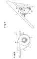
Fig. 1 in einer anderen Seitenansicht, dargestellt in einer Anfangsposition des Kugelstangenlagerkopfes zu dessen Festlegung in der Ruhelage durch Einrücken einer Formschlussverbindung der Kugelstange; - Fig. 8
- die Anhängekupplung nach
Fig. 7 , in einer in der Zeichnungsebene nach links gedrehten Vorderansicht in Pfeilrichtung Y gesehen; - Fig. 9
- eine Darstellung wie gemäß
Fig. 7 , in einer Zwischenposition des Kugelstangenlagerkopfes; - Fig.10
- die Zwischenposition nach
Fig. 9 , in einer Darstellung wie gemäßFig. 8 , - Fig:11
- eine Darstellung wie gemäß
Fig. 7 , in der Endposition des Kugelstangenlagerkopfes; und - Fig.12
- die Endposition nach
Fig. 11 , in einer Darstellung wie gemäßFig. 8 . - Von einer als solche hinlänglich bekannten Anhängekupplung 1 sind in den Figuren der Einfachheit halber lediglich die für die Drehendlagenpositionierung einer an ihrem freien Ende eine Kupplungskugel tragenden Kugelstange erforderlichen Bauteile dargestellt. Diese Bauteile sind ein im Uhrzeigersinn und in Gegenrichtung verschwenkbarer Kugelstangenlagerkopf 2 und ein Anbauflansch 3, über den der Kugelstangenlagerkopf 2 samt Kugelstange an einem ein- oder mehrteiligen Querträger eines Fahrzeugs befestigt ist, sowie ein Verbindungsblech 4 zu dem vorgenannten Querträger der Anhängekupplung 1. Die nach dem axialen Einrücken des Kugelstangenlagerkopfes 2 die jeweilige Drehendlage (Betriebs- oder Ruhestellung) sichernde Formschlussverbindung 5 besteht im Ausführungsbeispiel aus in dem Kugelstangenlagerkopf 2 angeordneten Kugeln 6 und diesen in dem gegenüberliegenden Anbauflansch 3 zugeordneten, nicht gezeigten Kugelkalotten, in die die Kugeln 6 eingreifen und den Kugelstangenlagerkopf 2 bzw. die Kugelstange damit drehfest festlegen.
- Der kegelige Kugelstangenlagerkopf 2 ist hier mit Anschlagmitteln 7 in Form von zwei über seinen größten Durchmesser herausragenden, d.h. radial vorstehenden, im Abstand voneinander angeordneten Bolzen 8a und 8b versehen. Den Bolzen 8a, 8b sind beim Verschwenken des Kugelstangenlagerkopfes 2 in ihrer Bewegungsbahn liegende Gegenanschläge 9 bzw. 10 zugeordnet, und zwar dem Bolzen 8a der die Drehendlage der Betriebsstellung der Anhängekupplung 1 bzw. des Kugelstangenlagerkopfes 2 definierende, am Anbauflansch 3 befestigte Gegenanschlag 9, sowie dem Bolzen 8b der an dem Verbindungsblech 4 ausgebildete, die Drehendlage zur Ruhestellung der Anhängekupplung 1 bzw. des Kugelstangenlagerkopfes 2 definierende Gegenanschlag 10.
- Sowohl der Gegenanschlag 9 als auch der Gegenanschlag 10 sind mit einer Einrückkontur 11 a bzw. 11 b und auch einer Anschlagkontur 12a bzw. 12b ausgebildet (vgl. die
Fig. 1 und7 ). Beim Auftreffen des Bolzens 8a bzw. 8b auf die Einrückkontur 11 a bzw. 11b der Gegenanschläge 9 bzw. 10 wird dem Kugelstangenlagerkopf 2 aufgrund der Formgebung der Einrückkonturen 11a, 11b eine axiale Bewegungskomponente auferlegt, die das Einrasten der Kugeln 6 in die Kugelkalotten der Formschlussverbindung 5 bewirkt. Diese axiale Einrück- bzw. Bewegungskomponente wird exakt in der jeweiligen Drehendlage dann beendet und eine weitere Verschwenkung des Kugelstangenlagenkopfes 2 ausgeschlossen, wenn die Bolzen 8a bzw. 8b auf die Anschlagkonturen 12a bzw. 12b der Gegenanschläge 9 bzw. 10 aufgetroffen sind. - Den ebenso wie die
Fig. 7 bis 12 aufeinanderfolgende Betriebsphasen darstellendenFig. 1 bis 6 läßt sich die Funktion des Gegenanschlags 9 im Zusammenwirken mit dem Bolzen 8a als Drehendanschlag und Einrückhilfe zur Verriegelung der Anhängekupplung 1 in der Betriebsstellung des Kugelstangenlagerkopfes 2 mit Kugelstange und denFig. 7 bis 12 die gleiche Funktion im Zusammenwirken von Bolzen 8b und Gegenanschlag 10 zur Festlegung der Ruhestellung der Anhängekupplung 1 bzw. des Kugelstangenlagerkopfes 3 mit Kugelstange entnehmen. - Sobald der nach
Fig. 1 von dem Gegenanschlag 9 noch entfernte Bolzen 8a durch weiteres Verschwenken des Kugelstangenlagerkopfes 2 auf die hier an einem hakenartigen Kopfstück des Gegenanschlags 9 ausgebildete Einrückkontur 11a aufläuft (vgl.Fig. 3 ), wird der Kugelstangenlagerkopf 2 mit den Kugeln 6 allmählich zunehmend weiter in Richtung auf die Kugelkalotten des Anbauflansches 3 eingerückt, bis beim Auftreffen des Bolzens 8a auf die Anschlagkontur 12a (vgl.Fig. 5 ) die Endlage erreicht ist, in der die Kugeln 6 völlig in die Kugelkalotten eingetaucht sind und die somit geschlossene Formschlussverbindung 5 den Kugelstangenlagerkopf 2 in dieser Endposition drehfest festlegt. - Der Gleiche Ablauf mit denselben Wirkungen bzw. Funktionen wie zuvor beschrieben stellt sich beim Verschwenken des Kugelstangenkopfes 2 in Gegenrichtung zur Ruhestellungs-Positionierung ein. Sobald der nach
Fig. 7 von dem Gegenanschlag 10 noch entfernte Bolzen 8b durch weiteres Verschwenken des Kugelstangenlagerkopfes 2 auf die sogleich an dem Verbindungsblech 4 ausgebildete Einrückkontur 11 b des Gegenanschlags 10 aufläuft (vgl.Fig. 9 ), wird der Kugelstangenlagerkopf 2 mit den Kugeln 6 allmählich zunehmend weiter in Richtung auf die Kugelkalotten des Anbauflansches 3 eingerückt, bis beim Auftreffen des Bolzens 8b auf die Anschlagkontur 12b (vgl.Fig. 11 ) die Endlage erreicht ist, in der die Kugeln 6 völlig in die Kugelkalotten eingetaucht sind und die somit geschlossene Formschlussverbindung 5 den Kugelstangenlagerkopf 2 in dieser Endposition drehfest festlegt.
Claims (4)
- Anhängekupplung (1) für Kraftfahrzeuge, umfassend eine fahrzeugfest angeordnete, schwenkbar sowie axial verschieblich gelagerte Kugelstange, die an ihrem freien Ende eine Kupplungskugel trägt und sowohl in ihrer Ruhestellung als auch in ihrer Betriebsstellung über in Eingriff bringbare Formschlußkonturen (6) einerseits eines Kugelstangenlagerkopfes (2) und andererseits eines diesem gegenüber liegenden Bauteiles (3) drehfest festlegbar ist, wobei der Kugelstangenlagerkopf (2) mit Anschlagmitteln (7; 8a, 8b) ausgebildet ist, denen in seiner Schwenkbahn liegende Gegenanschläge (9; 10) zugeordnet sind, die in der Betriebsstellung und in der Ruhestellung der Kugelstange die Schwenkbewegung des Kugelstangenlagerkopfes (2) begrenzen
dadurch gekennzeichnet,
daß die Gegenanschläge (9; 10) gleichzeitig zum axialen Einrücken des Kugelstangenlagerkopfes (2) in die Formschlussverbindung (5) der Formschlusskonturen (6) ausgebildet sind. - Anhängekupplung nach Anspruch 1,
dadurch gekennzeichnet,
daß die Gegenanschläge (9; 10) mit einer den Anschlagmitteln (7; 8a, 8b) beim Auftreffen eine axiale Bewegungskomponente auferlegenden Einrückkontur (11a; 11 b) ausgebildet sind, die in eine die Bewegungen beendende Anschlagkontur (12a; 12b) übergeht. - Anhängekupplung nach Anspruch 1 oder 2,
gekennzeichnet durch
zwei im Abstand voneinander angeordnete, über den Kugelstangenlagerkopf (2) radial herausragende Bolzen (8a, 8b) als Anschlagmittel (7). - Anhängekupplung nach einem der Ansprüche 1 bis 3,
dadurch gekennzeichnet,
daß die Gegenanschläge (9; 10) an Bauteilen (3; 4) eines am Fahrzeug montierten Anhängerkupplungs-Querträgers angeordnet sind.
Applications Claiming Priority (1)
| Application Number | Priority Date | Filing Date | Title |
|---|---|---|---|
| DE202004010806U DE202004010806U1 (de) | 2004-07-10 | 2004-07-10 | Anhängerkupplung für Kraftfahrzeuge |
Publications (3)
| Publication Number | Publication Date |
|---|---|
| EP1614557A2 EP1614557A2 (de) | 2006-01-11 |
| EP1614557A3 EP1614557A3 (de) | 2006-06-21 |
| EP1614557B1 true EP1614557B1 (de) | 2011-02-23 |
Family
ID=33395347
Family Applications (1)
| Application Number | Title | Priority Date | Filing Date |
|---|---|---|---|
| EP05014641A Expired - Lifetime EP1614557B1 (de) | 2004-07-10 | 2005-07-06 | Anhängekupplung für Kraftfahrzeuge |
Country Status (3)
| Country | Link |
|---|---|
| EP (1) | EP1614557B1 (de) |
| AT (1) | ATE499225T1 (de) |
| DE (2) | DE202004010806U1 (de) |
Families Citing this family (1)
| Publication number | Priority date | Publication date | Assignee | Title |
|---|---|---|---|---|
| WO2008089145A2 (en) | 2007-01-15 | 2008-07-24 | Phd, Inc. | Armover clamp assembly |
Family Cites Families (7)
| Publication number | Priority date | Publication date | Assignee | Title |
|---|---|---|---|---|
| DE9408478U1 (de) | 1994-05-21 | 1994-09-08 | Westfalia-Werke Knöbel GmbH & Co., 33378 Rheda-Wiedenbrück | Drehverriegelung für einen Handradantrieb von geradlinig geführten Hubzahnstangen |
| DE19612962A1 (de) * | 1996-04-01 | 1997-10-02 | Oris Fahrzeugteile Riehle H | Anhängekupplung |
| DE19859961C2 (de) | 1998-12-29 | 2003-07-03 | Westfalia Automotive Gmbh & Co | Anhängerkupplung mit einem schwenkbaren Kugelhals |
| DE10017013A1 (de) | 2000-04-05 | 2001-10-18 | Oris Fahrzeugteile Riehle H | Anhängekupplung |
| DE10252722B3 (de) | 2002-11-13 | 2004-02-19 | Westfalia-Automotive Gmbh & Co. Kg | Anhängekupplung für Kraftfahrzeuge |
| DE10329622A1 (de) * | 2003-06-26 | 2005-01-20 | Oris Fahrzeugteile Hans Riehle Gmbh | Anhängekupplung |
| DE10347816B4 (de) * | 2003-10-10 | 2014-06-05 | Westfalia-Automotive Gmbh | Anhängekupplung mit lastfreier Drehlagereinrichtung |
-
2004
- 2004-07-10 DE DE202004010806U patent/DE202004010806U1/de not_active Expired - Lifetime
-
2005
- 2005-07-06 DE DE502005010990T patent/DE502005010990D1/de not_active Expired - Lifetime
- 2005-07-06 EP EP05014641A patent/EP1614557B1/de not_active Expired - Lifetime
- 2005-07-06 AT AT05014641T patent/ATE499225T1/de active
Also Published As
| Publication number | Publication date |
|---|---|
| DE502005010990D1 (de) | 2011-04-07 |
| EP1614557A2 (de) | 2006-01-11 |
| ATE499225T1 (de) | 2011-03-15 |
| EP1614557A3 (de) | 2006-06-21 |
| DE202004010806U1 (de) | 2004-10-21 |
Similar Documents
| Publication | Publication Date | Title |
|---|---|---|
| EP2504219B2 (de) | Lenksäule für ein kraftfahrzeug | |
| DE102013104958B3 (de) | Energieabsorptionsvorrichtung für eine Lenksäule | |
| DE102011103225B4 (de) | Fahrzeugsitz | |
| DE102013109630B4 (de) | Fahrzeug mit einer Abweisvorrichtung sowie Abweisvorrichtung | |
| DE102011101284B4 (de) | Verriegelungsvorrichtung | |
| WO2016177635A1 (de) | Schliessbügelanordnung zum wahlweisen rückhalten oder rotatorischen freigeben einer frontklappe eines kraftfahrzeuges | |
| EP1428697B1 (de) | Anhängekupplung für Kraftfahrzeuge | |
| EP3394371A1 (de) | Sicherheitsvorrichtung für ein kraftfahrzeug mit einer drehfalle und einer vorraststellung und einer hauptraststellung | |
| DE102017107034A1 (de) | Lenksäule mit Energieabsorptionsvorrichtung | |
| WO2014019933A1 (de) | Verstellbarer fahrzeugsitz | |
| EP1637364B1 (de) | Anhängerkupplung | |
| EP1535765A1 (de) | Anhängerkupplung | |
| DE102015221563A1 (de) | Höheneinstellbarer fahrzeugsitz mit crashsperreneinheit | |
| EP1650059B1 (de) | Anhängekupplung für Kraftfahrzeuge | |
| EP1491369B1 (de) | Anhängekupplung | |
| DE1801251A1 (de) | Lenkstock fuer Kraftfahrzeuge | |
| DE102006010801A1 (de) | Anstellvorrichtung und Anstellverfahren für ein Fahrzeugkarosserieteil | |
| DE102007028770B4 (de) | Lenksäulenanordnung für ein Kraftfahrzeug | |
| EP2755864B1 (de) | Dachlastenträger für kraftfahrzeuge | |
| DE102006004531B3 (de) | Rückenlehne für einen Fahrzeugsitz | |
| EP1614557A2 (de) | Anhängekupplung für Kraftfahrzeuge | |
| DE3223719A1 (de) | Anhaengerkupplung fuer fahrzeuge | |
| EP1562799B1 (de) | Einrichtung zum reversieren einer zum unfallschutz sensorgesteuert aktiv aufgestellten fronthaube eines kraftfahrzeuges | |
| DE10340347B4 (de) | Anhängerkupplung für Kraftfahrzeuge | |
| EP2671739A2 (de) | Betätigungssystem für eine Anhängekupplung eines Kraftfahrzeugs |
Legal Events
| Date | Code | Title | Description |
|---|---|---|---|
| PUAI | Public reference made under article 153(3) epc to a published international application that has entered the european phase |
Free format text: ORIGINAL CODE: 0009012 |
|
| AK | Designated contracting states |
Kind code of ref document: A2 Designated state(s): AT BE BG CH CY CZ DE DK EE ES FI FR GB GR HU IE IS IT LI LT LU LV MC NL PL PT RO SE SI SK TR |
|
| AX | Request for extension of the european patent |
Extension state: AL BA HR MK YU |
|
| PUAL | Search report despatched |
Free format text: ORIGINAL CODE: 0009013 |
|
| AK | Designated contracting states |
Kind code of ref document: A3 Designated state(s): AT BE BG CH CY CZ DE DK EE ES FI FR GB GR HU IE IS IT LI LT LU LV MC NL PL PT RO SE SI SK TR |
|
| AX | Request for extension of the european patent |
Extension state: AL BA HR MK YU |
|
| RAP1 | Party data changed (applicant data changed or rights of an application transferred) |
Owner name: WESTFALIA - AUTOMOTIVE GMBH |
|
| 17P | Request for examination filed |
Effective date: 20061205 |
|
| 17Q | First examination report despatched |
Effective date: 20070116 |
|
| AKX | Designation fees paid |
Designated state(s): AT BE BG CH CY CZ DE DK EE ES FI FR GB GR HU IE IS IT LI LT LU LV MC NL PL PT RO SE SI SK TR |
|
| GRAP | Despatch of communication of intention to grant a patent |
Free format text: ORIGINAL CODE: EPIDOSNIGR1 |
|
| GRAS | Grant fee paid |
Free format text: ORIGINAL CODE: EPIDOSNIGR3 |
|
| GRAA | (expected) grant |
Free format text: ORIGINAL CODE: 0009210 |
|
| AK | Designated contracting states |
Kind code of ref document: B1 Designated state(s): AT BE BG CH CY CZ DE DK EE ES FI FR GB GR HU IE IS IT LI LT LU LV MC NL PL PT RO SE SI SK TR |
|
| REG | Reference to a national code |
Ref country code: GB Ref legal event code: FG4D Free format text: NOT ENGLISH |
|
| REG | Reference to a national code |
Ref country code: CH Ref legal event code: EP |
|
| REG | Reference to a national code |
Ref country code: IE Ref legal event code: FG4D Free format text: LANGUAGE OF EP DOCUMENT: GERMAN |
|
| REF | Corresponds to: |
Ref document number: 502005010990 Country of ref document: DE Date of ref document: 20110407 Kind code of ref document: P |
|
| REG | Reference to a national code |
Ref country code: DE Ref legal event code: R096 Ref document number: 502005010990 Country of ref document: DE Effective date: 20110407 |
|
| REG | Reference to a national code |
Ref country code: NL Ref legal event code: VDEP Effective date: 20110223 |
|
| LTIE | Lt: invalidation of european patent or patent extension |
Effective date: 20110223 |
|
| PG25 | Lapsed in a contracting state [announced via postgrant information from national office to epo] |
Ref country code: PT Free format text: LAPSE BECAUSE OF FAILURE TO SUBMIT A TRANSLATION OF THE DESCRIPTION OR TO PAY THE FEE WITHIN THE PRESCRIBED TIME-LIMIT Effective date: 20110623 Ref country code: ES Free format text: LAPSE BECAUSE OF FAILURE TO SUBMIT A TRANSLATION OF THE DESCRIPTION OR TO PAY THE FEE WITHIN THE PRESCRIBED TIME-LIMIT Effective date: 20110603 Ref country code: SE Free format text: LAPSE BECAUSE OF FAILURE TO SUBMIT A TRANSLATION OF THE DESCRIPTION OR TO PAY THE FEE WITHIN THE PRESCRIBED TIME-LIMIT Effective date: 20110223 Ref country code: GR Free format text: LAPSE BECAUSE OF FAILURE TO SUBMIT A TRANSLATION OF THE DESCRIPTION OR TO PAY THE FEE WITHIN THE PRESCRIBED TIME-LIMIT Effective date: 20110524 Ref country code: LT Free format text: LAPSE BECAUSE OF FAILURE TO SUBMIT A TRANSLATION OF THE DESCRIPTION OR TO PAY THE FEE WITHIN THE PRESCRIBED TIME-LIMIT Effective date: 20110223 Ref country code: LV Free format text: LAPSE BECAUSE OF FAILURE TO SUBMIT A TRANSLATION OF THE DESCRIPTION OR TO PAY THE FEE WITHIN THE PRESCRIBED TIME-LIMIT Effective date: 20110223 |
|
| PG25 | Lapsed in a contracting state [announced via postgrant information from national office to epo] |
Ref country code: FI Free format text: LAPSE BECAUSE OF FAILURE TO SUBMIT A TRANSLATION OF THE DESCRIPTION OR TO PAY THE FEE WITHIN THE PRESCRIBED TIME-LIMIT Effective date: 20110223 Ref country code: SI Free format text: LAPSE BECAUSE OF FAILURE TO SUBMIT A TRANSLATION OF THE DESCRIPTION OR TO PAY THE FEE WITHIN THE PRESCRIBED TIME-LIMIT Effective date: 20110223 Ref country code: NL Free format text: LAPSE BECAUSE OF FAILURE TO SUBMIT A TRANSLATION OF THE DESCRIPTION OR TO PAY THE FEE WITHIN THE PRESCRIBED TIME-LIMIT Effective date: 20110223 Ref country code: BG Free format text: LAPSE BECAUSE OF FAILURE TO SUBMIT A TRANSLATION OF THE DESCRIPTION OR TO PAY THE FEE WITHIN THE PRESCRIBED TIME-LIMIT Effective date: 20110523 Ref country code: CY Free format text: LAPSE BECAUSE OF FAILURE TO SUBMIT A TRANSLATION OF THE DESCRIPTION OR TO PAY THE FEE WITHIN THE PRESCRIBED TIME-LIMIT Effective date: 20110223 |
|
| REG | Reference to a national code |
Ref country code: IE Ref legal event code: FD4D |
|
| PG25 | Lapsed in a contracting state [announced via postgrant information from national office to epo] |
Ref country code: IE Free format text: LAPSE BECAUSE OF FAILURE TO SUBMIT A TRANSLATION OF THE DESCRIPTION OR TO PAY THE FEE WITHIN THE PRESCRIBED TIME-LIMIT Effective date: 20110223 Ref country code: EE Free format text: LAPSE BECAUSE OF FAILURE TO SUBMIT A TRANSLATION OF THE DESCRIPTION OR TO PAY THE FEE WITHIN THE PRESCRIBED TIME-LIMIT Effective date: 20110223 Ref country code: DK Free format text: LAPSE BECAUSE OF FAILURE TO SUBMIT A TRANSLATION OF THE DESCRIPTION OR TO PAY THE FEE WITHIN THE PRESCRIBED TIME-LIMIT Effective date: 20110223 |
|
| PG25 | Lapsed in a contracting state [announced via postgrant information from national office to epo] |
Ref country code: CZ Free format text: LAPSE BECAUSE OF FAILURE TO SUBMIT A TRANSLATION OF THE DESCRIPTION OR TO PAY THE FEE WITHIN THE PRESCRIBED TIME-LIMIT Effective date: 20110223 Ref country code: RO Free format text: LAPSE BECAUSE OF FAILURE TO SUBMIT A TRANSLATION OF THE DESCRIPTION OR TO PAY THE FEE WITHIN THE PRESCRIBED TIME-LIMIT Effective date: 20110223 Ref country code: SK Free format text: LAPSE BECAUSE OF FAILURE TO SUBMIT A TRANSLATION OF THE DESCRIPTION OR TO PAY THE FEE WITHIN THE PRESCRIBED TIME-LIMIT Effective date: 20110223 |
|
| PLBE | No opposition filed within time limit |
Free format text: ORIGINAL CODE: 0009261 |
|
| STAA | Information on the status of an ep patent application or granted ep patent |
Free format text: STATUS: NO OPPOSITION FILED WITHIN TIME LIMIT |
|
| BERE | Be: lapsed |
Owner name: WESTFALIA - AUTOMOTIVE G.M.B.H. Effective date: 20110731 |
|
| 26N | No opposition filed |
Effective date: 20111124 |
|
| PG25 | Lapsed in a contracting state [announced via postgrant information from national office to epo] |
Ref country code: PL Free format text: LAPSE BECAUSE OF FAILURE TO SUBMIT A TRANSLATION OF THE DESCRIPTION OR TO PAY THE FEE WITHIN THE PRESCRIBED TIME-LIMIT Effective date: 20110223 Ref country code: MC Free format text: LAPSE BECAUSE OF NON-PAYMENT OF DUE FEES Effective date: 20110731 |
|
| REG | Reference to a national code |
Ref country code: CH Ref legal event code: PL |
|
| REG | Reference to a national code |
Ref country code: DE Ref legal event code: R097 Ref document number: 502005010990 Country of ref document: DE Effective date: 20111124 |
|
| GBPC | Gb: european patent ceased through non-payment of renewal fee |
Effective date: 20110706 |
|
| PG25 | Lapsed in a contracting state [announced via postgrant information from national office to epo] |
Ref country code: BE Free format text: LAPSE BECAUSE OF NON-PAYMENT OF DUE FEES Effective date: 20110731 Ref country code: CH Free format text: LAPSE BECAUSE OF NON-PAYMENT OF DUE FEES Effective date: 20110731 Ref country code: LI Free format text: LAPSE BECAUSE OF NON-PAYMENT OF DUE FEES Effective date: 20110731 |
|
| PG25 | Lapsed in a contracting state [announced via postgrant information from national office to epo] |
Ref country code: IT Free format text: LAPSE BECAUSE OF FAILURE TO SUBMIT A TRANSLATION OF THE DESCRIPTION OR TO PAY THE FEE WITHIN THE PRESCRIBED TIME-LIMIT Effective date: 20110223 |
|
| PG25 | Lapsed in a contracting state [announced via postgrant information from national office to epo] |
Ref country code: GB Free format text: LAPSE BECAUSE OF NON-PAYMENT OF DUE FEES Effective date: 20110706 |
|
| REG | Reference to a national code |
Ref country code: AT Ref legal event code: MM01 Ref document number: 499225 Country of ref document: AT Kind code of ref document: T Effective date: 20110706 |
|
| PG25 | Lapsed in a contracting state [announced via postgrant information from national office to epo] |
Ref country code: AT Free format text: LAPSE BECAUSE OF NON-PAYMENT OF DUE FEES Effective date: 20110706 |
|
| PG25 | Lapsed in a contracting state [announced via postgrant information from national office to epo] |
Ref country code: LU Free format text: LAPSE BECAUSE OF NON-PAYMENT OF DUE FEES Effective date: 20110706 |
|
| PG25 | Lapsed in a contracting state [announced via postgrant information from national office to epo] |
Ref country code: IS Free format text: LAPSE BECAUSE OF FAILURE TO SUBMIT A TRANSLATION OF THE DESCRIPTION OR TO PAY THE FEE WITHIN THE PRESCRIBED TIME-LIMIT Effective date: 20110223 |
|
| PG25 | Lapsed in a contracting state [announced via postgrant information from national office to epo] |
Ref country code: TR Free format text: LAPSE BECAUSE OF FAILURE TO SUBMIT A TRANSLATION OF THE DESCRIPTION OR TO PAY THE FEE WITHIN THE PRESCRIBED TIME-LIMIT Effective date: 20110223 |
|
| PG25 | Lapsed in a contracting state [announced via postgrant information from national office to epo] |
Ref country code: HU Free format text: LAPSE BECAUSE OF FAILURE TO SUBMIT A TRANSLATION OF THE DESCRIPTION OR TO PAY THE FEE WITHIN THE PRESCRIBED TIME-LIMIT Effective date: 20110223 |
|
| REG | Reference to a national code |
Ref country code: FR Ref legal event code: PLFP Year of fee payment: 12 |
|
| REG | Reference to a national code |
Ref country code: FR Ref legal event code: PLFP Year of fee payment: 13 |
|
| REG | Reference to a national code |
Ref country code: FR Ref legal event code: PLFP Year of fee payment: 14 |
|
| PGFP | Annual fee paid to national office [announced via postgrant information from national office to epo] |
Ref country code: FR Payment date: 20220726 Year of fee payment: 18 |
|
| PG25 | Lapsed in a contracting state [announced via postgrant information from national office to epo] |
Ref country code: FR Free format text: LAPSE BECAUSE OF NON-PAYMENT OF DUE FEES Effective date: 20230731 |
|
| PGFP | Annual fee paid to national office [announced via postgrant information from national office to epo] |
Ref country code: DE Payment date: 20240603 Year of fee payment: 20 |
|
| REG | Reference to a national code |
Ref country code: DE Ref legal event code: R071 Ref document number: 502005010990 Country of ref document: DE |