EP1614310B1 - Arrangement comprising a mobile telephone and an auxiliary memory - Google Patents
Arrangement comprising a mobile telephone and an auxiliary memory Download PDFInfo
- Publication number
- EP1614310B1 EP1614310B1 EP04724499A EP04724499A EP1614310B1 EP 1614310 B1 EP1614310 B1 EP 1614310B1 EP 04724499 A EP04724499 A EP 04724499A EP 04724499 A EP04724499 A EP 04724499A EP 1614310 B1 EP1614310 B1 EP 1614310B1
- Authority
- EP
- European Patent Office
- Prior art keywords
- memory
- data
- signal
- auxiliary memory
- initialisation
- Prior art date
- Legal status (The legal status is an assumption and is not a legal conclusion. Google has not performed a legal analysis and makes no representation as to the accuracy of the status listed.)
- Expired - Lifetime
Links
- 230000015654 memory Effects 0.000 title claims abstract description 164
- 238000001514 detection method Methods 0.000 claims abstract description 5
- 230000004913 activation Effects 0.000 claims description 21
- 238000006386 neutralization reaction Methods 0.000 claims description 6
- 238000012795 verification Methods 0.000 claims description 3
- 238000004891 communication Methods 0.000 description 9
- 230000006870 function Effects 0.000 description 4
- 230000008878 coupling Effects 0.000 description 2
- 238000010168 coupling process Methods 0.000 description 2
- 238000005859 coupling reaction Methods 0.000 description 2
- 230000005284 excitation Effects 0.000 description 1
- 238000000034 method Methods 0.000 description 1
- 210000000056 organ Anatomy 0.000 description 1
- 230000005236 sound signal Effects 0.000 description 1
Images
Classifications
-
- H—ELECTRICITY
- H04—ELECTRIC COMMUNICATION TECHNIQUE
- H04W—WIRELESS COMMUNICATION NETWORKS
- H04W88/00—Devices specially adapted for wireless communication networks, e.g. terminals, base stations or access point devices
- H04W88/02—Terminal devices
-
- H—ELECTRICITY
- H04—ELECTRIC COMMUNICATION TECHNIQUE
- H04M—TELEPHONIC COMMUNICATION
- H04M1/00—Substation equipment, e.g. for use by subscribers
- H04M1/72—Mobile telephones; Cordless telephones, i.e. devices for establishing wireless links to base stations without route selection
- H04M1/724—User interfaces specially adapted for cordless or mobile telephones
- H04M1/72403—User interfaces specially adapted for cordless or mobile telephones with means for local support of applications that increase the functionality
- H04M1/72409—User interfaces specially adapted for cordless or mobile telephones with means for local support of applications that increase the functionality by interfacing with external accessories
Definitions
- the present invention relates to an assembly comprising a mobile phone powered by an autonomous source of energy, an auxiliary memory and a charger arranged to charge the energy source, which telephone is provided with a memory arranged to store data of the same. operator and data introduced by a phone holder, which memory and auxiliary memory are each equipped with a reading and writing device to allow reading and writing data in the respective memory.
- the auxiliary memory is associated with the charger, which charger is provided with initialization means connected to said reading and writing devices, which initialization means are arranged to detect a loading of the energy source and produce a signal of initialization after detection of such loading,
- auxiliary memory is housed in a housing which also comprises a connector for connecting the mobile phone using its connection pins.
- the auxiliary memory is used to copy the data stored in the phone's memory.
- the holder of the phone has a copy of the data stored in the memory of his phone, which allows him to recover this data in case for any reason he would no longer be in possession of the phone and / or data stored in the phone's memory.
- a disadvantage of the known set is that it is the holder himself who must take the initiative to connect his mobile phone on the housing to allow copying of data in the auxiliary memory. Not only can the holder forget to start copying by plugging the phone into the case, which means that the contents of the auxiliary memory are not updated regularly, but the holder is also obliged to bring him the case, for example when he goes on a trip, if he wishes a regular update of the auxiliary memory.
- the object of the invention is to provide an assembly comprising a mobile phone and an auxiliary memory where the loading of the auxiliary memory is done automatically and regularly.
- an assembly according to the invention is characterized in that the initialization means are arranged to activate the memory reader and the auxiliary memory write device under control of the initialization signal so that read the data from the memory and write in the auxiliary memory at least those data of the memory, which would not yet be recorded in the auxiliary memory.
- the power source must regularly be loaded using the charger, the fact of detecting a load and produce an initialization signal after detection of such a load, will allow to regularly produce an initialization signal. Since it is the initialization signal that activates both the reading device of the telephone memory and the writing device of the auxiliary memory, reading the data stored in the memory and writing these read data. will be done regularly and automatically, thus allowing an update regular auxiliary memory.
- the auxiliary memory and the initialization means are associated with the charger, the holder will take them with him when he carries his charger thus no longer requiring a separate housing.
- a first preferred embodiment of an assembly according to the invention is characterized in that an identification code is stored in the memories and in that the initialization means comprise a verification element arranged to compare, under control. of the initialization signal, the codes stored in the memory and the auxiliary memory respectively the first and second memory and to produce a neutralization signal in case of non-correspondence of the identification codes compared with each other, which activation of the organ reading and writing is neutralized under the control of the neutralization signal.
- This identification code is for example the PIN or PUK code assigned to the SIM card.
- the presence of the verification element makes it possible to check whether the memories concerned have the same identification code. If this is not the case, it means that the auxiliary memory or the first memory are not those where the copy is normally stored. Copying the data is therefore meaningless and the override signal will be generated to disable activation of the read and write device and thereby prevent copying of the data.
- a second preferred embodiment of an assembly according to the invention is characterized in that the initialization means are arranged to activate the reading device of the auxiliary memory respectively of the first memory under control of the initialization signal so that to read the data of these memories, which initialization means comprise a comparator arranged to receive the data read in the respective memories, after activation of the reading members and to compare with one another the data stored in the first memory and the second memory respectively. memory and the auxiliary memory and to locate on the basis of the comparison the data of the second memory respectively of the memory, which would not be stored in the first memory respectively the auxiliary memory and store in the first memory respectively the auxiliary memory that the data identified. Comparing the data thus makes it possible to store in the auxiliary memory or the first memory only those data that were not yet stored therein.
- a third preferred embodiment of an assembly according to the invention is characterized in that the initialization means are provided with a counter having an input for receiving the initialization signal, which counter is arranged to increment a readiness rate. counting after receiving the initialization signal and for producing a counting signal when the counting rate has reached a predetermined threshold and a stop signal when said counting rate has not reached said threshold, which initialization means are arranged to neutralize said activation of the reading elements and write under control of the stop signal and initialize the count rate under control of the count signal.
- This embodiment is advantageous for mobile phone owners who modify only occasionally the contents of the phone memory. By performing the write operation in the auxiliary memory or the first memory only after having reached a predetermined number of loading, the number of data transfers is limited.
- the initialization means are provided with a transmitter arranged to transmit a message indicating a write in the auxiliary memory or the first memory respectively when data is written therein. The user is thus notified that the write operation is in progress.
- a fourth preferred embodiment of an assembly according to the invention is characterized in that the initialization means comprise an activation key which can be activated by a user, which activation key is arranged to produce a signal of activation after being controlled, which write members of the memory or of the second memory and which auxiliary memory reading members or the first memory are activatable under control of the activation signal to enable writing to the memory or the second memory of the data read from the auxiliary memory or the first memory.
- the activation of said key thus makes it possible to transfer the data saved in the auxiliary memory or the first memory to that of the telephone and thus recover the saved data.
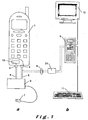
- the set illustrated in the figure 1 a comprises a mobile telephone 1 provided with a first connection pin 2 forming an input supply of an electric current for charging the autonomous power source 13, generally formed by a rechargeable battery.
- the first pin 2 is connected using a wire 4 to a charger 6 arranged to charge the power source 13.
- the charger also has a wire with a plug 7 for connecting the charger to a power grid .
- a second pin 3 forms a data exchange interface.
- the set illustrated at figure 1b is different from that illustrated in figure 1 a in that instead of the charger there is a computer 9 and a communication module 21 arranged to establish a data communication between the phone and the computer.
- the latter is preferably equipped with a keyboard 11 and a display screen 10.
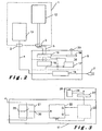
- the charger 6 is generally provided with a transformer-converter 18, as illustrated in FIG. figure 2 , which transformer-converter is arranged to transform the alternating current supplied by the network into a low voltage direct current. The latter is then supplied to the power source 13 in order to charge it.
- a transformer-converter 18 as illustrated in FIG. figure 2 , which transformer-converter is arranged to transform the alternating current supplied by the network into a low voltage direct current. The latter is then supplied to the power source 13 in order to charge it.
- the charger is provided with initialization means 14. These can be connected to the memory 12 of the phone 1 by means of the link 5 which can be connected to the second pin 3.
- the charger 6 is also associated with a auxiliary memory 16.
- the initialization means and the auxiliary memory 16 are incorporated in the same housing as that which comprises the transformer-converter of the charger. Of course separate housing can also be considered for these different components.
- the memory 12 of the telephone is preferably formed by the SIM card and / or by a memory of the telephone arranged to store operator data and data entered by the telephone holder.
- the data is for example the PIN and PUK code, telephone numbers introduced by the holder, images to be displayed on the telephone screen or other data specific to the holder and that he wishes to memorize.
- the auxiliary memory 16 is also arranged to store the same data as those stored in the memory 12 of the phone. In order to read and write data in the memories 12 and 16, the latter are each equipped with a reading member and a writing member (not shown in the drawings).
- the initialization means are arranged to detect a loading of the energy source 13 and produce an initialization signal after detection of such a load.
- a detector 17 having an input connected to the output of the transformer-converter 18.
- An exemplary embodiment of such a detector is illustrated to the figure 3 .
- the detector comprises a relay 21 whose excitation input is connected to the line 4 leaving the transformer-converter.
- a current input 25 of the relay is connected to a current supply source which may possibly be line 4.
- a current output 26 of the relay is connected to an input A of a flip-flop 22, including a Q output. is connected to an input of a counter 23. It should however be noted that the counter 23 is optional.
- This counter is arranged to count to a predetermined count rate and to be reset or initialized when said count rate has been reached.
- An output of the meter is connected to an interface 15 and to a transmitter 24 arranged to transmit a message, as will be described in more detail below.
- the interface 15 comprises a buffer memory, which may optionally be provided with a data comparator and a management logic unit.
- the interface is located either in the charger housing or in the phone itself. In the latter case, the logical drive can be integrated into the phone's computer.
- the initialization means also comprise an activation key 20, for example a press button connected to an activation signal generator 19.
- the counter If the counter has reached the predetermined threshold it will produce a count signal which will be supplied to a generator 27 arranged to produce an initialization signal. If on the other hand the counter has not reached said threshold a stop signal will be produced which will neutralize the generator 27 and thus the operation of the initialization means.
- the output signal of the flip-flop is directly supplied to the generator 27 and there is no neutralization that occurs.
- the detector for example, using AND or OR logic gates, can be envisaged.
- the use of a counter 23 makes it possible not to have to activate all the operations of the initialization means during each loading of the energy source.
- the generator 27 has produced the initialization signal.
- the latter is then supplied to the interface 15 which will be activated under control of the initialization signal.
- the interface When the interface is not equipped with a comparator, it will erase the contents of the auxiliary memory 16 and activate the reading member of the memory 12 in order to read the data stored therein.
- the read data is temporarily stored in the interface 15 which will also activate the writing device of the auxiliary memory. When this writing device is activated, the writing of the data coming from the memory 12 will be done in the auxiliary memory 16. Thus the data stored in the memory 12 of the telephone will be copied to the auxiliary memory 16.
- the initialization signal will not only activate the reading member of the memory 12 but also that of the memory 16 so as also to read the data stored in this latter memory.
- the comparator will then receive the data read in the two memories and will compare them with each other in order to verify which data is stored in the memory 12 are not yet stored in the auxiliary memory 16.
- the comparator will locate, on the basis of the comparison, the data that would not yet be copied to the auxiliary memory. Only the data thus identified will then be stored in the auxiliary memory. This avoids each time having to empty all of the auxiliary memory 16 and to copy each time all the data from the memory 12 into the auxiliary memory 16.
- the transmitter 24 will issue a message.
- the transmitter receives not only the initialization signal, by its connection with the output of the generator 27, but also at its input 28 the signal which activates the writing device of the auxiliary memory 16. So also long that writing is in progress in the auxiliary memory, the transmitter will send a message. Thus the holder is notified that a write has taken place in the auxiliary memory and therefore it must not disconnect the charger, otherwise the write operation is disturbed by lack of power supply.
- the transmitter may include a siren emitting a sound signal, or may be connected to the phone screen to display a message for example in the form of an icon or a written message. According to another alternative the transmitter comprises a light indicator on the housing.
- the purpose of copying into the auxiliary memory the data in the memory 12 of the phone is of course to be able, if necessary, copy them in the memory 12 for example in case of loss of the phone.
- the user wants to copy the data stored in the auxiliary memory 16 he will activate the activation key 20 to activate the generator 19 which will then produce an activation signal.
- the interface 15, which will receive the activation signal, goes under control of the latter signal, activate the memory reader auxiliary and the writing member of the memory 12 of the phone.
- the data stored in the auxiliary memory 16 will be read and then written in the memory 12.
- the latter will again be provided with the data necessary for its operation.
- the identification code for example the PIN code and / or PUK of the card SIM.
- the identification codes stored in the memories 12 and 16. This comparison will be performed under control of the initialization signal. If the codes of the two memories match, the writing can be done in the auxiliary memory. In the opposite case, the memory reading and writing device will not be activated or neutralized by a neutralization signal produced by the comparator following a negative comparison. Thus it avoids that when the holder charge are phone with a charger that is not his, the contents of the memory of his phone is copied to an auxiliary memory that does not belong to him.
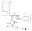
- the figure 4 illustrates the communication module 21 in conjunction with a first memory 30 of the computer 9 and a second memory 12 of the phone.
- the first memory 30 has a function similar to that of the auxiliary memory 16 described in the embodiment which has just been described namely to store a copy of the data stored in the second memory 12 of the phone. Given that the mode of operation of this embodiment is similar to that just described, only the specific differences will be described. Thus the data comparison functions and / or identification codes, the use of a counter, emission of a message are similar and will therefore no longer be described in detail. for this embodiment.
- the interface 15 is located either in the phone or in the computer itself. In the latter case, the logical unit of the interface is preferably integrated in that of the computer.
- the communication module 21 comprises the initialization means which are for example formed by an AND logic gate 31 connected to an initialization signal generator 32 which is connected to it at an interface 15.
- the logic gate in turn receives an input 31-1 a fixed signal of a logic value "1".
- the other input 31-2 of the logic gate receives a call signal from the telephone indicating that communication with the computer is desired.
- the generator 32 is activated, thus producing an initialization signal which is supplied to the interface 15 which will then activate the reading element of the second memory 12 and the write device of the second memory. the first memory as previously described.
- Some mobile phones also have a calendar function. It goes without saying that in the latter case the data of the agenda can also be doubled in the auxiliary memory or the first memory. In this case, it would even be possible to copy only the calendar data in case the calendar does not have the phone function. The copying of the data would then be analogous to the one just described.
Abstract
Description
La présente invention concerne un ensemble comprenant un téléphone mobile alimenté par une source autonome d'énergie, une mémoire auxiliaire et un chargeur agencé pour charger la source d'énergie, lequel téléphone est pourvu d'une mémoire agencée pour y stocker des données de l'opérateur et des données introduites par un titulaire du téléphone, laquelle mémoire et mémoire auxiliaire sont chaque fois équipées d'un organe de lecture et d'écriture pour permettre la lecture et l'écriture de données dans la mémoire respective. La mémoire auxiliaire est associée au chargeur, lequel chargeur est pourvu de moyens d'initialisation reliés auxdits organes de lecture et d'écriture, lesquels moyens d'initialisation sont agencés pour détecter un chargement de la source d'énergie et produire un signal d'initialisation après détection d'un tel chargement,The present invention relates to an assembly comprising a mobile phone powered by an autonomous source of energy, an auxiliary memory and a charger arranged to charge the energy source, which telephone is provided with a memory arranged to store data of the same. operator and data introduced by a phone holder, which memory and auxiliary memory are each equipped with a reading and writing device to allow reading and writing data in the respective memory. The auxiliary memory is associated with the charger, which charger is provided with initialization means connected to said reading and writing devices, which initialization means are arranged to detect a loading of the energy source and produce a signal of initialization after detection of such loading,
Un tel ensemble est connu du brevet
Un tel ensemble est également connu de la demande de brevet japonais n°
Un inconvénient de l'ensemble connu est que c'est le titulaire lui-même qui doit prendre l'initiative de brancher son téléphone mobile sur le boîtier afin de permettre la copie des données dans la mémoire auxiliaire. Non seulement le titulaire risque d'oublier de lancer la copie en branchant le téléphone sur le boîtier, ce qui a comme conséquence que le contenu de la mémoire auxiliaire ne soit pas régulièrement mis à jour, mais le titulaire est également obligé d'emporter avec lui le boîtier, par exemple lorsqu'il part en voyage, s'il désire une mise à jour régulière de la mémoire auxiliaire.A disadvantage of the known set is that it is the holder himself who must take the initiative to connect his mobile phone on the housing to allow copying of data in the auxiliary memory. Not only can the holder forget to start copying by plugging the phone into the case, which means that the contents of the auxiliary memory are not updated regularly, but the holder is also obliged to bring him the case, for example when he goes on a trip, if he wishes a regular update of the auxiliary memory.
L'invention a pour but de réaliser un ensemble comprenant un téléphone portable et une mémoire auxiliaire où le chargement de la mémoire auxiliaire se fait de façon automatique et régulière.The object of the invention is to provide an assembly comprising a mobile phone and an auxiliary memory where the loading of the auxiliary memory is done automatically and regularly.
A cette fin un ensemble suivant l'invention est caractérisé en ce que les moyens d'initialisation sont agencés pour activer l'organe de lecture de la mémoire et l'organe d'écriture de la mémoire auxiliaire sous contrôle du signal d'initialisation afin de lire les données de la mémoire et d'écrire dans la mémoire auxiliaire au moins ces données de la mémoire, qui ne seraient pas encore enregistrées dans la mémoire auxiliaire. Puisque la source d'énergie doit régulièrement être chargée à l'aide du chargeur, le fait de détecter un chargement et de produire un signal d'initialisation après détection d'un tel chargement, va permettre de produire régulièrement un signal d'initialisation. Puisque c'est le signal d'initialisation qui activée tant l'organe de lecture de la mémoire du téléphone que l'organe d'écriture de la mémoire auxiliaire, la lecture des données stockées dans la mémoire et l'écriture de ces données lues se fera régulièrement et automatiquement, permettant ainsi une mise à jour régulière de la mémoire auxiliaire. De plus, puisque la mémoire auxiliaire et les moyens d'initialisation sont associés au chargeur, le titulaire les emportera avec lui lorsqu'il emporte son chargeur ne nécessitant ainsi plus d'emporter un boîtier séparé.For this purpose, an assembly according to the invention is characterized in that the initialization means are arranged to activate the memory reader and the auxiliary memory write device under control of the initialization signal so that read the data from the memory and write in the auxiliary memory at least those data of the memory, which would not yet be recorded in the auxiliary memory. Since the power source must regularly be loaded using the charger, the fact of detecting a load and produce an initialization signal after detection of such a load, will allow to regularly produce an initialization signal. Since it is the initialization signal that activates both the reading device of the telephone memory and the writing device of the auxiliary memory, reading the data stored in the memory and writing these read data. will be done regularly and automatically, thus allowing an update regular auxiliary memory. In addition, since the auxiliary memory and the initialization means are associated with the charger, the holder will take them with him when he carries his charger thus no longer requiring a separate housing.
Certes le brevet
Une première forme de réalisation préférentielle d'un ensemble suivant l'invention est caractérisée en ce qu'un code d'identification est stocké dans les mémoires et en ce que les moyens d'initialisation comportent un élément de vérification agencé pour comparer, sous contrôle du signal d'initialisation, les codes stockés dans la mémoire et la mémoire auxiliaire respectivement la première et seconde mémoire et pour produire un signal de neutralisation en cas de non-correspondance des codes d'identification comparés entre eux, laquelle activation de l'organe de lecture et d'écriture est neutralisée sous contrôle du signal de neutralisation. Ce code d'identification est par exemple le code PIN ou PUK attribué à la carte SIM. La présence de l'élément de vérification permet de vérifier si les mémoires concernées portent bien le même code d'identification. Si tel n'est pas le cas, cela signifie que la mémoire auxiliaire ou la première mémoire ne sont pas celles où la copie est normalement stockée. Copier les données n'a dès lors pas de sens et le signal de neutralisation sera produit afin de neutraliser l'activation de l'organe de lecture et d'écriture et d'empêcher ainsi de copier les données.A first preferred embodiment of an assembly according to the invention is characterized in that an identification code is stored in the memories and in that the initialization means comprise a verification element arranged to compare, under control. of the initialization signal, the codes stored in the memory and the auxiliary memory respectively the first and second memory and to produce a neutralization signal in case of non-correspondence of the identification codes compared with each other, which activation of the organ reading and writing is neutralized under the control of the neutralization signal. This identification code is for example the PIN or PUK code assigned to the SIM card. The presence of the verification element makes it possible to check whether the memories concerned have the same identification code. If this is not the case, it means that the auxiliary memory or the first memory are not those where the copy is normally stored. Copying the data is therefore meaningless and the override signal will be generated to disable activation of the read and write device and thereby prevent copying of the data.
Une deuxième forme de réalisation préférentielle d'un ensemble suivant l'invention est caractérisée en ce que les moyens d'initialisation sont agencés pour activer l'organe de lecture de la mémoire auxiliaire respectivement de la première mémoire sous contrôle du signal d'initialisation afin de lire les données de ces mémoires, lesquels moyens d'initialisation comportent un comparateur agencé pour recevoir les données lues dans les mémoires respectives, après activation des organes de lecture et pour comparer entre elles les données stockées dans la première et la seconde mémoire respectivement la mémoire et la mémoire auxiliaire et pour repérer sur base de la comparaison les données de la seconde mémoire respectivement de la mémoire, qui ne seraient pas stockées dans la première mémoire respectivement la mémoire auxiliaire et stocker dans la première mémoire respectivement la mémoire auxiliaire que les données repérées. La comparaison des données permet ainsi de ne stocker dans la mémoire auxiliaire ou la première mémoire que ces données qui n'y étaient pas encore stockées.A second preferred embodiment of an assembly according to the invention is characterized in that the initialization means are arranged to activate the reading device of the auxiliary memory respectively of the first memory under control of the initialization signal so that to read the data of these memories, which initialization means comprise a comparator arranged to receive the data read in the respective memories, after activation of the reading members and to compare with one another the data stored in the first memory and the second memory respectively. memory and the auxiliary memory and to locate on the basis of the comparison the data of the second memory respectively of the memory, which would not be stored in the first memory respectively the auxiliary memory and store in the first memory respectively the auxiliary memory that the data identified. Comparing the data thus makes it possible to store in the auxiliary memory or the first memory only those data that were not yet stored therein.
Une troisième forme de réalisation préférentielle d'un ensemble suivant l'invention est caractérisée en ce que les moyens d'initialisation sont pourvus d'un compteur ayant une entrée pour recevoir le signal d'initialisation, lequel compteur est agencé pour incrémenter un taux de comptage après réception du signal d'initialisation et pour produire un signal de comptage lorsque le taux de comptage a atteint un seuil prédéterminé et un signal d'arrêt lorsque ce taux de comptage n'a pas atteint ledit seuil, lesquels moyens d'initialisation sont agencés pour neutraliser ladite activation des organes de lecture et d'écriture sous contrôle du signal d'arrêt et initialiser le taux de comptage sous contrôle du signal de comptage. Cette forme de réalisation est avantageuse pour les titulaires de téléphone mobile qui ne modifient qu'occasionnellement le contenu de la mémoire du téléphone. En n'effectuant l'opération d'écriture dans la mémoire auxiliaire ou la première mémoire qu'après avoir atteint un nombre prédéterminé de chargement, le nombre de transferts de données est limité.A third preferred embodiment of an assembly according to the invention is characterized in that the initialization means are provided with a counter having an input for receiving the initialization signal, which counter is arranged to increment a readiness rate. counting after receiving the initialization signal and for producing a counting signal when the counting rate has reached a predetermined threshold and a stop signal when said counting rate has not reached said threshold, which initialization means are arranged to neutralize said activation of the reading elements and write under control of the stop signal and initialize the count rate under control of the count signal. This embodiment is advantageous for mobile phone owners who modify only occasionally the contents of the phone memory. By performing the write operation in the auxiliary memory or the first memory only after having reached a predetermined number of loading, the number of data transfers is limited.
De préférence, les moyens d'initialisation sont pourvus d'un émetteur agencé pour émettre un message indiquant une écriture dans la mémoire auxiliaire respectivement la première mémoire lorsque des données sont écrites dans ces dernières. L'utilisateur est ainsi averti que l'opération d'écriture est en cours.Preferably, the initialization means are provided with a transmitter arranged to transmit a message indicating a write in the auxiliary memory or the first memory respectively when data is written therein. The user is thus notified that the write operation is in progress.
Une quatrième forme de réalisation préférentielle d'un ensemble suivant l'invention est caractérisée en ce que les moyens d'initialisation comportent une touche d'activation qui peut être activée par un utilisateur, laquelle touche d'activation est agencée pour produire un signal d'activation après avoir été commandée, lesquels organes d'écriture de la mémoire ou de la seconde mémoire et lesquels organes de lecture de mémoire auxiliaire ou la première mémoire sont activables sous contrôle du signal d'activation pour permettre l'écriture dans la mémoire ou la seconde mémoire des données lues dans la mémoire auxiliaire ou la première mémoire. L'activation de ladite touche permet ainsi de transférer les données sauvegardées dans la mémoire auxiliaire ou la première mémoire vers celle du téléphone et de récupérer ainsi les données sauvées.A fourth preferred embodiment of an assembly according to the invention is characterized in that the initialization means comprise an activation key which can be activated by a user, which activation key is arranged to produce a signal of activation after being controlled, which write members of the memory or of the second memory and which auxiliary memory reading members or the first memory are activatable under control of the activation signal to enable writing to the memory or the second memory of the data read from the auxiliary memory or the first memory. The activation of said key thus makes it possible to transfer the data saved in the auxiliary memory or the first memory to that of the telephone and thus recover the saved data.
L'invention sera maintenant décrite plus en détail à l'aide des dessins qui reprennent des exemples de forme de réalisation d'un ensemble suivant l'invention. Dans les dessins :
- les
figures 1 a + b illustrent à la fois la forme de réalisation où l'ensemble comporte un chargeur et celle où l'ensemble comporte un ordinateur et un module de communication; - la
figure 2 illustre des détails des moyens d'initialisation reliés à la mémoire du téléphone et à la source d'énergie; - la
figure 3 illustre un exemple de réalisation d'un détecteur faisant partie des moyens d'initialisation; et - la
figure 4 illustre le module de communication en liaison avec les premières et secondes mémoires.
- the
figures 1 a + b illustrate both the embodiment where the assembly comprises a charger and that wherein the assembly comprises a computer and a communication module; - the
figure 2 illustrates details of the initialization means connected to the telephone memory and the power source; - the
figure 3 illustrates an exemplary embodiment of a detector forming part of the initialization means; and - the
figure 4 illustrates the communication module in connection with the first and second memories.
Dans les dessins une même référence a été attribuée à un même élément ou à un élément analogue.In the drawings the same reference has been assigned to the same element or a similar element.
L'ensemble illustré dans la
L'ensemble illustré à la
Le chargeur 6 est généralement pourvu d'un transformateur-convertisseur 18, comme illustré à la
Dans l'exemple de réalisation illustré à la
La mémoire 12 du téléphone est de préférence formée par la carte SIM et/ou par une mémoire du téléphone agencée pour y stocker des données de l'opérateur et des données introduites par le titulaire du téléphone. Les données sont par exemple le code PIN et PUK, des numéros de téléphone introduits par le titulaire, des images à afficher sur l'écran du téléphone ou d'autres données propres au titulaire et qu'il désire mémoriser. La mémoire auxiliaire 16 est également agencée pour y stocker les mêmes données que celles stockées dans la mémoire 12 du téléphone. Afin de pouvoir lire et écrire des données dans les mémoires 12 et 16, ces dernières sont chacune équipées d'un organe de lecture et d'un organe d'écriture (non repris dans les dessins).The
Les moyens d'initialisation sont agencés pour détecter un chargement de la source d'énergie 13 et produire un signal d'initialisation après détection d'un tel chargement. A cette fin ils comportent un détecteur 17 ayant une entrée reliée à la sortie du transformateur-convertisseur 18. Un exemple de réalisation d'un tel détecteur est illustré à la
L'interface 15 comprend une mémoire tampon qui le cas échéant peut être pourvue d'un comparateur de données ainsi qu'une unité logique de gestion. L'interface est localisée soit dans le boîtier du chargeur, soit dans le téléphone même. Dans le dernier cas, l'unité logique peut être intégrée dans l'ordinateur du téléphone. Les moyens d'initialisation comportent également une touche d'activation 20, par exemple un bouton pressoir relié à un générateur 19 de signal d'activation.The
Supposons maintenant que des données sont stockées dans la mémoire 12 du téléphone et que le titulaire va charger la source d'énergie du téléphone. Pour effectuer cette opération il va brancher le fil 4 du chargeur dans la première broche 2 du téléphone et la fiche 7 dans une prise du réseau électrique. Le chargeur va ainsi charger la source d'énergie en débitant un courant électrique qui va circuler sur la ligne 4. Puisque le détecteur 17 est relié à la ligne 4, le relais 21 va être excité par le courant qui lui est fourni à son entrée et va se fermer fournissant ainsi un signal à l'entrée A de la bascule 22. La bascule va ainsi basculer et fournir un signal au compteur 23 qui va s'incrémenter. L'incrémentation du compteur va produire un signal qui sera fourni à l'entrée T de remise à zéro de la bascule 22, afin de la remettre à l'état initial. Si le compteur a atteint le seuil prédéterminé il va produire un signal de comptage qui sera fourni à un générateur 27 agencé pour produire un signal d'initialisation. Si par contre le compteur n'a pas atteint ledit seuil un signal d'arrêt sera produit qui neutralisera le générateur 27 et ainsi l'opération des moyens d'initialisation.Suppose now that data is stored in the phone's
Au cas où le compteur ne serait pas utilisé, le signal de sortie de la bascule est directement fourni au générateur 27 et il n'y a pas de neutralisation qui se produit. Bien entendu d'autres formes de réalisation du détecteur, par exemple, à l'aide de portes logiques ET ou OU, peuvent être envisagées. L'usage d'un compteur 23 permet de ne pas devoir activer toutes les opérations des moyens d'initialisation lors de chaque chargement de la source d'énergie.In case the meter is not used, the output signal of the flip-flop is directly supplied to the
Supposons maintenant que le générateur 27 a produit le signal d'initialisation. Ce dernier est alors fourni à l'interface 15 qui sera activée sous contrôle du signal d'initialisation. Lorsque l'interface n'est pas équipée d'un comparateur, elle va effacer le contenu de la mémoire auxiliaire 16 et activer l'organe de lecture de la mémoire 12 afin de lire les données stockées dans cette dernière. Les données lues sont temporairement stockées dans l'interface 15 qui va également activer l'organe d'écriture de la mémoire auxiliaire. Lorsque cet organe d'écriture est activé, l'écriture des données en provenance de la mémoire 12 se fera dans la mémoire auxiliaire 16. Ainsi les données stockées dans la mémoire 12 du téléphone seront copiées dans la mémoire auxiliaire 16.Suppose now that the
Lorsque l'interface 15 est équipée d'un comparateur, le signal d'initialisation va non seulement activer l'organe de lecture de la mémoire 12 mais également celui de la mémoire 16 afin d'également lire les données stockées dans cette dernière mémoire. Le comparateur va alors recevoir les données lues dans les deux mémoires et va les comparer entre elles afin de vérifier lesquelles des données stockées dans la mémoire 12 ne sont pas encore stockées dans la mémoire auxiliaire 16. Ainsi le comparateur va repérer, sur base de la comparaison, les données qui ne seraient pas encore copiées dans la mémoire auxiliaire. Seul les données ainsi repérées seront alors stockées dans la mémoire auxiliaire. Ceci évite de devoir à chaque fois vider l'ensemble de la mémoire auxiliaire 16 et de recopier à chaque fois l'ensemble des données de la mémoire 12 dans la mémoire auxiliaire 16.When the
Pour signaler au titulaire du téléphone qu'une opération d'écriture est réalisée dans la mémoire auxiliaire, l'émetteur 24 va émettre un message. A cette fin l'émetteur reçoit non seulement le signal d'initialisation, par sa connexion avec la sortie du générateur 27, mais également à son entrée 28 le signal qui active l'organe d'écriture de la mémoire auxiliaire 16. Ainsi aussi longtemps que l'écriture est en cours dans la mémoire auxiliaire, l'émetteur émettra un message. Ainsi le titulaire est averti qu'une écriture a eu lieu dans la mémoire auxiliaire et donc qu'il ne doit pas débrancher le chargeur, sinon l'opération d'écriture est perturbée par manque d'alimentation en courant.To signal the holder of the telephone that a write operation is performed in the auxiliary memory, the
L'émetteur peut comprendre une sirène émettant un signal sonore, ou peut être relié à l'écran du téléphone afin d'y afficher un message par exemple sous forme d'un icone ou d'un message écrit. Suivant une autre alternative l'émetteur comporte un témoin lumineux repris sur le boîtier.The transmitter may include a siren emitting a sound signal, or may be connected to the phone screen to display a message for example in the form of an icon or a written message. According to another alternative the transmitter comprises a light indicator on the housing.
Le but de copier dans la mémoire auxiliaire les données reprises dans la mémoire 12 du téléphone est naturellement de pouvoir, le cas échéant, les copier dans la mémoire 12 par exemple en cas de perte du téléphone. Lorsque l'utilisateur veut copier les données stockées dans la mémoire auxiliaire 16 il va activer la touche d'activation 20 afin d'activer le générateur 19 qui va alors produire un signal d'activation. L'interface 15, qui va recevoir le signal d'activation, va sous contrôle de ce dernier signal, activer l'organe de lecture de la mémoire auxiliaire et l'organe d'écriture de la mémoire 12 du téléphone. Ainsi les données stockées dans la mémoire auxiliaire 16 vont être lues et écrites ensuite dans la mémoire 12. Cette dernière sera ainsi à nouveau munie des données nécessaires à son opération.The purpose of copying into the auxiliary memory the data in the
Pour empêcher que l'écriture dans la mémoire auxiliaire 16 se fasse uniquement dans une mémoire auxiliaire qui appartient au titulaire, il est préférable de stocker dans la mémoire auxiliaire le code d'identification, par exemple le code PIN et/ou PUK de la carte SIM. Ainsi il est possible de comparer, par exemple à l'aide du comparateur repris dans l'interface 15, les codes d'identification stockés dans les mémoires 12 et 16. Cette comparaison va s'effectuer sous contrôle du signal d'initialisation. Si les codes des deux mémoires correspondent, l'écriture pourra se faire dans la mémoire auxiliaire. Dans le cas contraire l'organe de lecture et d'écriture des mémoires ne sera pas activé ou neutralisé par un signal de neutralisation produit par le comparateur suite à une comparaison négative. Ainsi on évite que lorsque le titulaire charge sont téléphone avec un chargeur qui n'est pas le sien, le contenu de la mémoire de son téléphone soit copié dans une mémoire auxiliaire qui ne lui appartient pas.To prevent writing in the
La
Le module de communication 21 comporte les moyens d'initialisation qui sont par exemple formés par une porte logique ET 31 reliée à un générateur de signal d'initialisation 32 qui lui est relié à une interface 15. La porte logique reçoit à son tour une entrée 31-1 un signal fixe d'une valeur logique "1". L'autre entrée 31-2 de la porte logique reçoit un signal d'appel en provenance du téléphone indiquant qu'une communication avec l'ordinateur est souhaitée. Ainsi lorsque ce dernier signal est reçu, le générateur 32 est activé produisant ainsi un signal d'initialisation qui est fourni à l'interface 15 qui va alors activer l'organe de lecture de la seconde mémoire 12 et l'organe d'écriture de la première mémoire comme décrit au préalable.The
Certains téléphones mobiles possèdent également une fonction agenda. Il va de soi que dans ce dernier cas les données de l'agenda peuvent également être doublées dans la mémoire auxiliaire ou la première mémoire. Le cas échéant il serait même possible de copier uniquement les données de l'agenda au cas où l'agenda n'aurait pas la fonction téléphone. La copie des données se ferait alors de façon analogue à celle qui vient d'être décrite.Some mobile phones also have a calendar function. It goes without saying that in the latter case the data of the agenda can also be doubled in the auxiliary memory or the first memory. In this case, it would even be possible to copy only the calendar data in case the calendar does not have the phone function. The copying of the data would then be analogous to the one just described.
Claims (9)
- Set comprising a mobile telephone powered by a self-contained power source, an auxiliary memory and a charger provided for charging the power source, which telephone being provided with a memory arranged to store therein the data of the operator and data introduced by an owner of the telephone, said memory and auxiliary memory being each time equipped with a read and write member to allow the reading and writing of data in the respective memory, the auxiliary memory being associated with the charger, which charger being provided with initialisation means connected to said read and write members, said initialisation means being provided for detecting a charging of the power source and produce an initialisation signal after detection of such a charging, characterised in that the initialisation means are arranged to activate the read member of the memory and the write member of the auxiliary memory under the control of the initialisation signal in order to read the data of the memory and to write in the auxiliary memory at least these data of the memory which are not yet recorded in the auxiliary memory.
- Set according to claim 1, characterised in that an identification code is stored in the memories and in that the initialisation means comprise a verification element arranged to compare, under the control of the initialisation signal, the codes stored in the memory and the auxiliary memory, in order to produce a neutralisation signal in the event of a non-match of the identification codes compared with each other, said activation of the read and write member being neutralised under the control of the neutralisation signal.
- Set according to claim 1 or 2, characterised in that the initialisation means are arranged so as to activate the read member of the auxiliary memory under the control of the initialisation signal in order to read the data of these memories, said initialisation means comprising a comparator arranged so as to receive data read in the respective memories, after activation of the read members, and to compare with each other the data stored in the memory and the auxiliary memory and to mark on the basis of the comparison the data of the memory which are not stored in the auxiliary memory and to store in the auxiliary memory only the data marked.
- Set according to claim 1 or 2, characterised in that the initialisation means are arranged to delete the content of the auxiliary memory under the control of the initialisation signal.
- Set according to one of claims 1 to 4, characterised in that the initialisation means are provided with a counter having an input for receiving the initialisation signal, said counter being arranged to increment a counting amount after reception of the initialisation signal and to produce a counting signal when the counting level has reached a predetermined threshold and a stop signal when this counting level has not reached the said threshold, said initialisation means being arranged to neutralise the activation of the read and write members under the control of the stop signal and to initialise the counting level under the control of the counting signal.
- Set according to one of claims 1 to 5, characterised in that the initialisation means are provided with a transmitter arranged to transmit a message indicating a writing in the auxiliary memory when data are written in the latter.
- Set according to one of claims 1 to 6, characterised in that the initialisation means comprise an activation key which can be activated by a user, said activation key being arranged to produce an activation signal after having been activated, said write members of the memory and the said read members of the auxiliary memory being able to be activated under the control of the activation signal in order to allow writing in the memory of the data read in the auxiliary memory.
- Set according to claim 1, characterised in that the initialisation means comprise a connection pin connected to a conductive wire itself connected to the auxiliary memory, said pin being compatible with that of the telephone giving access to the memory.
- Initialisation means to be used in a set according to one of claims 1 to 8.
Priority Applications (1)
| Application Number | Priority Date | Filing Date | Title |
|---|---|---|---|
| PL04724499T PL1614310T3 (en) | 2003-04-09 | 2004-03-31 | Arrangement comprising a mobile telephone and an auxiliary memory |
Applications Claiming Priority (2)
| Application Number | Priority Date | Filing Date | Title |
|---|---|---|---|
| BE2003/0229A BE1015464A5 (en) | 2003-04-09 | 2003-04-09 | Together with mobile phone and auxiliary memory. |
| PCT/BE2004/000046 WO2004091229A2 (en) | 2003-04-09 | 2004-03-31 | Arrangement comprising a mobile telephone and an auxiliary memory |
Publications (2)
| Publication Number | Publication Date |
|---|---|
| EP1614310A2 EP1614310A2 (en) | 2006-01-11 |
| EP1614310B1 true EP1614310B1 (en) | 2009-02-11 |
Family
ID=33136591
Family Applications (1)
| Application Number | Title | Priority Date | Filing Date |
|---|---|---|---|
| EP04724499A Expired - Lifetime EP1614310B1 (en) | 2003-04-09 | 2004-03-31 | Arrangement comprising a mobile telephone and an auxiliary memory |
Country Status (8)
| Country | Link |
|---|---|
| US (1) | US20070037608A1 (en) |
| EP (1) | EP1614310B1 (en) |
| AT (1) | ATE422795T1 (en) |
| BE (1) | BE1015464A5 (en) |
| DE (1) | DE602004019404D1 (en) |
| ES (1) | ES2323700T3 (en) |
| PL (1) | PL1614310T3 (en) |
| WO (1) | WO2004091229A2 (en) |
Families Citing this family (3)
| Publication number | Priority date | Publication date | Assignee | Title |
|---|---|---|---|---|
| DE602006016428D1 (en) * | 2006-07-14 | 2010-10-07 | Research In Motion Ltd | System and method for data backup and for setting up a mobile terminal |
| US7711392B2 (en) | 2006-07-14 | 2010-05-04 | Research In Motion Limited | System and method to provision a mobile device |
| US9497571B2 (en) * | 2012-10-10 | 2016-11-15 | Panasonic Intellectual Property Corporation Of America | Communication apparatus, communication system, portable terminal, computer-readable recording medium, and server |
Family Cites Families (10)
| Publication number | Priority date | Publication date | Assignee | Title |
|---|---|---|---|---|
| ES2136223T3 (en) * | 1994-05-25 | 1999-11-16 | Siemens Ag | PROGRAMMABLE RADIO DEVICE. |
| US5689825A (en) * | 1995-07-28 | 1997-11-18 | Motorola, Inc. | Method and apparatus for downloading updated software to portable wireless communication units |
| FR2767626B1 (en) * | 1997-08-25 | 1999-10-15 | Alsthom Cge Alcatel | RADIOTELEPHONE TERMINAL WITH SUBSCRIBER IDENTIFICATION CARD |
| US6493552B1 (en) * | 1997-12-04 | 2002-12-10 | Ericsson Inc. | Method for recovering service after registration failure in a cellular system |
| JP2000031882A (en) * | 1998-07-10 | 2000-01-28 | Mitsubishi Electric Corp | Portable information device system |
| GB2359461A (en) * | 2000-02-21 | 2001-08-22 | Nokia Mobile Phones Ltd | Personalised information from a phone is backed up and/or transferred between phones using a computer |
| US7266371B1 (en) * | 2000-02-22 | 2007-09-04 | Cingular Wireless Ii, Llc | Activation and remote modification of wireless services in a packet network context |
| EP1175112A1 (en) * | 2000-07-17 | 2002-01-23 | Lucent Technologies Inc. | Loading software into a mobile device |
| GB2378854A (en) * | 2001-08-16 | 2003-02-19 | Oluwatosin Anthony Jalade | Mobile phone data backup device |
| US7054624B2 (en) * | 2002-04-02 | 2006-05-30 | X-Cyte, Inc. | Safeguarding user data stored in mobile communications devices |
-
2003
- 2003-04-09 BE BE2003/0229A patent/BE1015464A5/en not_active IP Right Cessation
-
2004
- 2004-03-31 ES ES04724499T patent/ES2323700T3/en not_active Expired - Lifetime
- 2004-03-31 US US10/552,624 patent/US20070037608A1/en not_active Abandoned
- 2004-03-31 PL PL04724499T patent/PL1614310T3/en unknown
- 2004-03-31 DE DE602004019404T patent/DE602004019404D1/en not_active Expired - Lifetime
- 2004-03-31 WO PCT/BE2004/000046 patent/WO2004091229A2/en active Application Filing
- 2004-03-31 AT AT04724499T patent/ATE422795T1/en not_active IP Right Cessation
- 2004-03-31 EP EP04724499A patent/EP1614310B1/en not_active Expired - Lifetime
Also Published As
| Publication number | Publication date |
|---|---|
| PL1614310T3 (en) | 2009-11-30 |
| EP1614310A2 (en) | 2006-01-11 |
| ATE422795T1 (en) | 2009-02-15 |
| DE602004019404D1 (en) | 2009-03-26 |
| ES2323700T3 (en) | 2009-07-23 |
| US20070037608A1 (en) | 2007-02-15 |
| WO2004091229A2 (en) | 2004-10-21 |
| BE1015464A5 (en) | 2005-04-05 |
| WO2004091229A3 (en) | 2005-03-17 |
Similar Documents
| Publication | Publication Date | Title |
|---|---|---|
| US7697963B1 (en) | Cellular phone docking station | |
| EP2071497A1 (en) | Contactless battery charger method and device | |
| EP0565469A1 (en) | System for the contactless exchange of data between a terminal and a modular portable unit | |
| FR2774485A1 (en) | CAMERA HOUSING, PHOTOGRAPHIC LENS AND CAMERA SYSTEM | |
| EP3794538A1 (en) | Autonomous enrolment system and method for holder of biometric device | |
| CN103460790A (en) | Automatically enabling wireless communication | |
| FR2580128A1 (en) | Device for controlling actuator means mounted on a vehicle | |
| FR2610121A1 (en) | PROCESSING SYSTEM FOR PROVIDING THE TRANSMISSION OF DATA BETWEEN A PORTABLE INFORMATION MEDIUM AND A DEVICE FOR READING THE SAME UNDER CONDITIONS OF INCREASED RELIABILITY | |
| WO1995021421A1 (en) | Data communication instrument and operating device therefor | |
| WO2013150211A1 (en) | Facility for stowing electronic devices, and electronic device suitable for the facility. | |
| US7085594B2 (en) | Portable telephone apparatus | |
| FR2666187A1 (en) | DEVICE FOR DISTANCE DIALOGUE BETWEEN A STATION AND ONE OR MORE PORTABLE OBJECTS. | |
| EP2649778A1 (en) | Electronic payment device able to receive and hold a portable telephone | |
| EP1614310B1 (en) | Arrangement comprising a mobile telephone and an auxiliary memory | |
| JPH1118158A (en) | Portable terminal equipment | |
| CA2214098C (en) | Coupler for managing communication between a portable data medium and a data exchange device, and data exchange device therefor | |
| WO2019092200A1 (en) | Payment system for an electric car charging station | |
| CN102067227A (en) | A portable device for managing memory cards | |
| EP1857966A1 (en) | Portable device with an ID tag that might be interrogated by an external reader and transponder for the portable device. | |
| FR2616938A1 (en) | Device for reading an electronic card of the credit card type | |
| EP3143601A1 (en) | Device for controlling data carried by an item of on-board equipment | |
| JP2007053529A (en) | Personal digital assistant and data backup method thereof | |
| EP0108011B1 (en) | Portable electronic object for data storage | |
| CN107422993A (en) | The processing unit and system of embedded memory | |
| WO2021122396A1 (en) | Device for interconnecting two terminals |
Legal Events
| Date | Code | Title | Description |
|---|---|---|---|
| PUAI | Public reference made under article 153(3) epc to a published international application that has entered the european phase |
Free format text: ORIGINAL CODE: 0009012 |
|
| 17P | Request for examination filed |
Effective date: 20051108 |
|
| AK | Designated contracting states |
Kind code of ref document: A2 Designated state(s): AT BE BG CH CY CZ DE DK EE ES FI FR GB GR HU IE IT LI LU MC NL PL PT RO SE SI SK TR |
|
| AX | Request for extension of the european patent |
Extension state: AL LT LV MK |
|
| DAX | Request for extension of the european patent (deleted) | ||
| 17Q | First examination report despatched |
Effective date: 20071128 |
|
| GRAP | Despatch of communication of intention to grant a patent |
Free format text: ORIGINAL CODE: EPIDOSNIGR1 |
|
| GRAS | Grant fee paid |
Free format text: ORIGINAL CODE: EPIDOSNIGR3 |
|
| GRAS | Grant fee paid |
Free format text: ORIGINAL CODE: EPIDOSNIGR3 |
|
| GRAA | (expected) grant |
Free format text: ORIGINAL CODE: 0009210 |
|
| AK | Designated contracting states |
Kind code of ref document: B1 Designated state(s): AT BE BG CH CY CZ DE DK EE ES FI FR GB GR HU IE IT LI LU MC NL PL PT RO SE SI SK TR |
|
| REG | Reference to a national code |
Ref country code: GB Ref legal event code: FG4D Free format text: NOT ENGLISH |
|
| REG | Reference to a national code |
Ref country code: CH Ref legal event code: EP |
|
| REG | Reference to a national code |
Ref country code: IE Ref legal event code: FG4D Free format text: LANGUAGE OF EP DOCUMENT: FRENCH |
|
| REF | Corresponds to: |
Ref document number: 602004019404 Country of ref document: DE Date of ref document: 20090326 Kind code of ref document: P |
|
| REG | Reference to a national code |
Ref country code: ES Ref legal event code: FG2A Ref document number: 2323700 Country of ref document: ES Kind code of ref document: T3 |
|
| PG25 | Lapsed in a contracting state [announced via postgrant information from national office to epo] |
Ref country code: SI Free format text: LAPSE BECAUSE OF FAILURE TO SUBMIT A TRANSLATION OF THE DESCRIPTION OR TO PAY THE FEE WITHIN THE PRESCRIBED TIME-LIMIT Effective date: 20090211 |
|
| REG | Reference to a national code |
Ref country code: CH Ref legal event code: PCOW Free format text: BLIECK, EDOUARD NICOLAS;16, AVENUE DES ERABLES;1640 RHODE-SAINT-GENESE (BE) $ MICHAEL VAN DIEVOET;50, RUE KOLONEL CHALTIN;1180 BRUXELLES (BE) Ref country code: CH Ref legal event code: NV Representative=s name: R. A. EGLI & CO. PATENTANWAELTE |
|
| PG25 | Lapsed in a contracting state [announced via postgrant information from national office to epo] |
Ref country code: AT Free format text: LAPSE BECAUSE OF FAILURE TO SUBMIT A TRANSLATION OF THE DESCRIPTION OR TO PAY THE FEE WITHIN THE PRESCRIBED TIME-LIMIT Effective date: 20090211 |
|
| REG | Reference to a national code |
Ref country code: IE Ref legal event code: FD4D |
|
| PG25 | Lapsed in a contracting state [announced via postgrant information from national office to epo] |
Ref country code: IE Free format text: LAPSE BECAUSE OF FAILURE TO SUBMIT A TRANSLATION OF THE DESCRIPTION OR TO PAY THE FEE WITHIN THE PRESCRIBED TIME-LIMIT Effective date: 20090211 Ref country code: MC Free format text: LAPSE BECAUSE OF NON-PAYMENT OF DUE FEES Effective date: 20090331 Ref country code: CZ Free format text: LAPSE BECAUSE OF FAILURE TO SUBMIT A TRANSLATION OF THE DESCRIPTION OR TO PAY THE FEE WITHIN THE PRESCRIBED TIME-LIMIT Effective date: 20090211 Ref country code: DK Free format text: LAPSE BECAUSE OF FAILURE TO SUBMIT A TRANSLATION OF THE DESCRIPTION OR TO PAY THE FEE WITHIN THE PRESCRIBED TIME-LIMIT Effective date: 20090211 Ref country code: EE Free format text: LAPSE BECAUSE OF FAILURE TO SUBMIT A TRANSLATION OF THE DESCRIPTION OR TO PAY THE FEE WITHIN THE PRESCRIBED TIME-LIMIT Effective date: 20090211 |
|
| PG25 | Lapsed in a contracting state [announced via postgrant information from national office to epo] |
Ref country code: SK Free format text: LAPSE BECAUSE OF FAILURE TO SUBMIT A TRANSLATION OF THE DESCRIPTION OR TO PAY THE FEE WITHIN THE PRESCRIBED TIME-LIMIT Effective date: 20090211 Ref country code: RO Free format text: LAPSE BECAUSE OF FAILURE TO SUBMIT A TRANSLATION OF THE DESCRIPTION OR TO PAY THE FEE WITHIN THE PRESCRIBED TIME-LIMIT Effective date: 20090211 |
|
| REG | Reference to a national code |
Ref country code: PL Ref legal event code: T3 |
|
| PLBE | No opposition filed within time limit |
Free format text: ORIGINAL CODE: 0009261 |
|
| STAA | Information on the status of an ep patent application or granted ep patent |
Free format text: STATUS: NO OPPOSITION FILED WITHIN TIME LIMIT |
|
| 26N | No opposition filed |
Effective date: 20091112 |
|
| PG25 | Lapsed in a contracting state [announced via postgrant information from national office to epo] |
Ref country code: BG Free format text: LAPSE BECAUSE OF FAILURE TO SUBMIT A TRANSLATION OF THE DESCRIPTION OR TO PAY THE FEE WITHIN THE PRESCRIBED TIME-LIMIT Effective date: 20090511 |
|
| PG25 | Lapsed in a contracting state [announced via postgrant information from national office to epo] |
Ref country code: GR Free format text: LAPSE BECAUSE OF FAILURE TO SUBMIT A TRANSLATION OF THE DESCRIPTION OR TO PAY THE FEE WITHIN THE PRESCRIBED TIME-LIMIT Effective date: 20090512 |
|
| PG25 | Lapsed in a contracting state [announced via postgrant information from national office to epo] |
Ref country code: HU Free format text: LAPSE BECAUSE OF FAILURE TO SUBMIT A TRANSLATION OF THE DESCRIPTION OR TO PAY THE FEE WITHIN THE PRESCRIBED TIME-LIMIT Effective date: 20090812 |
|
| PG25 | Lapsed in a contracting state [announced via postgrant information from national office to epo] |
Ref country code: TR Free format text: LAPSE BECAUSE OF FAILURE TO SUBMIT A TRANSLATION OF THE DESCRIPTION OR TO PAY THE FEE WITHIN THE PRESCRIBED TIME-LIMIT Effective date: 20090211 |
|
| PGFP | Annual fee paid to national office [announced via postgrant information from national office to epo] |
Ref country code: PL Payment date: 20110311 Year of fee payment: 8 |
|
| PG25 | Lapsed in a contracting state [announced via postgrant information from national office to epo] |
Ref country code: CY Free format text: LAPSE BECAUSE OF FAILURE TO SUBMIT A TRANSLATION OF THE DESCRIPTION OR TO PAY THE FEE WITHIN THE PRESCRIBED TIME-LIMIT Effective date: 20090211 |
|
| PG25 | Lapsed in a contracting state [announced via postgrant information from national office to epo] |
Ref country code: PT Free format text: LAPSE BECAUSE OF FAILURE TO SUBMIT A TRANSLATION OF THE DESCRIPTION OR TO PAY THE FEE WITHIN THE PRESCRIBED TIME-LIMIT Effective date: 20090211 |
|
| PGFP | Annual fee paid to national office [announced via postgrant information from national office to epo] |
Ref country code: SE Payment date: 20120330 Year of fee payment: 9 Ref country code: GB Payment date: 20120330 Year of fee payment: 9 Ref country code: FI Payment date: 20120327 Year of fee payment: 9 |
|
| PGFP | Annual fee paid to national office [announced via postgrant information from national office to epo] |
Ref country code: CH Payment date: 20120410 Year of fee payment: 9 Ref country code: BE Payment date: 20120411 Year of fee payment: 9 Ref country code: LU Payment date: 20120406 Year of fee payment: 9 Ref country code: DE Payment date: 20120330 Year of fee payment: 9 Ref country code: NL Payment date: 20120329 Year of fee payment: 9 |
|
| PGFP | Annual fee paid to national office [announced via postgrant information from national office to epo] |
Ref country code: FR Payment date: 20120413 Year of fee payment: 9 |
|
| PGFP | Annual fee paid to national office [announced via postgrant information from national office to epo] |
Ref country code: IT Payment date: 20120330 Year of fee payment: 9 |
|
| PGFP | Annual fee paid to national office [announced via postgrant information from national office to epo] |
Ref country code: ES Payment date: 20120424 Year of fee payment: 9 |
|
| BERE | Be: lapsed |
Owner name: VAN DIEVOET, MICHAEL Effective date: 20130331 Owner name: BLIECK, EDOUARD NICOLAS Effective date: 20130331 |
|
| REG | Reference to a national code |
Ref country code: NL Ref legal event code: V1 Effective date: 20131001 |
|
| PG25 | Lapsed in a contracting state [announced via postgrant information from national office to epo] |
Ref country code: FI Free format text: LAPSE BECAUSE OF NON-PAYMENT OF DUE FEES Effective date: 20130331 |
|
| REG | Reference to a national code |
Ref country code: CH Ref legal event code: PL |
|
| GBPC | Gb: european patent ceased through non-payment of renewal fee |
Effective date: 20130331 |
|
| REG | Reference to a national code |
Ref country code: SE Ref legal event code: EUG |
|
| REG | Reference to a national code |
Ref country code: FR Ref legal event code: ST Effective date: 20131129 |
|
| REG | Reference to a national code |
Ref country code: DE Ref legal event code: R119 Ref document number: 602004019404 Country of ref document: DE Effective date: 20131001 |
|
| PG25 | Lapsed in a contracting state [announced via postgrant information from national office to epo] |
Ref country code: CH Free format text: LAPSE BECAUSE OF NON-PAYMENT OF DUE FEES Effective date: 20130331 Ref country code: DE Free format text: LAPSE BECAUSE OF NON-PAYMENT OF DUE FEES Effective date: 20131001 Ref country code: BE Free format text: LAPSE BECAUSE OF NON-PAYMENT OF DUE FEES Effective date: 20130331 Ref country code: GB Free format text: LAPSE BECAUSE OF NON-PAYMENT OF DUE FEES Effective date: 20130331 Ref country code: FR Free format text: LAPSE BECAUSE OF NON-PAYMENT OF DUE FEES Effective date: 20130402 Ref country code: LI Free format text: LAPSE BECAUSE OF NON-PAYMENT OF DUE FEES Effective date: 20130331 Ref country code: SE Free format text: LAPSE BECAUSE OF NON-PAYMENT OF DUE FEES Effective date: 20130401 |
|
| PG25 | Lapsed in a contracting state [announced via postgrant information from national office to epo] |
Ref country code: NL Free format text: LAPSE BECAUSE OF NON-PAYMENT OF DUE FEES Effective date: 20131001 Ref country code: IT Free format text: LAPSE BECAUSE OF NON-PAYMENT OF DUE FEES Effective date: 20130331 |
|
| REG | Reference to a national code |
Ref country code: ES Ref legal event code: FD2A Effective date: 20140606 |
|
| REG | Reference to a national code |
Ref country code: PL Ref legal event code: LAPE |
|
| PG25 | Lapsed in a contracting state [announced via postgrant information from national office to epo] |
Ref country code: PL Free format text: LAPSE BECAUSE OF NON-PAYMENT OF DUE FEES Effective date: 20130331 Ref country code: ES Free format text: LAPSE BECAUSE OF NON-PAYMENT OF DUE FEES Effective date: 20130401 |
|
| PG25 | Lapsed in a contracting state [announced via postgrant information from national office to epo] |
Ref country code: LU Free format text: LAPSE BECAUSE OF NON-PAYMENT OF DUE FEES Effective date: 20130331 |