EP1613877B1 - Verriegelungsvorrichtung - Google Patents
Verriegelungsvorrichtung Download PDFInfo
- Publication number
- EP1613877B1 EP1613877B1 EP04723124A EP04723124A EP1613877B1 EP 1613877 B1 EP1613877 B1 EP 1613877B1 EP 04723124 A EP04723124 A EP 04723124A EP 04723124 A EP04723124 A EP 04723124A EP 1613877 B1 EP1613877 B1 EP 1613877B1
- Authority
- EP
- European Patent Office
- Prior art keywords
- wire
- locking device
- locking
- female part
- male part
- Prior art date
- Legal status (The legal status is an assumption and is not a legal conclusion. Google has not performed a legal analysis and makes no representation as to the accuracy of the status listed.)
- Expired - Lifetime
Links
- 230000015572 biosynthetic process Effects 0.000 claims description 11
- 230000000694 effects Effects 0.000 description 2
Images
Classifications
-
- F—MECHANICAL ENGINEERING; LIGHTING; HEATING; WEAPONS; BLASTING
- F21—LIGHTING
- F21V—FUNCTIONAL FEATURES OR DETAILS OF LIGHTING DEVICES OR SYSTEMS THEREOF; STRUCTURAL COMBINATIONS OF LIGHTING DEVICES WITH OTHER ARTICLES, NOT OTHERWISE PROVIDED FOR
- F21V21/00—Supporting, suspending, or attaching arrangements for lighting devices; Hand grips
- F21V21/02—Wall, ceiling, or floor bases; Fixing pendants or arms to the bases
- F21V21/03—Ceiling bases, e.g. ceiling roses
-
- F—MECHANICAL ENGINEERING; LIGHTING; HEATING; WEAPONS; BLASTING
- F16—ENGINEERING ELEMENTS AND UNITS; GENERAL MEASURES FOR PRODUCING AND MAINTAINING EFFECTIVE FUNCTIONING OF MACHINES OR INSTALLATIONS; THERMAL INSULATION IN GENERAL
- F16G—BELTS, CABLES, OR ROPES, PREDOMINANTLY USED FOR DRIVING PURPOSES; CHAINS; FITTINGS PREDOMINANTLY USED THEREFOR
- F16G11/00—Means for fastening cables or ropes to one another or to other objects; Caps or sleeves for fixing on cables or ropes
- F16G11/10—Quick-acting fastenings; Clamps holding in one direction only
- F16G11/105—Clamps holding in one direction only
- F16G11/108—Clamps holding in one direction only using a ball or a cylinder
Definitions
- the present invention refers to a locking device for adjustable position fixing to a wire or rope for supporting of a detail e.g. a cover for a fitting in a ceiling, said locking device consists of a housing surrounding different locking means one of these having an extension, which during impression is releasing a clamping means from its pressure against said wire.
- a locking device of today comprises locking means consisting of two cooperating sleeves in the form of male part, a surrounding female part and clamping means.
- the locking device comprises an opening formation through which said wire extends.
- the female part comprises a conically formed mantle surface. The male part is pressed against the mantle surface by aid of a spring and a clamping means is pressing against said wire, whereby the locking device is fixed to said wire.
- the female part supports said cover.
- the male part is provided with a sleeve extension, by which the locking device together with the cover can be moved upwards and downwards and be fixed into a desired position along the wire, said sleeve extension in the end of the male part in a direction upwards in one embodiment example and downwards in another embodiment example of the locking device.
- the clamping means are released form their pressure against the wire by pulling the said sleeve extension downwards in the first variant and or to press the same from above and downwards in the second variant.
- One object of the present invention is to solve the problems of the above mentioned structures by having the locking means surrounded by a housing or a cover, the female part being provided with a sleeve extension which is within reach for impressing at a cover from below and which is this way release the clamping means from their pressure against the wire at the same time as any gap or opening does not occur after pushing upwards and locking by aid of the locking device according to the invention thanks to that an afterwards exciting spring effect is present in a direction upwards after the fixing or locking itself.
- the locking device comprises locking means for providing a clamping of said locking device to the wire.
- the locking means are located in the surrounding housing or cover and consist of two into each other telescopically displaceable sleeves and a clamping means cooperating with these.
- the housing comprises gable walls having openings in line with a hole formation, which also is extending through said sleeves.
- the first sleeve constitutes a female part, which partly incoperates the second sleeve constituting a male part.
- the female part is provided with a protruding sleeve extension in the one opening of the housing in a direction downwards, at the same time as the one end of the male part is surrounded by the female part and the other free end of which protrudes from the female part.
- a first spring means is provided, which presses the female part towards the first gable wall at the same time as a second spring means is provided at the female part which presses the male part in a direction towards the second gable wall.
- a clamping means constitutes a pressure against the wire in that it is displaceable provided in an opening in that end of the male part, which is included in the male part.
- a conically formed inner mantle surface in said female part is provided in such a way that the same presses the clamping means in a direction inwards towards the hollow formation through which the wire is extending.
- the second spring means is pressing the male past in a direction towards the second gable wall, whereby a locking or fixing to the wire occurs.
- the opening in the male part mainly consists of horizontally lying channels having clamping means in the form of locking balls which are displaceable to the sides and placed in the channels in the male part. A loosening of the pressing together of the spring means occurs in this case in that the sleeve expression is pressed inwards, the locking ball are given enough place to move further side away.
- the wire will in this case be easy to move through the hole formation by the locking device and outwards through the sleeve extension, whereupon the locking device can be displaced upwards and downwards along the wire.
- the spring means according to the invention can consist of screw springs. The most important advantages of the invention thus will be that the sleeve extension of the locking device is easy to reach for operation from below by impressing the same. This is especially preferable during fastening of a cover towards a ceiling around a fastening means, since the cover very quickly and easily can be fixed by one hand with a connection against the ceiling.
- Two details can further be fixed to each other in a similar easy way along the wire, where the the locking devices are fixed at each outer side of the details turned in such a way that the sleeve extensions protrude outwards from the details to opposite directions.
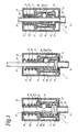
- a locking device 1 comprising locking means 7-9 in the form of sleeves 7,8, a clamping means 9 in the form of locking balls 27 and a housing 11 having gable walls 12,13 provided with openings 14,15 and a hollow formation 16.
- the sleeves 7,8 constitute a female part 17 and a male part 19 having a sleeve extension 18.
- One end 20 of the male part 19 is surrounded by said female part 17 and the other end 21 of which protrudes from the male part 17 having a first spring means 22.
- a second spring means 23 is provided below the female part 17 having a conical formed inner mantle surface 25.
- An opening 24 in the male part 19 is provided with horizontally lying channels 26, which are provided with said locking balls 27.
- step 1 before the wire 10 is inserted into the opening 15, so that the second spring means 23 is pressing up the male part 19 towards the conically formed mantle surface 25 and the second gable wall 13 at the same time as the first spring means 22 is applicated around the male part 19.
- step 2 illustrated when the wire 10 is inserted downwards into the hollow formation 16 and abuts the locking balls 27, which are pressed aside by the wire outwards in a direction towards the conically formed mantle surface 25, so that the male part 19 is pressed downwards a bit and the second spring means 23 is somewhat pressed together.
- the locking balls 27 receive a space to move further aside in the horizontally lying channel 26 to receive a space to pass the wire 10 further through the hollow formation 16 and out through the sleeve extension 18, so that the locking balls 27 are pressed outwards in a direction towards the wire 10 by the pressure from the spring means 22,23. In this way a positioning fixing of the locking device I occurs against the wire 10.
- part view C is illustrated how the fixing into a position is released in a step 3 by pressing the sleeve extension 18 in a direction upwards, so that a space is created for the locking balls 27 to move in a direction from the wire 10 in the horizontally lying channel 26 and the pressing force against the wire is released, so that the locking device can be moved upwards and downwards along the wire 10 for a new fixation into a position at another place to the wire 10.
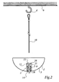
- the detail 2 is illustrated in the form of a cover 3, which is applicated to the housing 11 of the locking device 1.
- the wire 10 is supported by a ceiling 6 in a supporting means 4. Thereafter the wire 10 is passed through the hollow formation 16 of the locking device 1 through the openings 14,15 out through the sleeve extension 18, so that the locking means 7-9 are released somewhat from the wire 10. By pressing in the sleeve extension 18 the locking means 7-9 are further released, so that the cover 3 easier can be displaced further all the way up against the ceiling 6.
- the cover 3 is locked against the wire 10 by the locking means 7-9, when again releasing the pressed in sleeve extension 18, so that the cover 3 is fixed into a position, which is a stop against the ceiling 6 and the cover 3 totally cover the supporting means 4 at the same time as a subsequent spring effect by one of the springs urges the locking device in a direction upwards against the ceiling.
- the load of the cover 3 and an established pressure on the cover 3, in its position against the ceiling is transferred to the free end 21 of the male part 19, so that the locking balls 27, which are already pressing against the Wire 10, in turn are further pressed against the wire 10, when they by the load and pressure are urged further upwards in the conically formed mantle surface 25.
Landscapes
- Engineering & Computer Science (AREA)
- General Engineering & Computer Science (AREA)
- Mechanical Engineering (AREA)
- Clamps And Clips (AREA)
- Emergency Lowering Means (AREA)
- Lock And Its Accessories (AREA)
- Length Measuring Devices With Unspecified Measuring Means (AREA)
- Ropes Or Cables (AREA)
- Flexible Shafts (AREA)
Claims (4)
- Verriegelungsvorrichtung zur justierbaren Befestigung in einer Position an einem Draht oder Seil (10), das durch diese hindurchgeführt wird und die zur Befestigung eines Gegenstands (2) vorgesehen ist, insbesondere einem Montageteil wie beispielsweise einer Abdeckung (3), um ein Haltemittel (4) eines Montageteils an einer Decke (6) zu verdecken, wobei die Vorrichtung Verriegelungsmittel (7-9) aufweist, die miteinander zusammenwirken, indem sie eine Klemmung der Verriegelungsvorrichtung (1) an dem Draht (10) verursachen, wobei die Verriegelungsmittel aus zwei in sich selbst teleskopartig verschiebbaren Muffen (7, 8) bestehen, die in einem Gehäuse oder einer Abdeckung (11) untergebracht sind, an dem das Montageteil (3) befestigt ist und wenigstens ein Klemmmittel (9), das mit diesen zusammenwirkt, wobei das Gehäuse (11) in seinen Giebelwänden (12, 13) Öffnungen (14, 15) aufweist, die im Wesentlichen in einer Linie mit einer hohlen Struktur (16) für den Draht (10) liegen, der sich durch die Muffen (7, 8) hindurch erstreckt, wobei die erste (7) der Muffen (7, 8) ein Führungsteil (17) darstellt, das teilweise die zweite Muffe (8) beinhaltet und die eine Muffenverlängerung (18) beinhaltet, die aus der einen Öffnung (14) des Gehäuses (11) heraussteht, während zur selben Zeit die zweite Muffe (8) ein Steckteil (19) darstellt, dessen eine Ende (20) von dem Führungsteil (17) umgeben ist und dessen zweites freie Ende (21) aus dem Führungsteil (17) heraussteht,
dadurch gekennzeichnet, dass
ein erstes Federmittel (22) an dem freien Ende (21) angeordnet ist, um das Führungsteil (17) in eine Richtung gegen die eine erste Giebelwand (12) zu drücken, die zur Befestigung des Montageteils (3) vorgesehen ist und die dasselbe nach der Montage durch Federspannung in eine Richtung gegen die Decke (6) drückt, während zur selben Zeit ein zweites Federmittel (23) am Führungsteil (17) angeordnet ist, um das Steckteil (19) in eine Richtung gegen die zweite Giebelwand (13) zu drücken, wobei die Klemmmittel (9) in einer an sich bekannten Art und Weise gegen den Draht (10) gedrückt werden können, indem es verschiebbar in einer Öffnung (24) in demjenigen Ende (22) des Steckteils (19) angeordnet ist, dass in dem Führungsteil (17) angeordnet ist, wobei bei der Klemmung der Verriegelungsvorrichtung (1) an dem Draht (10) eine konisch geformte innere Manteloberfläche in dem Führungsteil (17) das Klemmmittel (9) in eine Richtung nach innen gegen den Draht (10) in der hohlen Struktur (16) drückt, während die zweiten Federmittel (23) des Steckteils (19) in eine Richtung gegen die zweite Giebelwand (13) drücken und wobei zur Lockerung der Verriegelungsvorrichtung (1) vom Draht (10) die Federmittel (22, 23) zusammengepresst werden können, indem die Muffenverlängerung (18) in die Öffnung (14) in der benachbarten Giebelwand (12) gedrückt wird, die in Verbindung mit der Außenseite des Montageteils (3) angeordnet ist, sodass die Klemmmittel (9) vom Druck gegen den Draht (10) gelöst werden. - Verriegelungsvorrichtung nach Anspruch 1,
dadurch gekennzeichnet,
dass die Öffnung (24) in dem Steckteil (19) im Wesentlichen aus einem horizontal angeordneten Kanal (26) besteht, der ein Klemmmittel in Form einer Verriegelungskugel (27) beinhaltet, die seitwärts verschieblich in dem Kanal (26) durch das Steckelement (19) angeordnet ist. - Verriegelungsvorrichtung nach einem der Ansprüche 1 oder 2, dadurch gekennzeichnet,
dass die Verriegelungskugeln (27) zur weiteren seitlichen Verschiebung ausreichend Platz erhalten, indem die Muffenverlängerung (18) eingedrückt wird und indem die zweiten Federmittel (23) zusammengepresst werden, sodass der Draht (19) leicht durch die hohle Struktur (16) in der Verriegelungsvorrichtung (1) einführbar und ausführbar durch die Muffenverlängerung (18) ist, wobei die Verriegelungsvorrichtung (1) nach oben und nach unten entlang des Drahts (10) verschoben werden kann. - Verriegelungsvorrichtung nach einem der vorherigen Ansprüche, dadurch gekennzeichnet,
dass die Federmittel (22, 23) aus Schraubenfedern bestehen.
Applications Claiming Priority (2)
| Application Number | Priority Date | Filing Date | Title |
|---|---|---|---|
| SE0300787A SE527336C2 (sv) | 2003-03-24 | 2003-03-24 | Läsanordning för justerbar lägesfixering vid en vajer eller lina |
| PCT/SE2004/000455 WO2004085876A1 (en) | 2003-03-24 | 2004-03-24 | Locking device |
Publications (2)
| Publication Number | Publication Date |
|---|---|
| EP1613877A1 EP1613877A1 (de) | 2006-01-11 |
| EP1613877B1 true EP1613877B1 (de) | 2007-01-24 |
Family
ID=20290748
Family Applications (1)
| Application Number | Title | Priority Date | Filing Date |
|---|---|---|---|
| EP04723124A Expired - Lifetime EP1613877B1 (de) | 2003-03-24 | 2004-03-24 | Verriegelungsvorrichtung |
Country Status (5)
| Country | Link |
|---|---|
| EP (1) | EP1613877B1 (de) |
| AT (1) | ATE352733T1 (de) |
| DE (1) | DE602004004518D1 (de) |
| SE (1) | SE527336C2 (de) |
| WO (1) | WO2004085876A1 (de) |
Families Citing this family (2)
| Publication number | Priority date | Publication date | Assignee | Title |
|---|---|---|---|---|
| DE102005007737B4 (de) * | 2005-02-18 | 2012-03-22 | Seil- & Netztechnik Reutlinger Gmbh | Halter |
| WO2023039801A1 (zh) * | 2021-09-16 | 2023-03-23 | 瑞仪光电(苏州)有限公司 | 固定机构及灯具 |
Family Cites Families (4)
| Publication number | Priority date | Publication date | Assignee | Title |
|---|---|---|---|---|
| AT196185B (de) * | 1955-09-19 | 1958-02-25 | Gustav Haimann | Spanner für Seile, Gurten, Drähte, Stäbe od. dgl. |
| DE4441005A1 (de) * | 1994-11-17 | 1996-05-23 | Gerd Bonus | Seilaufhänger für Pendelleuchten |
| WO1996021123A1 (en) * | 1994-12-29 | 1996-07-11 | Vibeke Kjerrumgaard | Fitting |
| AU6298496A (en) * | 1995-06-23 | 1997-01-22 | Thopatent Data Aps | Fitting |
-
2003
- 2003-03-24 SE SE0300787A patent/SE527336C2/sv not_active IP Right Cessation
-
2004
- 2004-03-24 DE DE602004004518T patent/DE602004004518D1/de not_active Expired - Lifetime
- 2004-03-24 AT AT04723124T patent/ATE352733T1/de not_active IP Right Cessation
- 2004-03-24 EP EP04723124A patent/EP1613877B1/de not_active Expired - Lifetime
- 2004-03-24 WO PCT/SE2004/000455 patent/WO2004085876A1/en not_active Ceased
Also Published As
| Publication number | Publication date |
|---|---|
| EP1613877A1 (de) | 2006-01-11 |
| SE527336C2 (sv) | 2006-02-14 |
| WO2004085876A1 (en) | 2004-10-07 |
| DE602004004518D1 (de) | 2007-03-15 |
| ATE352733T1 (de) | 2007-02-15 |
| SE0300787D0 (sv) | 2003-03-24 |
| SE0300787L (sv) | 2004-09-25 |
Similar Documents
| Publication | Publication Date | Title |
|---|---|---|
| US10478645B2 (en) | Safety removable anchoring device | |
| US10920819B2 (en) | Snap nut concrete anchor assembly | |
| US8651786B2 (en) | Fastening device for mounting on a mounting rail | |
| EP3037711A1 (de) | Teleskopische wasserdichte rohrstruktur | |
| JP2011104380A (ja) | 手術台に付属部品を接続する装置及びその方法 | |
| WO2004032772A3 (fr) | Systeme de fixation a plaque | |
| US7950310B2 (en) | Magnetic structure for a socket | |
| US20140174579A1 (en) | Faucet Assemblies | |
| US10697157B2 (en) | Counter-top rapid installation device for tap | |
| US20250116360A1 (en) | Threaded rod locking devices and methods | |
| EP1613877A1 (de) | Verriegelungsvorrichtung | |
| JP6384526B2 (ja) | 継手用台座 | |
| US7961901B2 (en) | Loudspeaker stand and mount for a loudspeaker stand | |
| US7458141B2 (en) | Methods and devices for installing a garbage disposer | |
| WO2008104157A3 (de) | Steckverbinder | |
| KR200276628Y1 (ko) | 인장재 해체형 앵커 구조물 | |
| ZA200400742B (en) | Suspending equipment | |
| KR20250029093A (ko) | 간접활선 방식으로 설치되는 완철용 브라켓 | |
| JP6188901B1 (ja) | フリーロックジョイント | |
| KR20190000645U (ko) | 케이블타이형 단열재알루미늄거푸집용 간격조절장치 | |
| KR20180118582A (ko) | 확장형 영구 앵커 | |
| KR100953158B1 (ko) | 분기관 연결구 | |
| RU2584425C1 (ru) | Составной анкер для изоляционного материала | |
| JP2003268884A (ja) | アンカーボルト及びアンカーボルトの固定方法 | |
| DE102008045718A1 (de) | Mikrofonhalterung |
Legal Events
| Date | Code | Title | Description |
|---|---|---|---|
| PUAI | Public reference made under article 153(3) epc to a published international application that has entered the european phase |
Free format text: ORIGINAL CODE: 0009012 |
|
| 17P | Request for examination filed |
Effective date: 20051021 |
|
| AK | Designated contracting states |
Kind code of ref document: A1 Designated state(s): AT BE BG CH CY CZ DE DK EE ES FI FR GB GR HU IE IT LI LU MC NL PL PT RO SE SI SK TR |
|
| AX | Request for extension of the european patent |
Extension state: AL LT LV MK |
|
| RBV | Designated contracting states (corrected) |
Designated state(s): AT BE BG CH CY CZ DE DK EE ES FI FR GB GR HU IE IT LI LU MC NL PL PT RO SE SI SK TR |
|
| DAX | Request for extension of the european patent (deleted) | ||
| GRAP | Despatch of communication of intention to grant a patent |
Free format text: ORIGINAL CODE: EPIDOSNIGR1 |
|
| GRAS | Grant fee paid |
Free format text: ORIGINAL CODE: EPIDOSNIGR3 |
|
| GRAA | (expected) grant |
Free format text: ORIGINAL CODE: 0009210 |
|
| AK | Designated contracting states |
Kind code of ref document: B1 Designated state(s): AT BE BG CH CY CZ DE DK EE ES FI FR GB GR HU IE IT LI LU MC NL PL PT RO SE SI SK TR |
|
| PG25 | Lapsed in a contracting state [announced via postgrant information from national office to epo] |
Ref country code: NL Free format text: LAPSE BECAUSE OF FAILURE TO SUBMIT A TRANSLATION OF THE DESCRIPTION OR TO PAY THE FEE WITHIN THE PRESCRIBED TIME-LIMIT Effective date: 20070124 Ref country code: SI Free format text: LAPSE BECAUSE OF FAILURE TO SUBMIT A TRANSLATION OF THE DESCRIPTION OR TO PAY THE FEE WITHIN THE PRESCRIBED TIME-LIMIT Effective date: 20070124 Ref country code: PL Free format text: LAPSE BECAUSE OF FAILURE TO SUBMIT A TRANSLATION OF THE DESCRIPTION OR TO PAY THE FEE WITHIN THE PRESCRIBED TIME-LIMIT Effective date: 20070124 Ref country code: DK Free format text: LAPSE BECAUSE OF FAILURE TO SUBMIT A TRANSLATION OF THE DESCRIPTION OR TO PAY THE FEE WITHIN THE PRESCRIBED TIME-LIMIT Effective date: 20070124 Ref country code: CH Free format text: LAPSE BECAUSE OF FAILURE TO SUBMIT A TRANSLATION OF THE DESCRIPTION OR TO PAY THE FEE WITHIN THE PRESCRIBED TIME-LIMIT Effective date: 20070124 Ref country code: AT Free format text: LAPSE BECAUSE OF FAILURE TO SUBMIT A TRANSLATION OF THE DESCRIPTION OR TO PAY THE FEE WITHIN THE PRESCRIBED TIME-LIMIT Effective date: 20070124 Ref country code: LI Free format text: LAPSE BECAUSE OF FAILURE TO SUBMIT A TRANSLATION OF THE DESCRIPTION OR TO PAY THE FEE WITHIN THE PRESCRIBED TIME-LIMIT Effective date: 20070124 Ref country code: FI Free format text: LAPSE BECAUSE OF FAILURE TO SUBMIT A TRANSLATION OF THE DESCRIPTION OR TO PAY THE FEE WITHIN THE PRESCRIBED TIME-LIMIT Effective date: 20070124 |
|
| REG | Reference to a national code |
Ref country code: GB Ref legal event code: FG4D |
|
| REG | Reference to a national code |
Ref country code: CH Ref legal event code: EP |
|
| REG | Reference to a national code |
Ref country code: IE Ref legal event code: FG4D |
|
| REF | Corresponds to: |
Ref document number: 602004004518 Country of ref document: DE Date of ref document: 20070315 Kind code of ref document: P |
|
| PG25 | Lapsed in a contracting state [announced via postgrant information from national office to epo] |
Ref country code: SE Free format text: LAPSE BECAUSE OF FAILURE TO SUBMIT A TRANSLATION OF THE DESCRIPTION OR TO PAY THE FEE WITHIN THE PRESCRIBED TIME-LIMIT Effective date: 20070424 Ref country code: BG Free format text: LAPSE BECAUSE OF FAILURE TO SUBMIT A TRANSLATION OF THE DESCRIPTION OR TO PAY THE FEE WITHIN THE PRESCRIBED TIME-LIMIT Effective date: 20070424 |
|
| PG25 | Lapsed in a contracting state [announced via postgrant information from national office to epo] |
Ref country code: DE Free format text: LAPSE BECAUSE OF FAILURE TO SUBMIT A TRANSLATION OF THE DESCRIPTION OR TO PAY THE FEE WITHIN THE PRESCRIBED TIME-LIMIT Effective date: 20070425 |
|
| PG25 | Lapsed in a contracting state [announced via postgrant information from national office to epo] |
Ref country code: ES Free format text: LAPSE BECAUSE OF FAILURE TO SUBMIT A TRANSLATION OF THE DESCRIPTION OR TO PAY THE FEE WITHIN THE PRESCRIBED TIME-LIMIT Effective date: 20070505 |
|
| PG25 | Lapsed in a contracting state [announced via postgrant information from national office to epo] |
Ref country code: PT Free format text: LAPSE BECAUSE OF FAILURE TO SUBMIT A TRANSLATION OF THE DESCRIPTION OR TO PAY THE FEE WITHIN THE PRESCRIBED TIME-LIMIT Effective date: 20070625 |
|
| REG | Reference to a national code |
Ref country code: CH Ref legal event code: PL |
|
| NLV1 | Nl: lapsed or annulled due to failure to fulfill the requirements of art. 29p and 29m of the patents act | ||
| EN | Fr: translation not filed | ||
| PG25 | Lapsed in a contracting state [announced via postgrant information from national office to epo] |
Ref country code: SK Free format text: LAPSE BECAUSE OF FAILURE TO SUBMIT A TRANSLATION OF THE DESCRIPTION OR TO PAY THE FEE WITHIN THE PRESCRIBED TIME-LIMIT Effective date: 20070124 |
|
| PLBE | No opposition filed within time limit |
Free format text: ORIGINAL CODE: 0009261 |
|
| STAA | Information on the status of an ep patent application or granted ep patent |
Free format text: STATUS: NO OPPOSITION FILED WITHIN TIME LIMIT |
|
| 26N | No opposition filed |
Effective date: 20071025 |
|
| PG25 | Lapsed in a contracting state [announced via postgrant information from national office to epo] |
Ref country code: RO Free format text: LAPSE BECAUSE OF FAILURE TO SUBMIT A TRANSLATION OF THE DESCRIPTION OR TO PAY THE FEE WITHIN THE PRESCRIBED TIME-LIMIT Effective date: 20070124 Ref country code: BE Free format text: LAPSE BECAUSE OF FAILURE TO SUBMIT A TRANSLATION OF THE DESCRIPTION OR TO PAY THE FEE WITHIN THE PRESCRIBED TIME-LIMIT Effective date: 20070124 Ref country code: CZ Free format text: LAPSE BECAUSE OF FAILURE TO SUBMIT A TRANSLATION OF THE DESCRIPTION OR TO PAY THE FEE WITHIN THE PRESCRIBED TIME-LIMIT Effective date: 20070124 |
|
| PG25 | Lapsed in a contracting state [announced via postgrant information from national office to epo] |
Ref country code: IE Free format text: LAPSE BECAUSE OF NON-PAYMENT OF DUE FEES Effective date: 20070326 Ref country code: MC Free format text: LAPSE BECAUSE OF NON-PAYMENT OF DUE FEES Effective date: 20070331 |
|
| PG25 | Lapsed in a contracting state [announced via postgrant information from national office to epo] |
Ref country code: IT Free format text: LAPSE BECAUSE OF FAILURE TO SUBMIT A TRANSLATION OF THE DESCRIPTION OR TO PAY THE FEE WITHIN THE PRESCRIBED TIME-LIMIT Effective date: 20070124 Ref country code: FR Free format text: LAPSE BECAUSE OF FAILURE TO SUBMIT A TRANSLATION OF THE DESCRIPTION OR TO PAY THE FEE WITHIN THE PRESCRIBED TIME-LIMIT Effective date: 20070914 Ref country code: GR Free format text: LAPSE BECAUSE OF FAILURE TO SUBMIT A TRANSLATION OF THE DESCRIPTION OR TO PAY THE FEE WITHIN THE PRESCRIBED TIME-LIMIT Effective date: 20070425 |
|
| GBPC | Gb: european patent ceased through non-payment of renewal fee |
Effective date: 20080324 |
|
| PG25 | Lapsed in a contracting state [announced via postgrant information from national office to epo] |
Ref country code: FR Free format text: LAPSE BECAUSE OF FAILURE TO SUBMIT A TRANSLATION OF THE DESCRIPTION OR TO PAY THE FEE WITHIN THE PRESCRIBED TIME-LIMIT Effective date: 20070124 |
|
| PG25 | Lapsed in a contracting state [announced via postgrant information from national office to epo] |
Ref country code: EE Free format text: LAPSE BECAUSE OF FAILURE TO SUBMIT A TRANSLATION OF THE DESCRIPTION OR TO PAY THE FEE WITHIN THE PRESCRIBED TIME-LIMIT Effective date: 20070124 |
|
| PG25 | Lapsed in a contracting state [announced via postgrant information from national office to epo] |
Ref country code: GB Free format text: LAPSE BECAUSE OF NON-PAYMENT OF DUE FEES Effective date: 20080324 |
|
| PG25 | Lapsed in a contracting state [announced via postgrant information from national office to epo] |
Ref country code: CY Free format text: LAPSE BECAUSE OF FAILURE TO SUBMIT A TRANSLATION OF THE DESCRIPTION OR TO PAY THE FEE WITHIN THE PRESCRIBED TIME-LIMIT Effective date: 20070124 |
|
| PG25 | Lapsed in a contracting state [announced via postgrant information from national office to epo] |
Ref country code: LU Free format text: LAPSE BECAUSE OF NON-PAYMENT OF DUE FEES Effective date: 20070324 |
|
| PG25 | Lapsed in a contracting state [announced via postgrant information from national office to epo] |
Ref country code: HU Free format text: LAPSE BECAUSE OF FAILURE TO SUBMIT A TRANSLATION OF THE DESCRIPTION OR TO PAY THE FEE WITHIN THE PRESCRIBED TIME-LIMIT Effective date: 20070725 Ref country code: TR Free format text: LAPSE BECAUSE OF FAILURE TO SUBMIT A TRANSLATION OF THE DESCRIPTION OR TO PAY THE FEE WITHIN THE PRESCRIBED TIME-LIMIT Effective date: 20070124 |