EP1612675A2 - Data processing apparatus and method for controlling a communication unit in accordance with a generated error type - Google Patents
Data processing apparatus and method for controlling a communication unit in accordance with a generated error type Download PDFInfo
- Publication number
- EP1612675A2 EP1612675A2 EP05253745A EP05253745A EP1612675A2 EP 1612675 A2 EP1612675 A2 EP 1612675A2 EP 05253745 A EP05253745 A EP 05253745A EP 05253745 A EP05253745 A EP 05253745A EP 1612675 A2 EP1612675 A2 EP 1612675A2
- Authority
- EP
- European Patent Office
- Prior art keywords
- communication
- error
- communication unit
- data
- data process
- Prior art date
- Legal status (The legal status is an assumption and is not a legal conclusion. Google has not performed a legal analysis and makes no representation as to the accuracy of the status listed.)
- Withdrawn
Links
Images




Classifications
-
- G—PHYSICS
- G06—COMPUTING OR CALCULATING; COUNTING
- G06F—ELECTRIC DIGITAL DATA PROCESSING
- G06F3/00—Input arrangements for transferring data to be processed into a form capable of being handled by the computer; Output arrangements for transferring data from processing unit to output unit, e.g. interface arrangements
- G06F3/12—Digital output to print unit, e.g. line printer, chain printer
- G06F3/1201—Dedicated interfaces to print systems
- G06F3/1223—Dedicated interfaces to print systems specifically adapted to use a particular technique
- G06F3/1236—Connection management
-
- H—ELECTRICITY
- H04—ELECTRIC COMMUNICATION TECHNIQUE
- H04N—PICTORIAL COMMUNICATION, e.g. TELEVISION
- H04N23/00—Cameras or camera modules comprising electronic image sensors; Control thereof
-
- G—PHYSICS
- G03—PHOTOGRAPHY; CINEMATOGRAPHY; ANALOGOUS TECHNIQUES USING WAVES OTHER THAN OPTICAL WAVES; ELECTROGRAPHY; HOLOGRAPHY
- G03G—ELECTROGRAPHY; ELECTROPHOTOGRAPHY; MAGNETOGRAPHY
- G03G15/00—Apparatus for electrographic processes using a charge pattern
- G03G15/50—Machine control of apparatus for electrographic processes using a charge pattern, e.g. regulating differents parts of the machine, multimode copiers, microprocessor control
- G03G15/5075—Remote control machines, e.g. by a host
-
- G—PHYSICS
- G03—PHOTOGRAPHY; CINEMATOGRAPHY; ANALOGOUS TECHNIQUES USING WAVES OTHER THAN OPTICAL WAVES; ELECTROGRAPHY; HOLOGRAPHY
- G03G—ELECTROGRAPHY; ELECTROPHOTOGRAPHY; MAGNETOGRAPHY
- G03G15/00—Apparatus for electrographic processes using a charge pattern
- G03G15/55—Self-diagnostics; Malfunction or lifetime display
-
- G—PHYSICS
- G06—COMPUTING OR CALCULATING; COUNTING
- G06F—ELECTRIC DIGITAL DATA PROCESSING
- G06F11/00—Error detection; Error correction; Monitoring
- G06F11/07—Responding to the occurrence of a fault, e.g. fault tolerance
- G06F11/0703—Error or fault processing not based on redundancy, i.e. by taking additional measures to deal with the error or fault not making use of redundancy in operation, in hardware, or in data representation
- G06F11/0706—Error or fault processing not based on redundancy, i.e. by taking additional measures to deal with the error or fault not making use of redundancy in operation, in hardware, or in data representation the processing taking place on a specific hardware platform or in a specific software environment
- G06F11/0733—Error or fault processing not based on redundancy, i.e. by taking additional measures to deal with the error or fault not making use of redundancy in operation, in hardware, or in data representation the processing taking place on a specific hardware platform or in a specific software environment in a data processing system embedded in an image processing device, e.g. printer, facsimile, scanner
-
- G—PHYSICS
- G06—COMPUTING OR CALCULATING; COUNTING
- G06F—ELECTRIC DIGITAL DATA PROCESSING
- G06F11/00—Error detection; Error correction; Monitoring
- G06F11/07—Responding to the occurrence of a fault, e.g. fault tolerance
- G06F11/0703—Error or fault processing not based on redundancy, i.e. by taking additional measures to deal with the error or fault not making use of redundancy in operation, in hardware, or in data representation
- G06F11/0766—Error or fault reporting or storing
- G06F11/0781—Error filtering or prioritizing based on a policy defined by the user or on a policy defined by a hardware/software module, e.g. according to a severity level
-
- G—PHYSICS
- G06—COMPUTING OR CALCULATING; COUNTING
- G06F—ELECTRIC DIGITAL DATA PROCESSING
- G06F11/00—Error detection; Error correction; Monitoring
- G06F11/07—Responding to the occurrence of a fault, e.g. fault tolerance
- G06F11/0703—Error or fault processing not based on redundancy, i.e. by taking additional measures to deal with the error or fault not making use of redundancy in operation, in hardware, or in data representation
- G06F11/0793—Remedial or corrective actions
-
- G—PHYSICS
- G06—COMPUTING OR CALCULATING; COUNTING
- G06F—ELECTRIC DIGITAL DATA PROCESSING
- G06F3/00—Input arrangements for transferring data to be processed into a form capable of being handled by the computer; Output arrangements for transferring data from processing unit to output unit, e.g. interface arrangements
- G06F3/12—Digital output to print unit, e.g. line printer, chain printer
- G06F3/1201—Dedicated interfaces to print systems
- G06F3/1202—Dedicated interfaces to print systems specifically adapted to achieve a particular effect
- G06F3/1203—Improving or facilitating administration, e.g. print management
- G06F3/1209—Improving or facilitating administration, e.g. print management resulting in adapted or bridged legacy communication protocols, e.g. emulation, protocol extension
-
- G—PHYSICS
- G06—COMPUTING OR CALCULATING; COUNTING
- G06F—ELECTRIC DIGITAL DATA PROCESSING
- G06F3/00—Input arrangements for transferring data to be processed into a form capable of being handled by the computer; Output arrangements for transferring data from processing unit to output unit, e.g. interface arrangements
- G06F3/12—Digital output to print unit, e.g. line printer, chain printer
- G06F3/1201—Dedicated interfaces to print systems
- G06F3/1202—Dedicated interfaces to print systems specifically adapted to achieve a particular effect
- G06F3/121—Facilitating exception or error detection and recovery, e.g. fault, media or consumables depleted
-
- G—PHYSICS
- G06—COMPUTING OR CALCULATING; COUNTING
- G06F—ELECTRIC DIGITAL DATA PROCESSING
- G06F3/00—Input arrangements for transferring data to be processed into a form capable of being handled by the computer; Output arrangements for transferring data from processing unit to output unit, e.g. interface arrangements
- G06F3/12—Digital output to print unit, e.g. line printer, chain printer
- G06F3/1201—Dedicated interfaces to print systems
- G06F3/1223—Dedicated interfaces to print systems specifically adapted to use a particular technique
- G06F3/1229—Printer resources management or printer maintenance, e.g. device status, power levels
- G06F3/1234—Errors handling and recovery, e.g. reprinting
-
- G—PHYSICS
- G06—COMPUTING OR CALCULATING; COUNTING
- G06F—ELECTRIC DIGITAL DATA PROCESSING
- G06F3/00—Input arrangements for transferring data to be processed into a form capable of being handled by the computer; Output arrangements for transferring data from processing unit to output unit, e.g. interface arrangements
- G06F3/12—Digital output to print unit, e.g. line printer, chain printer
- G06F3/1201—Dedicated interfaces to print systems
- G06F3/1278—Dedicated interfaces to print systems specifically adapted to adopt a particular infrastructure
- G06F3/1292—Mobile client, e.g. wireless printing
-
- Y—GENERAL TAGGING OF NEW TECHNOLOGICAL DEVELOPMENTS; GENERAL TAGGING OF CROSS-SECTIONAL TECHNOLOGIES SPANNING OVER SEVERAL SECTIONS OF THE IPC; TECHNICAL SUBJECTS COVERED BY FORMER USPC CROSS-REFERENCE ART COLLECTIONS [XRACs] AND DIGESTS
- Y02—TECHNOLOGIES OR APPLICATIONS FOR MITIGATION OR ADAPTATION AGAINST CLIMATE CHANGE
- Y02D—CLIMATE CHANGE MITIGATION TECHNOLOGIES IN INFORMATION AND COMMUNICATION TECHNOLOGIES [ICT], I.E. INFORMATION AND COMMUNICATION TECHNOLOGIES AIMING AT THE REDUCTION OF THEIR OWN ENERGY USE
- Y02D10/00—Energy efficient computing, e.g. low power processors, power management or thermal management
Definitions
- the present invention relates to a data process apparatus for controlling communication by a communication unit in accordance with a generated error type, and a method of controlling the same.
- a direct print method of directly transferring a taken image from an imaging device to a printing device for printing for example, Japanese Patent Application Laid-opne No. H11-008831.
- a standard rule is defined in accordance with CAMERA & IMAGING PRODUCTS ASSOCIATION (CIPA).
- CIPA CAMERA & IMAGING PRODUCTS ASSOCIATION
- transfer and printing can be executed directly between the imaging device and the printing device through the mutual connection, independently of manufacturers and models of the imaging device and the printing device.
- the printing device repeats the process for receiving the data of only the quantity that can be received at one time, and carrying out the printing process while maintaining a communication link for data transfer, and then sequentially receiving the data corresponding to a buffer amount that becomes free after the printing process from the imaging device.
- an error such as jam, paper-out or ink-out
- a suitable process must be performed to cope with the error even in the communication unit maintaining the communication link.
- the control method of the communication unit waits for the recovery of the error while maintaining the connection between the printing device and the imaging device.
- the foregoing problems are generated in the communications between the various devices, not only between the imaging device and the printing device, but also between the imaging device and a personal computer, between the imaging device and a storage device such as a hard disc device between the personal computer and the printing device, and the like.
- An object of the present invention is to flexibly control a communication status between apparatuses in accordance with a generated error type.
- Another object of the present invention is to improve a communication efficiency when an error is generated and reduce a power consumption.
- Fig. 1 shows an imaging device 101 and a printing device 102 according to an embodiment of the present invention.
- the imaging device 101 uses a wireless communication method based on Bluetooth communication to transfer a print request to the printing device (printer) 102.
- the printing device 102 obtains, in response to the print request received from the imaging device 101, the image data specified in the print request from the imaging device 101 and carries out the printing.
- the Bluetooth of the wireless communication method is used as the wireless communication.
- wireless LAN such as IEEE802. 11a/b/g/h/e, Ultra Wide Band (UWB) and other wireless communications are noted here.
- UWB Ultra Wide Band
- the construction of the imaging device 101 of this embodiment will be described by using the function block diagram shown in Fig. 2.
- the imaging device 101 includes at least a wireless communication unit 201, a power unit 202, an image process unit 203 and a storage unit 204.
- the imaging device 101 has a function for carrying out a wireless communication with a peripheral terminal.
- the power unit 202 supplies predetermined voltages and currents to the respective units of the imaging device 101.
- the image process unit 203 has a function for carrying out an imaging process that is the main function of the imaging device 101.
- the storage unit 204 has a function for storing a program required to control the imaging device 101 and storing data such as an image taken by an image process unit 203, and is constituted by a storage medium such as a memory or a card.
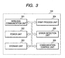
- the printing device 102 includes at least a wireless communication unit 301, a power unit 302, a storage unit 303, a print process unit 304, an error detection unit 305 and a communication control unit 306.
- the printing device 102 has a function for carrying out a wireless communication with a peripheral terminal.
- the power unit 302 supplies predetermined voltages and currents to the respective units of the printing device 102.
- the storage unit 303 has a function for storing a program required to control the printing device 102, data transferred by the imaging device 101 and the like, and is constituted by a storage medium such as a memory, a card or a hard disc drive.
- the print process unit 304 has a function for carrying out a print process, which is the main function of the printing device 102.
- the error detection unit 305 has: a function for detecting an error generated in the printer, actuating the communication control unit 306, and notifying the type of the generated error to the communication control unit 306; and a function for notifying the error through the wireless communication unit 301 to the imaging device 101.
- the communication control unit 306 has a function for controlling the communication status with the imaging device 101 and carries out a process for transiting the communication status to a low power consumption mode in accordance with the type of the generated printer error or disconnecting the connection. Moreover, the communication control unit has a function for returning the communication status to the status prior to the error generation and restarting the data transfer, when the communication status is the low power consumption mode at the time of the error recovery.
- the communication control unit 306 discriminates the error by referring to an error discrimination table stored in the storage unit 303, on the basis of error information notified by the error detection unit 305.
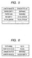
- Fig. 5 shows an example of the error discrimination table. As shown in Fig. 5, each error is classified into: [Warning] implying the error where a recovery is possible while a communication is maintained; and [Fatal Error] implying the error where the recovery is difficult if the communication is maintained.
- the communication control unit 306 transmits a status notice including the information with regard to the generated error, such as an error reason and an error status, through the wireless communication unit 301 to the imaging device 101.
- Fig. 6 shows an example of data in the status notice.
- the status notice includes at least the information of [Printer status ([Pause] indicating suspension or [Printing] indicating print execution)], [Error status] and [Error Reason].
- the communication control unit 306 examines whether or not the error status obtained by referring to the error discrimination table at the step S401 is [Fatal Error].
- the communication control unit 306 instructs the wireless communication unit 301 to finish the communication with the imaging device 101. Then, the wireless communication unit 301 finishes the communication with the imaging device 101.
- the communication control unit 306 instructs the wireless communication unit 301 to change the communication status with the imaging device 101 to the low power consumption mode.
- a park mode is indicated as the low power consumption mode of Bluetooth.
- the wireless communication unit 301 transmits a park mode request to the imaging device 101.
- the communication between the imaging device 101 and the printing device 102 is interrupted to transit to the park mode.
- the unit that transits to the park mode may be the wireless communication unit 301 of the printing device 102 or may be the wireless communication unit 201 of the imaging device 101.
- the wireless communication unit 201 of the imaging device 101 may be preferably transited to the park mode.
- the printing device 102 transits the wireless communication unit 201 of the imaging device 101 to the park mode.
- the transition to the park mode may not be executed.
- both of a wireless communication unit 801 of the printing device 102 and a wireless communication unit 701 of the imaging device 101 may be transited to the low power consumption mode.
- the communication control unit 306 monitors the status of the printer and waits for the recovery of the printer error.
- the communication control unit 306 instructs the wireless communication unit 301 to release the park mode.
- the wireless communication unit 301 transmits a park mode release request to the imaging device 101. On reception of a message agreeing to the park mode release from the wireless communication unit 201 of the imaging device 101, the park mode is released.
- the imaging device 101 and the printing device 102 restart the interrupted data transfer.
- the wireless communication between the imaging device and the printing device is preferably controlled on the, basis of the error status and type of the printing device.
- the wireless communication is set in the low power consumption mode.
- the wireless communication is disconnected. Consequently, the wasteful power consumption can be avoided.
- the printing can be quickly restarted without any imposition of the complex operation on the user. Thus, the communication efficiency at the time of the error generation can be improved.
- the first embodiment relates to the method in which when the error is generated in the printing device 102, the printing device 102 takes the lead and controls the status of the wireless communication between the imaging device 101 and the printing device 102, on the basis of the error status.
- the direct print method is assumed to be carried out between the various combinations of the printing device and the imaging device, independently of manufacturers and devices. For this reason, it may be considered that the control described in the first embodiment cannot be executed by the printing device.
- the imaging device 101 when the error is generated in the printing device 102, on the basis of the error status information notified by the printing device 102, the imaging device 101 takes the lead and controls the status of the wireless communication between the imaging device 101 and the printing device 102. Consequently, even when the status of the wireless communication cannot be controlled under the lead of the printing device as in the first embodiment, the control is carried out under the lead of the imaging device 101. Thus, the effect similar to that of the first embodiment can be obtained.
- the imaging device 101 includes at least a wireless communication unit 701, a power unit 702, an image process unit 703, a storage unit 704, a printer error detection unit 705 and a communication control unit 706.
- the imaging device 101 has a function for carrying out a wireless communication with a peripheral terminal.
- the power unit 702 supplies predetermined voltages and currents to the respective units of the imaging device 101.
- the image process unit 703 has a function for carrying out an imaging process that is the main function of the imaging device 101.
- the storage unit 704 has a function for storing a program required to control the imaging device 101 and storing data such as an image taken by an image process unit 203, and is constituted by a storage medium such as a memory, a card or a hard disc drive. Also, in this embodiment, the storage unit 704 stores the error discrimination table as shown in Fig. 5.
- the printer error detection unit 705 has a function for detecting the printer error generation and error type from the error notice transferred by the printing device 102, starting the communication control unit 706, and notifying the type of the generated error to the communication control unit 706.
- the communication control unit 706 has a function for controlling the communication status with the printing device 102 and carries out a process for transiting the communication status to the low power consumption mode in accordance with the type of the generated printer error or disconnecting the connection. Moreover, the communication control unit has a function for returning the communication status to the status prior to the error generation and restarting the data transfer when the communication status is the low power consumption mode at the time of the error recovery.
- the printing device 102 at least includes a wireless communication unit 801, a power unit 802, a storage unit 803, a print process unit 804 and an error detection unit 805.
- the printing device 102 has a function for carrying out a wireless communication with a peripheral terminal.
- the power unit 802 supplies predetermined voltages and currents to the respective units of the printing device 102.
- the storage unit 803 has a function for storing a program required to control the printing device 102, data transferred by the imaging device 101 and the like, and is constituted by a storage medium such as a memory, a card or a hard disc drive.
- the print process unit 804 has a function for carrying out a print process, which is the main function of the printing device 102.
- the error detection unit 805 has a function for detecting the error generated in the printer and notifying the error through a wireless communication unit 801 to the imaging device 101.
- Fig. 9 is a flowchart showing the process procedure of the communication control unit 706 until the transition to the low power consumption mode after the error notice reception.
- the printing device 102 when the error is detected by the error detection unit 805 during the print process, notifies the imaging device 101 of the error and the type of the generated error.
- the type of the error notified by the printing device 102 is the information corresponding to the error reason in Fig. 5.
- the error detection unit 705 refers to the error status in the message notified by the imaging device 101 and notifies the communication control unit 706 of the status of the printer error obtained therein.
- the communication control unit 706 examines whether or not the error status obtained at the step S901 is [Fatal Error], by referring to the error discrimination table (Fig. 5) stored in the storage unit 704.
- the communication control unit 706 instructs the wireless communication unit 701 to finish the communication with the printing device 102. Then, the wireless communication unit 701 finishes the communication with the printing device 102.
- the communication control unit 706 instructs the wireless communication unit 701 to change the communication status with the printing device 102 to a low power consumption mode.
- a hold mode is indicated as the low power consumption mode of Bluetooth.
- the wireless communication unit 701 transmits a hold mode request to the printing device 102.
- the communication between the imaging device 101 and the printing device 102 is interrupted to transit to the hold mode.
- the unit that transits to the hold mode may be the wireless communication unit 801 of the printing device 102 or may be the wireless communication unit 701 of the imaging device 101.
- the wireless communication unit 701 of the imaging device 101 may be preferably transited to the hold mode.
- the printing device 102 transits the wireless communication unit 701 of the imaging device 101 to the hold mode.
- the transition to the hold mode may not be executed.
- both of a wireless communication unit 801 of the printing device 102 and a wireless communication unit 701 of the imaging device 101 may be transited to the low power consumption mode.
- the wireless communication unit 701 transmits a hold mode request to the printing device 102, and the communication between the imaging device 101 and the printing device 102 is transited to the hold mode.
- the hold mode request is received in advance by the printing device 102.
- the hold mode agreement message is transited to the hold mode.
- a hold mode continuation time (defined as a time T in this embodiment) is described in the hold mode request. Then, the wireless communication units 701 and 801 of the imaging device 101 and the printing device 102 release the hold mode at the elapse of the time T after the transition to the hold mode and return back to the status where the normal communication can be executed.
- the communication control unit 706 transmits a status notice request to obtain the status of the printing device 102, through the wireless communication unit 701 to the printing device 102.
- the printing device 102 transmits: the status data as to whether the error is recovered or continuous; and the type of the continuous error, as a status notice response message to the imaging device 101.
- the status notice response message including the status information shown in Fig. 6 is transmitted to the imaging device 101.
- the device is not still recovered from the error.
- [Pause] is stored in the printer status information.
- the communication control unit 706 refers to the printer status information in the received status notice response message, and since the printer status is [Pause], discriminates that the device is not still recovered from the printer error. Then, the communication control unit again transmits the hold mode request to the printing device 102 and transits to the hold mode.
- the communication control unit 706 refers to the printer status information by using the procedure similar to the steps 1002 and 1003, and since the printer status is [Printing], discriminates that the printing device 102 is recovered from the error, and restarts the interrupted data transfer.
- the printer in addition to the effect of the first embodiment, even when the printer does not have any function for carrying out the control of the wireless communication as in the first embodiment, wasteful power consumption can be avoided. Also, without any imposition of the complex operation on the user, the printing can be quickly restarted, which can also improve the communication efficiency at the time of the error generation.
- the communication between the imaging device and the printing device has been explained.
- the present invention can be also applied to communications between the various devices, such as communication between the imaging device and the personal computer, communication between the imaging device and the storage device such as the hard disc device, and communication between the personal computer and the printing device.
- the communication status between the devices can be softly controlled in accordance with the error type of the data process device. Also, the communication efficiency when the error is generated can be improved.
- the low power consumption when the error is generated can be attained.
- the present invention can be implemented by a computer program operating in a data processing apparatus.
- An aspect of the present invention thus provides a storage medium storing processor implementable instructions for controlling a processor to carry out the method as hereinabove described.
Landscapes
- Engineering & Computer Science (AREA)
- Theoretical Computer Science (AREA)
- Physics & Mathematics (AREA)
- General Physics & Mathematics (AREA)
- General Engineering & Computer Science (AREA)
- Human Computer Interaction (AREA)
- Quality & Reliability (AREA)
- Computer Vision & Pattern Recognition (AREA)
- Computer Networks & Wireless Communication (AREA)
- Microelectronics & Electronic Packaging (AREA)
- Multimedia (AREA)
- Signal Processing (AREA)
- Accessory Devices And Overall Control Thereof (AREA)
- Studio Devices (AREA)
- Communication Control (AREA)
- Maintenance And Management Of Digital Transmission (AREA)
Abstract
Description
- The present invention relates to a data process apparatus for controlling communication by a communication unit in accordance with a generated error type, and a method of controlling the same. Related Background Art
- There is a direct print method of directly transferring a taken image from an imaging device to a printing device for printing (for example, Japanese Patent Application Laid-opne No. H11-008831). In this method, a standard rule is defined in accordance with CAMERA & IMAGING PRODUCTS ASSOCIATION (CIPA). In the case of the imaging device and printing device according to this standard rule, transfer and printing can be executed directly between the imaging device and the printing device through the mutual connection, independently of manufacturers and models of the imaging device and the printing device.
- In the process of the direct printing, the printing device repeats the process for receiving the data of only the quantity that can be received at one time, and carrying out the printing process while maintaining a communication link for data transfer, and then sequentially receiving the data corresponding to a buffer amount that becomes free after the printing process from the imaging device. Here, if an error, such as jam, paper-out or ink-out, is generated during the printing process in a printing mechanism of the printing device, a suitable process must be performed to cope with the error even in the communication unit maintaining the communication link. Conventionally, when such an error is generated, the control method of the communication unit waits for the recovery of the error while maintaining the connection between the printing device and the imaging device.
- However, in the conventional method, it could not be said that flexible communication control based on the error status of the printing device was carried out when the error was generated in the printing device. For example, there is a problem in that unnecessary power is wastefully consumed because the communication is maintained even during the error recovering operation where the communication is not executed. Also, in order to eliminate the waste of power consumption, if the communication is disconnected when the error is generated in the printing device, the error recovery cannot be notified to the imaging device. Thus, there are problems in that a user itself must discriminate whether recovery of the error is attained, a connection operation must be again executed at a time of printing restart, etc. This leads to other problems in that it takes a time to restart the printing and the user needs to execute a troublesome operation in order to restart the printing.
- The foregoing problems are generated in the communications between the various devices, not only between the imaging device and the printing device, but also between the imaging device and a personal computer, between the imaging device and a storage device such as a hard disc device between the personal computer and the printing device, and the like.
- An object of the present invention is to flexibly control a communication status between apparatuses in accordance with a generated error type.
- Another object of the present invention is to improve a communication efficiency when an error is generated and reduce a power consumption.
- Other objects of the present invention will be evident from the following specification and drawings.
-
- Fig. 1 shows an example according to an embodiment of the present invention;
- Fig. 2 is a construction view of a function block of an imaging device according to a first embodiment;
- Fig. 3 is a construction view of a function block of a printer according to the first embodiment;
- Fig. 4 is a flowchart showing a process procedure of a control unit in the printer;
- Fig. 5 shows an example in an error discrimination table;
- Fig. 6 shows an example in a data in a status notice;
- Fig. 7 is a construction view of a function block of an imaging device according to a second embodiment;
- Fig. 8 is a construction view of a function block of a printer according to the second embodiment;
- Fig. 9 is a flowchart showing a process procedure of a control unit in the imaging device; and
- Fig. 10 is an operation explanation view of a communication control mainly executed by the imaging device in the second embodiment.
- The best mode for carrying out the present invention will be described below with reference to the drawings.
- Fig. 1 shows an
imaging device 101 and aprinting device 102 according to an embodiment of the present invention. - In this embodiment, the
imaging device 101 uses a wireless communication method based on Bluetooth communication to transfer a print request to the printing device (printer) 102. Theprinting device 102 obtains, in response to the print request received from theimaging device 101, the image data specified in the print request from theimaging device 101 and carries out the printing. - Also, in this embodiment, the Bluetooth of the wireless communication method is used as the wireless communication. However, the applicable facts even in wireless LAN, such as IEEE802. 11a/b/g/h/e, Ultra Wide Band (UWB) and other wireless communications are noted here.
- The construction of the
imaging device 101 of this embodiment will be described by using the function block diagram shown in Fig. 2. - The
imaging device 101 includes at least awireless communication unit 201, apower unit 202, animage process unit 203 and astorage unit 204. - In the
wireless communication unit 201, theimaging device 101 has a function for carrying out a wireless communication with a peripheral terminal. - The
power unit 202 supplies predetermined voltages and currents to the respective units of theimaging device 101. - The
image process unit 203 has a function for carrying out an imaging process that is the main function of theimaging device 101. - The
storage unit 204 has a function for storing a program required to control theimaging device 101 and storing data such as an image taken by animage process unit 203, and is constituted by a storage medium such as a memory or a card. - The construction of the
printing device 102 of this embodiment will be described below by using a function block diagram shown in Fig. 3. - The
printing device 102 includes at least awireless communication unit 301, apower unit 302, astorage unit 303, aprint process unit 304, anerror detection unit 305 and acommunication control unit 306. - In the
wireless communication unit 301, theprinting device 102 has a function for carrying out a wireless communication with a peripheral terminal. - The
power unit 302 supplies predetermined voltages and currents to the respective units of theprinting device 102. - The
storage unit 303 has a function for storing a program required to control theprinting device 102, data transferred by theimaging device 101 and the like, and is constituted by a storage medium such as a memory, a card or a hard disc drive. - The
print process unit 304 has a function for carrying out a print process, which is the main function of theprinting device 102. - The
error detection unit 305 has: a function for detecting an error generated in the printer, actuating thecommunication control unit 306, and notifying the type of the generated error to thecommunication control unit 306; and a function for notifying the error through thewireless communication unit 301 to theimaging device 101. - The
communication control unit 306 has a function for controlling the communication status with theimaging device 101 and carries out a process for transiting the communication status to a low power consumption mode in accordance with the type of the generated printer error or disconnecting the connection. Moreover, the communication control unit has a function for returning the communication status to the status prior to the error generation and restarting the data transfer, when the communication status is the low power consumption mode at the time of the error recovery. - The process procedure when the
printing device 102 detects the error will be described below by using a flowchart shown in Fig. 4. - At a step S401, the
communication control unit 306 discriminates the error by referring to an error discrimination table stored in thestorage unit 303, on the basis of error information notified by theerror detection unit 305. Fig. 5 shows an example of the error discrimination table. As shown in Fig. 5, each error is classified into: [Warning] implying the error where a recovery is possible while a communication is maintained; and [Fatal Error] implying the error where the recovery is difficult if the communication is maintained. - At a step S402, the
communication control unit 306 transmits a status notice including the information with regard to the generated error, such as an error reason and an error status, through thewireless communication unit 301 to theimaging device 101. Fig. 6 shows an example of data in the status notice. As shown in Fig. 6, the status notice includes at least the information of [Printer status ([Pause] indicating suspension or [Printing] indicating print execution)], [Error status] and [Error Reason]. - At a step S403, the
communication control unit 306 examines whether or not the error status obtained by referring to the error discrimination table at the step S401 is [Fatal Error]. - At a step S403, when the error status is [Fatal Error], at a step S404, the
communication control unit 306 instructs thewireless communication unit 301 to finish the communication with theimaging device 101. Then, thewireless communication unit 301 finishes the communication with theimaging device 101. - At the step S403, when the error status is [Warning], at a step S405, the
communication control unit 306 instructs thewireless communication unit 301 to change the communication status with theimaging device 101 to the low power consumption mode. In this embodiment, suppose that a park mode is indicated as the low power consumption mode of Bluetooth. Thewireless communication unit 301 transmits a park mode request to theimaging device 101. Then, on reception of a message agreeing to the park mode request from awireless communication unit 201 of theimaging device 101, the communication between theimaging device 101 and theprinting device 102 is interrupted to transit to the park mode. Here, the unit that transits to the park mode may be thewireless communication unit 301 of theprinting device 102 or may be thewireless communication unit 201 of theimaging device 101. However, since theimaging device 101 is operated by a battery in many cases, thewireless communication unit 201 of theimaging device 101 may be preferably transited to the park mode. In this case, when the communication between theimaging device 101 and theprinting device 102 is started, whether or not the battery operation is being executed is notified to each other. When theimaging device 101 is being operated by the battery, theprinting device 102 transits thewireless communication unit 201 of theimaging device 101 to the park mode. Also, when both of them are not operated by the battery, the transition to the park mode may not be executed. Also, both of awireless communication unit 801 of theprinting device 102 and awireless communication unit 701 of theimaging device 101 may be transited to the low power consumption mode. - At a step S406, the
communication control unit 306 monitors the status of the printer and waits for the recovery of the printer error. - At a step S407, when the printer error is corrected and the
communication control unit 306 recognizes the recovery from the printer error, thecommunication control unit 306 instructs thewireless communication unit 301 to release the park mode. Thewireless communication unit 301 transmits a park mode release request to theimaging device 101. On reception of a message agreeing to the park mode release from thewireless communication unit 201 of theimaging device 101, the park mode is released. - After the release of the park mode, the
imaging device 101 and theprinting device 102 restart the interrupted data transfer. - With the above-mentioned procedure, the control of the communication status is carried out when the printer error is generated during the printing.
- According to the first embodiment as mentioned above, the wireless communication between the imaging device and the printing device is preferably controlled on the, basis of the error status and type of the printing device. Concretely, when the error that may be easily recovered is generated such as the paper-out or the jam, the wireless communication is set in the low power consumption mode. When the error whose recovery requires a long time, such as the ink-out or the error requiring the re-start is generated, the wireless communication is disconnected. Consequently, the wasteful power consumption can be avoided. Also, in the case of the low power consumption mode, the printing can be quickly restarted without any imposition of the complex operation on the user. Thus, the communication efficiency at the time of the error generation can be improved.
- The first embodiment relates to the method in which when the error is generated in the
printing device 102, theprinting device 102 takes the lead and controls the status of the wireless communication between theimaging device 101 and theprinting device 102, on the basis of the error status. - By the way, the direct print method is assumed to be carried out between the various combinations of the printing device and the imaging device, independently of manufacturers and devices. For this reason, it may be considered that the control described in the first embodiment cannot be executed by the printing device.
- So, in the second embodiment, when the error is generated in the
printing device 102, on the basis of the error status information notified by theprinting device 102, theimaging device 101 takes the lead and controls the status of the wireless communication between theimaging device 101 and theprinting device 102. Consequently, even when the status of the wireless communication cannot be controlled under the lead of the printing device as in the first embodiment, the control is carried out under the lead of theimaging device 101. Thus, the effect similar to that of the first embodiment can be obtained. - The construction of the
imaging device 101 in this embodiment will be described below by using the function block diagram shown in Fig. 7. - The
imaging device 101 includes at least awireless communication unit 701, apower unit 702, animage process unit 703, astorage unit 704, a printererror detection unit 705 and acommunication control unit 706. - In the
wireless communication unit 701, theimaging device 101 has a function for carrying out a wireless communication with a peripheral terminal. - The
power unit 702 supplies predetermined voltages and currents to the respective units of theimaging device 101. - The
image process unit 703 has a function for carrying out an imaging process that is the main function of theimaging device 101. - The
storage unit 704 has a function for storing a program required to control theimaging device 101 and storing data such as an image taken by animage process unit 203, and is constituted by a storage medium such as a memory, a card or a hard disc drive. Also, in this embodiment, thestorage unit 704 stores the error discrimination table as shown in Fig. 5. - The printer
error detection unit 705 has a function for detecting the printer error generation and error type from the error notice transferred by theprinting device 102, starting thecommunication control unit 706, and notifying the type of the generated error to thecommunication control unit 706. - The
communication control unit 706 has a function for controlling the communication status with theprinting device 102 and carries out a process for transiting the communication status to the low power consumption mode in accordance with the type of the generated printer error or disconnecting the connection. Moreover, the communication control unit has a function for returning the communication status to the status prior to the error generation and restarting the data transfer when the communication status is the low power consumption mode at the time of the error recovery. - The construction of the
printing device 102 of this embodiment will be described below by using a function block diagram shown in Fig. 3. - The
printing device 102 at least includes awireless communication unit 801, apower unit 802, astorage unit 803, aprint process unit 804 and anerror detection unit 805. - In the
wireless communication unit 801, theprinting device 102 has a function for carrying out a wireless communication with a peripheral terminal. - The
power unit 802 supplies predetermined voltages and currents to the respective units of theprinting device 102. - The
storage unit 803 has a function for storing a program required to control theprinting device 102, data transferred by theimaging device 101 and the like, and is constituted by a storage medium such as a memory, a card or a hard disc drive. - The
print process unit 804 has a function for carrying out a print process, which is the main function of theprinting device 102. Theerror detection unit 805 has a function for detecting the error generated in the printer and notifying the error through awireless communication unit 801 to theimaging device 101. - The process procedure when the error is generated in the
printing device 102 during the print process and then theerror detection unit 805 of theprinting device 102 notifies theimaging device 101 of the error status through thewireless communication unit 801 will be described below by using Figs. 9 and 10. - Fig. 9 is a flowchart showing the process procedure of the
communication control unit 706 until the transition to the low power consumption mode after the error notice reception. - The
printing device 102, when the error is detected by theerror detection unit 805 during the print process, notifies theimaging device 101 of the error and the type of the generated error. Here, the type of the error notified by theprinting device 102 is the information corresponding to the error reason in Fig. 5. - At a step S901, the
error detection unit 705 refers to the error status in the message notified by theimaging device 101 and notifies thecommunication control unit 706 of the status of the printer error obtained therein. - At a step S902, the
communication control unit 706 examines whether or not the error status obtained at the step S901 is [Fatal Error], by referring to the error discrimination table (Fig. 5) stored in thestorage unit 704. - At the step S902, when the error status is [Fatal Error], at a step S903, the
communication control unit 706 instructs thewireless communication unit 701 to finish the communication with theprinting device 102. Then, thewireless communication unit 701 finishes the communication with theprinting device 102. - At the step S902, when the error status is [Warning], at a step S904, the
communication control unit 706 instructs thewireless communication unit 701 to change the communication status with theprinting device 102 to a low power consumption mode. In this embodiment, suppose that a hold mode is indicated as the low power consumption mode of Bluetooth. Thewireless communication unit 701 transmits a hold mode request to theprinting device 102. Then, on reception of a message agreeing to the hold mode request from awireless communication unit 801, the communication between theimaging device 101 and theprinting device 102 is interrupted to transit to the hold mode. Here, the unit that transits to the hold mode may be thewireless communication unit 801 of theprinting device 102 or may be thewireless communication unit 701 of theimaging device 101. However, since theimaging device 101 is operated by a battery in many cases, thewireless communication unit 701 of theimaging device 101 may be preferably transited to the hold mode. In this case, when the communication between theimaging device 101 and theprinting device 102 is started, whether or not the battery operation is being executed is notified to each other. When theimaging device 101 is being operated by the battery, theprinting device 102 transits thewireless communication unit 701 of theimaging device 101 to the hold mode. Also, when both of them are not operated by the battery, the transition to the hold mode may not be executed. Also, both of awireless communication unit 801 of theprinting device 102 and awireless communication unit 701 of theimaging device 101 may be transited to the low power consumption mode. - The process procedure of the
communication control unit 706 in the case of releasing the hold mode during the hold mode and after the error recovery will be described below by using the operation explanation view shown in Fig. 10. - At a step S1001, in accordance with the instruction of the
communication control unit 706, thewireless communication unit 701 transmits a hold mode request to theprinting device 102, and the communication between theimaging device 101 and theprinting device 102 is transited to the hold mode. Here, in the process illustrated in the flowchart of Fig. 9 as mentioned above, the hold mode request is received in advance by theprinting device 102. Thus, without any reception of a hold mode agreement message from theprinting device 102, it is transited to the hold mode. - A hold mode continuation time (defined as a time T in this embodiment) is described in the hold mode request. Then, the
wireless communication units imaging device 101 and theprinting device 102 release the hold mode at the elapse of the time T after the transition to the hold mode and return back to the status where the normal communication can be executed. - At a step S1002, at the elapse of the time T after the transition to the hold mode, the
communication control unit 706 transmits a status notice request to obtain the status of theprinting device 102, through thewireless communication unit 701 to theprinting device 102. - At a step S1003, as the response of the status notice request of the step S1002, the
printing device 102 transmits: the status data as to whether the error is recovered or continuous; and the type of the continuous error, as a status notice response message to theimaging device 101. Note that, when theprinter 101 has the table shown in Fig. 6, the status notice response message including the status information shown in Fig. 6 is transmitted to theimaging device 101. In this case, in the status notice response message at this step of Fig. 10, the device is not still recovered from the error. Thus, [Pause] is stored in the printer status information. - At a step S1004, the
communication control unit 706 refers to the printer status information in the received status notice response message, and since the printer status is [Pause], discriminates that the device is not still recovered from the printer error. Then, the communication control unit again transmits the hold mode request to theprinting device 102 and transits to the hold mode. - At steps S1005 and S1006, when the error recovery is carried out in the previous hold mode, the
communication control unit 706 refers to the printer status information by using the procedure similar to thesteps 1002 and 1003, and since the printer status is [Printing], discriminates that theprinting device 102 is recovered from the error, and restarts the interrupted data transfer. - With the above-mentioned procedure, the control of the communication status is carried out when the printer error is generated during the printing.
- As mentioned above, according to the second embodiment, in addition to the effect of the first embodiment, even when the printer does not have any function for carrying out the control of the wireless communication as in the first embodiment, wasteful power consumption can be avoided. Also, without any imposition of the complex operation on the user, the printing can be quickly restarted, which can also improve the communication efficiency at the time of the error generation.
- In the explanations of the respective embodiments, the communication between the imaging device and the printing device has been explained. However, the present invention can be also applied to communications between the various devices, such as communication between the imaging device and the personal computer, communication between the imaging device and the storage device such as the hard disc device, and communication between the personal computer and the printing device.
- According to the present invention, the communication status between the devices can be softly controlled in accordance with the error type of the data process device. Also, the communication efficiency when the error is generated can be improved.
- Also, the low power consumption when the error is generated can be attained.
- This application claims priority from Japanese Patent Application No. 2004-191627 filed June 29, 2004, which is hereby incorporated by reference herein.
- The present invention can be implemented by a computer program operating in a data processing apparatus. An aspect of the present invention thus provides a storage medium storing processor implementable instructions for controlling a processor to carry out the method as hereinabove described.
Claims (14)
- A data process apparatus that communicates data by a communication unit, comprising:a discrimination device for discriminating an error type generated in the data process apparatus or a communication partner apparatus; and
characterized in that
a selection device for executing selectively a process for setting the communication by the communication unit in a low power consumption mode, and a process for disconnecting the communication with the partner apparatus by the communication unit, in accordance with the discrimination of the discrimination device. - A data process apparatus according to claim 1, wherein the discrimination device discriminates whether the generated error is a first type error that can be recovered after a process of reception data is interrupted, or a second type error that cannot be recovered unless the process of the reception data is finished.
- A data process apparatus according to claim 2, wherein the selection device, when the discrimination device discriminates that the generated error is the first type error, sets the communication by the communication unit in a low power consumption mode, and when it is discriminated to be the second type error, disconnects the communication by the communication unit with the partner apparatus.
- A data process apparatus according to claim 1, wherein the selection device executes selectively one of a process for setting the communication unit in the low power consumption mode, and a process for disconnecting the communication by the communication unit with the partner apparatus, in accordance with the discrimination of the discrimination device.
- A data process apparatus according to claim 1, wherein the selection device executes selectively a process for setting a communication unit of the partner apparatus in the low power consumption mode, and a process for disconnecting the communication by the communication unit with the partner apparatus, in accordance with the discrimination of the discrimination device.
- A data process apparatus according to claim 1, wherein the selection device executes the process, in accordance with whether the data process apparatus or the partner apparatus is being operated by a battery.
- A data process apparatus according to claim 1, wherein the data process apparatus is a printing apparatus, and the discrimination device discriminates an error type generated during a print process.
- A data process apparatus according to claim 7, wherein when the discrimination device discriminates a paper-out or jam, the selection device executes a process for setting the communication by the communication unit in the low power consumption mode.
- A data process apparatus according to claim 7, wherein when the discrimination device discriminates recording material out, the selection device executes the process for disconnecting the communication by the communication unit with the partner apparatus.
- A data process apparatus according to claim 1, wherein the discrimination device discriminates an error type generated in the communication partner apparatus, in accordance with information notified from the communication partner apparatus.
- A data process apparatus according to claim 1, wherein the communication partner apparatus is a printing apparatus, and the discrimination device discriminates an error type generated during a print process in the printing apparatus.
- A method of controlling a data process apparatus that communicates data by a communication unit, comprising:a discriminating step of discriminating an error type generated in the data process apparatus or a communication partner apparatus; and
characterized in that
a selecting step of executing selectively a process for setting the communication by the communication unit in a low power consumption mode, and a process for disconnecting the communication with the partner apparatus by the communication unit, in accordance with the discrimination in the discriminating step. - A program, which can be read by a computer, for controlling a data process apparatus that communicates data by a communication unit, comprising:a discriminating step of discriminating an error type generated in the data process apparatus or a communication partner apparatus; and
characterized in that
a selecting step of executing selectively a process for setting the communication by the communication unit in a low power consumption mode, and a process for disconnecting the communication with the partner apparatus by the communication unit, in accordance with the discrimination in the discriminating step. - A storage medium storing processor implementable instructions for controlling an apparatus when executed to carry out all of the steps of a method as claimed in claim 12.
Applications Claiming Priority (1)
| Application Number | Priority Date | Filing Date | Title |
|---|---|---|---|
| JP2004191627A JP4994582B2 (en) | 2004-06-29 | 2004-06-29 | DATA PROCESSING DEVICE FOR DATA COMMUNICATION, DATA PROCESSING DEVICE CONTROL METHOD, AND COMPUTER PROGRAM |
Publications (2)
| Publication Number | Publication Date |
|---|---|
| EP1612675A2 true EP1612675A2 (en) | 2006-01-04 |
| EP1612675A3 EP1612675A3 (en) | 2009-07-22 |
Family
ID=35094554
Family Applications (1)
| Application Number | Title | Priority Date | Filing Date |
|---|---|---|---|
| EP05253745A Withdrawn EP1612675A3 (en) | 2004-06-29 | 2005-06-16 | Data processing apparatus and method for controlling a communication unit in accordance with a generated error type |
Country Status (5)
| Country | Link |
|---|---|
| US (1) | US7318679B2 (en) |
| EP (1) | EP1612675A3 (en) |
| JP (1) | JP4994582B2 (en) |
| KR (1) | KR100753063B1 (en) |
| CN (1) | CN100401739C (en) |
Families Citing this family (8)
| Publication number | Priority date | Publication date | Assignee | Title |
|---|---|---|---|---|
| JP4362782B2 (en) * | 2005-06-30 | 2009-11-11 | ブラザー工業株式会社 | Image printing apparatus and error information output program for image printing apparatus |
| JP5247262B2 (en) * | 2008-06-30 | 2013-07-24 | キヤノン株式会社 | Wireless communication system, wireless communication apparatus, wireless communication apparatus control method, and program |
| JP2010231365A (en) * | 2009-03-26 | 2010-10-14 | Canon Inc | COMMUNICATION DEVICE, ITS CONTROL METHOD, AND PROGRAM |
| JP6025303B2 (en) * | 2011-02-14 | 2016-11-16 | キヤノン株式会社 | Printing control apparatus, method and program |
| JP5437416B2 (en) * | 2012-02-29 | 2014-03-12 | 京セラドキュメントソリューションズ株式会社 | Print data processing apparatus and program |
| JP2018005854A (en) * | 2016-07-08 | 2018-01-11 | 株式会社リコー | Electronic device and power control method |
| JP6769255B2 (en) * | 2016-11-18 | 2020-10-14 | セイコーエプソン株式会社 | Printing device and control method of printing device |
| JP2021124998A (en) * | 2020-02-06 | 2021-08-30 | 京セラドキュメントソリューションズ株式会社 | Job management system, terminal device, communication control program, image forming device and job management program |
Family Cites Families (22)
| Publication number | Priority date | Publication date | Assignee | Title |
|---|---|---|---|---|
| JPH02131980A (en) * | 1988-11-14 | 1990-05-21 | Asahi Optical Co Ltd | Laser printer |
| JPH03172924A (en) * | 1989-12-01 | 1991-07-26 | Fuji Photo Film Co Ltd | Printer control system |
| JPH06282127A (en) * | 1993-03-26 | 1994-10-07 | Brother Ind Ltd | Printing device |
| US5897252A (en) * | 1993-04-28 | 1999-04-27 | Canon Kabushiki Kaisha | Peripheral device control method and printing apparatus |
| DE69523724T2 (en) * | 1994-12-14 | 2002-08-01 | Canon K.K., Tokio/Tokyo | Image forming apparatus |
| US5819013A (en) * | 1995-10-18 | 1998-10-06 | Canon Kabushiki Kaisha | Communication apparatus having a printer controlling recording in accordance with a bilateral record correction valve |
| JPH10228365A (en) | 1997-02-14 | 1998-08-25 | Canon Inc | Printing apparatus, printing system, and printing method |
| JP3956431B2 (en) | 1997-06-17 | 2007-08-08 | 富士フイルム株式会社 | Electronic camera with composite photo function |
| JP3939825B2 (en) * | 1997-09-09 | 2007-07-04 | オリンパス株式会社 | Electronic camera |
| JP3524361B2 (en) | 1997-12-27 | 2004-05-10 | キヤノン株式会社 | Printer device capable of wireless communication, wireless communication device, and control method thereof |
| JP3715772B2 (en) * | 1998-02-04 | 2005-11-16 | キヤノン株式会社 | Host computer, data processing method, and computer-readable storage medium |
| JP3360665B2 (en) * | 1999-03-12 | 2002-12-24 | セイコーエプソン株式会社 | Electronic printing apparatus having power saving mode and control method |
| JP2000339118A (en) | 1999-05-26 | 2000-12-08 | Nec Corp | Print controller method and printer and recording medium recording print control program |
| JP3559757B2 (en) * | 2000-08-22 | 2004-09-02 | キヤノン株式会社 | Communication method and communication device |
| JP3816748B2 (en) * | 2000-12-27 | 2006-08-30 | 富士通株式会社 | Information processing device |
| JP3833128B2 (en) * | 2001-03-19 | 2006-10-11 | キヤノン株式会社 | Printing apparatus, power control method, program |
| JP2002356038A (en) * | 2001-05-30 | 2002-12-10 | Canon Inc | Image forming device |
| JP3534099B2 (en) * | 2001-10-12 | 2004-06-07 | ミノルタ株式会社 | Imaging printing system, digital camera and printer |
| JP3817494B2 (en) * | 2002-04-22 | 2006-09-06 | キヤノン株式会社 | Image processing apparatus and control method thereof |
| JP3627723B2 (en) | 2002-04-26 | 2005-03-09 | 村田機械株式会社 | Communication terminal device |
| JPWO2004009362A1 (en) * | 2002-07-19 | 2005-11-17 | セイコーエプソン株式会社 | Printing system |
| US7278705B2 (en) * | 2003-05-13 | 2007-10-09 | Canon Kabushiki Kaisha | Power management control method and printing apparatus |
-
2004
- 2004-06-29 JP JP2004191627A patent/JP4994582B2/en not_active Expired - Fee Related
-
2005
- 2005-06-16 EP EP05253745A patent/EP1612675A3/en not_active Withdrawn
- 2005-06-28 US US11/169,994 patent/US7318679B2/en not_active Expired - Lifetime
- 2005-06-28 CN CNB200510080906XA patent/CN100401739C/en not_active Expired - Fee Related
- 2005-06-29 KR KR1020050056872A patent/KR100753063B1/en not_active Expired - Fee Related
Also Published As
| Publication number | Publication date |
|---|---|
| JP2006014192A (en) | 2006-01-12 |
| JP4994582B2 (en) | 2012-08-08 |
| EP1612675A3 (en) | 2009-07-22 |
| US7318679B2 (en) | 2008-01-15 |
| KR100753063B1 (en) | 2007-08-31 |
| KR20060048681A (en) | 2006-05-18 |
| US20050286949A1 (en) | 2005-12-29 |
| CN1716997A (en) | 2006-01-04 |
| CN100401739C (en) | 2008-07-09 |
Similar Documents
| Publication | Publication Date | Title |
|---|---|---|
| US8213026B2 (en) | Image processing apparatus and method providing improved power saving | |
| US7283262B2 (en) | Image forming apparatus and power control method | |
| US9274738B2 (en) | Information processing apparatus, control method and storage medium storing program for short distance wireless communication | |
| JP5967979B2 (en) | Information processing apparatus, information processing system control method, information processing apparatus control method, and program | |
| US8953198B2 (en) | Communication system, communication apparatus, and communication control method | |
| US20130229683A1 (en) | Apparatus and control method thereof | |
| US9172548B2 (en) | Communication apparatus, control method and storage medium | |
| WO2004012075A1 (en) | Print system | |
| EP2669745A2 (en) | Image forming apparatus, image forming method, and print system | |
| EP1612675A2 (en) | Data processing apparatus and method for controlling a communication unit in accordance with a generated error type | |
| US20150156364A1 (en) | Print control apparatus, method for controlling print control apparatus, and storage medium | |
| JP2002280925A (en) | Wireless communication device, storage medium, and program | |
| US8472058B2 (en) | Image processing device, image processing method, and program | |
| JP2001253152A (en) | Digital multifunction peripheral with uninterruptible power supply and control method thereof | |
| JP4641355B2 (en) | Proxy processing management system, proxy processing management device, control method, and storage medium | |
| JP2014108545A (en) | Printer, control method of printer and program | |
| JP6289094B2 (en) | Network interface device and control method thereof | |
| JP2012159941A (en) | Computer program and print data transmitting device | |
| JP2002029118A (en) | Printing equipment | |
| JP2002127508A (en) | Printing equipment | |
| US8325360B2 (en) | Image forming apparatus and image forming method | |
| JP2026074594A (en) | Control method for image processing device, image processing device | |
| JP2002055789A (en) | Image forming device | |
| JP2003266889A (en) | Printer and printer control method | |
| JP2006159759A (en) | Wireless network printer |
Legal Events
| Date | Code | Title | Description |
|---|---|---|---|
| PUAI | Public reference made under article 153(3) epc to a published international application that has entered the european phase |
Free format text: ORIGINAL CODE: 0009012 |
|
| AK | Designated contracting states |
Kind code of ref document: A2 Designated state(s): AT BE BG CH CY CZ DE DK EE ES FI FR GB GR HU IE IS IT LI LT LU MC NL PL PT RO SE SI SK TR |
|
| AX | Request for extension of the european patent |
Extension state: AL BA HR LV MK YU |
|
| PUAL | Search report despatched |
Free format text: ORIGINAL CODE: 0009013 |
|
| AK | Designated contracting states |
Kind code of ref document: A3 Designated state(s): AT BE BG CH CY CZ DE DK EE ES FI FR GB GR HU IE IS IT LI LT LU MC NL PL PT RO SE SI SK TR |
|
| AX | Request for extension of the european patent |
Extension state: AL BA HR LV MK YU |
|
| 17P | Request for examination filed |
Effective date: 20100122 |
|
| AKX | Designation fees paid |
Designated state(s): DE FI FR GB SE |
|
| 17Q | First examination report despatched |
Effective date: 20100621 |
|
| STAA | Information on the status of an ep patent application or granted ep patent |
Free format text: STATUS: THE APPLICATION HAS BEEN WITHDRAWN |
|
| 18W | Application withdrawn |
Effective date: 20150610 |