EP1612626A1 - Spiral à courbe extérieure modifiée - Google Patents
Spiral à courbe extérieure modifiée Download PDFInfo
- Publication number
- EP1612626A1 EP1612626A1 EP04015578A EP04015578A EP1612626A1 EP 1612626 A1 EP1612626 A1 EP 1612626A1 EP 04015578 A EP04015578 A EP 04015578A EP 04015578 A EP04015578 A EP 04015578A EP 1612626 A1 EP1612626 A1 EP 1612626A1
- Authority
- EP
- European Patent Office
- Prior art keywords
- curve
- outside
- spiral
- hairspring
- deformation
- Prior art date
- Legal status (The legal status is an assumption and is not a legal conclusion. Google has not performed a legal analysis and makes no representation as to the accuracy of the status listed.)
- Granted
Links
- 238000004026 adhesive bonding Methods 0.000 description 6
- 239000000463 material Substances 0.000 description 3
- 238000005259 measurement Methods 0.000 description 3
- 238000012360 testing method Methods 0.000 description 3
- 241000287828 Gallus gallus Species 0.000 description 2
- 230000032683 aging Effects 0.000 description 2
- 238000010276 construction Methods 0.000 description 2
- 230000008602 contraction Effects 0.000 description 2
- 239000003292 glue Substances 0.000 description 2
- 238000012986 modification Methods 0.000 description 2
- 230000004048 modification Effects 0.000 description 2
- 230000001105 regulatory effect Effects 0.000 description 2
- 238000003466 welding Methods 0.000 description 2
- 206010054197 Gait deviation Diseases 0.000 description 1
- 238000005452 bending Methods 0.000 description 1
- 230000000052 comparative effect Effects 0.000 description 1
- 230000002596 correlated effect Effects 0.000 description 1
- 230000000875 corresponding effect Effects 0.000 description 1
- 230000001955 cumulated effect Effects 0.000 description 1
- 238000000151 deposition Methods 0.000 description 1
- 230000008021 deposition Effects 0.000 description 1
- 238000013461 design Methods 0.000 description 1
- 238000006073 displacement reaction Methods 0.000 description 1
- 238000004519 manufacturing process Methods 0.000 description 1
- 238000000034 method Methods 0.000 description 1
- 230000000717 retained effect Effects 0.000 description 1
Images
Classifications
-
- G—PHYSICS
- G04—HOROLOGY
- G04B—MECHANICALLY-DRIVEN CLOCKS OR WATCHES; MECHANICAL PARTS OF CLOCKS OR WATCHES IN GENERAL; TIME PIECES USING THE POSITION OF THE SUN, MOON OR STARS
- G04B18/00—Mechanisms for setting frequency
- G04B18/02—Regulator or adjustment devices; Indexing devices, e.g. raquettes
- G04B18/026—Locking the hair spring in the indexing device, e.g. goupille of the raquette
-
- G—PHYSICS
- G04—HOROLOGY
- G04B—MECHANICALLY-DRIVEN CLOCKS OR WATCHES; MECHANICAL PARTS OF CLOCKS OR WATCHES IN GENERAL; TIME PIECES USING THE POSITION OF THE SUN, MOON OR STARS
- G04B17/00—Mechanisms for stabilising frequency
- G04B17/04—Oscillators acting by spring tension
- G04B17/06—Oscillators with hairsprings, e.g. balance
- G04B17/066—Manufacture of the spiral spring
Definitions
- the present invention relates to a hairspring, intended in particular to be integrated in the balance-sprung adjusting device of a timepiece, whose curve on the outside is modified to precisely define the active length of said hairspring, in thus helping to reduce the daytime gap.
- the invention relates more particularly to the means for fixing the curve outside the cock, directly or via a pin usually supported by a movable pin holder for positioning the hairspring.
- the usual fastening by pinning or gluing has the disadvantage of not guaranteeing over time the positioning of the point of contraction / expansion of the hairspring, either because of a slight displacement, or by the aging and / or crumbling of glue.
- the present invention therefore aims to overcome the disadvantages of the aforementioned prior art by providing a spiral whose outer curve can be fixed by the known techniques, without requiring modification of the piton and whose contraction / expansion point, also called embedding point, undergoes no change over time.
- the subject of the invention is a spiral comprising a plurality of turns for a balance-sprung adjusting device in which the curve inside is integral with a pivot axis pivoted in the cock allowing directly or indirectly the attachment of the curve outside said hairspring, said curve having its end stiffened by deformation to define precisely the embedding point, whatever the means used for fixing.
- the deformation is effected by means of a 90 ° twist of the end of the curve outside in a plane perpendicular to the height of the spiral, preferably in the extension of the median axis. turns.
- fixing is carried out for example by gluing in the slot of a peg secured to the cock, or a peg holder. It will be observed that the torsion of the end of the curve to the outside does not modify the width of the spiral blade, so that no modification of the peak is necessary. Thus, the embedding point no longer depends on the way in which the glue is applied, nor on the aging, but on the point stiffened by the twisting of the end of the spiral.
- the deformation is performed by bending the end of the curve outwardly at 180 ° against the inner or outer face of said end, and optionally making a gluing or welding to maintain the folding more securely. wherein the folded distal portion defines the embedding point.
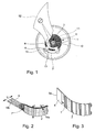
- Figure 1 there is shown a sprung balance adjusting device in top view partially cut away, limited to parts useful for understanding the invention.
- the regulating device comprises a rocker 10 allowing the attachment of the curve inside 4 of the spiral by means of a shell 5 driven on the rocker shaft 11.
- This fixing of the curve inside 4 can obviously be carried out by any other means known to those skilled in the art.
- the curve on the outside is made integral with the cock 12.
- this attachment is made by embedding in a stud 15 fixed in a stud holder 13, said embedding being generally performed by gluing.
- Usually the end of the curve outside, of generally rectangular section (h e) is in the extension of turns 3, with the exception of the Breguet spiral which is hardly used any more.
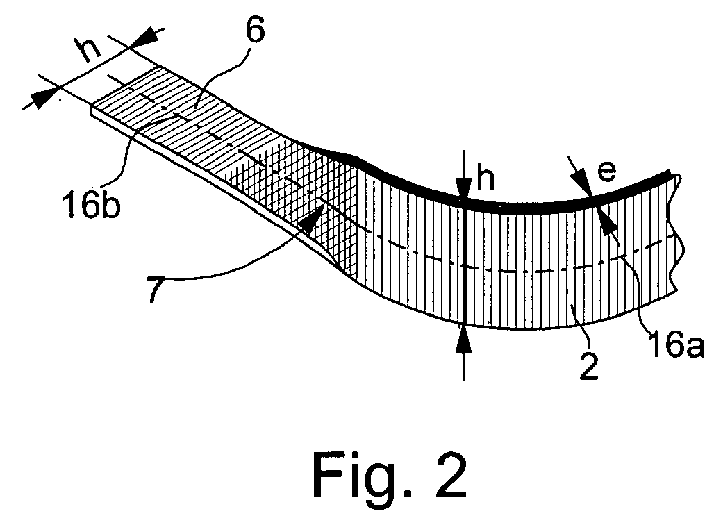
- the present invention aims instead to deform the end 6 of the curve to the outside so that the nesting point 7 of the hairspring is no longer defined by the pin 15 but by the hairspring itself where it was stiffened, as shown in Figure 2.
- the creation of the embedding point 7 is obtained by performing a 90 ° twist of the end 6 of the curve outside 2 , so as to bring said end in a plane perpendicular to the height "h" of the turns, the central line 16a of the turns being preferably in the extension of the center line 16b of the bent portion 6.
- the embedding point 7, defining the active length of the hairspring is formed by folding at 180 ° a portion 8 (corresponding to the portion 6 of the preceding example) at 180.degree. ° against the outer face of the outside curve 2, or in an equivalent manner against the inner face.
- the parts in contact can be held in place by gluing, welding or any other equivalent means.
- a first series of measurements was made with a hairspring whose end 6 curved at 90 ° is abutted in the through hole of the peak.
- the average period measured is then 418065 ⁇ s.
- the average period measured is 418061 ⁇ s, a difference of 4 ⁇ s quite negligible.
- the period difference should be 604 ⁇ s.
- the average period measured is 418010 ⁇ s, a difference of 55 ⁇ s with respect to the first series of measurements, which is approximately 11 times lower than the value that could be expected for an unwound spiral. This value can be correlated with an increase in the stiffness of the spiral blade by a factor of 11 since the other blade construction parameters (h, e and length) remained unchanged.
Landscapes
- Physics & Mathematics (AREA)
- General Physics & Mathematics (AREA)
- Engineering & Computer Science (AREA)
- Manufacturing & Machinery (AREA)
- Springs (AREA)
- Impact Printers (AREA)
- Diaphragms For Electromechanical Transducers (AREA)
- Ropes Or Cables (AREA)
- Developing Agents For Electrophotography (AREA)
- Adornments (AREA)
- Motor Power Transmission Devices (AREA)
Abstract
Description
- La présente invention a pour objet un spiral, destiné en particulier à être intégré dans le dispositif réglant balancier-spiral d'une pièce d'horlogerie, dont la courbe à l'extérieur est modifiée pour définir avec précision la longueur active dudit spiral, en contribuant ainsi à réduire l'écart de marche diurne.
- Il est bien connu que l'isochronisme d'un dispositif réglant balancier-spiral peut être perturbé par les variations des conditions extérieures, telles que la température et le champ magnétique. Pour compenser ou réduire l'influence de ces variations, de nombreuses solutions ont été proposées et/ou retenues au niveau du choix des matériaux, ou de la conformation du balancier et du spiral.
- En ce qui concerne le spiral, la conformation de la courbe à l'intérieur pour la fixation sur l'axe de balancier, la conformation de la courbe à l'extérieur pour la fixation au coq, et les moyens d'effectuer lesdites fixations jouent un rôle déterminant au niveau de l'isochronisme. L'invention concerne plus particulièrement les moyens de fixation de la courbe à l'extérieur au coq, directement ou par l'intermédiaire d'un piton généralement supporté par un porte-piton mobile permettant de positionner le spiral.
- La fixation de la courbe du spiral à l'extérieur est le plus souvent effectuée par goupillage ou collage, bien que d'autres solutions aient été proposées. Il a par exemple été proposé d'ajouter à l'extrémité de la courbe à l'extérieur du spiral une masselotte destinée à être encastrée dans un bord du coq, comme décrit par exemple dans le brevet US 1 037 741, dans lequel la masselotte a une forme triangulaire. Une telle construction rend plus compliquée la fabrication du spiral pour former une masselotte à une extrémité et nécessite un agencement particulier du coq, différent de l'agencement usuel avec piton.
- La fixation usuelle par goupillage ou collage a l'inconvénient de ne pas garantir au cours du temps le positionnement du point de contraction/expansion du spiral, soit en raison d'un léger déplacement, soit par le vieillissement et/ou l'effritement de la colle.
- La présente invention vise donc à pallier les inconvénients de l'art antérieur précité en procurant un spiral dont la courbe à l'extérieur peut être fixée par les techniques connues, sans nécessiter de modification du piton et dont le point de contraction/expansion, également nommé point d'encastrement, ne subit aucune modification au cours du temps.
- A cet effet l'invention a pour objet un spiral comportant une pluralité de spires pour un dispositif réglant balancier-spiral dans lequel la courbe à l'intérieur est solidaire d'un axe de balancier pivoté dans le coq permettant directement ou indirectement la fixation de la courbe à l'extérieur dudit spiral, ladite courbe ayant son extrémité rigidifiée par déformation pour définir avec précision le point d'encastrement, quels que soient les moyens utilisés pour la fixation.
- Selon un premier mode de réalisation la déformation est effectuée au moyen d'une torsion à 90° de l'extrémité de la courbe à l'extérieur dans un plan perpendiculaire à la hauteur du spiral, de préférence dans le prolongement de l'axe médian des spires. Lorsque la fixation est effectuée par exemple par collage dans la fente d'un piton solidaire du coq, ou d'un porte-piton. On observera que la torsion de l'extrémité de la courbe à l'extérieur ne modifie pas la largeur de la lame du spiral, de sorte qu'aucune modification du piton n'est nécessaire. Ainsi le point d'encastrement ne dépend plus de la façon dont est mise la colle, ni du vieillissement, mais du point rigidifié par la torsion de l'extrémité du spiral.
- Selon un deuxième mode de réalisation la déformation est effectuée en repliant à 180° l'extrémité de la courbe à l'extérieur contre la face intérieure ou extérieure de ladite extrémité, et en effectuant éventuellement un collage ou un soudage pour maintenir plus sûrement le pliage dans lequel la partie distale repliée définit le point d'encastrement.
- D'autres caractéristiques et avantages de la présente invention apparaîtront dans la description qui suit, donnée à titre illustratif et non limitatif, en référence aux dessins annexés dans lesquels :
- la figure 1 représente en vue de dessus partiellement arrachée un balancier-spiral pourvu d'un spiral selon l'invention,
- la figure 2 est une représentation agrandie en perspective de l'extrémité de la courbe à l'extérieur du spiral de la figure 1 selon un premier mode de réalisation, et
- la figure 3 correspond à la figure 2 selon un deuxième mode de réalisation.
- A la figure 1 on a représenté un dispositif réglant balancier-spiral en vue de dessus partiellement arrachée, en se limitant aux parties utiles à la compréhension de l'invention.
- Le dispositif réglant comprend un balancier 10 permettant la fixation de la courbe à l'intérieur 4 du spiral au moyen d'une virole 5 chassée sur l'axe de balancier 11. Cette fixation de la courbe à l'intérieur 4 peut évidemment être effectuée par tout autre moyen connu de l'homme de l'art. La courbe à l'extérieur est rendue solidaire du coq 12. Dans l'exemple représenté, cette fixation est effectuée par encastrement dans un piton 15 fixé dans un porte-piton 13, ledit encastrement étant généralement effectué par collage. De façon usuelle l'extrémité de la courbe à l'extérieur, de section généralement rectangulaire (h. e) est dans le prolongement des spires 3, si on fait exception du spiral Breguet qui n'est plus guère utilisé.
- La présente invention vise au contraire à déformer l'extrémité 6 de la courbe à l'extérieur de sorte que point d'encastrement 7 du spiral n'est plus défini par le piton 15 mais par le spiral lui-même à l'endroit où il a été rigidifié, comme représenté sur la figure 2. Comme on le voit dans cet exemple, la création du point d'encastrement 7 est obtenue en effectuant une torsion à 90° de l'extrémité 6 de la courbe à l'extérieur 2, de façon à amener ladite extrémité dans un plan perpendiculaire à la hauteur "h" des spires, la ligne médiane 16a des spires étant de préférence dans le prolongement de la ligne médiane 16b de la partie recourbée 6.
- Dans un deuxième mode de réalisation représenté à la figure 3, le point d'encastrement 7, définissant la longueur active du spiral, est formé en repliant à 180° une portion 8 (correspondant à la portion 6 de l'exemple précédent) à 180° contre la face extérieure de la courbe à l'extérieur 2, ou de façon équivalente contre la face intérieure. Les parties en contact peuvent être maintenues en place par collage, soudure ou tout autre moyen équivalent.
- On rapporte maintenant ci-après deux exemples d'essais comparatifs montrant les avantages que procure un spiral selon l'invention ayant une courbe à l'extérieur modifiée selon le premier mode de réalisation.
- On a réalisé une première série de mesures avec un spiral dont l'extrémité 6 recourbée à 90° est mise en butée dans le trou traversant du piton. La période moyenne mesurée est alors de 418065 µs. En effectuant avec le même spiral 15 poses et déposes successives, dans les mêmes conditions expérimentales, la période moyenne mesurée est de 418061 µs, soit un écart 4 µs tout à fait négligeable.
- Dans une deuxième série de mesures l'extrémité 6 n'a pas été mise en butée mais a été décalée d'un angle de 3° mesuré par rapport à l'axe du balancier. D'après les théories horlogères, l'écart de période devrait être de 604 µs. Toutefois, avec un spiral selon l'invention, la période moyenne mesurée est de 418010 µs, soit un écart de 55 µs par rapport à la première série de mesures, ce qui est environ 11 fois inférieur à la valeur qu'on pouvait attendre pour un spiral non plié. Cette valeur peut être corrélée à une augmentation de la rigidité de la lame du spiral d'un facteur 11 étant donné que les autres paramètres de construction de la lame (h, e et longueur) sont restés inchangés.
- Dans cet exemple on a pris quatre spiraux différents (A, B, C, D) dont la courbe à l'extérieur a été modifiée selon le premier mode de réalisation, et on a comparé les écarts de marche diurne (seconde/jour) pour trois positions de fixation de la courbe à l'extérieur. Dans une première position la partie recourbée 6 est en butée dans le trou du piton, dans une deuxième position ladite partie 6 est légèrement retirée et dans la troisième position on l'a décalée d'un angle α = 7° par rapport à l'axe de balancier. Il est précisé que le but de cet essai n'était pas de réaliser un dispositif réglant balancier-spiral ayant un écart de marche nul, mais de comparer des écarts de marche. Les résultats sont rapportés dans le tableau ci-après.
Spiral A Spiral B Spiral C Spiral D Position 1 - 334,4 - 283,1 - 358,0 - 310,4 Position 2 - 335,4 - 285,2 - 345,4 - 320,2 Position 3 -341,5 -290,4 -350,4 -315,9 Ecart maxi (secondes) 7,1 7,3 12,6 9.8 - Cet essai montre à l'évidence que cette nouvelle conception de la courbe à l'extérieur fait passer en arrière plan la précision de l'encastrement dans le piton.
- Il est bien évident que l'homme de métier peut, sans sortir du cadre de la présente invention modifier et rigidifier l'extrémité d'encastrement de la courbe à l'extérieur, sans effectuer d'apport de matière et quel que soit le matériau utilisé pour réaliser ledit spiral. De même les avantages de la présente invention peuvent être cumulés avec d'autres perfectionnements qui seraient réalisées au niveau de la courbe à l'intérieur.
Claims (5)
- Spiral (1) comportant une pluralité de spires (3) pour un dispositif réglant balancier-spiral dans lequel la courbe à l'intérieur (4) est solidaire d'un axe de balancier (11) pivoté dans le coq (12) permettant directement ou indirectement la fixation de la courbe à l'extérieur (2) dudit spiral (1), caractérisé en ce que l'extrémité (6, 8) de la courbe à l'extérieur (2) est rigidifiée par déformation pour définir avec précision le point d'encastrement (7) dudit spiral.
- Spiral selon la revendication 1, caractérisé en ce que la déformation est effectuée en effectuant une torsion à 90° de l'extrémité (6) de courbe à l'extérieur (2) dans un plan perpendiculaire à la hauteur du spiral (1).
- Spiral selon la revendication 2, caractérisé en ce que l'axe médian de l'extrémité recourbée (6) est dans le prolongement de l'axe médian des spires (3).
- Spiral selon la revendication 1, caractérisé en ce que la déformation est effectuée en repliant à 180° une portion de l'extrémité (8) de la courbe à l'extérieur (2) contre la face intérieure ou extérieure de ladite extrémité (2).
- Spiral selon la revendication 4, caractérisé en ce que la partie recourbée à 180° est collée ou soudée contre la face interne ou externe de l'extrémité (8) de la courbe à l'extérieur (2).
Priority Applications (10)
| Application Number | Priority Date | Filing Date | Title |
|---|---|---|---|
| AT04015578T ATE466315T1 (de) | 2004-07-02 | 2004-07-02 | Spiralfeder mit modifizierter aussenkurve |
| DE602004026849T DE602004026849D1 (de) | 2004-07-02 | 2004-07-02 | Spiralfeder mit modifizierter Aussenkurve |
| EP04015578A EP1612626B1 (fr) | 2004-07-02 | 2004-07-02 | Spiral à courbe extérieure modifiée |
| KR1020050056395A KR20060048631A (ko) | 2004-07-02 | 2005-06-28 | 변경된 외부커브를 가진 밸런스-스프링 |
| TW094121652A TWI369591B (en) | 2004-07-02 | 2005-06-28 | Balance-spring with altered outer curve |
| US11/169,912 US7293913B2 (en) | 2004-07-02 | 2005-06-30 | Balance-spring with altered outer curve |
| RU2005120602/28A RU2366991C2 (ru) | 2004-07-02 | 2005-07-01 | Балансирная пружина с изменяемой внешней спиралью |
| CN2005100806254A CN1716133B (zh) | 2004-07-02 | 2005-07-04 | 具有变型外曲线的游丝 |
| JP2005194989A JP4642569B2 (ja) | 2004-07-02 | 2005-07-04 | 変更された外側曲線部分を有するてんぷばね |
| HK06106954.5A HK1086896B (en) | 2004-07-02 | 2006-06-19 | Balance-spring with altered outer curve |
Applications Claiming Priority (1)
| Application Number | Priority Date | Filing Date | Title |
|---|---|---|---|
| EP04015578A EP1612626B1 (fr) | 2004-07-02 | 2004-07-02 | Spiral à courbe extérieure modifiée |
Publications (2)
| Publication Number | Publication Date |
|---|---|
| EP1612626A1 true EP1612626A1 (fr) | 2006-01-04 |
| EP1612626B1 EP1612626B1 (fr) | 2010-04-28 |
Family
ID=34925587
Family Applications (1)
| Application Number | Title | Priority Date | Filing Date |
|---|---|---|---|
| EP04015578A Expired - Lifetime EP1612626B1 (fr) | 2004-07-02 | 2004-07-02 | Spiral à courbe extérieure modifiée |
Country Status (9)
| Country | Link |
|---|---|
| US (1) | US7293913B2 (fr) |
| EP (1) | EP1612626B1 (fr) |
| JP (1) | JP4642569B2 (fr) |
| KR (1) | KR20060048631A (fr) |
| CN (1) | CN1716133B (fr) |
| AT (1) | ATE466315T1 (fr) |
| DE (1) | DE602004026849D1 (fr) |
| RU (1) | RU2366991C2 (fr) |
| TW (1) | TWI369591B (fr) |
Cited By (2)
| Publication number | Priority date | Publication date | Assignee | Title |
|---|---|---|---|---|
| DE202013007838U1 (de) | 2013-09-04 | 2013-11-13 | Nivarox-Far S.A. | Spiralunruh-Stelleinrichtung für eine mechanische Uhr |
| DE202013010213U1 (de) | 2013-11-13 | 2014-02-05 | Nivarox-Far S.A. | Spiralunruh-Stelleinrichtung für eine mechanische Uhr |
Families Citing this family (9)
| Publication number | Priority date | Publication date | Assignee | Title |
|---|---|---|---|---|
| USD591191S1 (en) * | 2007-06-26 | 2009-04-28 | Maurice Lacroix Sa | Balance wheel with flat hairspring |
| EP2184653A1 (fr) * | 2008-11-06 | 2010-05-12 | Montres Breguet S.A. | Spiral à élévation de courbe en matériau micro-usinable |
| EP2196867A1 (fr) * | 2008-12-15 | 2010-06-16 | Montres Breguet S.A. | Spiral à élévation de courbe en matériau à base de silicium |
| EP2570871B1 (fr) * | 2011-09-14 | 2014-03-19 | Montres Breguet SA | Spiral à deux ressort-spiraux |
| EP2680090A1 (fr) * | 2012-06-28 | 2014-01-01 | Nivarox-FAR S.A. | Ressort-moteur pour une pièce d'horlogerie |
| CH707060B1 (fr) * | 2012-10-04 | 2017-05-31 | Swatch Group Res & Dev Ltd | Afficheur horloger lumineux. |
| EP2728423A1 (fr) * | 2012-11-06 | 2014-05-07 | Nivarox-FAR S.A. | Ensemble balancier-spiral d'horlogerie |
| HK1193537A2 (en) * | 2013-07-29 | 2014-09-19 | Master Dynamic Limited | Silicon overcoil balance spring |
| EP2884346A1 (fr) * | 2013-12-16 | 2015-06-17 | ETA SA Manufacture Horlogère Suisse | Spiral polygonal pour un résonateur horloger |
Citations (2)
| Publication number | Priority date | Publication date | Assignee | Title |
|---|---|---|---|---|
| CH327796A (fr) * | 1954-02-22 | 1958-02-15 | Horlogerie Suisse S A Asuag | Spiral plat |
| US3550928A (en) * | 1967-11-09 | 1970-12-29 | Kienzle Apparate Gmbh | Coil spring |
Family Cites Families (7)
| Publication number | Priority date | Publication date | Assignee | Title |
|---|---|---|---|---|
| US1037741A (en) | 1911-04-19 | 1912-09-03 | Hamilton Watch Co | Balance-cock. |
| CH1622873A4 (fr) * | 1973-01-11 | 1976-03-31 | ||
| US3955809A (en) * | 1974-05-23 | 1976-05-11 | Mitsubishi Denki Kabushiki Kaisha | Spiral spring for instruments |
| SU1434397A1 (ru) * | 1986-03-24 | 1988-10-30 | Предприятие П/Я Г-4257 | Устройство дл термокомпенсации колебаний балансового осцилл тора |
| US5294097A (en) * | 1992-07-14 | 1994-03-15 | Hasco Industries, Inc. | Apparatus for mounting a spiral spring |
| TW497015B (en) * | 2000-12-07 | 2002-08-01 | Ebauchesfabrik Eta Ag | Method for adjusting the oscillation frequency of a sprung balance for a mechanical timepiece |
| JP2002341054A (ja) * | 2001-05-11 | 2002-11-27 | Seiko Instruments Inc | ヒゲぜんまい、同構造体、これを用いた調速機構及び時計 |
-
2004
- 2004-07-02 AT AT04015578T patent/ATE466315T1/de not_active IP Right Cessation
- 2004-07-02 DE DE602004026849T patent/DE602004026849D1/de not_active Expired - Lifetime
- 2004-07-02 EP EP04015578A patent/EP1612626B1/fr not_active Expired - Lifetime
-
2005
- 2005-06-28 KR KR1020050056395A patent/KR20060048631A/ko not_active Ceased
- 2005-06-28 TW TW094121652A patent/TWI369591B/zh not_active IP Right Cessation
- 2005-06-30 US US11/169,912 patent/US7293913B2/en not_active Expired - Lifetime
- 2005-07-01 RU RU2005120602/28A patent/RU2366991C2/ru active
- 2005-07-04 CN CN2005100806254A patent/CN1716133B/zh not_active Expired - Lifetime
- 2005-07-04 JP JP2005194989A patent/JP4642569B2/ja not_active Expired - Lifetime
Patent Citations (2)
| Publication number | Priority date | Publication date | Assignee | Title |
|---|---|---|---|---|
| CH327796A (fr) * | 1954-02-22 | 1958-02-15 | Horlogerie Suisse S A Asuag | Spiral plat |
| US3550928A (en) * | 1967-11-09 | 1970-12-29 | Kienzle Apparate Gmbh | Coil spring |
Cited By (2)
| Publication number | Priority date | Publication date | Assignee | Title |
|---|---|---|---|---|
| DE202013007838U1 (de) | 2013-09-04 | 2013-11-13 | Nivarox-Far S.A. | Spiralunruh-Stelleinrichtung für eine mechanische Uhr |
| DE202013010213U1 (de) | 2013-11-13 | 2014-02-05 | Nivarox-Far S.A. | Spiralunruh-Stelleinrichtung für eine mechanische Uhr |
Also Published As
| Publication number | Publication date |
|---|---|
| RU2366991C2 (ru) | 2009-09-10 |
| KR20060048631A (ko) | 2006-05-18 |
| ATE466315T1 (de) | 2010-05-15 |
| DE602004026849D1 (de) | 2010-06-10 |
| RU2005120602A (ru) | 2007-01-10 |
| TW200609694A (en) | 2006-03-16 |
| US20060002240A1 (en) | 2006-01-05 |
| JP4642569B2 (ja) | 2011-03-02 |
| US7293913B2 (en) | 2007-11-13 |
| CN1716133B (zh) | 2010-04-14 |
| TWI369591B (en) | 2012-08-01 |
| JP2006017733A (ja) | 2006-01-19 |
| HK1086896A1 (zh) | 2006-09-29 |
| CN1716133A (zh) | 2006-01-04 |
| EP1612626B1 (fr) | 2010-04-28 |
Similar Documents
| Publication | Publication Date | Title |
|---|---|---|
| EP2613206B1 (fr) | Spiral à deux ressort-spiraux à isochronisme amélioré | |
| EP4009115A1 (fr) | Ressort-spiral pour mécanisme résonateur d horlogerie muni de moyens d'ajustement de la rigidité | |
| EP2215531B1 (fr) | Oscillateur mécanique présentant un coefficient thermoélastique optimisé | |
| EP1612626B1 (fr) | Spiral à courbe extérieure modifiée | |
| EP2104006B1 (fr) | Double spiral monobloc et son procédé de fabrication | |
| EP2705271B1 (fr) | Ressort de barillet comportant des courbures d'accumulation d'énergie supplémentaires | |
| EP1612627B1 (fr) | Spiral autocompensateur bi-matière | |
| EP2520984B1 (fr) | Barillet comportant des moyens élastiques d'accumulation d'énergie supplémentaires | |
| EP2514094A1 (fr) | Résonateur thermocompense au moins aux premier et second ordres | |
| EP4187326A1 (fr) | RESSORT-SPIRAL POUR MÉCANISME RÉSONATEUR D'HORLOGERIE MUNI DE MOYENS D'
AJUSTEMENT DE LA RAIDEUR | |
| EP2317406A1 (fr) | Système de fixation d'une pièce sans chassage ni collage | |
| CH718113B1 (fr) | Ressort-spiral pour mécanisme résonateur d'horlogerie muni de moyens d'ajustement de la rigidité | |
| CH714857B1 (fr) | Balancier-spiral thermocompensé, mouvement et pièce d'horlogerie. | |
| CH710108B1 (fr) | Mécanisme à force constante, mouvement et pièce d'horlogerie. | |
| EP3534222A1 (fr) | Procédé de réalisation d'un oscillateur thermo-compensé | |
| CH718191A2 (fr) | Mécanisme résonateur d'horlogerie à guidage flexible muni de moyens d'ajustement de la rigidité. | |
| CH698142B1 (fr) | Spiral à courbe extérieure rigidifiée par déformation. | |
| CH713409B1 (fr) | Balancier pour balancier-spiral du type thermocompensé, balancier-spiral du type thermocompensé, mouvement et pièce d'horlogerie. | |
| WO2017102845A1 (fr) | Système oscillant pour montre | |
| FR2995098A3 (fr) | Dispositif reglant balancier-spiral pour montre mecanique et procede de stabilisation thermique d'un tel dispositif reglant | |
| CH703273B1 (fr) | Spiral Breguet à double courbe terminale. | |
| EP4679194A1 (fr) | Ressort spiral horloger | |
| EP4357857A1 (fr) | Ressort-spiral pour mecanisme resonateur d'horlogerie muni de moyens d'ajustement de la raideur | |
| CH719480A2 (fr) | Agencement pour la fixation d'une glace d'une pièce d'horlogerie. | |
| CH720139A2 (fr) | Ressort-spiral pour mécanisme résonateur d'horlogerie muni de moyens d'ajustement de la raideur. |
Legal Events
| Date | Code | Title | Description |
|---|---|---|---|
| PUAI | Public reference made under article 153(3) epc to a published international application that has entered the european phase |
Free format text: ORIGINAL CODE: 0009012 |
|
| AK | Designated contracting states |
Kind code of ref document: A1 Designated state(s): AT BE BG CH CY CZ DE DK EE ES FI FR GB GR HU IE IT LI LU MC NL PL PT RO SE SI SK TR |
|
| AX | Request for extension of the european patent |
Extension state: AL HR LT LV MK |
|
| 17P | Request for examination filed |
Effective date: 20060704 |
|
| AKX | Designation fees paid |
Designated state(s): AT BE BG CH CY CZ DE DK EE ES FI FR GB GR HU IE IT LI LU MC NL PL PT RO SE SI SK TR |
|
| 17Q | First examination report despatched |
Effective date: 20060911 |
|
| GRAP | Despatch of communication of intention to grant a patent |
Free format text: ORIGINAL CODE: EPIDOSNIGR1 |
|
| GRAS | Grant fee paid |
Free format text: ORIGINAL CODE: EPIDOSNIGR3 |
|
| GRAA | (expected) grant |
Free format text: ORIGINAL CODE: 0009210 |
|
| AK | Designated contracting states |
Kind code of ref document: B1 Designated state(s): AT BE BG CH CY CZ DE DK EE ES FI FR GB GR HU IE IT LI LU MC NL PL PT RO SE SI SK TR |
|
| REG | Reference to a national code |
Ref country code: GB Ref legal event code: FG4D Free format text: NOT ENGLISH |
|
| REG | Reference to a national code |
Ref country code: CH Ref legal event code: NV Representative=s name: ICB INGENIEURS CONSEILS EN BREVETS SA Ref country code: CH Ref legal event code: EP |
|
| REG | Reference to a national code |
Ref country code: IE Ref legal event code: FG4D Free format text: LANGUAGE OF EP DOCUMENT: FRENCH |
|
| REF | Corresponds to: |
Ref document number: 602004026849 Country of ref document: DE Date of ref document: 20100610 Kind code of ref document: P |
|
| REG | Reference to a national code |
Ref country code: NL Ref legal event code: VDEP Effective date: 20100428 |
|
| PG25 | Lapsed in a contracting state [announced via postgrant information from national office to epo] |
Ref country code: SE Free format text: LAPSE BECAUSE OF FAILURE TO SUBMIT A TRANSLATION OF THE DESCRIPTION OR TO PAY THE FEE WITHIN THE PRESCRIBED TIME-LIMIT Effective date: 20100428 Ref country code: NL Free format text: LAPSE BECAUSE OF FAILURE TO SUBMIT A TRANSLATION OF THE DESCRIPTION OR TO PAY THE FEE WITHIN THE PRESCRIBED TIME-LIMIT Effective date: 20100428 Ref country code: ES Free format text: LAPSE BECAUSE OF FAILURE TO SUBMIT A TRANSLATION OF THE DESCRIPTION OR TO PAY THE FEE WITHIN THE PRESCRIBED TIME-LIMIT Effective date: 20100808 |
|
| REG | Reference to a national code |
Ref country code: IE Ref legal event code: FD4D |
|
| PG25 | Lapsed in a contracting state [announced via postgrant information from national office to epo] |
Ref country code: SI Free format text: LAPSE BECAUSE OF FAILURE TO SUBMIT A TRANSLATION OF THE DESCRIPTION OR TO PAY THE FEE WITHIN THE PRESCRIBED TIME-LIMIT Effective date: 20100428 Ref country code: FI Free format text: LAPSE BECAUSE OF FAILURE TO SUBMIT A TRANSLATION OF THE DESCRIPTION OR TO PAY THE FEE WITHIN THE PRESCRIBED TIME-LIMIT Effective date: 20100428 Ref country code: AT Free format text: LAPSE BECAUSE OF FAILURE TO SUBMIT A TRANSLATION OF THE DESCRIPTION OR TO PAY THE FEE WITHIN THE PRESCRIBED TIME-LIMIT Effective date: 20100428 |
|
| PG25 | Lapsed in a contracting state [announced via postgrant information from national office to epo] |
Ref country code: GR Free format text: LAPSE BECAUSE OF FAILURE TO SUBMIT A TRANSLATION OF THE DESCRIPTION OR TO PAY THE FEE WITHIN THE PRESCRIBED TIME-LIMIT Effective date: 20100729 Ref country code: PL Free format text: LAPSE BECAUSE OF FAILURE TO SUBMIT A TRANSLATION OF THE DESCRIPTION OR TO PAY THE FEE WITHIN THE PRESCRIBED TIME-LIMIT Effective date: 20100428 Ref country code: CY Free format text: LAPSE BECAUSE OF FAILURE TO SUBMIT A TRANSLATION OF THE DESCRIPTION OR TO PAY THE FEE WITHIN THE PRESCRIBED TIME-LIMIT Effective date: 20100428 |
|
| BERE | Be: lapsed |
Owner name: NIVAROX-FAR S.A. Effective date: 20100731 |
|
| PG25 | Lapsed in a contracting state [announced via postgrant information from national office to epo] |
Ref country code: IE Free format text: LAPSE BECAUSE OF FAILURE TO SUBMIT A TRANSLATION OF THE DESCRIPTION OR TO PAY THE FEE WITHIN THE PRESCRIBED TIME-LIMIT Effective date: 20100428 Ref country code: DK Free format text: LAPSE BECAUSE OF FAILURE TO SUBMIT A TRANSLATION OF THE DESCRIPTION OR TO PAY THE FEE WITHIN THE PRESCRIBED TIME-LIMIT Effective date: 20100428 Ref country code: EE Free format text: LAPSE BECAUSE OF FAILURE TO SUBMIT A TRANSLATION OF THE DESCRIPTION OR TO PAY THE FEE WITHIN THE PRESCRIBED TIME-LIMIT Effective date: 20100428 Ref country code: PT Free format text: LAPSE BECAUSE OF FAILURE TO SUBMIT A TRANSLATION OF THE DESCRIPTION OR TO PAY THE FEE WITHIN THE PRESCRIBED TIME-LIMIT Effective date: 20100830 |
|
| PG25 | Lapsed in a contracting state [announced via postgrant information from national office to epo] |
Ref country code: CZ Free format text: LAPSE BECAUSE OF FAILURE TO SUBMIT A TRANSLATION OF THE DESCRIPTION OR TO PAY THE FEE WITHIN THE PRESCRIBED TIME-LIMIT Effective date: 20100428 Ref country code: SK Free format text: LAPSE BECAUSE OF FAILURE TO SUBMIT A TRANSLATION OF THE DESCRIPTION OR TO PAY THE FEE WITHIN THE PRESCRIBED TIME-LIMIT Effective date: 20100428 Ref country code: RO Free format text: LAPSE BECAUSE OF FAILURE TO SUBMIT A TRANSLATION OF THE DESCRIPTION OR TO PAY THE FEE WITHIN THE PRESCRIBED TIME-LIMIT Effective date: 20100428 Ref country code: MC Free format text: LAPSE BECAUSE OF NON-PAYMENT OF DUE FEES Effective date: 20100731 |
|
| PLBE | No opposition filed within time limit |
Free format text: ORIGINAL CODE: 0009261 |
|
| STAA | Information on the status of an ep patent application or granted ep patent |
Free format text: STATUS: NO OPPOSITION FILED WITHIN TIME LIMIT |
|
| GBPC | Gb: european patent ceased through non-payment of renewal fee |
Effective date: 20100728 |
|
| PG25 | Lapsed in a contracting state [announced via postgrant information from national office to epo] |
Ref country code: IT Free format text: LAPSE BECAUSE OF FAILURE TO SUBMIT A TRANSLATION OF THE DESCRIPTION OR TO PAY THE FEE WITHIN THE PRESCRIBED TIME-LIMIT Effective date: 20100428 |
|
| 26N | No opposition filed |
Effective date: 20110131 |
|
| PG25 | Lapsed in a contracting state [announced via postgrant information from national office to epo] |
Ref country code: BE Free format text: LAPSE BECAUSE OF NON-PAYMENT OF DUE FEES Effective date: 20100731 |
|
| PG25 | Lapsed in a contracting state [announced via postgrant information from national office to epo] |
Ref country code: GB Free format text: LAPSE BECAUSE OF NON-PAYMENT OF DUE FEES Effective date: 20100728 |
|
| PG25 | Lapsed in a contracting state [announced via postgrant information from national office to epo] |
Ref country code: BG Free format text: LAPSE BECAUSE OF FAILURE TO SUBMIT A TRANSLATION OF THE DESCRIPTION OR TO PAY THE FEE WITHIN THE PRESCRIBED TIME-LIMIT Effective date: 20100428 Ref country code: LU Free format text: LAPSE BECAUSE OF NON-PAYMENT OF DUE FEES Effective date: 20100702 Ref country code: HU Free format text: LAPSE BECAUSE OF FAILURE TO SUBMIT A TRANSLATION OF THE DESCRIPTION OR TO PAY THE FEE WITHIN THE PRESCRIBED TIME-LIMIT Effective date: 20101029 |
|
| PG25 | Lapsed in a contracting state [announced via postgrant information from national office to epo] |
Ref country code: TR Free format text: LAPSE BECAUSE OF FAILURE TO SUBMIT A TRANSLATION OF THE DESCRIPTION OR TO PAY THE FEE WITHIN THE PRESCRIBED TIME-LIMIT Effective date: 20100428 |
|
| PG25 | Lapsed in a contracting state [announced via postgrant information from national office to epo] |
Ref country code: BG Free format text: LAPSE BECAUSE OF FAILURE TO SUBMIT A TRANSLATION OF THE DESCRIPTION OR TO PAY THE FEE WITHIN THE PRESCRIBED TIME-LIMIT Effective date: 20100728 |
|
| REG | Reference to a national code |
Ref country code: FR Ref legal event code: PLFP Year of fee payment: 13 |
|
| REG | Reference to a national code |
Ref country code: FR Ref legal event code: PLFP Year of fee payment: 14 |
|
| REG | Reference to a national code |
Ref country code: FR Ref legal event code: PLFP Year of fee payment: 15 |
|
| P01 | Opt-out of the competence of the unified patent court (upc) registered |
Effective date: 20230611 |
|
| PGFP | Annual fee paid to national office [announced via postgrant information from national office to epo] |
Ref country code: FR Payment date: 20230621 Year of fee payment: 20 |
|
| PGFP | Annual fee paid to national office [announced via postgrant information from national office to epo] |
Ref country code: CH Payment date: 20230801 Year of fee payment: 20 |
|
| PGFP | Annual fee paid to national office [announced via postgrant information from national office to epo] |
Ref country code: DE Payment date: 20230620 Year of fee payment: 20 |
|
| REG | Reference to a national code |
Ref country code: DE Ref legal event code: R071 Ref document number: 602004026849 Country of ref document: DE |
|
| REG | Reference to a national code |
Ref country code: CH Ref legal event code: PL |