EP1612468A1 - Leitungsrohr - Google Patents
Leitungsrohr Download PDFInfo
- Publication number
- EP1612468A1 EP1612468A1 EP04015597A EP04015597A EP1612468A1 EP 1612468 A1 EP1612468 A1 EP 1612468A1 EP 04015597 A EP04015597 A EP 04015597A EP 04015597 A EP04015597 A EP 04015597A EP 1612468 A1 EP1612468 A1 EP 1612468A1
- Authority
- EP
- European Patent Office
- Prior art keywords
- band
- shaped
- medium pipe
- pipe
- conduit according
- Prior art date
- Legal status (The legal status is an assumption and is not a legal conclusion. Google has not performed a legal analysis and makes no representation as to the accuracy of the status listed.)
- Granted
Links
Images
Classifications
-
- F—MECHANICAL ENGINEERING; LIGHTING; HEATING; WEAPONS; BLASTING
- F16—ENGINEERING ELEMENTS AND UNITS; GENERAL MEASURES FOR PRODUCING AND MAINTAINING EFFECTIVE FUNCTIONING OF MACHINES OR INSTALLATIONS; THERMAL INSULATION IN GENERAL
- F16L—PIPES; JOINTS OR FITTINGS FOR PIPES; SUPPORTS FOR PIPES, CABLES OR PROTECTIVE TUBING; MEANS FOR THERMAL INSULATION IN GENERAL
- F16L59/00—Thermal insulation in general
- F16L59/06—Arrangements using an air layer or vacuum
- F16L59/065—Arrangements using an air layer or vacuum using vacuum
-
- F—MECHANICAL ENGINEERING; LIGHTING; HEATING; WEAPONS; BLASTING
- F16—ENGINEERING ELEMENTS AND UNITS; GENERAL MEASURES FOR PRODUCING AND MAINTAINING EFFECTIVE FUNCTIONING OF MACHINES OR INSTALLATIONS; THERMAL INSULATION IN GENERAL
- F16L—PIPES; JOINTS OR FITTINGS FOR PIPES; SUPPORTS FOR PIPES, CABLES OR PROTECTIVE TUBING; MEANS FOR THERMAL INSULATION IN GENERAL
- F16L59/00—Thermal insulation in general
- F16L59/06—Arrangements using an air layer or vacuum
- F16L59/075—Arrangements using an air layer or vacuum the air layer or the vacuum being delimited by longitudinal channels distributed around the circumference of a tube
-
- F—MECHANICAL ENGINEERING; LIGHTING; HEATING; WEAPONS; BLASTING
- F16—ENGINEERING ELEMENTS AND UNITS; GENERAL MEASURES FOR PRODUCING AND MAINTAINING EFFECTIVE FUNCTIONING OF MACHINES OR INSTALLATIONS; THERMAL INSULATION IN GENERAL
- F16L—PIPES; JOINTS OR FITTINGS FOR PIPES; SUPPORTS FOR PIPES, CABLES OR PROTECTIVE TUBING; MEANS FOR THERMAL INSULATION IN GENERAL
- F16L59/00—Thermal insulation in general
- F16L59/14—Arrangements for the insulation of pipes or pipe systems
- F16L59/143—Pre-insulated pipes
Definitions
- the invention relates to a prefabricated thermally insulated pipe according to the preamble of claim 1 and a method for producing such a pipe according to the preamble of claim 12.
- District heating pipes for this purpose are described for example in CH-PS 410559 and CH-PS 434910. They consist of a medium pipe made of metal, which runs coaxially with space in a seamless jacket pipe made of polyethylene. For thermal insulation, the intermediate space between the two tubes is factory filled with a foamed in this space polyurethane body, which forms a unit with these due to bonding with the medium pipe and the jacket tube. Such conduits are referred to in the art as plastic jacketed pipes.
- Another disadvantage is that the polyurethane foam used in plastic jacketed pipes often does not have the desired insulation values, so that the wall thickness of the thermal barrier coating must be increased so that the required insulation values are achieved.
- Another disadvantage is that the stability and durability of the polyurethane foam decreases at temperatures above 130 ° C, so that media with a temperature above 130 ° C can not be transported with plastic jacketed pipes, because then over the years damage both in the insulating layer as well as in the jacket pipes made of polyethylene can occur.
- a core insulation of a refractory material between the carrier pipe and the foam body consists of a tube made of ceramic fibers, such as aluminum silicate.
- the thickness of the tube made of ceramic fibers is such that at the interface core insulation / thermal insulation body, a temperature of 125 ° C is not exceeded.
- the present invention has for its object to improve a thermally insulated pipe of the type mentioned in that compared to a uniform layer of polyurethane, a much higher insulation value of the insulated pipe is achieved.
- the main advantage of the invention is the fact that the insulating value of the band-shaped enclosure due to the combination of powdery material and vacuum is extremely low and thus the wall thickness of the heat-insulating body can be reduced.
- the enveloping panels are self-contained containers in which the powdery material is located and which are evacuated. In this way, extremely high thermal insulation values can be achieved.
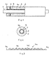
- Fig. 1 shows a conduit according to the teachings of the invention, which is shown in section in the left half.
- the conduit consists of a medium pipe 1, for example of steel, which is arranged concentrically in a jacket tube 2, for example made of plastic.
- the 3 is a heat-insulating body, which is arranged between the medium pipe 1 and the jacket tube 2.
- a band-shaped enclosure 4 which consists of panels 4a, which are filled with powdery material.
- the panels are still evacuated.
- the powdery material used is preferably powdery, amorphous silica, which is also referred to as highly dispersive silica.
- the band-shaped sheath 4 consists of several panels 4a, which are formed around the medium pipe 1 with overlapping strip edges. The overlapping strip edges are glued or welded together.
- Each panel 4a has a length of about 0.50 to 1.0 m.
- the panels 4 a are placed tightly against the medium pipe 1.
- the wall of each panel 4a is made of a plastic-coated aluminum foil, so that a vacuum can be maintained within the panels 4a over as long a period as possible.
- a curing agent In addition to the silicic acid, a curing agent, a clouding agent and fiber material may be present in the interior of each panel 4a.
- the wall thickness of the panels 4a is about 10 to 20 mm.
- Figure 2 shows a section through the conduit of Figure 1.
- the band-shaped enclosure 4 and the panels 4a has a plurality of extending in the longitudinal direction of the medium pipe 1 chambers 4b.
- FIG. 3 shows a panel 4a in the flat laid-out state. It can be seen the individual chambers 4b, which are filled with the silica and the other materials and evacuated.
- the wall of the panels 4a consists of a plastic-coated aluminum foil.
- a copolymer of the polyethylene is preferably used.
- the longitudinal edges 4c can be bonded together by supplying heat.
- At least one of the longitudinal edges 4c of the panels 4a is double-walled, d. H.
- d. H Here are two layers of plastic-coated aluminum foil stacked and glued or welded together.
- the two layers of plastic-coated aluminum foil are also glued together.
- the trapezoidal cross-section of the chambers 4b is maintained in that, in addition to the silicon dioxide, a curing agent which bonds the silicon dioxide powder is also contained within the chambers 4b.
Abstract
Description
- Die Erfindung betrifft ein vorgefertigtes wärmeisoliertes Leitungsrohr nach dem Oberbegriff des Anspruchs 1 sowie ein Verfahren zur Herstellung eines solchen Leitungsrohres nach dem Oberbegriff des Anspruchs 12.
- Es sind werkseitig vorgefertigte wärmeisolierte Leitungsrohre für die direkte Erdverlegung, Freiverlegung und Verlegung in Gebäuden, insbesondere für den Transport von erwärmten oder gekühlten Medien bekannt, welche am Verlegeort miteinander verbunden werden.
- Fernwärmerohre zu diesem Zweck sind beispielsweise in der CH-PS 410559 und der CH-PS 434910 beschrieben. Sie bestehen aus einem Mediumrohr aus Metall, welches koaxial mit Zwischenraum in einem nahtlosen Mantelrohr aus Polyethylen verläuft. Zur Wärmedämmung ist der Zwischenraum zwischen den beiden Rohren werksseitig mit einem in diesem Zwischenraum verschäumten Polyurethankörper ausgefüllt, welcher aufgrund einer Verklebung mit dem Mediumrohr und dem Mantelrohr eine Einheit mit diesen bildet. Derartige Leitungsrohre werden in der Fachwelt als Kunststoffmantelrohre bezeichnet.
- Der Vorteil dieser bekannten Rohre liegt darin, daß diese kostengünstig herstellbar sind. Ein Nachteil besteht darin, daß die Kosten bei der Verlegung sehr hoch zu Buche schlagen und daß die Verbindungsstellen oft nicht fachgerecht ausgeführt werden und es dann zu einem Feuchtigkeitseinbruch kommen kann.
- Ein weiterer Nachteil besteht darin, daß der bei Kunststoffmantelrohren verwendete Polyurethanschaum vielfach nicht die gewünschten Dämmwerte aufweist, sodaß die Wanddicke der Wärmedämmschicht erhöht werden muß, damit der geforderten Dämmwerte erreicht werden. Weiterhin ist nachteilig, daß die Standfestigkeit bzw. Beständigkeit des Polyurethanschaums bei Temperaturen oberhalb von 130 °C abnimmt, sodaß Medien mit einer Temperatur oberhalb von 130 °C mit Kunststoffmantelrohren nicht mehr transportiert werden können, weil dann im Laufe der Jahre Schäden sowohl in der Dämmschicht als auch bei den Mantelrohren aus Polyethylen auftreten können.
- Aus dem DE-GM 9 214 160 ist zur Behebung dieser Nachteile vorgeschlagen worden, zwischen dem Mediumrohr und dem Schaumstoffkörper eine Kernisolierung aus einem hitzebeständigen Material vorzusehen. Nach einer Ausgestaltung der Kernisolierung besteht diese aus einem Rohr aus Keramikfasern, beispielsweise aus Aluminiumsilikat. Die Dicke des Rohres aus Keramikfasern ist so bemessen, daß an der Grenzfläche Kernisolierung/Wärmedämmkörper eine Temperatur von 125 °C nicht überschritten wird.
- Der vorliegenden Erfindung liegt die Aufgabe zugrunde, ein wärmeisoliertes Leitungsrohr der eingangs erwähnten Art dahingehend zu verbessern, daß gegenüber einer einheitlichen Schicht aus Polyurethan ein wesentlich höherer Dämmwert des isolierten Leitungsrohres erzielt wird.
- Diese Aufgabe wird durch die im Kennzeichen des Anspruchs 1 erfaßten Merkmale bzw. die kennzeichnenden Merkmale des Anspruchs 12 gelöst.
- Der wesentliche Vorteil der Erfindung ist darin zu sehen, daß der Dämmwert der bandförmigen Umhüllung aufgrund der Kombination von pulvrigem Material und Vakuum extrem niedrig ist und somit die Wanddicke des Wärmedämmkörpers herabgesetzt werden kann. Die die Umhüllung bildenden Paneelen sind in sich geschlossene Behältnisse, in welchen das pulvrige Material befindlich ist und welche evakuiert sind. Auf diese Weise lassen sich extrem hohe Wärmedämmwerte erzielen.
- Weitere vorteilhafte Ausgestaltungen der Erfindung sind in den Unteransprüchen erfaßt.
- Die Erfindung ist anhand der in den Figuren 1, 2 und 3 schematisch dargestellten Ausführungsbeispiele näher erläutert.
- Die Fig. 1 zeigt ein Leitungsrohr nach der Lehre der Erfindung, welches in der linken Hälfte im Schnitt dargestellt ist.
- Das Leitungsrohr besteht aus einem Mediumrohr 1, beispielsweise aus Stahl, welches konzentrisch in einem Mantelrohr 2, beispielsweise aus Kunststoff angeordnet ist.
- Mit 3 ist ein Wärmedämmkörper bezeichnet, der zwischen dem Mediumrohr 1 und dem Mantelrohr 2 angeordnet ist.
- Auf dem Mediumrohr 1 ist eine bandförmige Umhüllung 4 angeordnet, die aus Paneelen 4a besteht, welche mit pulvrigem Material gefüllt sind. Zusätzlich sind die Paneelen noch evakuiert. Als pulvriges Material wird bevorzugt pulvriges, amorphes Siliziumdioxid verwendet, welches auch als hochdispersive Kieselsäure bezeichnet wird.
- Auf der bandförmigen Umhüllung 4 sitz noch ein Abstandshalter 5.
- Wie oben bereits erwähnt, besteht die bandförmige Umhüllung 4 aus mehreren Paneelen 4a, die um das Mediumrohr 1 mit überlappenden Bandkanten herumgeformt werden. Die überlappenden Bandkanten werden miteinander verklebt oder verschweißt. Jede Paneele 4a hat eine Länge von ca. 0,50 bis 1,0 m. Die Paneelen 4a werden dicht an dicht auf das Mediumrohr 1 aufgelegt. Die Wandung jeder Paneele 4a besteht aus einer kunststoffbeschichteten Aluminiumfolie, damit innerhalb der Paneele 4a ein Vakuum über einen möglichst langen Zeitraum aufrechterhalten werden kann.
- Neben der Kieselsäure können im Innern jeder Paneele 4a noch ein Härtungsmittel, ein Trübungsmittel sowie Fasermaterial vorhanden sein.
- Die Wanddicke der Paneele 4a beträgt in etwa 10 bis 20 mm.
- Figur 2 zeigt einen Schnitt durch das Leitungsrohr nach Figur 1. Hier ist zu erkennen, daß die bandförmige Umhüllung 4 bzw. die Paneele 4a eine Vielzahl von in Längsrichtung des Mediumrohres 1 verlaufenden Kammern 4b aufweist.
- In Figur 3 ist eine Paneele 4a im flach ausgelegten Zustand gezeigt. Es sind die einzelnen Kammern 4b zu erkennen, die mit der Kieselsäure und den weiteren Materialien gefüllt sowie evakuiert sind. Die Wandung der Paneele 4a besteht aus einer kunststoffbeschichteten Aluminiumfolie. Als Kunststoff wird bevorzugt ein Copolymer des Polyethylens verwendet. Dadurch lassen sich die Längskanten 4c miteinander durch Wärmezufuhr verkleben.
- Zwischen den einzelnen Kammern 4b sind nicht näher bezeichnete V-förmige Freiräume vorgesehen, damit eine Formung der Paneele 4a um das Mediumrohr 1 problemlos durchgeführt werden kann.
- Zumindest eine der Längskanten 4c der Paneele 4a ist doppelwandig ausgebildet, d. h. hier sind zwei Lagen der kunststoffbeschichteten Aluminiumfolie übereinander angeordnet und miteinander verklebt oder verschweißt. Am Fuß 4d der V-förmigen Freiräume sind die beiden Lagen der kunststoffbeschichteten Aluminiumfolie ebenfalls miteinander verklebt.
- Der trapezförmige Querschnitt der Kammern 4b bleibt dadurch erhalten, daß sich neben dem Siliziumdioxid noch ein das Siliziumdioxidpulver verklebendes Härtungsmittel innerhalb der Kammern 4b befindet.
- Die Herstellung des in den Figuren 1 und 2 schematisch dargestellten Leitungsrohres läuft wie folgt ab:
- Zunächst wird ein Mediumrohr 1 z. B. mit einer Länge von 6 bis 10 m bereitgestellt. Auf das Mediumrohr wird dann eine erste Paneele 4a herumgelegt, und die überlappenden Bandkanten 4c werden miteinander verklebt. Sodann wird in gleicher Weise eine zweite Paneele direkt an die erste Paneele anschließend um das Mediumrohr 1 herumgelegt und die Bandkanten miteinander verklebt. Weitere Paneelen werden in gleicher Weise auf das Mediumrohr 1 aufgelegt. Die Rohrenden bleiben frei. Das mit den Paneelen versehene Mediumrohr 1 wird dann in ein Kunststoffrohr 2 eingeführt und durch einen oder mehrere Abstandhalter 5 in konzentrischer Lage zum Kunststoffrohr 2 gehalten. Der zwischen Mediumrohr 1 und Kunststoffrohr 2 befindliche Ringraum wird dann in an sich bekannter Weise mit Polyurethanschaum oder Polyisocyanuratschaum ausgeschäumt.
Claims (16)
- Vorgefertigtes wärmeisoliertes Leitungsrohr, bestehend aus einem Mediumrohr (1), das koaxial mit Zwischenraum in einem Mantelrohr (2) aus Kunststoff verläuft, wobei der Zwischenraum zwischen dem Mediumrohr (1) und dem Mantelrohr (2) einen in diesem Raum verschäumten Schaumstoffkörper (3) als Wärmedämmung enthält und zwischen dem Mediumrohr (1) und dem Schaumstoffkörper (3) eine Kernisolierung aus einem anorganischen hitzebeständigem Material vorgesehen ist, dadurch gekennzeichnet, daß die Kernisolierung aus einer bandförmigen Umhüllung (4) aus einem oder mehreren Paneelen (4a) besteht, welche mit einem körnigen oder pulverförmigen Material gefüllt sind und welche evakuiert sind.
- Leitungsrohr nach Anspruch 1, dadurch gekennzeichnet, daß die Paneelen (4a) mit pulvrigem, amorphem Siliziumdioxid gefüllt sind.
- Leitungsrohr nach Anspruch 1 oder 2, dadurch gekennzeichnet, daß neben körnigen oder pulverförmigen Material noch Härtungsmittel, Trübungsmittel sowie Fasern innerhalb der Paneelen (4a) vorhanden sind.
- Leitungsrohr nach einem der Ansprüche 1 oder 3, dadurch gekennzeichnet, daß das amorphe Siliziumdioxid als pyrogene bzw. hochdispersive Kieselsäure vorliegt.
- Leitungsrohr nach einem der Ansprüche 1 bis 4, dadurch gekennzeichnet, daß die bandförmige Umhüllung (4) eine Vielzahl von in Längsrichtung des Mediumrohres (1) verlaufenden Kammern (4b) aufweist, in welchen sich das Siliziumdioxid befindet.
- Leitungsrohr nach einem der Ansprüche 1 bis 5, dadurch gekennzeichnet, daß die Wandung der bandförmigen Umhüllung (4) aus einer kunststoffbeschichteten Aluminiumfolie besteht.
- Leitungsrohr nach einem der Ansprüche 1 bis 6, dadurch gekennzeichnet, daß die bandförmige Umhüllung (4) mit in Längsrichtung des Mediumrohres (1) verlaufendem Schlitz das Mediumrohr (1) umhüllt.
- Leitungsrohr nach Anspruch 7, dadurch gekennzeichnet, daß die Längskanten (4c) der bandförmigen Umhüllung (4) einander überlappen.
- Leitungsrohr nach einem der Ansprüche 1 bis 8, dadurch gekennzeichnet, daß die Wanddicke der bandförmigen Umhüllung (4) zwischen 5 mm - 25 mm liegt.
- Leitungsrohr nach einem der Ansprüche 1 bis 9, dadurch gekennzeichnet, daß die bandförmige Umwicklung (4) aus einzelnen Paneelen (4a) mit jeweils einer Länge von 0,50 bis 1,00 m besteht.
- Leitungsrohr nach einem der Ansprüche 1 bis 10, dadurch gekennzeichnet, daß auf der bandförmigen Umhüllung (4) in bestimmten Abständen Abstandshalter (5) vorgesehen sind, welche das Mediumrohr (1) konzentrisch zum Mantelrohr (2) halten.
- Verfahren zur Herstellung eines vorgefertigten wärmeisolierten Leitungsrohres, bestehen aus einem Mediumrohr, das koaxial mit Zwischenraum in einem Mantelrohr aus Kunststoff verläuft, wobei der Zwischenraum zwischen dem Mediumrohr und dem Mantelrohr einen in diesem Raum verschäumten Schaumstoffkörper als Wärmedämmung enthält und zwischen dem Mediumrohr und dem Schaumstoffkörper eine Kernisolierung aus einem anorganischen, hitzebeständigen Material vorgesehen ist, dadurch gekennzeichnet, daß auf das Mediumrohr eine bandförmige Umhüllung aufgelegt wird, die aus einem Paneel besteht, in welchem ein körniges oder pulverförmiges Material befindlich ist und welches evakuiert ist, daß auf die bandförmige Umhüllung Abstandshalter aufgebracht werden, daß das mit der bandförmigen Umhüllung und den Abstandshaltern versehene Mediumrohr in ein Mantelrohr eingeführt wird und daß der Ringspalt zwischen der bandförmigen Umhüllung und dem Mantelrohr ausgeschäumt wird.
- Verfahren nach Anspruch 12, daß der Ringspalt mit einem Schaumstoff auf der Basis von Polyurethan oder Polyisocyanurat ausgeschäumt wird.
- Verfahren nach einem der Ansprüche 11 bis 13, dadurch gekennzeichnet, daß die bandförmige Umhüllung in Form mehrerer hintereinander liegender Paneele mit in Längsrichtung des Mediumrohres verlaufenden Längsschlitz auf das Mediumrohr aufgelegt wird.
- Verfahren nach einem der Ansprüche 11 bis 14, dadurch gekennzeichnet, daß die Längskanten des Paneels einander überlappend miteinander verklebt werden.
- Verfahren nach einem der Ansprüche 11 bis 14, dadurch gekennzeichnet, daß die Längskanten der bandförmigen Umhüllung mit einem Klebeband fixiert werden.
Priority Applications (6)
| Application Number | Priority Date | Filing Date | Title |
|---|---|---|---|
| EP04015597A EP1612468B1 (de) | 2004-07-02 | 2004-07-02 | Leitungsrohr |
| PL04015597T PL1612468T3 (pl) | 2004-07-02 | 2004-07-02 | Rura przewodowa |
| DE502004003141T DE502004003141D1 (de) | 2004-07-02 | 2004-07-02 | Leitungsrohr |
| DK04015597T DK1612468T3 (da) | 2004-07-02 | 2004-07-02 | Ledningsrör |
| AT04015597T ATE356312T1 (de) | 2004-07-02 | 2004-07-02 | Leitungsrohr |
| PL375968A PL375968A1 (pl) | 2004-07-02 | 2005-06-29 | Rura przewodowa |
Applications Claiming Priority (1)
| Application Number | Priority Date | Filing Date | Title |
|---|---|---|---|
| EP04015597A EP1612468B1 (de) | 2004-07-02 | 2004-07-02 | Leitungsrohr |
Publications (2)
| Publication Number | Publication Date |
|---|---|
| EP1612468A1 true EP1612468A1 (de) | 2006-01-04 |
| EP1612468B1 EP1612468B1 (de) | 2007-03-07 |
Family
ID=34925593
Family Applications (1)
| Application Number | Title | Priority Date | Filing Date |
|---|---|---|---|
| EP04015597A Not-in-force EP1612468B1 (de) | 2004-07-02 | 2004-07-02 | Leitungsrohr |
Country Status (5)
| Country | Link |
|---|---|
| EP (1) | EP1612468B1 (de) |
| AT (1) | ATE356312T1 (de) |
| DE (1) | DE502004003141D1 (de) |
| DK (1) | DK1612468T3 (de) |
| PL (2) | PL1612468T3 (de) |
Cited By (2)
| Publication number | Priority date | Publication date | Assignee | Title |
|---|---|---|---|---|
| WO2012002834A1 (ru) | 2010-06-28 | 2012-01-05 | Общество С Ограниченной Ответственностью "Cmиt-Яpцebo" | Способ изготовления теплоизолированной гибкой трубы |
| WO2012039638A1 (ru) | 2010-09-20 | 2012-03-29 | Общество С Ограниченной Ответственностью "Cmиt-Яpцebo" | Линия для изготовления теплоизолированной гибкой трубы |
Families Citing this family (1)
| Publication number | Priority date | Publication date | Assignee | Title |
|---|---|---|---|---|
| CN114321511B (zh) * | 2021-12-14 | 2024-01-09 | 临海伟星新型建材有限公司 | 一种毛细管缠绕保温塑料管道及其制备方法 |
Citations (9)
| Publication number | Priority date | Publication date | Assignee | Title |
|---|---|---|---|---|
| CH410559A (de) | 1963-08-30 | 1966-03-31 | Meier Schenk Arthur | Isolierrohr und Verfahren zu dessen Herstellung |
| CH434910A (de) | 1963-11-13 | 1967-04-30 | Meier Schenk Arthur | Isolierrohr |
| EP0440031A1 (de) * | 1990-01-12 | 1991-08-07 | Nisshinbo Industries, Inc. | Gegen Wärme vakuumisolierter Behälter |
| DE9214160U1 (de) | 1992-10-20 | 1992-12-17 | Pan-Isovit Holding Ag, Pfaeffikon, Ch | |
| US5843353A (en) * | 1995-04-13 | 1998-12-01 | Imperial Chemical Industries Plc | Non-planar evacuated insulation panels and a method for making same |
| WO2000031459A1 (de) * | 1998-11-20 | 2000-06-02 | Mi Developments Austria Ag & Co Kg | Rohrförmige konstruktion |
| US6110310A (en) * | 1998-02-19 | 2000-08-29 | Wacker-Chemie Gmbh | Panel-shaped, evacuated molded element, method of thermal insulation and use of the molded element |
| DE19914963A1 (de) * | 1999-04-01 | 2000-10-05 | Isovac Ingenieurgesellschaft M | Vakuumisolationspaneel |
| WO2003098094A1 (en) * | 2002-05-21 | 2003-11-27 | Saes Getters S.P.A. | Thermoinsulating system |
-
2004
- 2004-07-02 EP EP04015597A patent/EP1612468B1/de not_active Not-in-force
- 2004-07-02 AT AT04015597T patent/ATE356312T1/de not_active IP Right Cessation
- 2004-07-02 DK DK04015597T patent/DK1612468T3/da active
- 2004-07-02 PL PL04015597T patent/PL1612468T3/pl unknown
- 2004-07-02 DE DE502004003141T patent/DE502004003141D1/de not_active Expired - Fee Related
-
2005
- 2005-06-29 PL PL375968A patent/PL375968A1/pl unknown
Patent Citations (9)
| Publication number | Priority date | Publication date | Assignee | Title |
|---|---|---|---|---|
| CH410559A (de) | 1963-08-30 | 1966-03-31 | Meier Schenk Arthur | Isolierrohr und Verfahren zu dessen Herstellung |
| CH434910A (de) | 1963-11-13 | 1967-04-30 | Meier Schenk Arthur | Isolierrohr |
| EP0440031A1 (de) * | 1990-01-12 | 1991-08-07 | Nisshinbo Industries, Inc. | Gegen Wärme vakuumisolierter Behälter |
| DE9214160U1 (de) | 1992-10-20 | 1992-12-17 | Pan-Isovit Holding Ag, Pfaeffikon, Ch | |
| US5843353A (en) * | 1995-04-13 | 1998-12-01 | Imperial Chemical Industries Plc | Non-planar evacuated insulation panels and a method for making same |
| US6110310A (en) * | 1998-02-19 | 2000-08-29 | Wacker-Chemie Gmbh | Panel-shaped, evacuated molded element, method of thermal insulation and use of the molded element |
| WO2000031459A1 (de) * | 1998-11-20 | 2000-06-02 | Mi Developments Austria Ag & Co Kg | Rohrförmige konstruktion |
| DE19914963A1 (de) * | 1999-04-01 | 2000-10-05 | Isovac Ingenieurgesellschaft M | Vakuumisolationspaneel |
| WO2003098094A1 (en) * | 2002-05-21 | 2003-11-27 | Saes Getters S.P.A. | Thermoinsulating system |
Cited By (2)
| Publication number | Priority date | Publication date | Assignee | Title |
|---|---|---|---|---|
| WO2012002834A1 (ru) | 2010-06-28 | 2012-01-05 | Общество С Ограниченной Ответственностью "Cmиt-Яpцebo" | Способ изготовления теплоизолированной гибкой трубы |
| WO2012039638A1 (ru) | 2010-09-20 | 2012-03-29 | Общество С Ограниченной Ответственностью "Cmиt-Яpцebo" | Линия для изготовления теплоизолированной гибкой трубы |
Also Published As
| Publication number | Publication date |
|---|---|
| EP1612468B1 (de) | 2007-03-07 |
| ATE356312T1 (de) | 2007-03-15 |
| PL375968A1 (pl) | 2006-01-09 |
| DK1612468T3 (da) | 2007-07-02 |
| DE502004003141D1 (de) | 2007-04-19 |
| PL1612468T3 (pl) | 2007-07-31 |
Similar Documents
| Publication | Publication Date | Title |
|---|---|---|
| EP0952382B1 (de) | Flexibles Leitungsrohr | |
| DE1525658C3 (de) | Wärmeisoliertes Leitungsrohr | |
| EP0896184B2 (de) | Dämm-Ummantelung für Rohre | |
| CH660907A5 (de) | Waermeisoliertes leitungsrohr und verfahren zu seiner herstellung. | |
| EP0892207B1 (de) | Wärmeisoliertes Leitungsrohr | |
| EP0044468B1 (de) | Wärmeisoliertes Rohrleitungselement und Rohrleitungssystem aus diesen Rohrleitungselementen sowie Verfahren zur Herstellung des Rohrleitungselementes und des Rohrleitungssystems | |
| DE3635515C2 (de) | Wärmeisoliertes Leitungsrohr | |
| DE10211074A1 (de) | Leitungsrohr für den Transport von tiefgekühlten Medien | |
| EP0017254A1 (de) | Wärmegedämmtes Rohr und Verfahren zu seiner Herstellung | |
| EP1612468B1 (de) | Leitungsrohr | |
| CH664205A5 (de) | Waermeisoliertes leitungsrohr. | |
| DE202019004158U1 (de) | Isoliertes Rohr | |
| CH673694A5 (de) | ||
| DE3018781A1 (de) | Thermisch isoliertes leitungsrohr | |
| EP0459973A1 (de) | Isoliertes Rohr sowie Verfahren zum Herstellen desselben | |
| EP1208962B1 (de) | Verfahren zur kontinuierlichen Herstellung eines wenigstens drei Lagen aufweisenden Isolierschlauchs | |
| DE2518940A1 (de) | Rohrleitungsisolierung | |
| EP1457729A1 (de) | Abstandshalter für ein langgestrecktes Substrat | |
| AT401098B (de) | Isoliertes rohr sowie verfahren zu seiner herstellung | |
| DE4314761C1 (de) | Verfahren zum Herstellen einzelner Leitungsabschnitte einer Molchleitung | |
| EP1124085B1 (de) | Flexibles Leitungsrohr | |
| DE2340077A1 (de) | Rohrleitung zum transport fluessiger oder gasfoermiger erwaermter oder gekuehlter medien | |
| EP0165387A1 (de) | Kombinierte Leitung aus Kunststoffrohren | |
| DE3741083A1 (de) | Waermeisoliertes leitungsrohr | |
| DE2460954C3 (de) | Wassergekühltes Hochspannungsenergiekabel mit äußerer thermischer Isolation |
Legal Events
| Date | Code | Title | Description |
|---|---|---|---|
| PUAI | Public reference made under article 153(3) epc to a published international application that has entered the european phase |
Free format text: ORIGINAL CODE: 0009012 |
|
| 17P | Request for examination filed |
Effective date: 20041206 |
|
| AK | Designated contracting states |
Kind code of ref document: A1 Designated state(s): AT BE BG CH CY CZ DE DK EE ES FI FR GB GR HU IE IT LI LU MC NL PL PT RO SE SI SK TR |
|
| AX | Request for extension of the european patent |
Extension state: AL HR LT LV MK |
|
| AKX | Designation fees paid |
Designated state(s): AT BE BG CH CY CZ DE DK EE ES FI FR GB GR HU IE IT LI LU MC NL PL PT RO SE SI SK TR |
|
| GRAP | Despatch of communication of intention to grant a patent |
Free format text: ORIGINAL CODE: EPIDOSNIGR1 |
|
| GRAS | Grant fee paid |
Free format text: ORIGINAL CODE: EPIDOSNIGR3 |
|
| GRAA | (expected) grant |
Free format text: ORIGINAL CODE: 0009210 |
|
| AK | Designated contracting states |
Kind code of ref document: B1 Designated state(s): AT BE BG CH CY CZ DE DK EE ES FI FR GB GR HU IE IT LI LU MC NL PL PT RO SE SI SK TR |
|
| PG25 | Lapsed in a contracting state [announced via postgrant information from national office to epo] |
Ref country code: NL Free format text: LAPSE BECAUSE OF FAILURE TO SUBMIT A TRANSLATION OF THE DESCRIPTION OR TO PAY THE FEE WITHIN THE PRESCRIBED TIME-LIMIT Effective date: 20070307 Ref country code: SI Free format text: LAPSE BECAUSE OF FAILURE TO SUBMIT A TRANSLATION OF THE DESCRIPTION OR TO PAY THE FEE WITHIN THE PRESCRIBED TIME-LIMIT Effective date: 20070307 |
|
| REG | Reference to a national code |
Ref country code: GB Ref legal event code: FG4D Free format text: NOT ENGLISH |
|
| REG | Reference to a national code |
Ref country code: CH Ref legal event code: EP |
|
| REG | Reference to a national code |
Ref country code: CH Ref legal event code: NV Representative=s name: PA ALDO ROEMPLER |
|
| REF | Corresponds to: |
Ref document number: 502004003141 Country of ref document: DE Date of ref document: 20070419 Kind code of ref document: P |
|
| REG | Reference to a national code |
Ref country code: IE Ref legal event code: FG4D Free format text: LANGUAGE OF EP DOCUMENT: GERMAN |
|
| REG | Reference to a national code |
Ref country code: SE Ref legal event code: TRGR |
|
| REG | Reference to a national code |
Ref country code: HU Ref legal event code: AG4A Ref document number: E001464 Country of ref document: HU |
|
| PG25 | Lapsed in a contracting state [announced via postgrant information from national office to epo] |
Ref country code: ES Free format text: LAPSE BECAUSE OF FAILURE TO SUBMIT A TRANSLATION OF THE DESCRIPTION OR TO PAY THE FEE WITHIN THE PRESCRIBED TIME-LIMIT Effective date: 20070618 |
|
| REG | Reference to a national code |
Ref country code: DK Ref legal event code: T3 |
|
| PGFP | Annual fee paid to national office [announced via postgrant information from national office to epo] |
Ref country code: HU Payment date: 20070711 Year of fee payment: 4 |
|
| REG | Reference to a national code |
Ref country code: PL Ref legal event code: T3 |
|
| PG25 | Lapsed in a contracting state [announced via postgrant information from national office to epo] |
Ref country code: PT Free format text: LAPSE BECAUSE OF FAILURE TO SUBMIT A TRANSLATION OF THE DESCRIPTION OR TO PAY THE FEE WITHIN THE PRESCRIBED TIME-LIMIT Effective date: 20070807 |
|
| NLV1 | Nl: lapsed or annulled due to failure to fulfill the requirements of art. 29p and 29m of the patents act | ||
| ET | Fr: translation filed | ||
| GBV | Gb: ep patent (uk) treated as always having been void in accordance with gb section 77(7)/1977 [no translation filed] |
Effective date: 20070307 |
|
| PG25 | Lapsed in a contracting state [announced via postgrant information from national office to epo] |
Ref country code: SK Free format text: LAPSE BECAUSE OF FAILURE TO SUBMIT A TRANSLATION OF THE DESCRIPTION OR TO PAY THE FEE WITHIN THE PRESCRIBED TIME-LIMIT Effective date: 20070307 Ref country code: GB Free format text: LAPSE BECAUSE OF FAILURE TO SUBMIT A TRANSLATION OF THE DESCRIPTION OR TO PAY THE FEE WITHIN THE PRESCRIBED TIME-LIMIT Effective date: 20070307 |
|
| PGFP | Annual fee paid to national office [announced via postgrant information from national office to epo] |
Ref country code: FI Payment date: 20070730 Year of fee payment: 4 |
|
| REG | Reference to a national code |
Ref country code: IE Ref legal event code: FD4D |
|
| PG25 | Lapsed in a contracting state [announced via postgrant information from national office to epo] |
Ref country code: RO Free format text: LAPSE BECAUSE OF FAILURE TO SUBMIT A TRANSLATION OF THE DESCRIPTION OR TO PAY THE FEE WITHIN THE PRESCRIBED TIME-LIMIT Effective date: 20070307 |
|
| PLBE | No opposition filed within time limit |
Free format text: ORIGINAL CODE: 0009261 |
|
| STAA | Information on the status of an ep patent application or granted ep patent |
Free format text: STATUS: NO OPPOSITION FILED WITHIN TIME LIMIT |
|
| BERE | Be: lapsed |
Owner name: BRUGG ROHR AG, HOLDING Effective date: 20070731 |
|
| PG25 | Lapsed in a contracting state [announced via postgrant information from national office to epo] |
Ref country code: IE Free format text: LAPSE BECAUSE OF FAILURE TO SUBMIT A TRANSLATION OF THE DESCRIPTION OR TO PAY THE FEE WITHIN THE PRESCRIBED TIME-LIMIT Effective date: 20070307 |
|
| PGFP | Annual fee paid to national office [announced via postgrant information from national office to epo] |
Ref country code: CZ Payment date: 20070628 Year of fee payment: 4 Ref country code: SE Payment date: 20070719 Year of fee payment: 4 |
|
| 26N | No opposition filed |
Effective date: 20071210 |
|
| PG25 | Lapsed in a contracting state [announced via postgrant information from national office to epo] |
Ref country code: GR Free format text: LAPSE BECAUSE OF FAILURE TO SUBMIT A TRANSLATION OF THE DESCRIPTION OR TO PAY THE FEE WITHIN THE PRESCRIBED TIME-LIMIT Effective date: 20070608 Ref country code: MC Free format text: LAPSE BECAUSE OF NON-PAYMENT OF DUE FEES Effective date: 20070731 |
|
| PGFP | Annual fee paid to national office [announced via postgrant information from national office to epo] |
Ref country code: FR Payment date: 20070718 Year of fee payment: 4 |
|
| PG25 | Lapsed in a contracting state [announced via postgrant information from national office to epo] |
Ref country code: BE Free format text: LAPSE BECAUSE OF NON-PAYMENT OF DUE FEES Effective date: 20070731 |
|
| REG | Reference to a national code |
Ref country code: CH Ref legal event code: PCAR Free format text: ALDO ROEMPLER PATENTANWALT;BRENDENWEG 11 POSTFACH 154;9424 RHEINECK (CH) |
|
| PGFP | Annual fee paid to national office [announced via postgrant information from national office to epo] |
Ref country code: CH Payment date: 20080730 Year of fee payment: 5 Ref country code: DE Payment date: 20080729 Year of fee payment: 5 Ref country code: DK Payment date: 20080724 Year of fee payment: 5 |
|
| PGFP | Annual fee paid to national office [announced via postgrant information from national office to epo] |
Ref country code: AT Payment date: 20080725 Year of fee payment: 5 Ref country code: IT Payment date: 20080724 Year of fee payment: 5 |
|
| PG25 | Lapsed in a contracting state [announced via postgrant information from national office to epo] |
Ref country code: EE Free format text: LAPSE BECAUSE OF FAILURE TO SUBMIT A TRANSLATION OF THE DESCRIPTION OR TO PAY THE FEE WITHIN THE PRESCRIBED TIME-LIMIT Effective date: 20070307 |
|
| EUG | Se: european patent has lapsed | ||
| PG25 | Lapsed in a contracting state [announced via postgrant information from national office to epo] |
Ref country code: HU Free format text: LAPSE BECAUSE OF NON-PAYMENT OF DUE FEES Effective date: 20080703 |
|
| REG | Reference to a national code |
Ref country code: FR Ref legal event code: ST Effective date: 20090331 |
|
| PG25 | Lapsed in a contracting state [announced via postgrant information from national office to epo] |
Ref country code: FI Free format text: LAPSE BECAUSE OF NON-PAYMENT OF DUE FEES Effective date: 20080702 Ref country code: CZ Free format text: LAPSE BECAUSE OF NON-PAYMENT OF DUE FEES Effective date: 20080702 |
|
| PG25 | Lapsed in a contracting state [announced via postgrant information from national office to epo] |
Ref country code: CY Free format text: LAPSE BECAUSE OF FAILURE TO SUBMIT A TRANSLATION OF THE DESCRIPTION OR TO PAY THE FEE WITHIN THE PRESCRIBED TIME-LIMIT Effective date: 20070307 |
|
| PG25 | Lapsed in a contracting state [announced via postgrant information from national office to epo] |
Ref country code: LU Free format text: LAPSE BECAUSE OF NON-PAYMENT OF DUE FEES Effective date: 20070702 Ref country code: BG Free format text: LAPSE BECAUSE OF FAILURE TO SUBMIT A TRANSLATION OF THE DESCRIPTION OR TO PAY THE FEE WITHIN THE PRESCRIBED TIME-LIMIT Effective date: 20070607 Ref country code: FR Free format text: LAPSE BECAUSE OF NON-PAYMENT OF DUE FEES Effective date: 20080731 |
|
| PG25 | Lapsed in a contracting state [announced via postgrant information from national office to epo] |
Ref country code: TR Free format text: LAPSE BECAUSE OF FAILURE TO SUBMIT A TRANSLATION OF THE DESCRIPTION OR TO PAY THE FEE WITHIN THE PRESCRIBED TIME-LIMIT Effective date: 20070307 |
|
| PGFP | Annual fee paid to national office [announced via postgrant information from national office to epo] |
Ref country code: PL Payment date: 20090828 Year of fee payment: 6 |
|
| REG | Reference to a national code |
Ref country code: CH Ref legal event code: PL |
|
| REG | Reference to a national code |
Ref country code: DK Ref legal event code: EBP |
|
| PG25 | Lapsed in a contracting state [announced via postgrant information from national office to epo] |
Ref country code: LI Free format text: LAPSE BECAUSE OF NON-PAYMENT OF DUE FEES Effective date: 20090731 Ref country code: CH Free format text: LAPSE BECAUSE OF NON-PAYMENT OF DUE FEES Effective date: 20090731 |
|
| PG25 | Lapsed in a contracting state [announced via postgrant information from national office to epo] |
Ref country code: AT Free format text: LAPSE BECAUSE OF NON-PAYMENT OF DUE FEES Effective date: 20090702 Ref country code: DE Free format text: LAPSE BECAUSE OF NON-PAYMENT OF DUE FEES Effective date: 20100202 |
|
| PG25 | Lapsed in a contracting state [announced via postgrant information from national office to epo] |
Ref country code: DK Free format text: LAPSE BECAUSE OF NON-PAYMENT OF DUE FEES Effective date: 20090731 Ref country code: SE Free format text: LAPSE BECAUSE OF NON-PAYMENT OF DUE FEES Effective date: 20080703 |
|
| PG25 | Lapsed in a contracting state [announced via postgrant information from national office to epo] |
Ref country code: IT Free format text: LAPSE BECAUSE OF NON-PAYMENT OF DUE FEES Effective date: 20090702 |
|
| REG | Reference to a national code |
Ref country code: PL Ref legal event code: LAPE |
|
| PG25 | Lapsed in a contracting state [announced via postgrant information from national office to epo] |
Ref country code: PL Free format text: LAPSE BECAUSE OF NON-PAYMENT OF DUE FEES Effective date: 20100702 |