EP1612450A2 - Seilverstelleinrichtung - Google Patents
Seilverstelleinrichtung Download PDFInfo
- Publication number
- EP1612450A2 EP1612450A2 EP05010285A EP05010285A EP1612450A2 EP 1612450 A2 EP1612450 A2 EP 1612450A2 EP 05010285 A EP05010285 A EP 05010285A EP 05010285 A EP05010285 A EP 05010285A EP 1612450 A2 EP1612450 A2 EP 1612450A2
- Authority
- EP
- European Patent Office
- Prior art keywords
- adjuster
- cord
- bar
- set forth
- wall
- Prior art date
- Legal status (The legal status is an assumption and is not a legal conclusion. Google has not performed a legal analysis and makes no representation as to the accuracy of the status listed.)
- Ceased
Links
- 238000000034 method Methods 0.000 claims 6
- 230000002708 enhancing effect Effects 0.000 claims 2
- 238000005299 abrasion Methods 0.000 claims 1
- 238000000465 moulding Methods 0.000 claims 1
- 230000000452 restraining effect Effects 0.000 claims 1
Images




Classifications
-
- A—HUMAN NECESSITIES
- A44—HABERDASHERY; JEWELLERY
- A44B—BUTTONS, PINS, BUCKLES, SLIDE FASTENERS, OR THE LIKE
- A44B11/00—Buckles; Similar fasteners for interconnecting straps or the like, e.g. for safety belts
- A44B11/02—Buckles; Similar fasteners for interconnecting straps or the like, e.g. for safety belts frictionally engaging surface of straps
- A44B11/18—Strap held by threading through linked rings
-
- F—MECHANICAL ENGINEERING; LIGHTING; HEATING; WEAPONS; BLASTING
- F16—ENGINEERING ELEMENTS AND UNITS; GENERAL MEASURES FOR PRODUCING AND MAINTAINING EFFECTIVE FUNCTIONING OF MACHINES OR INSTALLATIONS; THERMAL INSULATION IN GENERAL
- F16G—BELTS, CABLES, OR ROPES, PREDOMINANTLY USED FOR DRIVING PURPOSES; CHAINS; FITTINGS PREDOMINANTLY USED THEREFOR
- F16G11/00—Means for fastening cables or ropes to one another or to other objects; Caps or sleeves for fixing on cables or ropes
- F16G11/10—Quick-acting fastenings; Clamps holding in one direction only
- F16G11/103—Quick-acting fastenings; Clamps holding in one direction only deforming the cable by bending it around or inserting it into the fastener
-
- Y—GENERAL TAGGING OF NEW TECHNOLOGICAL DEVELOPMENTS; GENERAL TAGGING OF CROSS-SECTIONAL TECHNOLOGIES SPANNING OVER SEVERAL SECTIONS OF THE IPC; TECHNICAL SUBJECTS COVERED BY FORMER USPC CROSS-REFERENCE ART COLLECTIONS [XRACs] AND DIGESTS
- Y10—TECHNICAL SUBJECTS COVERED BY FORMER USPC
- Y10T—TECHNICAL SUBJECTS COVERED BY FORMER US CLASSIFICATION
- Y10T24/00—Buckles, buttons, clasps, etc.
- Y10T24/39—Cord and rope holders
- Y10T24/3916—One-piece
-
- Y—GENERAL TAGGING OF NEW TECHNOLOGICAL DEVELOPMENTS; GENERAL TAGGING OF CROSS-SECTIONAL TECHNOLOGIES SPANNING OVER SEVERAL SECTIONS OF THE IPC; TECHNICAL SUBJECTS COVERED BY FORMER USPC CROSS-REFERENCE ART COLLECTIONS [XRACs] AND DIGESTS
- Y10—TECHNICAL SUBJECTS COVERED BY FORMER USPC
- Y10T—TECHNICAL SUBJECTS COVERED BY FORMER US CLASSIFICATION
- Y10T24/00—Buckles, buttons, clasps, etc.
- Y10T24/40—Buckles
- Y10T24/4002—Harness
- Y10T24/4012—Clamping
- Y10T24/4014—One-piece
-
- Y—GENERAL TAGGING OF NEW TECHNOLOGICAL DEVELOPMENTS; GENERAL TAGGING OF CROSS-SECTIONAL TECHNOLOGIES SPANNING OVER SEVERAL SECTIONS OF THE IPC; TECHNICAL SUBJECTS COVERED BY FORMER USPC CROSS-REFERENCE ART COLLECTIONS [XRACs] AND DIGESTS
- Y10—TECHNICAL SUBJECTS COVERED BY FORMER USPC
- Y10T—TECHNICAL SUBJECTS COVERED BY FORMER US CLASSIFICATION
- Y10T24/00—Buckles, buttons, clasps, etc.
- Y10T24/40—Buckles
- Y10T24/4088—One-piece
-
- Y—GENERAL TAGGING OF NEW TECHNOLOGICAL DEVELOPMENTS; GENERAL TAGGING OF CROSS-SECTIONAL TECHNOLOGIES SPANNING OVER SEVERAL SECTIONS OF THE IPC; TECHNICAL SUBJECTS COVERED BY FORMER USPC CROSS-REFERENCE ART COLLECTIONS [XRACs] AND DIGESTS
- Y10—TECHNICAL SUBJECTS COVERED BY FORMER USPC
- Y10T—TECHNICAL SUBJECTS COVERED BY FORMER US CLASSIFICATION
- Y10T24/00—Buckles, buttons, clasps, etc.
- Y10T24/47—Strap-end-attaching devices
- Y10T24/4736—Buckle connected
Definitions
- the present invention relates generally to an adjuster and more particularly to a cord adjuster configured to adjust the position of a cord with respect to the adjuster.
- an adjuster is known in the art.
- Prior art adjusters are configured to work with a belt so as to adjust the position of the belt with respect to the adjuster and to hold the belt in position after it has been adjusted.
- such an adjuster is securely fastened on one end and includes a tortuous path configured to allow a belt to travel through the tortuous path.
- the belt is inserted through the tortuous path such that there is a first and second portion of the belt extending from the adjuster, each on opposite sides of the tortuous path. By pulling on the first portion, additional lengths of the belt can be pulled through the adjuster such that the length of the first portion is increased. Once a sufficient length of belt has been pulled through the adjuster, the second portion of the belt can be placed under tension.
- the resultant friction force created by the tortuous path is greater than the tension force such that the belt is prevented from being pulled through the adjuster, thereby holding the belt in place.
- the present invention is directed to an improved adjuster suitable for use with a cord.
- the adjuster has a first end that can be securely attached to a support surface.
- the adjuster includes a tortuous path.
- a cord can be inserted through the tortuous path so that a first end and a second end of the cord extend from the tortuous path.
- tension is applied to the second end of the cord, the design of the tortuous path creates a resultant friction force greater than the tension force.
- a length of cord can be inserted into a tortuous path of the adjuster and once the second end is under tension, the position of the cord relative to the adjuster can be maintained.
- the adjuster can be translated from a first position to a second position so that the friction forces due to the tortuous path are substantially reduced.
- the cord can then be pulled through the tortuous path by applying tension to either the first or the second end of the cord.
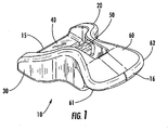
- FIG. 1 is an isometric view of an exemplary embodiment of an adjuster.
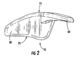
- FIG. 2 is a side view of the adjuster depicted in FIG. 1.
- FIG. 3 is a plan view of the adjuster depicted in FIG. 1.
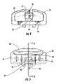
- FIG. 4 is a front view of the adjuster depicted in FIG. 1.
- FIG. 5 is a rear view of the adjuster depicted in FIG. 1.
- FIG. 6 is a rear view of alternative exemplary embodiment of an adjuster.
- FIG. 7 is an isometric view of an exemplary embodiment of an adjuster and cord.
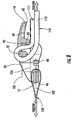
- FIG. 8 is a cross-sectional view of an exemplary embodiment of an adjuster and a cord in a first position, taken along the line 8-8 in FIG. 5.
- FIG. 9 is a cross-sectional view of the adjuster depicted in FIG. 8 in a second position.
- the adjuster 10 includes a first end 15 and a second end 16.
- the adjuster 10 further includes a first wall 20 and a second wall 30.
- Mounted between the first wall 20 and the second wall 30 is a first bar 40.
- the first bar 40 is located near the first end 15 of the adjuster 10 and is useful for providing an attachment point for a looping member such as a belt, cord, or the like. Other means of holding are also possible.
- the first bar 40 can be configured in a known manner so as to be constrained by some other retaining feature such as a hook or a latch.
- first bar 40 is to be constrained by a cord, it is preferable that the length of the first bar 40 is fairly close to the diameter of the cord or that the first bar 40 be curved so that forces exerted on the first bar 40 do not introduce undesirable moment forces on the adjuster 10.
- bar 40 may be replaced with two holes, one in wall 20 and one in wall 30, such that the cord extends left to right through the holes.
- a second bar 50 is also mounted between the first wall 20 and the second wall 30. As depicted, the second bar 50 is shorter than first bar 40. This allows the first wall 20 to be located closer to the second wall 30. In an embodiment, the space between the first wall 20 and the second wall 30 approximate the second bar 50 is similar to the diameter of the cord that is to be adjusted by the adjuster 10. Such an arrangement aids in ensuring the proper orientation of the cord when inserted into the adjuster 10.
- a tab 60 extends from the first and second walls 20, 30 to the second end 16 of the adjuster 10.
- a rear wall (not visible but shown as element 85 in FIG. 5) connects the first wall 20 to the second wall 30.
- tab 60 extends from the rear wall to the second end 16.
- the tab 60 provides a means for translating the adjuster 10 in a manner that will be more fully described below.
- the tab 60 includes rounded corners 61 and 62. While not required, the rounded corners 61, 62 help to make the adjuster 10 more ergonomic to the user so that the tab 60 is less likely to cause abrasions to materials or individuals that come into contact with the tab 60.
- FIG. 2 illustrates a side view of the adjuster depicted in FIG. 1.
- the adjuster 10 includes a bottom side 70 and a top side 75. As depicted, the bottom side 70 and the top side 75 are curved. The curvature of the top side 75 reduces potential abrasions that might otherwise be caused by rubbing against the top side 75. The curvature of the bottom side 70 can be beneficial in improving the interface between the adjuster 10 and the surface of the object being restrained. Of course, the adjuster 10 can also work in situations where the bottom surface 70 of the adjuster 10 is not resting against an object. In such a situation, the curvature of the bottom side 70 helps prevent undesirable abrasions that might otherwise be caused by contact with the adjuster 10.
- FIG. 3 a plan view of the adjuster depicted in FIG. 1 is provided.
- the first wall 20 and the second wall 30 are curved and are connected together by the first bar 40, the second bar 50, a keeper bar 80 and a rear wall 85.
- a trough 90 is provided in the rear wall 85.
- the keeper bar 80 helps direct the cord toward the trough 90 when tension is removed and then reapplied to a cord being positioned by the adjuster 10.
- the distance between the first wall 20 and the second wall 30 about the second bar 50 is substantially similar to the width of the trough 90.
- the walls 20, 30 help keep the cord properly positioned.
- a portion of the trough 90 could have a width less than the distance between the first wall 20 and the second wall 30 and also less than the diameter of the cord.
- FIG. 4 a front view of the adjuster depicted in FIG. 1 is provided.
- first bar 40 and second bar 50 join walls 20, 30 at two different elevations or horizontal planes.
- the upper edge 95 of trough 90 is at a third elevation or horizontal plane located between the first and second plane. The benefit of this arrangement will be discussed below.
- the second bar 50 can include a surface 51 with friction enhancing properties.
- the surface 51 of second bar 50 could include a number of angled surfaces (like a decagon, for instance) configured to aid in increasing the amount of frictional resistance to be exerted on the cord when installed. As not all areas of the second bar 50 come into contact with the cord while under tension, it may be desirable to configure the surface 51 so that only a portion of the surface 51 have friction enhancing properties.
- Other methods of enhancing the friction of the surface 51 such as the use of a rough surface or small projections are also possible, however the method of enhancing the coefficient of friction on surface 51 should be compliant with the type of cord used so as to avoid undesirable abrasion to, and premature wear of the cord during operation.
- FIG. 5 a rear view of the adjuster depicted in FIG. 1 is illustrated.
- the rear wall 85 joins the first wall 20 and the second wall 30.
- the trough 90 is formed by two side edges 93 and the upper edge 95.
- One advantage of providing the trough 90 in the rear wall 85 is that the cord can form a stacked arrangement in the trough 90.
- the dimension of the upper edge 95 is similar to or slightly larger than the diameter of the cord being positioned by the adjuster 10.
- the side edges 93 have a slight angle. Having the side edges 93 at an angle aids in manufacturing and also can be used to direct the cord into a preferable stacking arrangement that will be discussed below.
- FIG. 6 an alternative exemplary embodiment of the trough 90 is depicted.
- the trough 90 depicted in FIG. 6 has side edges 93 that are more angled and the upper edge 95 is shorter.
- the length of upper edge 95 is less than the diameter of the cord being positioned by the adjuster 10.
- the open end of the trough 90 is somewhat wider, thus making it easy to direct the cord into the trough 90.
- the reduced dimension of the upper edge 95 will tend to compress the cord so as to increase the frictional force on the cord during operation.
- the trough 90 depicted in FIG. 6 will beneficially increase the frictional resistance when the cord 110 is positioned and the second end 112 is under tension.
- the trough 90 ensures the desired stacking of the cord.
- FIG. 8 a cross-sectional view of the adjuster 10 along the line 8-8 of FIG. 5 is illustrated in FIG. 8.
- a cord 110 has a first end 111 pressed up against the upper edge 95 by a second end 112 that is under tension.
- the trough 90 allows the creation of a stacked arrangement of cord.
- FIG. 7 an isometric view of an exemplary embodiment of the adjuster 10 is illustrated.
- the cord 110 (shown in dotted lines) is mounted to the adjuster 10, the cord 110 having the first end 111 and the second end 112 extending from the adjuster.
- the cord 110 is looped over the second bar 50.
- the second bar 50 separates the cord 110 into the first end 111 and the second end 112.
- a looped member 120 (depicted as a belt in dotted lines) can be mounted to the first bar 40 and aid in holding the adjuster 10 in place so as to ensure the tension applied to the second end 112 is maintained.
- the cross-section of the adjuster 10 with the cord 110 inserted into the adjuster 10 is provided, the adjuster 10 being in a first position.
- the looped member 120 is mounted to the first bar 40 so as to support the position of adjuster 10 under tension.
- the cord 110 is inserted into the adjuster, looped around the second bar 50 and the first end 111 is directed out of the adjuster 10 through the trough 90.
- the second end 112 will be positioned below first the end 111 when passing through the trough, the two ends can be readily placed into a stacked arrangement.
- the distance between the first wall 20 and the second wall 30 approximate the second bar 50 is similar to the length of the upper edge 95. This spacing helps control the position of the first and second ends 111, 112 of the cord 110 so that the ends stack in a preferable arrangement.
- the tortuous path includes the loop around the second bar 50 and the pinching against the upper edge 95.
- a first plane 102 can be drawn through the first bar 40, a second plane 103 can be drawn through the second bar 50 and a third plane 104 can be drawn through the upper edge 95 of trough 90. While the distance that separates the three planes is not crucial, it is desirable that the third plane 104 be situated between the first plane 102 and the second plane 103. This allows for beneficial application of forces and helps ensure the adjuster 10 is stable while under tension but does not require excessive force to move the adjuster 10 between the first position (where the cord is restrained) and a second position (where it is possible to reposition the cord).
- the tab 60 includes a lip 63.
- the lip 63 is useful in aiding a user in repositioning the cord 110 because it helps provide a better grip for the user attempting to move the tab 60.
- the adjuster 10 is positioned in a second position.
- a force is applied to the tab 60 so as to translate the adjuster 10 from the first position to the second position.
- the translation can be rotational.
- the frictional force resisting movement of the cord 110 is greatly diminished. This is due to the fact that the tortuous path is configured so that the cord 110 can be more readily moved once the orientation of the adjuster 10 is shifted toward the second position.
- tension applied to the second end 112 will accordingly cause the cord 110 to move around the bar 50 without much force being applied on the upper edge 95.
- the lack of force pinching the first end 111 between the second end 112 and the upper edge 95 limits the amount of frictional force and therefore allows the cord 110 to be readily repositioned.
- the adjuster 10 once the second end 112 is under tension it may be necessary to move the adjuster 10 at least partially toward the second position in order to pull on the first end 11 so that additional lengths of the cord 110 can be pulled through the tortuous path of adjuster 10.
- the adjuster 10 it is preferable to simplify the design and manufacturing of the adjuster 10. For example, as depicted it is possible to form the adjuster 10 out of a single molded plastic part. This allows for relatively rapid and inexpensive manufacture of the adjuster 10 in a known manner. If molded, the adjuster 10 can be made of a variety of plastics with a variety of additives, depending on the needed properties, as is known in the art. In an embodiment, the adjuster can be made of a material such as nylon 6/6.
Landscapes
- Engineering & Computer Science (AREA)
- General Engineering & Computer Science (AREA)
- Mechanical Engineering (AREA)
- Blinds (AREA)
- Buckles (AREA)
- Harvester Elements (AREA)
- Storing, Repeated Paying-Out, And Re-Storing Of Elongated Articles (AREA)
Applications Claiming Priority (2)
| Application Number | Priority Date | Filing Date | Title |
|---|---|---|---|
| US58487504P | 2004-07-01 | 2004-07-01 | |
| US11/080,530 US7150079B2 (en) | 2004-07-01 | 2005-03-15 | Cord adjuster |
Publications (2)
| Publication Number | Publication Date |
|---|---|
| EP1612450A2 true EP1612450A2 (de) | 2006-01-04 |
| EP1612450A3 EP1612450A3 (de) | 2006-03-15 |
Family
ID=34982458
Family Applications (1)
| Application Number | Title | Priority Date | Filing Date |
|---|---|---|---|
| EP05010285A Ceased EP1612450A3 (de) | 2004-07-01 | 2005-05-12 | Seilverstelleinrichtung |
Country Status (5)
| Country | Link |
|---|---|
| US (1) | US7150079B2 (de) |
| EP (1) | EP1612450A3 (de) |
| KR (1) | KR101213774B1 (de) |
| CN (1) | CN1720836B (de) |
| NZ (1) | NZ540814A (de) |
Families Citing this family (13)
| Publication number | Priority date | Publication date | Assignee | Title |
|---|---|---|---|---|
| US20090282653A1 (en) * | 2008-05-16 | 2009-11-19 | Nifco Taiwan Corporation | Cord lock |
| USD633377S1 (en) * | 2009-11-10 | 2011-03-01 | Nifco (Hk) Ltd. | Cord adjuster |
| GB201102888D0 (en) * | 2011-02-18 | 2011-04-06 | Durand Denis | Improved ratchet strap binder |
| TWM439499U (en) * | 2012-03-19 | 2012-10-21 | Global Esprit Inc | Swimming goggles |
| USD705038S1 (en) * | 2012-08-28 | 2014-05-20 | Master Lock Company Llc | Lock |
| USD766073S1 (en) | 2013-10-17 | 2016-09-13 | Hammer Caster Co., Ltd. | Caster |
| US9433259B2 (en) * | 2013-10-24 | 2016-09-06 | Bell Sports, Inc. | Self-actuating webbing adjuster and helmet strap system including same |
| USD766709S1 (en) * | 2014-01-17 | 2016-09-20 | Nifco Inc. | String end stopper |
| CA2995981C (en) | 2015-08-18 | 2023-09-19 | Wisconsin Alumni Research Foundation | Release of c1o2 gas from medical device packaging film |
| JP6483590B2 (ja) * | 2015-11-06 | 2019-03-13 | 株式会社ニフコ | 紐留め装置 |
| WO2018167573A1 (en) * | 2017-03-13 | 2018-09-20 | Xpand Inc. | Shoe lace lock and system and method for lacing shoes |
| USD874902S1 (en) | 2018-03-05 | 2020-02-11 | Ergotron, Inc. | Articulating arm assembly |
| DK202370223A1 (en) * | 2023-05-08 | 2024-11-14 | Nordisk Company As | Adjusting device |
Family Cites Families (15)
| Publication number | Priority date | Publication date | Assignee | Title |
|---|---|---|---|---|
| US634014A (en) * | 1899-04-10 | 1899-10-03 | James F Molloy | Sheet-metal slide. |
| US912387A (en) | 1907-10-24 | 1909-02-16 | Joseph N Landry | Line-holder. |
| US1125774A (en) * | 1913-01-29 | 1915-01-19 | Harry Weddle | Power-transmitting device. |
| GB1125774A (en) | 1965-08-18 | 1968-08-28 | Ml Aviation Co Ltd | Improvements relating to lowering devices |
| US3707022A (en) | 1970-09-23 | 1972-12-26 | Alan Diehl | Tie down clamp |
| DK128729B (da) | 1971-03-22 | 1974-06-24 | A Bendt | Selvlåsende rebspændestykke. |
| US4171555A (en) * | 1978-05-01 | 1979-10-23 | Illinois Tool Works Inc. | Buckle |
| JPS5928330U (ja) * | 1982-08-12 | 1984-02-22 | 日本ノーション工業株式会社 | ベルト調節具 |
| CA1260674A (en) * | 1983-12-29 | 1989-09-26 | Kazumi Kasai | Adjustable strap fastener |
| JPS61111304U (de) * | 1984-12-26 | 1986-07-14 | ||
| DE69321512T2 (de) * | 1992-04-30 | 1999-03-11 | Ykk Corp., Tokio/Tokyo | Verstellbare Schnalle zur Befestigung eines Gürtels oder dergleichen |
| US5651166A (en) * | 1995-11-13 | 1997-07-29 | Illinois Tool Works Inc. | Method and apparatus for anti-slip webbing adjustment |
| USD376771S (en) | 1996-01-18 | 1996-12-24 | Ching-Hwo Cheng | Buckle fastener for in-line skate |
| USD380983S (en) | 1996-04-09 | 1997-07-15 | Chiang-Li Lu | Clamping fastener |
| US6401310B1 (en) | 2001-02-02 | 2002-06-11 | Charles Bentley Warner | Snowshoe buckle |
-
2005
- 2005-03-15 US US11/080,530 patent/US7150079B2/en not_active Expired - Lifetime
- 2005-05-12 EP EP05010285A patent/EP1612450A3/de not_active Ceased
- 2005-06-16 CN CN2005100772169A patent/CN1720836B/zh not_active Expired - Lifetime
- 2005-06-17 NZ NZ540814A patent/NZ540814A/en not_active IP Right Cessation
- 2005-06-29 KR KR1020050056781A patent/KR101213774B1/ko not_active Expired - Fee Related
Non-Patent Citations (1)
| Title |
|---|
| None |
Also Published As
| Publication number | Publication date |
|---|---|
| KR101213774B1 (ko) | 2012-12-17 |
| CN1720836B (zh) | 2012-04-25 |
| NZ540814A (en) | 2006-11-30 |
| KR20060092815A (ko) | 2006-08-23 |
| US7150079B2 (en) | 2006-12-19 |
| EP1612450A3 (de) | 2006-03-15 |
| CN1720836A (zh) | 2006-01-18 |
| US20060000063A1 (en) | 2006-01-05 |
Similar Documents
| Publication | Publication Date | Title |
|---|---|---|
| US7150079B2 (en) | Cord adjuster | |
| US8272108B2 (en) | Adjustable link for use with elastomeric straps | |
| CN103153113B (zh) | 凸轮锁紧皮带扣 | |
| USRE45090E1 (en) | Cable tie with wide neck | |
| CN111572996B (zh) | 用于可安装和可连接的扎带的系统和方法 | |
| CN1191031C (zh) | 线带紧固器和装有该紧固器的织物 | |
| US20060130286A1 (en) | Clamp for long component | |
| TWI243655B (en) | Buckle | |
| TWI295157B (en) | Cord stopper | |
| CN102548445A (zh) | 旁开扣 | |
| CN1903095A (zh) | 绳带系紧用具 | |
| US20210088108A1 (en) | Adjustable bungee fastener | |
| US20180298983A1 (en) | Bungee cord lock and method of use | |
| JPH0928839A (ja) | ジャミングクリート | |
| JP2001095607A (ja) | スライドファスナー用スライダーの引手 | |
| US8152232B2 (en) | Handle for motion activated furniture | |
| CN103129511B (zh) | 用于安全带的安全带导向扣 | |
| CN1104866C (zh) | 便携物品用的装置 | |
| US4854489A (en) | Garment hanger | |
| CN220748931U (zh) | 绳钩 | |
| US20240301749A1 (en) | Window blind and clamping member thereof | |
| EP1329646A1 (de) | Seilklemme und Gepäckhaltevorrichtung | |
| CN205053040U (zh) | 单绳绳尾扣 | |
| EP3517791B1 (de) | Klemm, klemmsystem mit klemm und windungssystem, und künstbaum system mit dergleichen klemmsystem | |
| JP6539097B2 (ja) | 縦型ブラインドと縦型ブラインドの組付方法 |
Legal Events
| Date | Code | Title | Description |
|---|---|---|---|
| PUAI | Public reference made under article 153(3) epc to a published international application that has entered the european phase |
Free format text: ORIGINAL CODE: 0009012 |
|
| 17P | Request for examination filed |
Effective date: 20050512 |
|
| AK | Designated contracting states |
Kind code of ref document: A2 Designated state(s): AT BE BG CH CY CZ DE DK EE ES FI FR GB GR HU IE IS IT LI LT LU MC NL PL PT RO SE SI SK TR |
|
| AX | Request for extension of the european patent |
Extension state: AL BA HR LV MK YU |
|
| PUAL | Search report despatched |
Free format text: ORIGINAL CODE: 0009013 |
|
| AK | Designated contracting states |
Kind code of ref document: A3 Designated state(s): AT BE BG CH CY CZ DE DK EE ES FI FR GB GR HU IE IS IT LI LT LU MC NL PL PT RO SE SI SK TR |
|
| AX | Request for extension of the european patent |
Extension state: AL BA HR LV MK YU |
|
| AKX | Designation fees paid |
Designated state(s): DE ES FR IT |
|
| 17Q | First examination report despatched |
Effective date: 20070122 |
|
| 17Q | First examination report despatched |
Effective date: 20070122 |
|
| STAA | Information on the status of an ep patent application or granted ep patent |
Free format text: STATUS: THE APPLICATION HAS BEEN REFUSED |
|
| 18R | Application refused |
Effective date: 20080526 |