EP1612168A1 - Paper feeder - Google Patents
Paper feeder Download PDFInfo
- Publication number
- EP1612168A1 EP1612168A1 EP04719090A EP04719090A EP1612168A1 EP 1612168 A1 EP1612168 A1 EP 1612168A1 EP 04719090 A EP04719090 A EP 04719090A EP 04719090 A EP04719090 A EP 04719090A EP 1612168 A1 EP1612168 A1 EP 1612168A1
- Authority
- EP
- European Patent Office
- Prior art keywords
- ultrasonic sensor
- output
- receiving element
- feeding apparatus
- sheet feeding
- Prior art date
- Legal status (The legal status is an assumption and is not a legal conclusion. Google has not performed a legal analysis and makes no representation as to the accuracy of the status listed.)
- Withdrawn
Links
Images





Classifications
-
- B—PERFORMING OPERATIONS; TRANSPORTING
- B65—CONVEYING; PACKING; STORING; HANDLING THIN OR FILAMENTARY MATERIAL
- B65H—HANDLING THIN OR FILAMENTARY MATERIAL, e.g. SHEETS, WEBS, CABLES
- B65H7/00—Controlling article feeding, separating, pile-advancing, or associated apparatus, to take account of incorrect feeding, absence of articles, or presence of faulty articles
- B65H7/02—Controlling article feeding, separating, pile-advancing, or associated apparatus, to take account of incorrect feeding, absence of articles, or presence of faulty articles by feelers or detectors
- B65H7/06—Controlling article feeding, separating, pile-advancing, or associated apparatus, to take account of incorrect feeding, absence of articles, or presence of faulty articles by feelers or detectors responsive to presence of faulty articles or incorrect separation or feed
- B65H7/12—Controlling article feeding, separating, pile-advancing, or associated apparatus, to take account of incorrect feeding, absence of articles, or presence of faulty articles by feelers or detectors responsive to presence of faulty articles or incorrect separation or feed responsive to double feed or separation
- B65H7/125—Controlling article feeding, separating, pile-advancing, or associated apparatus, to take account of incorrect feeding, absence of articles, or presence of faulty articles by feelers or detectors responsive to presence of faulty articles or incorrect separation or feed responsive to double feed or separation sensing the double feed or separation without contacting the articles
-
- B—PERFORMING OPERATIONS; TRANSPORTING
- B65—CONVEYING; PACKING; STORING; HANDLING THIN OR FILAMENTARY MATERIAL
- B65H—HANDLING THIN OR FILAMENTARY MATERIAL, e.g. SHEETS, WEBS, CABLES
- B65H2553/00—Sensing or detecting means
- B65H2553/30—Sensing or detecting means using acoustic or ultrasonic elements
Definitions
- This invention generally relates to a sheet feeding apparatus, and particularly to a sheet feeding apparatus which sets a threshold that enables, in double feed detection using ultrasonic waves, the double feed to be detected without fail even in a case that the sensor output is varied by fluctuations in the sensitivity or sound pressure of the ultrasonic sensor and the like.
- an ultrasonic detector which detects the transfer or feeding of a plurality of (for example, two) paper sheets (double feed or DF) by using ultrasonic waves.
- ultrasonic waves outputted from a sending element of an ultrasonic sensor are received by a receiving element of the ultrasonic sensor, and it is detected whether there is one fed paper sheet or more according to the level (wave height) of the received ultrasonic waves. That is, when the level of the received ultrasonic waves is higher than a threshold, it is judged that there is only one sheet. On the other hand, when the level is lower than the threshold, it is judged that double feed has occurred (see, for example, Patent Document Reference 1: Japanese Patent Application Laid-Open No. 6-263288 (pp. 2-3)).
- control is such as to determine the decision slice value uniquely, it is difficult to secure a sufficient margin of operation against variations in the ultrasonic sensor output due to fluctuations in the sensitivity of the ultrasonic sensor or its fitting to the feeding apparatus, ambience or adherence of paper powder. Therefore, it may be impossible to detect double feed when paper sheets of different thickness are consecutively carried.
- a sheet feeding apparatus of the present invention is for detecting transfer of a plurality of paper sheets by using ultrasonic waves.
- the sheet feeding apparatus includes a sending element of an ultrasonic sensor for outputting ultrasonic waves, a drive circuit for supplying the sending element of the ultrasonic sensor with a drive signal for driving the sending element, a receiving element of the ultrasonic sensor disposed opposite the sending element of the ultrasonic sensor across a sheet transfer path in the sheet feeding apparatus, and for receiving the ultrasonic waves, a setting unit for setting a threshold for the detection of transfer of the plurality of paper sheets by using the output of the receiving element of the ultrasonic sensor at the time of stopping of the output of the sending element of the ultrasonic sensor as a basic value, and a detection unit for detecting transfer of the plurality of paper sheets by comparing the output of the receiving element of the ultrasonic sensor with the threshold.
- the threshold for detecting transfer of a plurality of paper sheets is set by referencing the output of the receiving element of the ultrasonic sensor at the time of stopping of the output of the sending element of the ultrasonic sensor, the threshold (decision slice value) so set is not fixed. Therefore, it can follow variations in the environment of detection (for example, variations in the sheet feeding apparatus) or in the ultrasonic sensor's own characteristics (for example, aging) and, even after shipment, double feed in the sheet feeding apparatus can be always detected accurately. That is, even in a case that the sensor output varies with fluctuations in the sensitivity, sound pressure or fitting (accuracy) of the ultrasonic sensor, its ambience or adhesion of paper powder, double feed can be detected without fail.
- a sheet feeding apparatus of the present invention is for detecting transfer of a plurality of paper sheets by using ultrasonic waves.
- the sheet feeding apparatus includes a sending element of an ultrasonic sensor for outputting ultrasonic waves, a drive circuit for supplying the sending element of the ultrasonic sensor with a drive signal for driving the sending element, a receiving element of the ultrasonic sensor disposed opposite the sending element of the ultrasonic sensor across a sheet transfer path in the sheet feeding apparatus, and for receiving the ultrasonic waves, an amplifier, comprising an operational amplifier, for amplifying the output of the receiving element of the ultrasonic sensor, and an adjusting unit for forming a control signal for adjusting the output of the amplifier, whereby the reference voltage of the operational amplifier is adjusted.
- a sheet feeding apparatus of the present invention is for detecting transfer of a plurality of paper sheets by using ultrasonic waves.
- the sheet feeding apparatus includes a sending element of an ultrasonic sensor for outputting ultrasonic waves, a receiving element of the ultrasonic sensor disposed opposite the sending element of the ultrasonic sensor across a sheet transfer path in the sheet feeding apparatus, and for receiving the ultrasonic waves, an amplifier for amplifying the output of the receiving element of the ultrasonic sensor, an adjusting unit for forming a control signal for adjusting the output of the amplifier, and a drive circuit for supplying the sending element of the ultrasonic sensor with a drive signal for driving the sending element.
- the drive circuit varies the number of waves or the duty ratio of clocks supplied to the sending element of the ultrasonic sensor according to the control signal from the adjusting unit.
- the output value of the receiving element of the ultrasonic sensor is adjusted either by altering the reference voltage of the operational amplifier or altering the frequency of clocks supplied by the drive circuit or the duty ratio. Therefore, at the time of shipping the sheet feeding apparatus, for example, there is no need to adjust the amplification rate of the amplifier of the ultrasonic receiving circuit with a variable resistance. This is also true at the time of replacing the ultrasonic sensor, for example. Even in a case that the ultrasonic receiving circuit comprises a band pass filter, the output of the receiving element of the ultrasonic sensor can be prevented from attenuating.
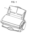
- FIG. 1 and FIG. 2 are structural diagrams of a scanner, showing the schematic structure of a scanner to which a sheet feeding apparatus according to the present invention is applied. Particularly, FIG. 1 shows an external view of the scanner, and FIG. 2 shows a schematic section of a scanner.
- the sheet feeding apparatus comprises a paper sheet mounting table (shooter) 31, a pick roller 32, a pick arm 33, a separating pad 34, feed rollers 35 and 36, and discharge rollers 37 and 38. And, the sheet feeding apparatus further comprises the sending element of the ultrasonic sensor 17 and the receiving element of the ultrasonic sensor 18 of an ultrasonic detector 1 to be described afterwards.
- the two-dot chain line represents the transfer path of paper sheets 100 and the arrow R represents the reading position of the paper sheets 100.
- the paper sheets 100 mounted on the paper sheet mounting table (shooter) 31 are picked by the pick roller 32 in a state of being subjected to an appropriate pressing force by the pick arm 33. Then, the paper sheets 100 are separated one by one sequentially from the bottom by the pick roller 32 and the separating pad 34. The picked paper sheets 100 are further transferred by the pick roller 32 to the feed rollers 35 and 36, transferred by the feed rollers 35 and 36 to their reading position, and discharged by the discharge rollers 37 and 38.
- the scanner shown in FIG. 1 and FIG. 2 is one example of image processing apparatus to which the sheet feeding apparatus according to the present invention is applied.
- the present invention can be applied sheet feeding apparatus for not only scanners but also copying machines, facsimile machines and the like.
- FIG. 3 and FIG. 4 show one example of structure of ultrasonic detector which is provided in the sheet feeding apparatus according to the present invention.
- the ultrasonic detector 1 detects the transfer of a plurality of paper sheets 100 by using ultrasonic waves.
- the ultrasonic detector 1 of the sheet feeding apparatus comprises the sending element of the ultrasonic sensor 17, its drive circuit (sending circuit; the same applies hereinafter) 41, the receiving element of the ultrasonic sensor 18, a setting unit (26) for setting the threshold for the transfer of a plurality of paper sheets 100 (double feed), and a detection unit (26) for detecting the transfer of a plurality of paper sheets 100.
- the sending element of the ultrasonic sensor 17 outputs ultrasonic waves.
- the drive circuit 41 supplies the sending element of the ultrasonic sensor 17 with a drive signal to drive the sensor 17.
- the drive circuit 41 comprises a circuit (capable of ON/OFF control) oscillating at a frequency near the resonance frequency of the sending element of the ultrasonic sensor 17.
- the receiving element of the ultrasonic sensor 18 is disposed opposite the sending element of the ultrasonic sensor 17 across the sheet transfer path in the sheet feeding apparatus, and receives the ultrasonic waves.
- the setting unit uses the output of the receiving element of the ultrasonic sensor 18 at the time of the stopping of the output of the sending element of the ultrasonic sensor 17 by the drive circuit 41 as a basic value, and sets a threshold for the detection of the transfer of a plurality of paper sheets 100.
- the detection unit compares the output of the receiving element of the ultrasonic sensor 18 with the threshold, and detects the transfer of a plurality of paper sheets 100.
- the ultrasonic detector 1 further comprises an (first-stage) amplifying circuit 21, a BPF (band pass filter) 22, an (second-stage) amplifying circuit 23, a sample hold (S&H) circuit 24, an AD converter 25, a CPU 26, a motor driver 27, a motor 28, a ROM 29 and RAM 30.
- a receiving circuit 14 shown in FIG. 4 That is, the receiving element of the ultrasonic sensor 18 outputs an electric signal corresponding to the ultrasonic wave received from the sending element of the ultrasonic sensor 17. And, the electric signal is amplified by the amplifying circuit 21, and is cleared of noise by the BPF 22 after the amplification. And, the signal cleared of noise is further amplified by the amplifying circuit 23.
- the AD converter 25 converts that value (analog signal) into a digital value (digital signal).
- This digital signal (input signal) is inputted to (the setting unit and detection unit of) the CPU 26 and analyzed.
- the setting unit and the detection unit which are realized by setting and detection processing programs set on the CPU 26 (and hardware) analyze the input signal.
- the setting and detection processing programs are stored into, for example, the ROM 29 and/or the RAM 30.
- the CPU 26 namely the detection unit
- in double feed detection for example, sends a drive signal to the motor driver 27 to have the motor 28 driven and to have the transfer of (a plurality of) paper sheets 100 stopped.
- the ultrasonic detector 1 comprises a sending circuit (drive circuit) 41.
- the sending circuit 41 comprises a drive IC 13, a resistance frequency adjusting oscillator (OSC) 15 and a variable resistor 16 shown in FIG. 4.
- OSC resistance frequency adjusting oscillator
- the drive IC 13 shown in FIG. 4 is a drive circuit which supplies the sending element of the ultrasonic sensor 17 with a drive signal to drive it. This causes the sending element of the ultrasonic sensor 17 to output an ultrasonic wave.
- the receiving element of the ultrasonic sensor 18 receives this ultrasonic wave, and outputs a detection signal according to the intensity of the received ultrasonic wave. For example, when no paper sheet 100 is present between the sending element of the ultrasonic sensor 17 and the receiving element of the ultrasonic sensor 18, the receiving element of the ultrasonic sensor 18 detects a signal of a certain level (referred to usual level).
- the receiving element of the ultrasonic sensor 18 detects a signal of a level below the usual level but higher than a prescribed threshold (referred to normal level).
- a prescribed threshold referred to normal level
- the receiving element of the ultrasonic sensor 18 detects a signal of a level below the usual level and the above-mentioned threshold (referred to abnormal level).
- the drive IC 13 is so controlled that the receiving element of the ultrasonic sensor 18 can receive a signal of the usual level (actually a signal equal to or higher than the usual level). That is, based on the ultrasonic wave received by the receiving element of the ultrasonic sensor 18, the drive IC 13 is so controlled as to match the drive frequency of the drive signal with the resonance frequency of the sending element of the ultrasonic sensor 17, as will be described afterwards (without using a variable resistor).
- FIG. 5A shows one example of setting unit and FIG. 6 shows a flow of processing for setting at the time of setting the threshold.
- the setting unit sets (generates) the threshold (decision slice value or Vslice) for the detection of transfer of a plurality of paper sheets 100 by using the output of the receiving element of the ultrasonic sensor 18 when the output of the sending element of the ultrasonic sensor 17 is stopped by the drive circuit 41, as the basic value.
- the threshold is determined by adding a fixed value to the output of the receiving element of the ultrasonic sensor at the time the output of the sending element of the ultrasonic sensor is stopped.
- sensor control unit 101 sends a control signal to the sending circuit 41 to stop the oscillation of the sending circuit 41. Also, the sensor control unit 101 applies a prescribed bias voltage to (an operational amplifier 106; see FIG. 12A of) the amplifying circuit 23.
- a Vslice generating unit 102 of the CPU 26 repeatedly receives from the AD converter 25 input signals iputted from the receiving element of the ultrasonic sensor 18 tens of times, for example, 32 times, computes their average, and uses it as a basic value Vbase (step S11). That is, it is equal to measure signals at 32 points in one raster, for example.
- the correction value ⁇ is empirically determined for each device to be installed, with the influence of noise and other factors being taken into consideration.
- correction value ⁇ may be determined in advance, or correction value ⁇ may be determined as a variable value for each apparatus on an ad hoc basis with the sensitivity of the ultrasonic sensor, fluctuations in its sound pressure or fitting, ambience, adhesion of paper powder and other factors being taken into consideration.
- FIG. 7 is a diagram showing paper sheets and the output transition of the receiving element of the ultrasonic sensor (US sensor), illustrating one example of threshold set by the processing so far described.
- the vertical axis represents the output (digital value) of the receiving element of the ultrasonic (US) sensor
- the horizontal axis represents the vertical scanning direction of paper sheets (raster).
- the corrected threshold Vslice is set to a level relative to the basic value Vbase as shown in FIG. 7, and used for detection of double feed. For example, when the transferred paper sheets are two sheets of 45K in ream weight (hereinafter referred to as 45K sheets), the input signal level (Vin) is below the threshold Vslice, and therefore it is judged that double feed has occurred (abnormal feed). When only one of this 45K sheet is transferred, though not shown, the input signal level (Vin) is even higher than in a case of one 135K sheet or one 195K sheet which is heavier in ream weight (or thicker), and surpass the threshold Vslice. Therefore, the state is judged as normal feed.
- FIG. 5B shows an example of detection unit.
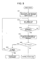
- FIG. 8 shows a flow of processing for detection after the setting of the threshold.
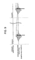
- FIG. 9 shows a drive pulse outputted by the sending circuit 41 in detecting double feed.
- the detection unit compares the output of the receiving element of the ultrasonic sensor 18 with the threshold, and detects transfer of a plurality of paper sheets 100. That is, as shown in FIG. 5B, the sensor control unit 101 in the CPU 26 sends a control signal to the sending circuit 41 etc. to oscillate the sending circuit 41. Also, the sensor control unit 101 applies prescribed bias voltage to (the operational amplifier 106 of) the amplifying circuit 23. In this state, comparing unit 104 of the CPU 26 repeatedly receives from the AD converter 25 input signals (digital values) from the receiving element of the ultrasonic sensor 18 tens of times, for example, 32 times, and holds them (step S21).
- the sending circuit 41 the sending drive pulse
- signals in a plurality of prescribed positions are measured.
- the measuring positions are selected to be, for example, once per the raster or once per a plurality of the rasters. Further, when the output waveform of the receiving element of the ultrasonic sensor 18 becomes gradually larger and reaches the maximum level, that maximum level is sampled and held.
- the sensor control unit 101 or the comparing unit 104 sets the timer for an SH interrupt (step S22), and judges whether or not the interrupt has occurred (step S23).
- 32 input signals are to be obtained, for example, as mentioned above, 32 times of the SH interrupt are set to occur. That is, using the SH interrupt as a trigger, consecutive drive pulses on the sending side shown in FIG. 9 are outputted.
- 32 times of the SH interrupt occur with the lapse of a prescribed length of time, at a rate of one interrupt per the raster.
- step S23 is repeated.
- the average for example, a moving average, of the 32 values earlier received and held is computed, and this average is used as the value Vin of the input signal for double feed (DF) detection (step S24).
- the comparing unit 104 compares the value Vin of the input signal with the threshold Vslice of the register 103 (step S25), and when Vin ⁇ Vslice is not satisfied, the state is judged as being normal feed. When Vin ⁇ Vslice is satisfied, the comparing unit 104 further judges whether Vin ⁇ Vslice is satisfied a prescribed number of times, for example, 10 times or more (step S26). When Vin ⁇ Vslice is satisfied 10 times or more, the comparing unit104 judges that double feed occurs and outputs an error signal. When Vin ⁇ Vslice is satisfied less than 10 times, the process of the step S22 and its subsequence is repeated.
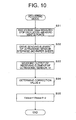
- FIG. 10 and FIG. 11 illustrate an ultrasonic detector 1 in a sheet feeding apparatus, which is another example of the present invention in which the correction value ⁇ is a variable value. That is, although a fixed value is used as the correction value ⁇ in the foregoing example as indicated at the step S12 in FIG. 6, this correction value ⁇ may be a variable value.
- the threshold Vslice in the detection of transfer of a plurality of paper sheets is calculated by adding a value ⁇ to an output Vbase.
- the output Vbase is an output of the receiving element of the ultrasonic sensor at the time the output of the sending element of the ultrasonic sensor 17 is stopped.
- the value ⁇ is calculated, correspondingly to the output Vt of the receiving element of the ultrasonic sensor 18 at the time the sending element of the ultrasonic sensor 17 is driven stepwise by the drive circuit 41, according to a (third) correlation between the output of the receiving element of the ultrasonic sensor 18 and the correction value ⁇ (shown in FIG. 11C).
- the third correlation is determined by a (first) correlation between the sensitivity and the output Vt of the receiving element of the ultrasonic sensor 18 (shown in FIG. 11A) and a (second) correlation between the fitting position and the output Vt of the receiving element of the ultrasonic sensor 18 (shown in FIG. 11B).
- step S31 a bias voltage is applied to measure the basic value Vbase (step S31).
- step S32 the sending element of the ultrasonic sensor 17 is driven stepwise (step S32). That is, the drive circuit 41 applies a single drive pulse to the sending element of the ultrasonic sensor 17.
- the correction value ⁇ is determined by using the correlation diagrams shown in FIG. 11A to FIG.11C as described above. That is, the sensor sensitivity and the sensor output Vt is in a proportional relationship as shown in FIG. 11A. The sensor fitting position and the sensor output Vt have the correlation shown in FIG. 11B. From the two correlations shown in FIG. 11A and FIG. 11B, the third correlation is derived between the sensor output Vt and the correction value ⁇ shown in FIG. 11C.
- FIG. 12A, FIG. 13 and FIG. 14 show a structure of the ultrasonic detector 1 in the other sheet feeding apparatus, which is the other example of the present invention, in which the output of the amplifying circuit 23 is adjusted not by varying an amplification rate with variable resistance, but by using some other units.
- the example shown in FIG. 12A and FIG. 13 comprises the amplifying circuit 23, which is an amplifier for amplifying the output of the receiving element of the ultrasonic sensor 18 and comprises the operational amplifier 106, and first adjusting unit which forms a control signal for adjusting the output of the amplifying circuit 23.
- the first adjusting unit adjusts the reference voltage Vref of the operational amplifier 106, so that the level of output from the amplifying circuit 23 is adjusted. More specifically, the offset of the operational amplifier 106 is adjusted (optimized for the receiving circuit 14).
- This first adjusting unit actually comprises the sensor control unit 101 and a voltage adjuster 107.
- the amplifying circuit 23 is the second-stage amplifier in FIG. 3.
- the amplifying circuit 23 comprises a fixed resistor 105, the operational amplifier 106 and the voltage adjuster 107 which may be a DA converter, for example.
- Numeral 108 denotes a fixed resistor. This example makes it possible to absorb fluctuations in resistance and temperature characteristics of the fixed resistors 105 and 108, to omit a manual adjustment at the time of shipment or sensor replacement, and to adapt themselves to status variations with the environment of use.
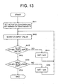
- FIG. 13 shows a process of adjusting the double feed output level.
- the sensor control unit 101 sets the central value of conversion by the DA converter, which is the voltage adjuster 107, to its intrinsic value (for example, x80 of 256 gradations), and sets the number of burst waves to be applied to the sending element of the ultrasonic sensor 17 to "0" (step S41). That is, the output of the sending element of the ultrasonic sensor 17 is set to "0".
- the sensor control unit 101 monitors (takes in) the input value Vin from the receiving element of the ultrasonic sensor 18 (step S42), and judges, after the monitoring, whether or not "the first slice upper limit" > "the input value” is satisfied (step S43).
- This first slice upper limit is an empirically determined value.
- the sensor control unit 101 sets the central value of conversion by the DA converter, which is the voltage adjuster 107, to a value shifted by +x01 (step S44), and the process of the step S42 and its subsequence is repeated.
- the sensor control unit 101 further judges whether or not "the input value” > “the first slice lower limit” is satisfied (step S45).
- This first slice lower limit is an empirically determined value.
- the sensor control unit 101 sets the central value of conversion by the DA converter, which is the voltage adjuster 107, to a value shifted by - x01 (step S46), and the process of the step S42 and its subsequence is repeated.
- the process is ended.
- the example shown in FIG. 12A and FIG. 14 comprises second adjusting unit.
- the second adjusting unit forms a control signal for adjusting the output of the amplifying circuit 23 which amplifies the output of the receiving element of the ultrasonic sensor 18.
- the number of waves (the number of pulses) or the duty ratio of the drive pulses (burst waves) is varied which is supplied by the drive circuit 41 according to a control signal from the second adjusting unit to the sending element of the ultrasonic sensor 17.
- the input value from the amplifying circuit 23 is thereby adjusted.
- This second adjusting unit actually comprises the sensor control unit 101 and the sending circuit (drive circuit) 41.
- This example makes it possible to absorb fluctuations in the sensitivity of the receiving element of the ultrasonic sensor 18, and to prevent from attenuating the sensor output even in a case that the receiving circuit 14 includes a band pass filter.
- FIG. 14 shows a process of adjusting the output level.
- the sensor control unit 101 sets the number of pulses (the number of waves) of drive pulses (burst waves) to be applied to the sending element of the ultrasonic sensor 17 to "1 wave" (step S51).
- the duty ratio then is set to 50%.
- the sensor control unit 101 monitors the input value Vin from the receiving element of the ultrasonic sensor 18 (step S52), and judges, after the monitoring, whether or not "the input value” > “the second slice upper limit” is satisfied (step S53).
- This second slice lower limit is an empirically determined value, and differs from the first slice lower limit.
- the sensor control unit 101 sets the number of burst waves to +1 (step S54), and then the process of the step S52 and its subsequence is repeated.
- the sensor control unit 101 monitors the input value Vin from the receiving element of the ultrasonic sensor 18 (step S55), and further judges, after the monitoring, whether or not "the second slice upper limit” > “the input value” is satisfied (step S56).
- This second slice upper limit is an empirically determined value, and differs from the first slice upper limit.
- the sensor control unit 101 sets the value of the duty ratio (%) to a value shifted by -1% (step S57), and the process of the step S55 and its subsequence is repeated.
- the process is ended.
- FIG. 12B one example of adjustment of the input value from a receiving element of the ultrasonic sensor 18 is shown in FIG. 12B.
- numeral 42 denotes an amplifier circuit
- 108 denotes a fixed resistor
- 109 denotes a variable resistance
- 110 denotes an operational amplifier
- Vref denotes a reference voltage.
- the input value from the receiving element of the ultrasonic sensor 18 is adjusted by varying the gain of the operational amplifier 110 with the variable resistance 109. This method, however, requires manual adjustment at the time of shipment or sensor replacement, and cannot adapt to status variations with the environment of use.
- the threshold (decision slice value) set in a sheet feeding apparatus since it is not fixed, can follow variations in the environment of detection or in the ultrasonic sensor's own characteristics and, even after shipment, double feed in the sheet feeding apparatus can be always detected accurately. That is, even in a case that the sensor output varies with fluctuations in the sensitivity, sound pressure or fitting of the ultrasonic sensor, its ambience or adhesion of paper powder, double feed can be detected without fail.
- the input value from the receiving element of the ultrasonic sensor in the sheet feeding apparatus is adjusted either by altering the reference voltage of the operational amplifier or altering the frequency of clocks supplied by the drive circuit or the duty ratio. Therefore, at the time of shipping the sheet feeding apparatus, for example, there is no need to adjust the amplification rate of the amplifier of the ultrasonic receiving circuit with a variable resistance. This is also true at the time of replacing the ultrasonic sensor, for example. Even in a case that the ultrasonic receiving circuit comprises a band pass filter, the output of the receiving element of the ultrasonic sensor can be prevented from attenuating.
Landscapes
- Controlling Sheets Or Webs (AREA)
- Handling Of Sheets (AREA)
- Paper Feeding For Electrophotography (AREA)
Abstract
A sheet feeding apparatus includes a sending element of an ultrasonic sensor (17) for outputting ultrasonic waves, a drive circuit (41) for supplying the sending element of the ultrasonic sensor (17) with a drive signal for driving the sending element, a receiving element of the ultrasonic sensor (18) disposed opposite the sending element of the ultrasonic sensor (17) across a sheet transfer path in the sheet feeding apparatus, and for receiving the ultrasonic waves, a setting unit (26) for setting a threshold for the detection of transfer of the plurality of paper sheets (100) by using the output of the receiving element of the ultrasonic sensor (18) at the time of stopping of the output of the sending element of the ultrasonic sensor (17) as a basic value, and a detection unit (26) for detecting transfer of the plurality of paper sheets (100) by comparing the output of the receiving element of the ultrasonic sensor (18) with the threshold.
Description
- This invention generally relates to a sheet feeding apparatus, and particularly to a sheet feeding apparatus which sets a threshold that enables, in double feed detection using ultrasonic waves, the double feed to be detected without fail even in a case that the sensor output is varied by fluctuations in the sensitivity or sound pressure of the ultrasonic sensor and the like.
- For use in the front shield device of a sheet-fed press, for example, an ultrasonic detector is known, which detects the transfer or feeding of a plurality of (for example, two) paper sheets (double feed or DF) by using ultrasonic waves. In this ultrasonic detector, ultrasonic waves outputted from a sending element of an ultrasonic sensor are received by a receiving element of the ultrasonic sensor, and it is detected whether there is one fed paper sheet or more according to the level (wave height) of the received ultrasonic waves. That is, when the level of the received ultrasonic waves is higher than a threshold, it is judged that there is only one sheet. On the other hand, when the level is lower than the threshold, it is judged that double feed has occurred (see, for example, Patent Document Reference 1: Japanese Patent Application Laid-Open No. 6-263288 (pp. 2-3)).
- However, according to the above-mentioned prior art, adjustment of every individual feeding apparatus is needed because, when each feeding apparatus is shipped, the amplification rate is adjusted with a variable resistance according to the characteristics of its ultrasonic sensor in a state in which a paper sheet is inserted in the device or a threshold for determining double feed detection (hereinafter sometimes referred to as a decision slice value) is determined and applied to the feeding apparatus according to prior evaluation. Moreover, readjustment is needed when ultrasonic sensor has run into trouble and is to be replaced.
- Further, in a case that the control is such as to determine the decision slice value uniquely, it is difficult to secure a sufficient margin of operation against variations in the ultrasonic sensor output due to fluctuations in the sensitivity of the ultrasonic sensor or its fitting to the feeding apparatus, ambience or adherence of paper powder. Therefore, it may be impossible to detect double feed when paper sheets of different thickness are consecutively carried.
- It is an object of the present invention to provide a sheet feeding apparatus in which a threshold permitting secure detection of double feed even when there are variations in the ultrasonic sensor output due to fluctuations in the sensitivity or sound pressure of the ultrasonic sensor.
- A sheet feeding apparatus of the present invention is for detecting transfer of a plurality of paper sheets by using ultrasonic waves. The sheet feeding apparatus includes a sending element of an ultrasonic sensor for outputting ultrasonic waves, a drive circuit for supplying the sending element of the ultrasonic sensor with a drive signal for driving the sending element, a receiving element of the ultrasonic sensor disposed opposite the sending element of the ultrasonic sensor across a sheet transfer path in the sheet feeding apparatus, and for receiving the ultrasonic waves, a setting unit for setting a threshold for the detection of transfer of the plurality of paper sheets by using the output of the receiving element of the ultrasonic sensor at the time of stopping of the output of the sending element of the ultrasonic sensor as a basic value, and a detection unit for detecting transfer of the plurality of paper sheets by comparing the output of the receiving element of the ultrasonic sensor with the threshold.
- According to the sheet feeding apparatus of the present invention, since the threshold for detecting transfer of a plurality of paper sheets is set by referencing the output of the receiving element of the ultrasonic sensor at the time of stopping of the output of the sending element of the ultrasonic sensor, the threshold (decision slice value) so set is not fixed. Therefore, it can follow variations in the environment of detection (for example, variations in the sheet feeding apparatus) or in the ultrasonic sensor's own characteristics (for example, aging) and, even after shipment, double feed in the sheet feeding apparatus can be always detected accurately. That is, even in a case that the sensor output varies with fluctuations in the sensitivity, sound pressure or fitting (accuracy) of the ultrasonic sensor, its ambience or adhesion of paper powder, double feed can be detected without fail.
- A sheet feeding apparatus of the present invention is for detecting transfer of a plurality of paper sheets by using ultrasonic waves. The sheet feeding apparatus includes a sending element of an ultrasonic sensor for outputting ultrasonic waves, a drive circuit for supplying the sending element of the ultrasonic sensor with a drive signal for driving the sending element, a receiving element of the ultrasonic sensor disposed opposite the sending element of the ultrasonic sensor across a sheet transfer path in the sheet feeding apparatus, and for receiving the ultrasonic waves, an amplifier, comprising an operational amplifier, for amplifying the output of the receiving element of the ultrasonic sensor, and an adjusting unit for forming a control signal for adjusting the output of the amplifier, whereby the reference voltage of the operational amplifier is adjusted.
- Further, a sheet feeding apparatus of the present invention is for detecting transfer of a plurality of paper sheets by using ultrasonic waves. The sheet feeding apparatus includes a sending element of an ultrasonic sensor for outputting ultrasonic waves, a receiving element of the ultrasonic sensor disposed opposite the sending element of the ultrasonic sensor across a sheet transfer path in the sheet feeding apparatus, and for receiving the ultrasonic waves, an amplifier for amplifying the output of the receiving element of the ultrasonic sensor, an adjusting unit for forming a control signal for adjusting the output of the amplifier, and a drive circuit for supplying the sending element of the ultrasonic sensor with a drive signal for driving the sending element. The drive circuit varies the number of waves or the duty ratio of clocks supplied to the sending element of the ultrasonic sensor according to the control signal from the adjusting unit.
- According to the sheet feeding apparatus of the present invention, the output value of the receiving element of the ultrasonic sensor is adjusted either by altering the reference voltage of the operational amplifier or altering the frequency of clocks supplied by the drive circuit or the duty ratio. Therefore, at the time of shipping the sheet feeding apparatus, for example, there is no need to adjust the amplification rate of the amplifier of the ultrasonic receiving circuit with a variable resistance. This is also true at the time of replacing the ultrasonic sensor, for example. Even in a case that the ultrasonic receiving circuit comprises a band pass filter, the output of the receiving element of the ultrasonic sensor can be prevented from attenuating.
-
- FIG. 1 is a structural diagram of a scanner, showing the schematic structure of a scanner to which a sheet feeding apparatus according to the present invention is applied.
- FIG. 2 is a structural diagram of a scanner, showing the schematic structure of a scanner to which a sheet feeding apparatus according to the present invention is applied.
- FIG. 3 is a diagram showing one example of structure of an ultrasonic detector.
- FIG. 4 is a diagram showing one example of structure of an ultrasonic detector.
- FIG. 5A and FIG. 5B are diagrams showing examples of operation by a CPU.
- FIG. 6 is a diagram showing one example of operation processing flow at the time of adjustment to determine Vslice.
- FIG. 7 is a diagram showing paper sheets and the output transition of a receiving element of the ultrasonic sensor (US sensor).
- FIG. 8 is a diagram showing one example of operation processing flow at the time of reading.
- FIG. 9 is a diagram showing a sensor reception waveform detected by the CPU.
- FIG. 10 is a diagram showing one example of processing flow to compute the correction value α.
- FIG. 11A, FIG. 11B and FIG. 11C are diagrams showing tables to be used for determining the correction value α.
- FIG. 12A and FIG. 12B are diagrams showing examples of device configuration for adjusting the input value of an ultrasonic wave reception sensor.
- FIG. 13 is a diagram showing a sequence of adjusting the double feed output level.
- FIG. 14 is a diagram showing a sequence of adjusting the double feed output level.
- FIG. 1 and FIG. 2 are structural diagrams of a scanner, showing the schematic structure of a scanner to which a sheet feeding apparatus according to the present invention is applied. Particularly, FIG. 1 shows an external view of the scanner, and FIG. 2 shows a schematic section of a scanner.
- This scanner is formed integrally with the sheet feeding apparatus. The sheet feeding apparatus, as shown in FIG. 2, comprises a paper sheet mounting table (shooter) 31, a
pick roller 32, apick arm 33, a separating pad 34,feed rollers discharge rollers ultrasonic sensor 17 and the receiving element of theultrasonic sensor 18 of anultrasonic detector 1 to be described afterwards. In FIG. 2, the two-dot chain line represents the transfer path ofpaper sheets 100 and the arrow R represents the reading position of thepaper sheets 100. - The
paper sheets 100 mounted on the paper sheet mounting table (shooter) 31 are picked by thepick roller 32 in a state of being subjected to an appropriate pressing force by thepick arm 33. Then, thepaper sheets 100 are separated one by one sequentially from the bottom by thepick roller 32 and the separating pad 34. The pickedpaper sheets 100 are further transferred by thepick roller 32 to thefeed rollers feed rollers discharge rollers - In the transferring process of these
paper sheets 100 along the transfer path, a plurality of (usually two)paper sheets 100 which have failed to be separated one by one by the separating pad 34, namely double fed ones are detected by the sending element of theultrasonic sensor 17 and the receiving element of theultrasonic sensor 18. For this reason, the sending element of theultrasonic sensor 17 and the receiving element of theultrasonic sensor 18 are located upstream on the transfer path from the reading position as shown in FIG. 2. Particularly, the sending element of theultrasonic sensor 17 and the receiving element of theultrasonic sensor 18 are positioned downstream or upstream from thefeed rollers rollers paper sheets 100 to be detected before they reach the reading position, and to proceed necessary process (for example, stopping of transfer). - Additionally, the scanner shown in FIG. 1 and FIG. 2 is one example of image processing apparatus to which the sheet feeding apparatus according to the present invention is applied. The present invention can be applied sheet feeding apparatus for not only scanners but also copying machines, facsimile machines and the like.
- FIG. 3 and FIG. 4 show one example of structure of ultrasonic detector which is provided in the sheet feeding apparatus according to the present invention. In FIG. 3, the
ultrasonic detector 1 detects the transfer of a plurality ofpaper sheets 100 by using ultrasonic waves. Theultrasonic detector 1 of the sheet feeding apparatus comprises the sending element of theultrasonic sensor 17, its drive circuit (sending circuit; the same applies hereinafter) 41, the receiving element of theultrasonic sensor 18, a setting unit (26) for setting the threshold for the transfer of a plurality of paper sheets 100 (double feed), and a detection unit (26) for detecting the transfer of a plurality ofpaper sheets 100. - The sending element of the
ultrasonic sensor 17 outputs ultrasonic waves. Thedrive circuit 41 supplies the sending element of theultrasonic sensor 17 with a drive signal to drive thesensor 17. Thedrive circuit 41 comprises a circuit (capable of ON/OFF control) oscillating at a frequency near the resonance frequency of the sending element of theultrasonic sensor 17. The receiving element of theultrasonic sensor 18 is disposed opposite the sending element of theultrasonic sensor 17 across the sheet transfer path in the sheet feeding apparatus, and receives the ultrasonic waves. The setting unit uses the output of the receiving element of theultrasonic sensor 18 at the time of the stopping of the output of the sending element of theultrasonic sensor 17 by thedrive circuit 41 as a basic value, and sets a threshold for the detection of the transfer of a plurality ofpaper sheets 100. The detection unit compares the output of the receiving element of theultrasonic sensor 18 with the threshold, and detects the transfer of a plurality ofpaper sheets 100. - The
ultrasonic detector 1 further comprises an (first-stage) amplifyingcircuit 21, a BPF (band pass filter) 22, an (second-stage) amplifyingcircuit 23, a sample hold (S&H)circuit 24, anAD converter 25, aCPU 26, amotor driver 27, amotor 28, aROM 29 andRAM 30. They make a receivingcircuit 14 shown in FIG. 4. That is, the receiving element of theultrasonic sensor 18 outputs an electric signal corresponding to the ultrasonic wave received from the sending element of theultrasonic sensor 17. And, the electric signal is amplified by the amplifyingcircuit 21, and is cleared of noise by theBPF 22 after the amplification. And, the signal cleared of noise is further amplified by the amplifyingcircuit 23. Then, after thesample hold circuit 24 samples and holds (SH) the peak value of the signal, theAD converter 25 converts that value (analog signal) into a digital value (digital signal). This digital signal (input signal) is inputted to (the setting unit and detection unit of) theCPU 26 and analyzed. In other words, the setting unit and the detection unit (see FIG. 5) which are realized by setting and detection processing programs set on the CPU 26 (and hardware) analyze the input signal. The setting and detection processing programs are stored into, for example, theROM 29 and/or theRAM 30. The CPU 26 (namely the detection unit), in double feed detection, for example, sends a drive signal to themotor driver 27 to have themotor 28 driven and to have the transfer of (a plurality of)paper sheets 100 stopped. - The
ultrasonic detector 1 comprises a sending circuit (drive circuit) 41. The sendingcircuit 41 comprises adrive IC 13, a resistance frequency adjusting oscillator (OSC) 15 and avariable resistor 16 shown in FIG. 4. - The
drive IC 13 shown in FIG. 4 is a drive circuit which supplies the sending element of theultrasonic sensor 17 with a drive signal to drive it. This causes the sending element of theultrasonic sensor 17 to output an ultrasonic wave. The receiving element of theultrasonic sensor 18 receives this ultrasonic wave, and outputs a detection signal according to the intensity of the received ultrasonic wave. For example, when nopaper sheet 100 is present between the sending element of theultrasonic sensor 17 and the receiving element of theultrasonic sensor 18, the receiving element of theultrasonic sensor 18 detects a signal of a certain level (referred to usual level). When onepaper sheet 100 is present between them, the receiving element of theultrasonic sensor 18 detects a signal of a level below the usual level but higher than a prescribed threshold (referred to normal level). When two (or more)paper sheets 100 are present between them, the receiving element of theultrasonic sensor 18 detects a signal of a level below the usual level and the above-mentioned threshold (referred to abnormal level). - For example, in advance of transferring
paper sheets 100, thedrive IC 13 is so controlled that the receiving element of theultrasonic sensor 18 can receive a signal of the usual level (actually a signal equal to or higher than the usual level). That is, based on the ultrasonic wave received by the receiving element of theultrasonic sensor 18, thedrive IC 13 is so controlled as to match the drive frequency of the drive signal with the resonance frequency of the sending element of theultrasonic sensor 17, as will be described afterwards (without using a variable resistor). - FIG. 5A shows one example of setting unit and FIG. 6 shows a flow of processing for setting at the time of setting the threshold.
- As described above, the setting unit sets (generates) the threshold (decision slice value or Vslice) for the detection of transfer of a plurality of
paper sheets 100 by using the output of the receiving element of theultrasonic sensor 18 when the output of the sending element of theultrasonic sensor 17 is stopped by thedrive circuit 41, as the basic value. In this example, the threshold is determined by adding a fixed value to the output of the receiving element of the ultrasonic sensor at the time the output of the sending element of the ultrasonic sensor is stopped. - That is, as shown in FIG. 5A, in the
CPU 26,sensor control unit 101 sends a control signal to the sendingcircuit 41 to stop the oscillation of the sendingcircuit 41. Also, thesensor control unit 101 applies a prescribed bias voltage to (anoperational amplifier 106; see FIG. 12A of) the amplifyingcircuit 23. In this state, aVslice generating unit 102 of theCPU 26 repeatedly receives from theAD converter 25 input signals iputted from the receiving element of theultrasonic sensor 18 tens of times, for example, 32 times, computes their average, and uses it as a basic value Vbase (step S11). That is, it is equal to measure signals at 32 points in one raster, for example. Then, theVslice generating unit 102 performs a correction to add a correction value α to the basic value Vbase to generate a threshold Vslice (Vslice = Vbase + α), and stores it into a register 103 (step S12). The correction value α is empirically determined for each device to be installed, with the influence of noise and other factors being taken into consideration. - The correction value α may be determined in advance, or correction value α may be determined as a variable value for each apparatus on an ad hoc basis with the sensitivity of the ultrasonic sensor, fluctuations in its sound pressure or fitting, ambience, adhesion of paper powder and other factors being taken into consideration.
- FIG. 7 is a diagram showing paper sheets and the output transition of the receiving element of the ultrasonic sensor (US sensor), illustrating one example of threshold set by the processing so far described. In FIG. 7, the vertical axis represents the output (digital value) of the receiving element of the ultrasonic (US) sensor, and the horizontal axis represents the vertical scanning direction of paper sheets (raster).
- The corrected threshold Vslice is set to a level relative to the basic value Vbase as shown in FIG. 7, and used for detection of double feed. For example, when the transferred paper sheets are two sheets of 45K in ream weight (hereinafter referred to as 45K sheets), the input signal level (Vin) is below the threshold Vslice, and therefore it is judged that double feed has occurred (abnormal feed). When only one of this 45K sheet is transferred, though not shown, the input signal level (Vin) is even higher than in a case of one 135K sheet or one 195K sheet which is heavier in ream weight (or thicker), and surpass the threshold Vslice. Therefore, the state is judged as normal feed. When two 135K or two 195K sheets are transferred, though not shown, the input signal level is even lower than in a case of one 45K sheet, and does not reach the threshold Vslice. Therefore, the state is judged as double feed. When only one 135K or one 195K sheet is transferred, the input signal level surpasses the threshold Vslice as shown in FIG. 7. Therefore, the state is judged as normal feed.
- Even in a case that the transferred sheets are 22K sheets, which are very light in ream weight and thin, double feed can be detected correctly. That is, when only one 22K sheet is transferred, though not shown, the input signal level (Vin) is even higher than in a case of one 135K sheet or the like, and surpasses the threshold Vslice. Therefore, the state is judged as normal feed. When two 22K sheets are transferred, the level of the input signal Vin fluctuates as shown in FIG. 7. However, on the right hand side of FIG. 7, the input signal Vin is lower and below the threshold Vslice. Therefore, the state can be judged as double feed. This is because the input signal becomes significantly low in the vicinity of the position where
paper sheets 100 are suppressed by thefeed rollers 35 through 38. That is, according to the present invention, double feed can be correctly detected over a broad range. - FIG. 5B shows an example of detection unit. FIG. 8 shows a flow of processing for detection after the setting of the threshold. FIG. 9 shows a drive pulse outputted by the sending
circuit 41 in detecting double feed. - As described above, the detection unit compares the output of the receiving element of the
ultrasonic sensor 18 with the threshold, and detects transfer of a plurality ofpaper sheets 100. That is, as shown in FIG. 5B, thesensor control unit 101 in theCPU 26 sends a control signal to the sendingcircuit 41 etc. to oscillate the sendingcircuit 41. Also, thesensor control unit 101 applies prescribed bias voltage to (theoperational amplifier 106 of) the amplifyingcircuit 23. In this state, comparingunit 104 of theCPU 26 repeatedly receives from theAD converter 25 input signals (digital values) from the receiving element of theultrasonic sensor 18 tens of times, for example, 32 times, and holds them (step S21). - Then, as shown in FIG. 9, after the oscillation of the sending circuit 41 (the sending drive pulse) is stopped, signals in a plurality of prescribed positions, for example, at 32 points, are measured. The measuring positions are selected to be, for example, once per the raster or once per a plurality of the rasters. Further, when the output waveform of the receiving element of the
ultrasonic sensor 18 becomes gradually larger and reaches the maximum level, that maximum level is sampled and held. - Next, the
sensor control unit 101 or the comparingunit 104 sets the timer for an SH interrupt (step S22), and judges whether or not the interrupt has occurred (step S23). In a case that 32 input signals are to be obtained, for example, as mentioned above, 32 times of the SH interrupt are set to occur. That is, using the SH interrupt as a trigger, consecutive drive pulses on the sending side shown in FIG. 9 are outputted. For example, 32 times of the SH interrupt occur with the lapse of a prescribed length of time, at a rate of one interrupt per the raster. When no interrupt occurs, step S23 is repeated. When an interrupt does occur, the average, for example, a moving average, of the 32 values earlier received and held is computed, and this average is used as the value Vin of the input signal for double feed (DF) detection (step S24). - After that, the comparing
unit 104 compares the value Vin of the input signal with the threshold Vslice of the register 103 (step S25), and when Vin < Vslice is not satisfied, the state is judged as being normal feed. When Vin < Vslice is satisfied, the comparingunit 104 further judges whether Vin < Vslice is satisfied a prescribed number of times, for example, 10 times or more (step S26). When Vin < Vslice is satisfied 10 times or more, the comparing unit104 judges that double feed occurs and outputs an error signal. When Vin < Vslice is satisfied less than 10 times, the process of the step S22 and its subsequence is repeated. - FIG. 10 and FIG. 11 illustrate an
ultrasonic detector 1 in a sheet feeding apparatus, which is another example of the present invention in which the correction value α is a variable value. That is, although a fixed value is used as the correction value α in the foregoing example as indicated at the step S12 in FIG. 6, this correction value α may be a variable value. - In this example, as shown in FIG. 11, the threshold Vslice in the detection of transfer of a plurality of paper sheets is calculated by adding a value α to an output Vbase. The output Vbase is an output of the receiving element of the ultrasonic sensor at the time the output of the sending element of the
ultrasonic sensor 17 is stopped. The value α is calculated, correspondingly to the output Vt of the receiving element of theultrasonic sensor 18 at the time the sending element of theultrasonic sensor 17 is driven stepwise by thedrive circuit 41, according to a (third) correlation between the output of the receiving element of theultrasonic sensor 18 and the correction value α (shown in FIG. 11C). The third correlation is determined by a (first) correlation between the sensitivity and the output Vt of the receiving element of the ultrasonic sensor 18 (shown in FIG. 11A) and a (second) correlation between the fitting position and the output Vt of the receiving element of the ultrasonic sensor 18 (shown in FIG. 11B). - In the same way as at the step S11, a bias voltage is applied to measure the basic value Vbase (step S31). Next, in a state without paper sheets, the sending element of the
ultrasonic sensor 17 is driven stepwise (step S32). That is, thedrive circuit 41 applies a single drive pulse to the sending element of theultrasonic sensor 17. And the resultant output Vt of the receiving element of theultrasonic sensor 18 is measured (step S33), a correction value α corresponding to the output Vt is calculated by using the third correlation shown in FIG. 11C (step S34), and the threshold Vslice = Vbase + α is determined by using the correction value α (step S35). - For example, the correction value α is determined by using the correlation diagrams shown in FIG. 11A to FIG.11C as described above. That is, the sensor sensitivity and the sensor output Vt is in a proportional relationship as shown in FIG. 11A. The sensor fitting position and the sensor output Vt have the correlation shown in FIG. 11B. From the two correlations shown in FIG. 11A and FIG. 11B, the third correlation is derived between the sensor output Vt and the correction value α shown in FIG. 11C.
- FIG. 12A, FIG. 13 and FIG. 14 show a structure of the
ultrasonic detector 1 in the other sheet feeding apparatus, which is the other example of the present invention, in which the output of the amplifyingcircuit 23 is adjusted not by varying an amplification rate with variable resistance, but by using some other units. - That is, the example shown in FIG. 12A and FIG. 13 comprises the amplifying
circuit 23, which is an amplifier for amplifying the output of the receiving element of theultrasonic sensor 18 and comprises theoperational amplifier 106, and first adjusting unit which forms a control signal for adjusting the output of the amplifyingcircuit 23. The first adjusting unit adjusts the reference voltage Vref of theoperational amplifier 106, so that the level of output from the amplifyingcircuit 23 is adjusted. More specifically, the offset of theoperational amplifier 106 is adjusted (optimized for the receiving circuit 14). This first adjusting unit actually comprises thesensor control unit 101 and avoltage adjuster 107. The amplifyingcircuit 23 is the second-stage amplifier in FIG. 3. The amplifyingcircuit 23 comprises a fixedresistor 105, theoperational amplifier 106 and thevoltage adjuster 107 which may be a DA converter, for example.Numeral 108 denotes a fixed resistor. This example makes it possible to absorb fluctuations in resistance and temperature characteristics of the fixedresistors - FIG. 13 shows a process of adjusting the double feed output level. The
sensor control unit 101 sets the central value of conversion by the DA converter, which is thevoltage adjuster 107, to its intrinsic value (for example, x80 of 256 gradations), and sets the number of burst waves to be applied to the sending element of theultrasonic sensor 17 to "0" (step S41). That is, the output of the sending element of theultrasonic sensor 17 is set to "0". In this state, thesensor control unit 101 monitors (takes in) the input value Vin from the receiving element of the ultrasonic sensor 18 (step S42), and judges, after the monitoring, whether or not "the first slice upper limit" > "the input value" is satisfied (step S43). This first slice upper limit is an empirically determined value. When "the first slice upper limit" > "the input value" is not satisfied, thesensor control unit 101 sets the central value of conversion by the DA converter, which is thevoltage adjuster 107, to a value shifted by +x01 (step S44), and the process of the step S42 and its subsequence is repeated. When "the first slice upper limit" > "the input value" is satisfied, thesensor control unit 101 further judges whether or not "the input value" > "the first slice lower limit" is satisfied (step S45). This first slice lower limit is an empirically determined value. When "the input value" > "the first slice lower limit" is not satisfied, thesensor control unit 101 sets the central value of conversion by the DA converter, which is thevoltage adjuster 107, to a value shifted by -x01 (step S46), and the process of the step S42 and its subsequence is repeated. When "the input value" > "the first slice lower limit" is satisfied, the process is ended. - Further, the example shown in FIG. 12A and FIG. 14 comprises second adjusting unit. The second adjusting unit forms a control signal for adjusting the output of the amplifying
circuit 23 which amplifies the output of the receiving element of theultrasonic sensor 18. And, the number of waves (the number of pulses) or the duty ratio of the drive pulses (burst waves) is varied which is supplied by thedrive circuit 41 according to a control signal from the second adjusting unit to the sending element of theultrasonic sensor 17. The input value from the amplifyingcircuit 23 is thereby adjusted. This second adjusting unit actually comprises thesensor control unit 101 and the sending circuit (drive circuit) 41. This example makes it possible to absorb fluctuations in the sensitivity of the receiving element of theultrasonic sensor 18, and to prevent from attenuating the sensor output even in a case that the receivingcircuit 14 includes a band pass filter. - FIG. 14 shows a process of adjusting the output level. The
sensor control unit 101 sets the number of pulses (the number of waves) of drive pulses (burst waves) to be applied to the sending element of theultrasonic sensor 17 to "1 wave" (step S51). The duty ratio then is set to 50%. In this state, thesensor control unit 101 monitors the input value Vin from the receiving element of the ultrasonic sensor 18 (step S52), and judges, after the monitoring, whether or not "the input value" > "the second slice upper limit" is satisfied (step S53). This second slice lower limit is an empirically determined value, and differs from the first slice lower limit. When "the input value" > "the second slice lower limit" is not satisfied, thesensor control unit 101 sets the number of burst waves to +1 (step S54), and then the process of the step S52 and its subsequence is repeated. When "the input value" > "the second slice lower limit" is satisfied, thesensor control unit 101 monitors the input value Vin from the receiving element of the ultrasonic sensor 18 (step S55), and further judges, after the monitoring, whether or not "the second slice upper limit" > "the input value" is satisfied (step S56). This second slice upper limit is an empirically determined value, and differs from the first slice upper limit. When "the second slice upper limit" > "the input value" is not satisfied, thesensor control unit 101 sets the value of the duty ratio (%) to a value shifted by -1% (step S57), and the process of the step S55 and its subsequence is repeated. When "the second slice upper limit" > "the input value" is satisfied, the process is ended. - Additionally, for comparison with FIG. 12A, one example of adjustment of the input value from a receiving element of the
ultrasonic sensor 18 is shown in FIG. 12B. In FIG. 12B, numeral 42 denotes an amplifier circuit, 108 denotes a fixed resistor, 109 denotes a variable resistance, 110 denotes an operational amplifier, and Vref denotes a reference voltage. As shown in FIG. 12B, according to the prior art, the input value from the receiving element of theultrasonic sensor 18 is adjusted by varying the gain of theoperational amplifier 110 with thevariable resistance 109. This method, however, requires manual adjustment at the time of shipment or sensor replacement, and cannot adapt to status variations with the environment of use. - As described above, according to the present invention, the threshold (decision slice value) set in a sheet feeding apparatus, since it is not fixed, can follow variations in the environment of detection or in the ultrasonic sensor's own characteristics and, even after shipment, double feed in the sheet feeding apparatus can be always detected accurately. That is, even in a case that the sensor output varies with fluctuations in the sensitivity, sound pressure or fitting of the ultrasonic sensor, its ambience or adhesion of paper powder, double feed can be detected without fail.
- Further, according to the present invention, the input value from the receiving element of the ultrasonic sensor in the sheet feeding apparatus is adjusted either by altering the reference voltage of the operational amplifier or altering the frequency of clocks supplied by the drive circuit or the duty ratio. Therefore, at the time of shipping the sheet feeding apparatus, for example, there is no need to adjust the amplification rate of the amplifier of the ultrasonic receiving circuit with a variable resistance. This is also true at the time of replacing the ultrasonic sensor, for example. Even in a case that the ultrasonic receiving circuit comprises a band pass filter, the output of the receiving element of the ultrasonic sensor can be prevented from attenuating.
Claims (12)
- A sheet feeding apparatus for detecting transfer of a plurality of paper sheets by using ultrasonic waves, the apparatus comprising:a sending element of an ultrasonic sensor for outputting ultrasonic waves;a drive circuit for supplying the sending element of the ultrasonic sensor with a drive signal for driving the sending element;a receiving element of the ultrasonic sensor disposed opposite the sending element of the ultrasonic sensor across a sheet transfer path in the sheet feeding apparatus, and for receiving the ultrasonic waves;a setting unit for setting a threshold for the detection of transfer of the plurality of paper sheets by using the output of the receiving element of the ultrasonic sensor at the time of stopping of the output of the sending element of the ultrasonic sensor as a basic value; anda detection unit for detecting transfer of the plurality of paper sheets by comparing the output of the receiving element of the ultrasonic sensor with the threshold.
- The sheet feeding apparatus according to claim 1, wherein the threshold for detecting transfer of the plurality of paper sheets is obtained by adding a fixed value to the output of the receiving element of the ultrasonic sensor at the time of stopping the output of the sending element of the ultrasonic sensor.
- The sheet feeding apparatus according to claim 1, wherein the threshold for detecting transfer of the plurality of paper sheets is obtained by adding, to the output of the receiving element of the ultrasonic sensor at the time of stopping of the output of the sending element of the ultrasonic sensor, a value calculated, correspondingly to the output of the receiving element of the ultrasonic sensor at the time the sending element of the ultrasonic sensor is driven stepwise by the drive circuit, according to the correlation between the output and a correction value determined based on the correlation between the sensitivity and the output of the receiving element of the ultrasonic sensor and the correlation between the fitting position and the output of the receiving element of the ultrasonic sensor.
- The sheet feeding apparatus according to claim 1, wherein the output of the receiving element of the ultrasonic sensor at the time of stopping of the output of the sending element of the ultrasonic sensor is the average of a plurality of the outputs.
- The sheet feeding apparatus according to claim 1, wherein the output of the receiving element of the ultrasonic sensor is the average of a plurality of the outputs.
- The sheet feeding apparatus according to claim 1, wherein the detection unit judges that, when the output of the receiving element of the ultrasonic sensor is lower than the threshold a prescribed number of times or more often, transfer of the plurality of paper sheets is taking place.
- The sheet feeding apparatus according to claim 1, wherein the detection unit uses the threshold as a threshold for detecting transfer of the plurality of paper sheets regarding a plurality of types of paper sheets differing in ream weight.
- The sheet feeding apparatus according to claim 1, further comprising:a motor for transferring paper sheets,wherein the detection unit, in the event of detecting transfer of the plurality of paper sheets, drives the motor to stop the transfer of the paper sheets.
- The sheet feeding apparatus according to claim 1, further comprising:feed rollers for transferring paper sheets to a reading position,wherein the sending element of the ultrasonic sensor and receiving element of the ultrasonic sensor are disposed upstream from the reading position on the transfer path and in the vicinity of downstream or upstream from the feed rollers.
- The sheet feeding apparatus according to claim 1, further comprising:a first amplifying circuit for amplifying the output of the receiving element of the ultrasonic sensor;a filter for removing noise from the output of the first amplifying circuit;a second amplifying circuit for amplifying the signals cleared of noise;a sample hold circuit for sampling and holding the peak value of the output of the second amplifying circuit; andan AD converter for converting the value held by the sample hold circuit into a digital signal and inputting it to the setting unit.
- A sheet feeding apparatus for detecting transfer of a plurality of paper sheets by using ultrasonic waves, the apparatus comprising:a sending element of an ultrasonic sensor for outputting ultrasonic waves;a drive circuit for supplying the sending element of the ultrasonic sensor with a drive signal for driving the sending element;a receiving element of the ultrasonic sensor disposed opposite the sending element of the ultrasonic sensor across a sheet transfer path in the sheet feeding apparatus, and for receiving the ultrasonic waves;an amplifier, comprising an operational amplifier, for amplifying the output of the receiving element of the ultrasonic sensor; andan adjusting unit for forming a control signal for adjusting the output of the amplifier, whereby the reference voltage of the operational amplifier is adjusted.
- A sheet feeding apparatus for detecting transfer of a plurality of paper sheets by using ultrasonic waves, the apparatus comprising:a sending element of an ultrasonic sensor for outputting ultrasonic waves;a receiving element of the ultrasonic sensor disposed opposite the sending element of the ultrasonic sensor across a sheet transfer path in the sheet feeding apparatus, and for receiving the ultrasonic waves;an amplifier for amplifying the output of the receiving element of the ultrasonic sensor;an adjusting unit for forming a control signal for adjusting the output of the amplifier; anda drive circuit for supplying the sending element of the ultrasonic sensor with a drive signal for driving the sending element, the drive circuit varying the number of waves or the duty ratio of clocks supplied to the sending element of the ultrasonic sensor according to the control signal from the adjusting unit.
Applications Claiming Priority (2)
| Application Number | Priority Date | Filing Date | Title |
|---|---|---|---|
| JP2003066277A JP2004269241A (en) | 2003-03-12 | 2003-03-12 | Paper feeder |
| PCT/JP2004/003132 WO2004080866A1 (en) | 2003-03-12 | 2004-03-10 | Paper feeder |
Publications (2)
| Publication Number | Publication Date |
|---|---|
| EP1612168A1 true EP1612168A1 (en) | 2006-01-04 |
| EP1612168A4 EP1612168A4 (en) | 2008-04-02 |
Family
ID=32984529
Family Applications (1)
| Application Number | Title | Priority Date | Filing Date |
|---|---|---|---|
| EP04719090A Withdrawn EP1612168A4 (en) | 2003-03-12 | 2004-03-10 | PAPER FEEDING DEVICE |
Country Status (4)
| Country | Link |
|---|---|
| US (1) | US20060145412A1 (en) |
| EP (1) | EP1612168A4 (en) |
| JP (1) | JP2004269241A (en) |
| WO (1) | WO2004080866A1 (en) |
Cited By (4)
| Publication number | Priority date | Publication date | Assignee | Title |
|---|---|---|---|---|
| US20100266763A1 (en) * | 2007-12-19 | 2010-10-21 | Evonik Degussa Gmbh | Method for Producing Encapsulated Sodium Percarbonate Particles |
| WO2013085950A3 (en) * | 2011-12-06 | 2013-08-01 | Eastman Kodak Company | Using audio to detect misfeed or multifeed |
| US8585050B2 (en) | 2011-12-06 | 2013-11-19 | Eastman Kodak Company | Combined ultrasonic-based multifeed detection system and sound-based damage detection system |
| WO2014197683A1 (en) * | 2013-06-06 | 2014-12-11 | Kodak Alaris Inc. | Self-adjusting audio detection of medium jam |
Families Citing this family (25)
| Publication number | Priority date | Publication date | Assignee | Title |
|---|---|---|---|---|
| JP4659546B2 (en) * | 2005-07-21 | 2011-03-30 | キヤノン電子株式会社 | Double feed detector |
| TWI329611B (en) * | 2007-04-02 | 2010-09-01 | Avision Inc | Sheet-conveying apparatus and method for detection of multiple documents thereof |
| JP2009073603A (en) * | 2007-09-19 | 2009-04-09 | Komori Corp | Sheet-like material duplication detection device and duplication detection method |
| JP5570232B2 (en) * | 2010-01-29 | 2014-08-13 | キヤノン電子株式会社 | Double feed detection device, double feed detection method, and sheet processing apparatus |
| JP5451519B2 (en) | 2010-05-14 | 2014-03-26 | 株式会社Pfu | Image reading apparatus, multifeed determination method, and multifeed determination program |
| JP5451520B2 (en) | 2010-05-14 | 2014-03-26 | 株式会社Pfu | Multifeed processing apparatus, multifeed processing method, and multifeed processing program |
| JP5525329B2 (en) | 2010-05-14 | 2014-06-18 | 株式会社Pfu | Multifeed processing apparatus, multifeed processing method, and multifeed processing program |
| JP5548518B2 (en) | 2010-05-14 | 2014-07-16 | 株式会社Pfu | Image display device, image display method, and image display program |
| JP5525328B2 (en) | 2010-05-14 | 2014-06-18 | 株式会社Pfu | Image reading apparatus, multifeed determination method, and multifeed determination program |
| JP2012232844A (en) | 2011-04-20 | 2012-11-29 | Seiko Epson Corp | Image processing device and sheet feeding mechanism |
| JP5669700B2 (en) * | 2011-09-20 | 2015-02-12 | 株式会社Pfu | Medium conveying apparatus and medium conveying method |
| JP5939829B2 (en) * | 2012-02-17 | 2016-06-22 | キヤノン株式会社 | Sheet feeding apparatus and image forming apparatus |
| DE202012004305U1 (en) * | 2012-04-27 | 2012-05-25 | Texmag Gmbh Vertriebsgesellschaft | Device for detecting an edge of a material web |
| JP2015037982A (en) | 2012-08-24 | 2015-02-26 | 株式会社Pfu | Document feeder, jam determination method, and computer program |
| JP5404872B1 (en) | 2012-08-24 | 2014-02-05 | 株式会社Pfu | Paper transport device, multifeed judgment method, and computer program |
| JP5404876B1 (en) | 2012-08-24 | 2014-02-05 | 株式会社Pfu | Paper transport device, jam determination method, and computer program |
| JP5404870B1 (en) | 2012-08-24 | 2014-02-05 | 株式会社Pfu | Paper reading device, jam determination method, and computer program |
| JP5404880B1 (en) * | 2012-09-14 | 2014-02-05 | 株式会社Pfu | Paper transport device, abnormality determination method, and computer program |
| US9542787B2 (en) | 2013-03-15 | 2017-01-10 | De La Rue North America Inc. | Systems and methods for detecting a document attribute using acoustics |
| JP6155895B2 (en) * | 2013-06-20 | 2017-07-05 | マックス株式会社 | Paper double feed detection method and paper double feed detection device |
| EP3118650A1 (en) * | 2015-07-17 | 2017-01-18 | Pepperl + Fuchs GmbH | Ultrasonic measuring device and method for determination the change in the amplitude of an ultrasonic signal |
| JP6622517B2 (en) * | 2015-08-27 | 2019-12-18 | キヤノン株式会社 | Sheet conveying apparatus and image reading apparatus |
| JP6849421B2 (en) * | 2016-12-14 | 2021-03-24 | キヤノン株式会社 | Control method of sheet feeding device, image forming device, and sheet feeding device |
| JP7098936B2 (en) * | 2018-01-15 | 2022-07-12 | セイコーエプソン株式会社 | Transport device |
| JP1640742S (en) * | 2019-02-27 | 2020-03-02 |
Family Cites Families (15)
| Publication number | Priority date | Publication date | Assignee | Title |
|---|---|---|---|---|
| JPS6045831B2 (en) * | 1978-10-11 | 1985-10-12 | 鈴木魚探株式会社 | Noise removal method |
| US4368438A (en) * | 1981-01-26 | 1983-01-11 | Oce-Nederland B.V. | System for detecting sheet-like objects |
| JPS6270707A (en) * | 1985-09-25 | 1987-04-01 | Sanko Seiki Kk | Stratification detector utilizing ultrasonic wave |
| JPH04260557A (en) * | 1991-02-15 | 1992-09-16 | Mitsubishi Heavy Ind Ltd | Method of setting signal receiving voltage serving as criteria for determination of detection for ultrasonic two sheet detector |
| JPH0556851U (en) * | 1991-04-13 | 1993-07-27 | 株式会社コスモテック | Double feed detector |
| JPH0540030A (en) * | 1991-04-13 | 1993-02-19 | Cosmo Tec:Kk | Device for detecting double-sending |
| JP2552768B2 (en) * | 1991-04-19 | 1996-11-13 | 株式会社ピーエフユー | Paper double feed detector |
| JPH08208073A (en) * | 1995-01-31 | 1996-08-13 | Fuji Photo Film Co Ltd | Superposed delivery detection method for sheet material and device therefor |
| JPH10329964A (en) * | 1997-05-31 | 1998-12-15 | Omron Corp | Paper feeder |
| JP3720534B2 (en) * | 1997-06-11 | 2005-11-30 | キヤノンファインテック株式会社 | Media detection method and apparatus |
| JP2000028358A (en) * | 1998-07-10 | 2000-01-28 | Tokimec Inc | Ultrasonic range finer |
| JP2000211769A (en) * | 1999-01-21 | 2000-08-02 | Omron Corp | Paper sheet detector |
| US6511064B1 (en) * | 2000-04-19 | 2003-01-28 | Eastman Kodak Company | Method and apparatus for multiple document detection using ultrasonic phase shift amplitude |
| JP2002087641A (en) * | 2000-09-08 | 2002-03-27 | Matsushita Electric Ind Co Ltd | Double feed detection method of sheet material using ultrasonic wave |
| JP2003160257A (en) * | 2001-11-22 | 2003-06-03 | Omron Corp | Paper sheet double feed detection device and method, and program |
-
2003
- 2003-03-12 JP JP2003066277A patent/JP2004269241A/en active Pending
-
2004
- 2004-03-10 WO PCT/JP2004/003132 patent/WO2004080866A1/en not_active Ceased
- 2004-03-10 US US10/546,781 patent/US20060145412A1/en not_active Abandoned
- 2004-03-10 EP EP04719090A patent/EP1612168A4/en not_active Withdrawn
Cited By (9)
| Publication number | Priority date | Publication date | Assignee | Title |
|---|---|---|---|---|
| US20100266763A1 (en) * | 2007-12-19 | 2010-10-21 | Evonik Degussa Gmbh | Method for Producing Encapsulated Sodium Percarbonate Particles |
| WO2013085950A3 (en) * | 2011-12-06 | 2013-08-01 | Eastman Kodak Company | Using audio to detect misfeed or multifeed |
| US8567777B2 (en) | 2011-12-06 | 2013-10-29 | Eastman Kodak Company | Combined ultrasonic-based multifeed detection method and sound-based damage detection method |
| US8585050B2 (en) | 2011-12-06 | 2013-11-19 | Eastman Kodak Company | Combined ultrasonic-based multifeed detection system and sound-based damage detection system |
| US9395277B2 (en) | 2011-12-06 | 2016-07-19 | Kodak Alaris Inc. | Self-adjusting audio detection of medium jam |
| WO2014197683A1 (en) * | 2013-06-06 | 2014-12-11 | Kodak Alaris Inc. | Self-adjusting audio detection of medium jam |
| CN105358460A (en) * | 2013-06-06 | 2016-02-24 | 柯达阿拉里斯股份有限公司 | Self-adjusting audio detection of medium jam |
| CN105358460B (en) * | 2013-06-06 | 2017-10-27 | 柯达阿拉里斯股份有限公司 | The voluntarily adjustment audio detection that medium is blocked |
| EP3753880A1 (en) * | 2013-06-06 | 2020-12-23 | Kodak Alaris Inc. | Self-adjusting audio detection of medium jam |
Also Published As
| Publication number | Publication date |
|---|---|
| JP2004269241A (en) | 2004-09-30 |
| EP1612168A4 (en) | 2008-04-02 |
| WO2004080866A1 (en) | 2004-09-23 |
| US20060145412A1 (en) | 2006-07-06 |
Similar Documents
| Publication | Publication Date | Title |
|---|---|---|
| US20060145412A1 (en) | Paper feeder | |
| EP2099704B1 (en) | Method of monitoring a sequence of documents | |
| US20040135106A1 (en) | Media type sensing method for an imaging apparatus | |
| US9981819B2 (en) | Sheet conveyance apparatus that detects overlapping of plurality of sheets, and image reading apparatus | |
| JP3860126B2 (en) | Double feed detection device and double feed detection method | |
| US8929758B2 (en) | Method and apparatus for compensation of banding from multiple sources in marking platform | |
| US8882225B2 (en) | Printing apparatus, driving apparatus, and driving method | |
| JP2019119578A (en) | Detection device, image formation device, detection method | |
| US6397671B1 (en) | Sheet detecting device | |
| JP2006298598A (en) | Multi-feed detection device and multi-feed detection method for sheet-like member | |
| JP5292561B2 (en) | Multi-feed detection device for sheet-like member | |
| JP6579939B2 (en) | Double feed detection device, double feed detection method and control program | |
| US6937263B2 (en) | Image forming apparatus and light amount correction method | |
| JP4136124B2 (en) | Method for detecting end position of recording paper using reflection type optical sensor and image forming apparatus | |
| US10730712B2 (en) | Conveyance apparatus, reading apparatus, image forming apparatus and image forming system | |
| US8882373B2 (en) | Image processing device and sheet feeding mechanism | |
| EP1156328A2 (en) | A method and apparatus for correcting for a phase shift between a transmitter and a receiver | |
| JP5570232B2 (en) | Double feed detection device, double feed detection method, and sheet processing apparatus | |
| JP2019123603A (en) | Sheet conveying device, control method and program for sheet conveying device | |
| JP2000025986A (en) | Method of detecting double feed of sheet material using ultrasonic waves | |
| US20220210279A1 (en) | Image reading apparatus and multi-sheet feed detection method | |
| JP3994669B2 (en) | Photodetector | |
| JP2001139189A (en) | Paper thickness detection device and printing device | |
| JP2019123580A (en) | Conveying device | |
| JP2018104119A (en) | Double-feed detection device, control method thereof, and image forming apparatus |
Legal Events
| Date | Code | Title | Description |
|---|---|---|---|
| PUAI | Public reference made under article 153(3) epc to a published international application that has entered the european phase |
Free format text: ORIGINAL CODE: 0009012 |
|
| 17P | Request for examination filed |
Effective date: 20050921 |
|
| AK | Designated contracting states |
Kind code of ref document: A1 Designated state(s): AT BE BG CH CY CZ DE DK EE ES FI FR GB GR HU IE IT LI LU MC NL PL PT RO SE SI SK TR |
|
| AX | Request for extension of the european patent |
Extension state: AL LT LV MK |
|
| DAX | Request for extension of the european patent (deleted) | ||
| RBV | Designated contracting states (corrected) |
Designated state(s): DE |
|
| A4 | Supplementary search report drawn up and despatched |
Effective date: 20080304 |
|
| STAA | Information on the status of an ep patent application or granted ep patent |
Free format text: STATUS: THE APPLICATION IS DEEMED TO BE WITHDRAWN |
|
| 18D | Application deemed to be withdrawn |
Effective date: 20091001 |