EP1612011A1 - Anvil for an rotary cutting unit and a rotary cutting unit having such anvil - Google Patents
Anvil for an rotary cutting unit and a rotary cutting unit having such anvil Download PDFInfo
- Publication number
- EP1612011A1 EP1612011A1 EP20050010601 EP05010601A EP1612011A1 EP 1612011 A1 EP1612011 A1 EP 1612011A1 EP 20050010601 EP20050010601 EP 20050010601 EP 05010601 A EP05010601 A EP 05010601A EP 1612011 A1 EP1612011 A1 EP 1612011A1
- Authority
- EP
- European Patent Office
- Prior art keywords
- anvil
- members
- load
- rotary cutting
- anvil portion
- Prior art date
- Legal status (The legal status is an assumption and is not a legal conclusion. Google has not performed a legal analysis and makes no representation as to the accuracy of the status listed.)
- Granted
Links
Images



Classifications
-
- B—PERFORMING OPERATIONS; TRANSPORTING
- B26—HAND CUTTING TOOLS; CUTTING; SEVERING
- B26D—CUTTING; DETAILS COMMON TO MACHINES FOR PERFORATING, PUNCHING, CUTTING-OUT, STAMPING-OUT OR SEVERING
- B26D7/00—Details of apparatus for cutting, cutting-out, stamping-out, punching, perforating, or severing by means other than cutting
- B26D7/26—Means for mounting or adjusting the cutting member; Means for adjusting the stroke of the cutting member
- B26D7/2628—Means for adjusting the position of the cutting member
- B26D7/265—Journals, bearings or supports for positioning rollers or cylinders relatively to each other
-
- B—PERFORMING OPERATIONS; TRANSPORTING
- B26—HAND CUTTING TOOLS; CUTTING; SEVERING
- B26D—CUTTING; DETAILS COMMON TO MACHINES FOR PERFORATING, PUNCHING, CUTTING-OUT, STAMPING-OUT OR SEVERING
- B26D1/00—Cutting through work characterised by the nature or movement of the cutting member or particular materials not otherwise provided for; Apparatus or machines therefor; Cutting members therefor
- B26D1/01—Cutting through work characterised by the nature or movement of the cutting member or particular materials not otherwise provided for; Apparatus or machines therefor; Cutting members therefor involving a cutting member which does not travel with the work
- B26D1/12—Cutting through work characterised by the nature or movement of the cutting member or particular materials not otherwise provided for; Apparatus or machines therefor; Cutting members therefor involving a cutting member which does not travel with the work having a cutting member moving about an axis
- B26D1/25—Cutting through work characterised by the nature or movement of the cutting member or particular materials not otherwise provided for; Apparatus or machines therefor; Cutting members therefor involving a cutting member which does not travel with the work having a cutting member moving about an axis with a non-circular cutting member
- B26D1/34—Cutting through work characterised by the nature or movement of the cutting member or particular materials not otherwise provided for; Apparatus or machines therefor; Cutting members therefor involving a cutting member which does not travel with the work having a cutting member moving about an axis with a non-circular cutting member moving about an axis parallel to the line of cut
- B26D1/40—Cutting through work characterised by the nature or movement of the cutting member or particular materials not otherwise provided for; Apparatus or machines therefor; Cutting members therefor involving a cutting member which does not travel with the work having a cutting member moving about an axis with a non-circular cutting member moving about an axis parallel to the line of cut and coacting with a rotary member
-
- B—PERFORMING OPERATIONS; TRANSPORTING
- B26—HAND CUTTING TOOLS; CUTTING; SEVERING
- B26D—CUTTING; DETAILS COMMON TO MACHINES FOR PERFORATING, PUNCHING, CUTTING-OUT, STAMPING-OUT OR SEVERING
- B26D7/00—Details of apparatus for cutting, cutting-out, stamping-out, punching, perforating, or severing by means other than cutting
- B26D7/20—Cutting beds
-
- B—PERFORMING OPERATIONS; TRANSPORTING
- B26—HAND CUTTING TOOLS; CUTTING; SEVERING
- B26D—CUTTING; DETAILS COMMON TO MACHINES FOR PERFORATING, PUNCHING, CUTTING-OUT, STAMPING-OUT OR SEVERING
- B26D7/00—Details of apparatus for cutting, cutting-out, stamping-out, punching, perforating, or severing by means other than cutting
- B26D7/26—Means for mounting or adjusting the cutting member; Means for adjusting the stroke of the cutting member
-
- B—PERFORMING OPERATIONS; TRANSPORTING
- B26—HAND CUTTING TOOLS; CUTTING; SEVERING
- B26D—CUTTING; DETAILS COMMON TO MACHINES FOR PERFORATING, PUNCHING, CUTTING-OUT, STAMPING-OUT OR SEVERING
- B26D7/00—Details of apparatus for cutting, cutting-out, stamping-out, punching, perforating, or severing by means other than cutting
- B26D7/26—Means for mounting or adjusting the cutting member; Means for adjusting the stroke of the cutting member
- B26D7/2628—Means for adjusting the position of the cutting member
-
- B—PERFORMING OPERATIONS; TRANSPORTING
- B26—HAND CUTTING TOOLS; CUTTING; SEVERING
- B26F—PERFORATING; PUNCHING; CUTTING-OUT; STAMPING-OUT; SEVERING BY MEANS OTHER THAN CUTTING
- B26F1/00—Perforating; Punching; Cutting-out; Stamping-out; Apparatus therefor
- B26F1/38—Cutting-out; Stamping-out
-
- B—PERFORMING OPERATIONS; TRANSPORTING
- B26—HAND CUTTING TOOLS; CUTTING; SEVERING
- B26F—PERFORATING; PUNCHING; CUTTING-OUT; STAMPING-OUT; SEVERING BY MEANS OTHER THAN CUTTING
- B26F1/00—Perforating; Punching; Cutting-out; Stamping-out; Apparatus therefor
- B26F1/38—Cutting-out; Stamping-out
- B26F1/384—Cutting-out; Stamping-out using rotating drums
-
- B—PERFORMING OPERATIONS; TRANSPORTING
- B26—HAND CUTTING TOOLS; CUTTING; SEVERING
- B26D—CUTTING; DETAILS COMMON TO MACHINES FOR PERFORATING, PUNCHING, CUTTING-OUT, STAMPING-OUT OR SEVERING
- B26D7/00—Details of apparatus for cutting, cutting-out, stamping-out, punching, perforating, or severing by means other than cutting
- B26D7/20—Cutting beds
- B26D2007/202—Rollers or cylinders being pivoted during operation
-
- Y—GENERAL TAGGING OF NEW TECHNOLOGICAL DEVELOPMENTS; GENERAL TAGGING OF CROSS-SECTIONAL TECHNOLOGIES SPANNING OVER SEVERAL SECTIONS OF THE IPC; TECHNICAL SUBJECTS COVERED BY FORMER USPC CROSS-REFERENCE ART COLLECTIONS [XRACs] AND DIGESTS
- Y10—TECHNICAL SUBJECTS COVERED BY FORMER USPC
- Y10T—TECHNICAL SUBJECTS COVERED BY FORMER US CLASSIFICATION
- Y10T83/00—Cutting
- Y10T83/04—Processes
-
- Y—GENERAL TAGGING OF NEW TECHNOLOGICAL DEVELOPMENTS; GENERAL TAGGING OF CROSS-SECTIONAL TECHNOLOGIES SPANNING OVER SEVERAL SECTIONS OF THE IPC; TECHNICAL SUBJECTS COVERED BY FORMER USPC CROSS-REFERENCE ART COLLECTIONS [XRACs] AND DIGESTS
- Y10—TECHNICAL SUBJECTS COVERED BY FORMER USPC
- Y10T—TECHNICAL SUBJECTS COVERED BY FORMER US CLASSIFICATION
- Y10T83/00—Cutting
- Y10T83/465—Cutting motion of tool has component in direction of moving work
- Y10T83/4766—Orbital motion of cutting blade
- Y10T83/4795—Rotary tool
- Y10T83/483—With cooperating rotary cutter or backup
- Y10T83/4833—Cooperating tool axes adjustable relative to each other
-
- Y—GENERAL TAGGING OF NEW TECHNOLOGICAL DEVELOPMENTS; GENERAL TAGGING OF CROSS-SECTIONAL TECHNOLOGIES SPANNING OVER SEVERAL SECTIONS OF THE IPC; TECHNICAL SUBJECTS COVERED BY FORMER USPC CROSS-REFERENCE ART COLLECTIONS [XRACs] AND DIGESTS
- Y10—TECHNICAL SUBJECTS COVERED BY FORMER USPC
- Y10T—TECHNICAL SUBJECTS COVERED BY FORMER US CLASSIFICATION
- Y10T83/00—Cutting
- Y10T83/465—Cutting motion of tool has component in direction of moving work
- Y10T83/4766—Orbital motion of cutting blade
- Y10T83/4795—Rotary tool
- Y10T83/483—With cooperating rotary cutter or backup
- Y10T83/4838—With anvil backup
-
- Y—GENERAL TAGGING OF NEW TECHNOLOGICAL DEVELOPMENTS; GENERAL TAGGING OF CROSS-SECTIONAL TECHNOLOGIES SPANNING OVER SEVERAL SECTIONS OF THE IPC; TECHNICAL SUBJECTS COVERED BY FORMER USPC CROSS-REFERENCE ART COLLECTIONS [XRACs] AND DIGESTS
- Y10—TECHNICAL SUBJECTS COVERED BY FORMER USPC
- Y10T—TECHNICAL SUBJECTS COVERED BY FORMER US CLASSIFICATION
- Y10T83/00—Cutting
- Y10T83/768—Rotatable disc tool pair or tool and carrier
- Y10T83/7809—Tool pair comprises rotatable tools
- Y10T83/7851—Tool pair comprises disc and cylindrical anvil
- Y10T83/7855—With adjustable means to urge tool elements together
-
- Y—GENERAL TAGGING OF NEW TECHNOLOGICAL DEVELOPMENTS; GENERAL TAGGING OF CROSS-SECTIONAL TECHNOLOGIES SPANNING OVER SEVERAL SECTIONS OF THE IPC; TECHNICAL SUBJECTS COVERED BY FORMER USPC CROSS-REFERENCE ART COLLECTIONS [XRACs] AND DIGESTS
- Y10—TECHNICAL SUBJECTS COVERED BY FORMER USPC
- Y10T—TECHNICAL SUBJECTS COVERED BY FORMER US CLASSIFICATION
- Y10T83/00—Cutting
- Y10T83/929—Tool or tool with support
- Y10T83/9309—Anvil
- Y10T83/9312—Rotatable type
Definitions
- the present invention relates to a rotatable anvil for a rotary cutting unit, comprising an axle, at least one anvil portion adapted to cooperate with a knife member of a rotary cutter and a pair of load transmitting portions adapted to abut a pair of abutment members of said rotary cutter, said pair of load transmitting portions being arranged on each side of said anvil portion.
- the invention also relates to a rotary cutting unit comprising a rotary cutter and such a rotatable anvil.
- Such a rotary cutting unit is known from US-B-6 244 148, and comprises a rotary cutter in working relationship with a rotary anvil.
- the rotary cutter is provided with a substantially circular-cylindrical body having a cylindrical cutting surface and at least one knife member protruding from said surface, the radially peripheral part of said knife member having a diameter larger than that of said surface.
- Each side of the rotary cutter is provided with an axle supported in bearings. Between the axles and the surface, i.e. on each side of said surface, a pair of annular abutment members are provided.
- the abutment members have a diameter larger than that of said surface, in order to allow abutment against a pair of load receiving portions of the anvil.
- the anvil is provided with an anvil portion and said pair of load receiving portions.
- the anvil portion is adapted to cooperate with the knife member of the rotary cutting drum, whereas the load receiving portions are adapted to abut said abutment members of the rotary cutter.
- the anvil is supported in bearings outside the anvil portion and outside the load bearing portions, as seen in the axial extension of the anvil.
- the abutment members have a diameter which is substantially the same as the radially peripheral part of said knife member.
- the abutment members are adapted to lie against and transmit load such that a predetermined pressure is exerted on the load receiving portions of the anvil to achieve a desired cutting property.
- the abutment may also transmit rotation of the rotary cutter drum to said anvil surface, such that it turns in a direction opposite to that of said rotary cutter.
- a product is cut from a web introduced between the drums by the centrally arranged knife member.
- the described rotary cutter however suffers from the drawback that the portions of the knife members in the axial center of the rotary cutting drum do not cut as precisely as the portions of the knife members closer to the axial periphery thereof. This is due to the fact that the rotary cutting drum exerts a pressure onto the anvil surface via the abutment members, thereby causing the anvil to be bent.
- Figure 6 illustrating the principle of a prior art anvil A corresponding to the anvil disclosed in US-A-6 244 148.
- a pair of load receiving portions B are arranged on respective sides of the axial extension of an anvil portion C, whereas a pair of annular support surfaces D for cooperating with bearings are arranged on either sides of the pair of load receiving portions B.
- the central portion of the anvil A When load E is applied to the load receiving portions, the central portion of the anvil A will be bent slightly downwards as shown (exaggerated) by the broken line F due to the counter directed force G on the surface D, i.e. at the bearings. Such bending may be denoted negative bending.
- Another prior art rotary cutting unit has an anvil for cooperation with a rotary cutting drum having two or more knife members arranged side by side.
- Such a rotary cutter not only suffers from the drawback described above, but also in that it has a long axial extension, causing the anvil drum and the rotary cutting drum to also be bent by gravity, i.e. the longer and heavier the anvil, the more it will be bent negatively by gravity that will add to the described effect.
- Objects of the invention are to increase the reliability and the life time of the anvil.
- a rotatable anvil and a rotary cutting unit respectively, as initially defined, wherein a load receiving member is provided between said pair of load transmitting portions and said anvil portion, each of said load receiving members being connected to the axle via a bearing.
- a single anvil portion is provided.
- the magnitude of the positive bending of the anvil can be defined by selecting the ratio of the inner anvil sleeve member, the length of the anvil, the rotary die design and the cutting application.
- a plurality of anvil portions are provided.
- a plurality of anvil portions can be situated according to the position of a plurality of knife members.
- said rotary cutting drum is provided with an at least centrally disposed knife member, and wherein said anvil drum is provided with a single anvil member.
- said rotary cutting drum is provided with a plurality of axially disposed knife members, and wherein said anvil drum is provided with a single anvil member.
- the magnitude of the positive bending can be defined.
- said rotary cutting drum is provided with a plurality of axially disposed knife members
- said anvil drum is provided with a plurality of anvil member adapted to cooperate with at least one of said axially disposed knife members.
- FIG. 1 shows a first embodiment of a rotary cutting unit 2 according to the invention.
- a rotary cutter 4 is provided with a substantially circular-cylindrical hollow or solid body 6 having a cylindrical surface 8 and at least one knife member 10 protruding from the surface 8.
- the radially peripheral part 12 of said knife member 10 has a diameter larger than that of said surface 8.
- the rotary cutter 4 is arranged on or is an integral part of an arbour 14 extending axially from each side of the rotary cutter 4 and being supported in bearings 15.
- Axially on each side of said surface 8, a pair of annular abutment members 16 are provided.
- the abutment members 16 have a diameter larger than that of said surface 8, in order to allow abutment against an anvil 18.
- the anvil 18 includes an axle 19, an anvil portion 20 and a pair of load transmitting portions 22.
- the anvil portion 20 is adapted to cooperate with the knife member 10 of the rotary cutter 6, whereas the load transmitting portions 22 are adapted to abut said abutment surfaces 16 of the rotary cutter 6.
- the abutment members 16 have a diameter which is substantially the same as the radially peripheral part 12 of said knife member 10.
- each load receiving portion is located axially between the anvil portion 20 and each load transmitting portion 22.
- An upward load is applied by a pair of pneumatic cylinders 25 to the load receiving members 24.
- the load is transmitted further via the load transmitting portions 22 to the abutment members 16.
- an anvil 18 having a greater axial extension than that of the anvil of Figure 1 is shown for a better understanding of the invention.
- An upward load 28 is transmitted via the load transmitting portions 22 to the abutment members 16, the total upward load being greater than the weight of the anvil and sufficient to cause the anvil 18 to be bent towards the rotary cutter 4, resulting in the cutting properties being improved especially in the axially central portions of the knife members 10 (e.g., see Figure 2).
- the load causes a counter directed force at the surface 8 which is transmitted to the bearings 15 to produce force 26.
- the load causes the anvil to be bent slightly upwards as shown (exaggerated) by the broken line 30.
- the load applied by the pair of pneumatic cylinders 25 is adjusted by performing a cutting operation and checking the cutting result. If the cutting result is not the desired, the pressure is increased or decreased, until the cut is uniform over the whole extension of the rotary cutter 4 and the anvil 18.
- the optimal cut will in fact be achieved when the anvil 18 is straight, i.e. when the line 30 is straight, since the abutment members 16 and the knife members 12 protrude substantially to the same extent above the surface 8 and will have constant cutting properties along the whole anvil portion 20.
- FIG 3 shows a second embodiment of a rotary cutting unit.
- the anvil and the rotary cutter drums are long and are even more affected by gravity such that they are bent towards the ground.
- the load transmitting portions 22 exert pressure on the abutments members 16, the anvil 18 will be bent towards the rotary cutter 6.
- the pressure has been adjusted such that the line 30 (see Figure 2) is straight, the cutting properties will be substantially equal over the whole extension of the knife members 10.
- a knife member on a long rotary cutting drum may extend substantially from one side to the other of the cutting drum, with maintained cutting properties.
- Figure 4 shows a third embodiment of a rotary cutting unit 2 having a rotary cutter 6 with a pair of knife members 10 arranged axially separated.
- the anvil is divided into two separate anvil portions 20 corresponding to said knife members.
- Figure 5 shows a fourth embodiment, according to which the rotary cutter 6 is provided with a three axially adjacent knife members 10, whereas the anvil 18 is provided with a single anvil portion 20 only.
- the rotary cutter 6 is provided with a three axially adjacent knife members 10
- the anvil 18 is provided with a single anvil portion 20 only.
- pneumatic cylinders 25 may be utilised.
- hydraulic cylinders or mechanical loading e.g., via spindles and wedges may be utilized.
Landscapes
- Life Sciences & Earth Sciences (AREA)
- Forests & Forestry (AREA)
- Engineering & Computer Science (AREA)
- Mechanical Engineering (AREA)
- Perforating, Stamping-Out Or Severing By Means Other Than Cutting (AREA)
- Details Of Cutting Devices (AREA)
- Treatment Of Fiber Materials (AREA)
- Crushing And Pulverization Processes (AREA)
Abstract
Description
- The present invention relates to a rotatable anvil for a rotary cutting unit, comprising an axle, at least one anvil portion adapted to cooperate with a knife member of a rotary cutter and a pair of load transmitting portions adapted to abut a pair of abutment members of said rotary cutter, said pair of load transmitting portions being arranged on each side of said anvil portion.
- The invention also relates to a rotary cutting unit comprising a rotary cutter and such a rotatable anvil.
- Such a rotary cutting unit is known from US-B-6 244 148, and comprises a rotary cutter in working relationship with a rotary anvil. The rotary cutter is provided with a substantially circular-cylindrical body having a cylindrical cutting surface and at least one knife member protruding from said surface, the radially peripheral part of said knife member having a diameter larger than that of said surface. Each side of the rotary cutter is provided with an axle supported in bearings. Between the axles and the surface, i.e. on each side of said surface, a pair of annular abutment members are provided. The abutment members have a diameter larger than that of said surface, in order to allow abutment against a pair of load receiving portions of the anvil.
- The anvil is provided with an anvil portion and said pair of load receiving portions. The anvil portion is adapted to cooperate with the knife member of the rotary cutting drum, whereas the load receiving portions are adapted to abut said abutment members of the rotary cutter. The anvil is supported in bearings outside the anvil portion and outside the load bearing portions, as seen in the axial extension of the anvil.
- Furthermore, the abutment members have a diameter which is substantially the same as the radially peripheral part of said knife member. The abutment members are adapted to lie against and transmit load such that a predetermined pressure is exerted on the load receiving portions of the anvil to achieve a desired cutting property. Optionally, the abutment may also transmit rotation of the rotary cutter drum to said anvil surface, such that it turns in a direction opposite to that of said rotary cutter.
- A product is cut from a web introduced between the drums by the centrally arranged knife member.
- The described rotary cutter however suffers from the drawback that the portions of the knife members in the axial center of the rotary cutting drum do not cut as precisely as the portions of the knife members closer to the axial periphery thereof. This is due to the fact that the rotary cutting drum exerts a pressure onto the anvil surface via the abutment members, thereby causing the anvil to be bent. This is shown in Figure 6, illustrating the principle of a prior art anvil A corresponding to the anvil disclosed in US-A-6 244 148. A pair of load receiving portions B are arranged on respective sides of the axial extension of an anvil portion C, whereas a pair of annular support surfaces D for cooperating with bearings are arranged on either sides of the pair of load receiving portions B. When load E is applied to the load receiving portions, the central portion of the anvil A will be bent slightly downwards as shown (exaggerated) by the broken line F due to the counter directed force G on the surface D, i.e. at the bearings. Such bending may be denoted negative bending.
- Another prior art rotary cutting unit has an anvil for cooperation with a rotary cutting drum having two or more knife members arranged side by side. Such a rotary cutter not only suffers from the drawback described above, but also in that it has a long axial extension, causing the anvil drum and the rotary cutting drum to also be bent by gravity, i.e. the longer and heavier the anvil, the more it will be bent negatively by gravity that will add to the described effect.
- The use of two or three parallel knife members or one large knife member on a long rotary cutter to cooperate with such an anvil will thus only have acceptable cutting properties at the peripheral portion of the anvil, whereas the knife member closer to the central portions may not cut through the web to be cut.
- Objects of the invention are to increase the reliability and the life time of the anvil.
- This is achieved by a rotatable anvil and a rotary cutting unit, respectively, as initially defined, wherein a load receiving member is provided between said pair of load transmitting portions and said anvil portion, each of said load receiving members being connected to the axle via a bearing.
- Hereby, undesired deformations of the rotary cutter and the anvil are compensated when increasing the load.
- Preferably, a single anvil portion is provided. Hereby is achieved that the magnitude of the positive bending of the anvil can be defined by selecting the ratio of the inner anvil sleeve member, the length of the anvil, the rotary die design and the cutting application.
- Alternatively, a plurality of anvil portions are provided. Hereby is achieved that a plurality of anvil portions can be situated according to the position of a plurality of knife members.
- Suitably, said rotary cutting drum is provided with an at least centrally disposed knife member, and wherein said anvil drum is provided with a single anvil member. Hereby is achieved that the bending is symmetrical relative to the centerline. Alternatively, said rotary cutting drum is provided with a plurality of axially disposed knife members, and wherein said anvil drum is provided with a single anvil member. Hereby is achieved that the magnitude of the positive bending can be defined.
- Alternatively, said rotary cutting drum is provided with a plurality of axially disposed knife members, and wherein said anvil drum is provided with a plurality of anvil member adapted to cooperate with at least one of said axially disposed knife members. Hereby is achieved that the negative deflection due to gravity can be minimized and therefore the total lifetime of the anvil portions can be increased.
- In the following, the invention will be described more closely with reference to the appended drawings, in which
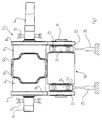
- Figure 1 illustrates a first embodiment of a rotary cutting unit including a rotary cutter and an anvil;
- Figure 2 illustrates an anvil according to the invention subjected to a load;
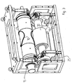
- Figure 3 illustrates a rotary cutting unit according to a second embodiment; and
- Figure 4 illustrates a rotary cutting unit according to a third embodiment;
- Figure 5 illustrates a rotary cutting unit according to a fourth embodiment; and
- Figure 6 illustrates a prior art anvil subjected to a load.
- Figure 1 shows a first embodiment of a
rotary cutting unit 2 according to the invention. Arotary cutter 4 is provided with a substantially circular-cylindrical hollow or solid body 6 having a cylindrical surface 8 and at least oneknife member 10 protruding from the surface 8. The radially peripheral part 12 of saidknife member 10 has a diameter larger than that of said surface 8. Therotary cutter 4 is arranged on or is an integral part of anarbour 14 extending axially from each side of therotary cutter 4 and being supported inbearings 15. Axially on each side of said surface 8, a pair ofannular abutment members 16 are provided. Theabutment members 16 have a diameter larger than that of said surface 8, in order to allow abutment against ananvil 18. - The
anvil 18 includes anaxle 19, ananvil portion 20 and a pair ofload transmitting portions 22. Theanvil portion 20 is adapted to cooperate with theknife member 10 of the rotary cutter 6, whereas theload transmitting portions 22 are adapted to abut saidabutment surfaces 16 of the rotary cutter 6. - Furthermore, the
abutment members 16 have a diameter which is substantially the same as the radially peripheral part 12 of saidknife member 10. - Axially on each side of the
anvil portion 20, theaxle 19 is rotatably arranged inbearings 23, each surrounded by a non-rotaryload receiving member 24. Theload receiving members 24 are arranged axially inside theload transmitting portions 22, i.e., each load receiving portion is located axially between theanvil portion 20 and eachload transmitting portion 22. - An upward load is applied by a pair of
pneumatic cylinders 25 to theload receiving members 24. The load is transmitted further via theload transmitting portions 22 to theabutment members 16. - In Figure 2, an
anvil 18 having a greater axial extension than that of the anvil of Figure 1 is shown for a better understanding of the invention. Anupward load 28 is transmitted via theload transmitting portions 22 to theabutment members 16, the total upward load being greater than the weight of the anvil and sufficient to cause theanvil 18 to be bent towards therotary cutter 4, resulting in the cutting properties being improved especially in the axially central portions of the knife members 10 (e.g., see Figure 2). The load of course causes a counter directed force at the surface 8 which is transmitted to thebearings 15 to produceforce 26. The load causes the anvil to be bent slightly upwards as shown (exaggerated) by thebroken line 30. - The load applied by the pair of
pneumatic cylinders 25 is adjusted by performing a cutting operation and checking the cutting result. If the cutting result is not the desired, the pressure is increased or decreased, until the cut is uniform over the whole extension of therotary cutter 4 and theanvil 18. - The optimal cut will in fact be achieved when the
anvil 18 is straight, i.e. when theline 30 is straight, since theabutment members 16 and the knife members 12 protrude substantially to the same extent above the surface 8 and will have constant cutting properties along thewhole anvil portion 20. - Figure 3 shows a second embodiment of a rotary cutting unit. The anvil and the rotary cutter drums are long and are even more affected by gravity such that they are bent towards the ground. However, when the
load transmitting portions 22 exert pressure on theabutments members 16, theanvil 18 will be bent towards the rotary cutter 6. Thus, when the pressure has been adjusted such that the line 30 (see Figure 2) is straight, the cutting properties will be substantially equal over the whole extension of theknife members 10. - Thus, by exerting
pressure 28 on theload receiving members 24, it will be possible to utilise also such a centrally disposed knife member. - Alternatively, a knife member on a long rotary cutting drum may extend substantially from one side to the other of the cutting drum, with maintained cutting properties.
- Figure 4 shows a third embodiment of a
rotary cutting unit 2 having a rotary cutter 6 with a pair ofknife members 10 arranged axially separated. The anvil is divided into twoseparate anvil portions 20 corresponding to said knife members. - Figure 5 shows a fourth embodiment, according to which the rotary cutter 6 is provided with a three axially
adjacent knife members 10, whereas theanvil 18 is provided with asingle anvil portion 20 only. By means of such a rotary cutter, it is possible to cut three articles simultaneously. Of course, less or more than three knife members may be arranged in parallel. - Of course, only one or more than two
pneumatic cylinders 25 may be utilised. Alternatively or additionally, hydraulic cylinders or mechanical loading e.g., via spindles and wedges may be utilized.
Claims (9)
- A rotatable anvil for a rotary cutting unit, comprising:an axle;at least one anvil portion adapted to cooperate with a knife member of a rotary cutter;a pair of load transmitting portions adapted to abut a pair of abutment members of the rotary cutter and arranged adjacent respective axial ends of said at least one anvil portion; andload receiving members disposed axially between said at least one anvil portion and respective load transmitting portions, each load receiving member being connected by a bearing to the axle, wherein the axle is rotatable relative to the load receiving members.
- The rotatable anvil according to claim 1, wherein said at least one anvil portion consists of a single anvil portion.
- The rotatable anvil according to claim 1 wherein said at least one anvil portion comprises a plurality of axially spaced anvil portions.
- A rotary cutting unit comprising a rotary cutting drum and a rotatable anvil, arranged therebeneath;said cutting drum comprising at least one knife member disposed between a pair of axially spaced abutment members;said rotatable anvil comprising an axle, at least one anvil portion arranged opposite the at least one knife member, and a pair of load transmitting portions abutting respective ones of said abutment members, and load receiving members disposed between said at least one anvil portion and respective ones of said load transmitting members, each of said load receiving members connected to said axle by a bearing; anda load applying mechanism arranged to apply to the load receiving members a variable upward force.
- The rotary cutting unit according to claim 4 wherein said at least one knife member consists of a centrally-disposed knife member and said at least one anvil portion consists of a single anvil portion.
- The rotary cutting unit according to claim 4 wherein said at least one knife member comprises a plurality of axially spaced knife members, and said at least one anvil portion comprises a plurality of axially spaced anvil portions.
- The rotary cutting unit according to claim 4 wherein said at least one knife member comprises a plurality of axially spaced knife members, and said at least one anvil portion consists of a single anvil portion.
- The rotary cutting unit according to claim 4 wherein the load applying mechanism comprises fluid-actuated cylinders engaging respective load receiving members.
- A cutting method utilizing a rotary cutting unit that includes a rotary cutting drum and a rotatable anvil arranged therebeneath, the cutting drum carrying a knife structure; wherein items being cut are passed between the knife structure and an anvil portion of the anvil; the cutting drum including axially spaced abutment members engaging respective axially spaced load transmitting members of the anvil; the anvil including axially spaced load receiving members disposed axially between the anvil portion and respective load transmitting members, the method comprising the step of applying an upward force to each of the load receiving members during a cutting operation, wherein the total upward force exceeds the weight of the anvil.
Applications Claiming Priority (1)
| Application Number | Priority Date | Filing Date | Title |
|---|---|---|---|
| SE0401735A SE527556C2 (en) | 2004-07-02 | 2004-07-02 | A support roller for a rotary knife unit and a rotation knife unit with such a support roller |
Publications (2)
| Publication Number | Publication Date |
|---|---|
| EP1612011A1 true EP1612011A1 (en) | 2006-01-04 |
| EP1612011B1 EP1612011B1 (en) | 2010-11-03 |
Family
ID=32733759
Family Applications (1)
| Application Number | Title | Priority Date | Filing Date |
|---|---|---|---|
| EP20050010601 Expired - Lifetime EP1612011B1 (en) | 2004-07-02 | 2005-05-17 | Anvil for an rotary cutting unit and a rotary cutting unit having such anvil |
Country Status (9)
| Country | Link |
|---|---|
| US (1) | US7942088B2 (en) |
| EP (1) | EP1612011B1 (en) |
| JP (1) | JP5179709B2 (en) |
| KR (1) | KR101273305B1 (en) |
| CN (1) | CN100556629C (en) |
| AT (1) | ATE486701T1 (en) |
| DE (1) | DE602005024482D1 (en) |
| SE (1) | SE527556C2 (en) |
| WO (1) | WO2006004474A1 (en) |
Families Citing this family (27)
| Publication number | Priority date | Publication date | Assignee | Title |
|---|---|---|---|---|
| US7954307B2 (en) | 2006-01-31 | 2011-06-07 | R. A. Jones & Co. Inc. | Adjustable pouch forming, filling and sealing apparatus and methods |
| DE102006044610B4 (en) * | 2006-09-19 | 2008-11-20 | WINKLER+DüNNEBIER AG | Device for cutting and / or embossing a blank or a material web |
| US8992306B2 (en) * | 2007-07-30 | 2015-03-31 | Igt | Gaming system and method providing variable payback percentages |
| US8915786B2 (en) * | 2007-08-09 | 2014-12-23 | Igt | Gaming system and method providing simultaneous gaming with linked paytable events |
| IT1394271B1 (en) * | 2009-05-25 | 2012-06-06 | Ima Flavour S R L Ora Ima Ind S R L | COMPRESSION GROUP - ENGRAVING - ROLLER CUTTING |
| JP5590899B2 (en) * | 2010-02-01 | 2014-09-17 | ユニ・チャーム株式会社 | Rotary processing equipment |
| US8863627B2 (en) | 2011-03-18 | 2014-10-21 | The Procter & Gamble Company | Anvil roll system and method |
| US8821149B2 (en) | 2011-05-05 | 2014-09-02 | Kimberly-Clark Worldwide, Inc. | Web treatment apparatus having center bearer ring |
| JP5806874B2 (en) * | 2011-07-29 | 2015-11-10 | ユニ・チャーム株式会社 | Absorbent article workpiece cutter device |
| DE102012208604A1 (en) | 2012-05-23 | 2013-11-28 | Hauni Maschinenbau Ag | Device for cutting filter rods |
| JP5942819B2 (en) * | 2012-11-28 | 2016-06-29 | 王子ホールディングス株式会社 | Cutting device and method for manufacturing disposable diaper |
| DE202013001956U1 (en) | 2013-02-28 | 2014-06-05 | Oil Clear Europe Ltd. | Apparatus for making an oil absorbing article |
| CN103231417B (en) * | 2013-05-08 | 2014-12-10 | 王振明 | Rolling forming die for disposable hygiene product |
| CN106255577B (en) * | 2014-04-03 | 2018-08-31 | 山特维克知识产权股份有限公司 | High-performance rotary cutting apparatus for the profile with straight edge |
| US10000302B2 (en) * | 2014-11-28 | 2018-06-19 | Paul W. Kawoczka | Method of forming a stack of cosmetic pads |
| ITUB20153933A1 (en) * | 2015-09-28 | 2017-03-28 | Cartes S R L | Apparatus for processing a flexible material. |
| ES2675850T3 (en) * | 2015-10-06 | 2018-07-13 | Sandvik Intellectual Property Ab | Rotary cutting device with an integrated monitoring unit |
| JP6148418B1 (en) | 2016-02-24 | 2017-06-14 | 日本タングステン株式会社 | Roll for rotary cutter and rotary cutter |
| US11292146B2 (en) | 2016-07-25 | 2022-04-05 | International Cutting Die, Inc. | Cutting apparatus for minimizing deflection of a die cutter assembly |
| RS63391B1 (en) * | 2016-11-15 | 2022-08-31 | Mespack Cloud Llc | BAG CUTTING MACHINE WITH MOLDED OUTER EDGE, METHOD AND BAG |
| JP7085914B2 (en) * | 2017-08-07 | 2022-06-17 | Mmcリョウテック株式会社 | Rotary die cutter |
| JP7079549B2 (en) * | 2018-01-18 | 2022-06-02 | 大阪シーリング印刷株式会社 | Label continuum, rotary die-cutting device and cutting method using it |
| USD958879S1 (en) * | 2020-02-27 | 2022-07-26 | Jiunchen Technology Co., Ltd. | Holder for roller paper cutter |
| USD950641S1 (en) * | 2020-02-27 | 2022-05-03 | Jiunchen Technology Co., Ltd. | Holder for roller paper cutter |
| IT202000025687A1 (en) * | 2020-10-29 | 2022-04-29 | V Shapes S R L | CUTTING UNIT FOR THE CREATION OF SINGLE-DOSE PACKS |
| BR112023017932A2 (en) * | 2021-03-08 | 2023-12-12 | Hyperion Materials & Tech Inc | ROTARY CUTTING UNIT |
| US20240316815A1 (en) * | 2023-03-22 | 2024-09-26 | Sun Automation, Inc. | Rotary Die Cutting Deflection Reducing Apparatus and Method for Corrugated Article Converting |
Citations (4)
| Publication number | Priority date | Publication date | Assignee | Title |
|---|---|---|---|---|
| US4381688A (en) * | 1979-05-24 | 1983-05-03 | The Stampiton Group Of Companies Limited | Cutter for rotary cutting machine |
| US5174185A (en) * | 1989-07-21 | 1992-12-29 | Wilhelm Aichele | Rotary cutting device for material webs |
| EP0899068A2 (en) * | 1997-08-23 | 1999-03-03 | Kocher + Beck GmbH + Co. Rotationsstanztechnik KG | Apparatus for punching labels and the like |
| US6244148B1 (en) | 1998-07-29 | 2001-06-12 | Aichele Werkzeuge Gmbh | Cutting device |
Family Cites Families (18)
| Publication number | Priority date | Publication date | Assignee | Title |
|---|---|---|---|---|
| US1984913A (en) * | 1933-06-17 | 1934-12-18 | United Eng Foundry Co | Flying shear |
| FR1502646A (en) * | 1966-03-31 | 1967-11-24 | Gillette France | Play compensating bearing |
| US4205596A (en) * | 1978-05-15 | 1980-06-03 | W. R. Chestnut Engineering, Inc. | Rotary die cutting device |
| DE2912458A1 (en) * | 1979-03-29 | 1980-10-09 | Winkler Duennebier Kg Masch | ROTATIONAL PUNCHING AGAINST THE CUTTER ROLLER SUPPORTED |
| DE3229948A1 (en) * | 1982-08-12 | 1984-02-16 | Schober GmbH, 7147 Eberdingen | Cutting roll |
| US4576219A (en) * | 1982-10-22 | 1986-03-18 | Certech Incorporated | Molten metals filter apparatus |
| DE3634198A1 (en) * | 1986-10-08 | 1988-04-21 | Peters W Maschf | CUTTER |
| CH673623A5 (en) * | 1987-06-19 | 1990-03-30 | Grapha Holding Ag | |
| GB8822328D0 (en) * | 1988-09-22 | 1988-10-26 | Stoddard Sekers Int | Pressure roller assembly |
| AU7859491A (en) * | 1990-05-10 | 1991-11-27 | Byron L. Buck | Rotary die cutting system for sheet material |
| JP3076069B2 (en) * | 1991-01-10 | 2000-08-14 | 日本石油化学株式会社 | Method and apparatus for producing perforated film |
| US5156076A (en) * | 1991-05-21 | 1992-10-20 | Rosemann Richard R | Radially adjustable anvil roll assembly for a rotary die cutting press |
| FR2684913B1 (en) * | 1991-12-16 | 1996-02-02 | Umat | ROTARY CUTTING APPARATUS. |
| US5498148A (en) * | 1994-08-10 | 1996-03-12 | Recot, Inc. | Apparatus for forming sheets of material having a uniform thickness and cutting individual portions therefrom |
| JP2981405B2 (en) * | 1994-10-17 | 1999-11-22 | 旭マシナリー株式会社 | Rotary cutter |
| US5498433A (en) * | 1995-04-18 | 1996-03-12 | Recot, Inc. | Apparatus and process for forming sheets of material having a uniform thickness |
| JP2002096290A (en) * | 2000-09-21 | 2002-04-02 | Kao Corp | Roll type cutting device |
| US7299729B2 (en) * | 2001-05-23 | 2007-11-27 | Cox William A | Rotary die module |
-
2004
- 2004-07-02 SE SE0401735A patent/SE527556C2/en unknown
-
2005
- 2005-05-16 CN CNB2005800203950A patent/CN100556629C/en not_active Expired - Lifetime
- 2005-05-16 WO PCT/SE2005/000696 patent/WO2006004474A1/en not_active Ceased
- 2005-05-16 KR KR1020067025225A patent/KR101273305B1/en not_active Expired - Lifetime
- 2005-05-17 AT AT05010601T patent/ATE486701T1/en not_active IP Right Cessation
- 2005-05-17 DE DE200560024482 patent/DE602005024482D1/en not_active Expired - Lifetime
- 2005-05-17 EP EP20050010601 patent/EP1612011B1/en not_active Expired - Lifetime
- 2005-06-24 US US11/165,485 patent/US7942088B2/en active Active
- 2005-06-30 JP JP2005191974A patent/JP5179709B2/en not_active Expired - Lifetime
Patent Citations (4)
| Publication number | Priority date | Publication date | Assignee | Title |
|---|---|---|---|---|
| US4381688A (en) * | 1979-05-24 | 1983-05-03 | The Stampiton Group Of Companies Limited | Cutter for rotary cutting machine |
| US5174185A (en) * | 1989-07-21 | 1992-12-29 | Wilhelm Aichele | Rotary cutting device for material webs |
| EP0899068A2 (en) * | 1997-08-23 | 1999-03-03 | Kocher + Beck GmbH + Co. Rotationsstanztechnik KG | Apparatus for punching labels and the like |
| US6244148B1 (en) | 1998-07-29 | 2001-06-12 | Aichele Werkzeuge Gmbh | Cutting device |
Also Published As
| Publication number | Publication date |
|---|---|
| SE527556C2 (en) | 2006-04-11 |
| CN1972786A (en) | 2007-05-30 |
| SE0401735L (en) | 2006-01-03 |
| US7942088B2 (en) | 2011-05-17 |
| CN100556629C (en) | 2009-11-04 |
| EP1612011B1 (en) | 2010-11-03 |
| ATE486701T1 (en) | 2010-11-15 |
| US20060048616A1 (en) | 2006-03-09 |
| DE602005024482D1 (en) | 2010-12-16 |
| KR101273305B1 (en) | 2013-06-11 |
| KR20070020262A (en) | 2007-02-20 |
| SE0401735D0 (en) | 2004-07-02 |
| WO2006004474A1 (en) | 2006-01-12 |
| JP2006015482A (en) | 2006-01-19 |
| JP5179709B2 (en) | 2013-04-10 |
Similar Documents
| Publication | Publication Date | Title |
|---|---|---|
| EP1612011B1 (en) | Anvil for an rotary cutting unit and a rotary cutting unit having such anvil | |
| WO2022263324A1 (en) | Drum brake | |
| US5855446A (en) | Hydraulic clamp bushing having sigma shaped bushing ends | |
| US4452347A (en) | Brake spider | |
| RU99116302A (en) | CUTTER FOR ROTARY PRINTING MACHINE | |
| EP2962865B1 (en) | Hub assembly, in particular for dual wheels | |
| US4509396A (en) | Apparatus for making holes in thick stacks of paper | |
| EP1655117B1 (en) | An anvil for a rotary cutting unit and a rotary cutting unit having an anvil | |
| MX2011000997A (en) | Force transmitting assembly. | |
| CN102699368A (en) | Chuck | |
| EP0205659A2 (en) | Vehicle brake support | |
| EP2034215A1 (en) | Transmission chain | |
| WO2020247991A1 (en) | Omnidirectional wheel hub drive | |
| IE851420L (en) | Coupling for drilling shank | |
| EP0205732A2 (en) | Vehicle axle and brake support assembly | |
| EP2877341B1 (en) | Separation device for separating substances having different flowabilities | |
| EP0205664A2 (en) | Brake support assembly | |
| EP2128048A1 (en) | Brake roller insert, brake roller and roller conveyor | |
| US9669561B2 (en) | Web slitter with flexible wall blade mounting | |
| JP6912986B2 (en) | Brake caliper device | |
| DE102008019531B3 (en) | Drum brake has stationary brake anchor plate and brake drum, where two bridging sections are provided, and each of two lever segments is held at end pivoted at fulcrum pin | |
| JP7686768B2 (en) | Rotary cutting unit | |
| MXPA06006870A (en) | Roll as well as a spacer ring therefor. | |
| GB1589002A (en) | Expander for internal shoe drum brakes | |
| NL2001635C2 (en) | Rotating device provided with rollers with interchangeable sleeves. |
Legal Events
| Date | Code | Title | Description |
|---|---|---|---|
| PUAI | Public reference made under article 153(3) epc to a published international application that has entered the european phase |
Free format text: ORIGINAL CODE: 0009012 |
|
| AK | Designated contracting states |
Kind code of ref document: A1 Designated state(s): AT BE BG CH CY CZ DE DK EE ES FI FR GB GR HU IE IS IT LI LT LU MC NL PL PT RO SE SI SK TR |
|
| AX | Request for extension of the european patent |
Extension state: AL BA HR LV MK YU |
|
| 17P | Request for examination filed |
Effective date: 20060704 |
|
| AKX | Designation fees paid |
Designated state(s): AT BE BG CH CY CZ DE DK EE ES FI FR GB GR HU IE IS IT LI LT LU MC NL PL PT RO SE SI SK TR |
|
| 17Q | First examination report despatched |
Effective date: 20080424 |
|
| GRAP | Despatch of communication of intention to grant a patent |
Free format text: ORIGINAL CODE: EPIDOSNIGR1 |
|
| GRAS | Grant fee paid |
Free format text: ORIGINAL CODE: EPIDOSNIGR3 |
|
| GRAA | (expected) grant |
Free format text: ORIGINAL CODE: 0009210 |
|
| AK | Designated contracting states |
Kind code of ref document: B1 Designated state(s): AT BE BG CH CY CZ DE DK EE ES FI FR GB GR HU IE IS IT LI LT LU MC NL PL PT RO SE SI SK TR |
|
| REG | Reference to a national code |
Ref country code: GB Ref legal event code: FG4D |
|
| REG | Reference to a national code |
Ref country code: CH Ref legal event code: EP |
|
| REG | Reference to a national code |
Ref country code: IE Ref legal event code: FG4D |
|
| REF | Corresponds to: |
Ref document number: 602005024482 Country of ref document: DE Date of ref document: 20101216 Kind code of ref document: P |
|
| REG | Reference to a national code |
Ref country code: NL Ref legal event code: VDEP Effective date: 20101103 |
|
| LTIE | Lt: invalidation of european patent or patent extension |
Effective date: 20101103 |
|
| PG25 | Lapsed in a contracting state [announced via postgrant information from national office to epo] |
Ref country code: LT Free format text: LAPSE BECAUSE OF FAILURE TO SUBMIT A TRANSLATION OF THE DESCRIPTION OR TO PAY THE FEE WITHIN THE PRESCRIBED TIME-LIMIT Effective date: 20101103 |
|
| PG25 | Lapsed in a contracting state [announced via postgrant information from national office to epo] |
Ref country code: SE Free format text: LAPSE BECAUSE OF FAILURE TO SUBMIT A TRANSLATION OF THE DESCRIPTION OR TO PAY THE FEE WITHIN THE PRESCRIBED TIME-LIMIT Effective date: 20101103 Ref country code: FI Free format text: LAPSE BECAUSE OF FAILURE TO SUBMIT A TRANSLATION OF THE DESCRIPTION OR TO PAY THE FEE WITHIN THE PRESCRIBED TIME-LIMIT Effective date: 20101103 Ref country code: PT Free format text: LAPSE BECAUSE OF FAILURE TO SUBMIT A TRANSLATION OF THE DESCRIPTION OR TO PAY THE FEE WITHIN THE PRESCRIBED TIME-LIMIT Effective date: 20110303 Ref country code: BG Free format text: LAPSE BECAUSE OF FAILURE TO SUBMIT A TRANSLATION OF THE DESCRIPTION OR TO PAY THE FEE WITHIN THE PRESCRIBED TIME-LIMIT Effective date: 20110203 Ref country code: NL Free format text: LAPSE BECAUSE OF FAILURE TO SUBMIT A TRANSLATION OF THE DESCRIPTION OR TO PAY THE FEE WITHIN THE PRESCRIBED TIME-LIMIT Effective date: 20101103 Ref country code: SI Free format text: LAPSE BECAUSE OF FAILURE TO SUBMIT A TRANSLATION OF THE DESCRIPTION OR TO PAY THE FEE WITHIN THE PRESCRIBED TIME-LIMIT Effective date: 20101103 Ref country code: AT Free format text: LAPSE BECAUSE OF FAILURE TO SUBMIT A TRANSLATION OF THE DESCRIPTION OR TO PAY THE FEE WITHIN THE PRESCRIBED TIME-LIMIT Effective date: 20101103 Ref country code: IS Free format text: LAPSE BECAUSE OF FAILURE TO SUBMIT A TRANSLATION OF THE DESCRIPTION OR TO PAY THE FEE WITHIN THE PRESCRIBED TIME-LIMIT Effective date: 20110303 |
|
| PG25 | Lapsed in a contracting state [announced via postgrant information from national office to epo] |
Ref country code: GR Free format text: LAPSE BECAUSE OF FAILURE TO SUBMIT A TRANSLATION OF THE DESCRIPTION OR TO PAY THE FEE WITHIN THE PRESCRIBED TIME-LIMIT Effective date: 20110204 |
|
| PG25 | Lapsed in a contracting state [announced via postgrant information from national office to epo] |
Ref country code: EE Free format text: LAPSE BECAUSE OF FAILURE TO SUBMIT A TRANSLATION OF THE DESCRIPTION OR TO PAY THE FEE WITHIN THE PRESCRIBED TIME-LIMIT Effective date: 20101103 Ref country code: BE Free format text: LAPSE BECAUSE OF FAILURE TO SUBMIT A TRANSLATION OF THE DESCRIPTION OR TO PAY THE FEE WITHIN THE PRESCRIBED TIME-LIMIT Effective date: 20101103 Ref country code: ES Free format text: LAPSE BECAUSE OF FAILURE TO SUBMIT A TRANSLATION OF THE DESCRIPTION OR TO PAY THE FEE WITHIN THE PRESCRIBED TIME-LIMIT Effective date: 20110214 Ref country code: CZ Free format text: LAPSE BECAUSE OF FAILURE TO SUBMIT A TRANSLATION OF THE DESCRIPTION OR TO PAY THE FEE WITHIN THE PRESCRIBED TIME-LIMIT Effective date: 20101103 |
|
| PG25 | Lapsed in a contracting state [announced via postgrant information from national office to epo] |
Ref country code: RO Free format text: LAPSE BECAUSE OF FAILURE TO SUBMIT A TRANSLATION OF THE DESCRIPTION OR TO PAY THE FEE WITHIN THE PRESCRIBED TIME-LIMIT Effective date: 20101103 Ref country code: DK Free format text: LAPSE BECAUSE OF FAILURE TO SUBMIT A TRANSLATION OF THE DESCRIPTION OR TO PAY THE FEE WITHIN THE PRESCRIBED TIME-LIMIT Effective date: 20101103 Ref country code: PL Free format text: LAPSE BECAUSE OF FAILURE TO SUBMIT A TRANSLATION OF THE DESCRIPTION OR TO PAY THE FEE WITHIN THE PRESCRIBED TIME-LIMIT Effective date: 20101103 Ref country code: SK Free format text: LAPSE BECAUSE OF FAILURE TO SUBMIT A TRANSLATION OF THE DESCRIPTION OR TO PAY THE FEE WITHIN THE PRESCRIBED TIME-LIMIT Effective date: 20101103 |
|
| PLBE | No opposition filed within time limit |
Free format text: ORIGINAL CODE: 0009261 |
|
| STAA | Information on the status of an ep patent application or granted ep patent |
Free format text: STATUS: NO OPPOSITION FILED WITHIN TIME LIMIT |
|
| 26N | No opposition filed |
Effective date: 20110804 |
|
| REG | Reference to a national code |
Ref country code: DE Ref legal event code: R097 Ref document number: 602005024482 Country of ref document: DE Effective date: 20110804 |
|
| PG25 | Lapsed in a contracting state [announced via postgrant information from national office to epo] |
Ref country code: MC Free format text: LAPSE BECAUSE OF NON-PAYMENT OF DUE FEES Effective date: 20110531 |
|
| REG | Reference to a national code |
Ref country code: CH Ref legal event code: PL |
|
| PG25 | Lapsed in a contracting state [announced via postgrant information from national office to epo] |
Ref country code: LI Free format text: LAPSE BECAUSE OF NON-PAYMENT OF DUE FEES Effective date: 20110531 Ref country code: CH Free format text: LAPSE BECAUSE OF NON-PAYMENT OF DUE FEES Effective date: 20110531 |
|
| REG | Reference to a national code |
Ref country code: IE Ref legal event code: MM4A |
|
| PG25 | Lapsed in a contracting state [announced via postgrant information from national office to epo] |
Ref country code: IE Free format text: LAPSE BECAUSE OF NON-PAYMENT OF DUE FEES Effective date: 20110517 |
|
| PG25 | Lapsed in a contracting state [announced via postgrant information from national office to epo] |
Ref country code: LU Free format text: LAPSE BECAUSE OF NON-PAYMENT OF DUE FEES Effective date: 20110517 Ref country code: CY Free format text: LAPSE BECAUSE OF FAILURE TO SUBMIT A TRANSLATION OF THE DESCRIPTION OR TO PAY THE FEE WITHIN THE PRESCRIBED TIME-LIMIT Effective date: 20101103 |
|
| PG25 | Lapsed in a contracting state [announced via postgrant information from national office to epo] |
Ref country code: TR Free format text: LAPSE BECAUSE OF FAILURE TO SUBMIT A TRANSLATION OF THE DESCRIPTION OR TO PAY THE FEE WITHIN THE PRESCRIBED TIME-LIMIT Effective date: 20101103 |
|
| PG25 | Lapsed in a contracting state [announced via postgrant information from national office to epo] |
Ref country code: HU Free format text: LAPSE BECAUSE OF FAILURE TO SUBMIT A TRANSLATION OF THE DESCRIPTION OR TO PAY THE FEE WITHIN THE PRESCRIBED TIME-LIMIT Effective date: 20101103 |
|
| REG | Reference to a national code |
Ref country code: FR Ref legal event code: PLFP Year of fee payment: 12 |
|
| REG | Reference to a national code |
Ref country code: FR Ref legal event code: PLFP Year of fee payment: 13 |
|
| REG | Reference to a national code |
Ref country code: FR Ref legal event code: PLFP Year of fee payment: 14 |
|
| REG | Reference to a national code |
Ref country code: GB Ref legal event code: 732E Free format text: REGISTERED BETWEEN 20180913 AND 20180919 |
|
| REG | Reference to a national code |
Ref country code: DE Ref legal event code: R082 Ref document number: 602005024482 Country of ref document: DE Representative=s name: KRAUS & WEISERT PATENTANWAELTE PARTGMBB, DE Ref country code: DE Ref legal event code: R081 Ref document number: 602005024482 Country of ref document: DE Owner name: SANDVIK HYPERION AB, SE Free format text: FORMER OWNER: SANDVIK INTELLECTUAL PROPERTY AB, SANDVIKEN, SE Ref country code: DE Ref legal event code: R081 Ref document number: 602005024482 Country of ref document: DE Owner name: HYPERION MATERIALS & TECHNOLOGIES (SWEDEN) AB, SE Free format text: FORMER OWNER: SANDVIK INTELLECTUAL PROPERTY AB, SANDVIKEN, SE |
|
| REG | Reference to a national code |
Ref country code: DE Ref legal event code: R081 Ref document number: 602005024482 Country of ref document: DE Owner name: HYPERION MATERIALS & TECHNOLOGIES (SWEDEN) AB, SE Free format text: FORMER OWNER: SANDVIK HYPERION AB, STOCKHOLM, SE Ref country code: DE Ref legal event code: R082 Ref document number: 602005024482 Country of ref document: DE Representative=s name: KRAUS & WEISERT PATENTANWAELTE PARTGMBB, DE |
|
| PGFP | Annual fee paid to national office [announced via postgrant information from national office to epo] |
Ref country code: GB Payment date: 20240527 Year of fee payment: 20 |
|
| PGFP | Annual fee paid to national office [announced via postgrant information from national office to epo] |
Ref country code: DE Payment date: 20240530 Year of fee payment: 20 |
|
| PGFP | Annual fee paid to national office [announced via postgrant information from national office to epo] |
Ref country code: FR Payment date: 20240527 Year of fee payment: 20 |
|
| PGFP | Annual fee paid to national office [announced via postgrant information from national office to epo] |
Ref country code: IT Payment date: 20240521 Year of fee payment: 20 |
|
| REG | Reference to a national code |
Ref country code: DE Ref legal event code: R071 Ref document number: 602005024482 Country of ref document: DE |
|
| REG | Reference to a national code |
Ref country code: GB Ref legal event code: PE20 Expiry date: 20250516 |
|
| PG25 | Lapsed in a contracting state [announced via postgrant information from national office to epo] |
Ref country code: GB Free format text: LAPSE BECAUSE OF EXPIRATION OF PROTECTION Effective date: 20250516 |