EP1610995B1 - Train de roulement pour vehicule sur rails a meilleure suspension transversale - Google Patents
Train de roulement pour vehicule sur rails a meilleure suspension transversale Download PDFInfo
- Publication number
- EP1610995B1 EP1610995B1 EP04726112A EP04726112A EP1610995B1 EP 1610995 B1 EP1610995 B1 EP 1610995B1 EP 04726112 A EP04726112 A EP 04726112A EP 04726112 A EP04726112 A EP 04726112A EP 1610995 B1 EP1610995 B1 EP 1610995B1
- Authority
- EP
- European Patent Office
- Prior art keywords
- running gear
- suspension
- transversal
- gear according
- frame
- Prior art date
- Legal status (The legal status is an assumption and is not a legal conclusion. Google has not performed a legal analysis and makes no representation as to the accuracy of the status listed.)
- Expired - Lifetime
Links
- 239000000725 suspension Substances 0.000 title claims abstract description 63
- 238000013016 damping Methods 0.000 claims abstract description 9
- 239000003381 stabilizer Substances 0.000 claims description 7
- 238000006073 displacement reaction Methods 0.000 claims 1
- 230000033001 locomotion Effects 0.000 abstract description 4
- 238000005096 rolling process Methods 0.000 abstract description 4
- 230000003993 interaction Effects 0.000 abstract 1
- 238000010276 construction Methods 0.000 description 2
- 230000000750 progressive effect Effects 0.000 description 2
- 230000008878 coupling Effects 0.000 description 1
- 238000010168 coupling process Methods 0.000 description 1
- 238000005859 coupling reaction Methods 0.000 description 1
- 230000000694 effects Effects 0.000 description 1
- 238000005516 engineering process Methods 0.000 description 1
- 230000003071 parasitic effect Effects 0.000 description 1
- 230000000149 penetrating effect Effects 0.000 description 1
Images

Classifications
-
- B—PERFORMING OPERATIONS; TRANSPORTING
- B61—RAILWAYS
- B61F—RAIL VEHICLE SUSPENSIONS, e.g. UNDERFRAMES, BOGIES OR ARRANGEMENTS OF WHEEL AXLES; RAIL VEHICLES FOR USE ON TRACKS OF DIFFERENT WIDTH; PREVENTING DERAILING OF RAIL VEHICLES; WHEEL GUARDS, OBSTRUCTION REMOVERS OR THE LIKE FOR RAIL VEHICLES
- B61F5/00—Constructional details of bogies; Connections between bogies and vehicle underframes; Arrangements or devices for adjusting or allowing self-adjustment of wheel axles or bogies when rounding curves
- B61F5/02—Arrangements permitting limited transverse relative movements between vehicle underframe or bolster and bogie; Connections between underframes and bogies
- B61F5/04—Bolster supports or mountings
- B61F5/10—Bolster supports or mountings incorporating fluid springs
-
- B—PERFORMING OPERATIONS; TRANSPORTING
- B61—RAILWAYS
- B61F—RAIL VEHICLE SUSPENSIONS, e.g. UNDERFRAMES, BOGIES OR ARRANGEMENTS OF WHEEL AXLES; RAIL VEHICLES FOR USE ON TRACKS OF DIFFERENT WIDTH; PREVENTING DERAILING OF RAIL VEHICLES; WHEEL GUARDS, OBSTRUCTION REMOVERS OR THE LIKE FOR RAIL VEHICLES
- B61F5/00—Constructional details of bogies; Connections between bogies and vehicle underframes; Arrangements or devices for adjusting or allowing self-adjustment of wheel axles or bogies when rounding curves
- B61F5/02—Arrangements permitting limited transverse relative movements between vehicle underframe or bolster and bogie; Connections between underframes and bogies
- B61F5/04—Bolster supports or mountings
- B61F5/12—Bolster supports or mountings incorporating dampers
- B61F5/127—Bolster supports or mountings incorporating dampers with fluid as a damping medium
-
- B—PERFORMING OPERATIONS; TRANSPORTING
- B61—RAILWAYS
- B61F—RAIL VEHICLE SUSPENSIONS, e.g. UNDERFRAMES, BOGIES OR ARRANGEMENTS OF WHEEL AXLES; RAIL VEHICLES FOR USE ON TRACKS OF DIFFERENT WIDTH; PREVENTING DERAILING OF RAIL VEHICLES; WHEEL GUARDS, OBSTRUCTION REMOVERS OR THE LIKE FOR RAIL VEHICLES
- B61F5/00—Constructional details of bogies; Connections between bogies and vehicle underframes; Arrangements or devices for adjusting or allowing self-adjustment of wheel axles or bogies when rounding curves
- B61F5/02—Arrangements permitting limited transverse relative movements between vehicle underframe or bolster and bogie; Connections between underframes and bogies
- B61F5/22—Guiding of the vehicle underframes with respect to the bogies
Definitions
- the invention relates to a chassis for a rail vehicle with at least one wheelset, a chassis supported by a primary suspension on the wheelset, a secondary suspension for supporting a car body on the chassis frame, a tilting device for controlled tilting of the car body about a longitudinal axis of the rail vehicle and a transverse suspension.
- the air springs of air-suspension rail vehicles are usually associated with transverse springs and transverse dampers.
- the transverse springs and transverse dampers are usually arranged in a longitudinally eccentric or deep central position. Both positions usually lead to unfavorable dynamic behavior.
- the arrangement at a longitudinally eccentric position leads to parasitic torsional vibrations and to a reduction in the efficiency of the suspension elements.
- the deep central position increases the rolling motions and thus reduces the damping of the lateral and roll movement.
- a bogie chassis for a rail vehicle with a biaxial drive known.
- the drive is attached via a primary suspension to a frame, on which with interposition a secondary suspension is arranged transversely to the direction of travel pendulum carrier.
- the pendulum carrier is pivotally connected about an axis extending in the vehicle longitudinal axis with a transverse, the car body bearing, tiltable cross member, which is frame-shaped and has two transversely aligned to the direction of traverse cross member, which are arranged in front of and behind the pendulum carrier.
- the truss cross members are supported in the direction of travel on the pendulum carrier and arranged transversely to the direction of travel on this displaceable.
- the US 3,877,389 shows a two-story passenger coach with two-axle chassis, each having a supported via a primary suspension to the wheelsets chassis frame and a secondary suspension for supporting the car body on the chassis frame.
- the trolleys are also each provided with a transverse suspension, which are arranged above the secondary suspension and below the bottom of the upper car body deck in a bachelorkasten formatraum.
- the present invention has for its object to provide a chassis of the type mentioned, which does not have the above-mentioned disadvantages of conventional air-suspension rail vehicles. It is to be created a generic suspension that at Compact design offers the highest possible functionality with very good suspension comfort.
- the transverse suspension or transverse damping is arranged above the secondary suspension and below the floor of the car body. Further, an intermediate support is arranged above the secondary suspension, on which an actuator for adjusting the inclination of the car body relative to the chassis frame is supported.
- the intermediate carrier has a recess through which protrudes a transverse suspension or transverse damping supporting support.
- the transverse suspension is preferably arranged in the middle of the chassis. Through this high and central arrangement of the transverse suspension or transverse damping transverse, rolling and rolling movements can be controlled better and with less mutual interference. Due to the central (central) arrangement of the transverse suspension or transverse damping no coupling of the transverse and torsional vibrations of the chassis takes place, which increases the efficiency of the suspension elements and allows for active control systems a higher control quality.
- the chassis according to the invention offers maximum functionality and performance with extremely compact design. It is characterized by a relatively simple construction and can therefore be implemented inexpensively.
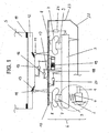
- the landing gear shown in Fig. 1 has a plurality of wheelsets, of which only one axle section 1 is sketched with a rail wheel 2 of a wheelset for the sake of simplicity.
- the wheelsets are each provided with brakes (not shown), for example disc brakes, and guided in axle guides (not shown).
- the chassis also consists of a chassis frame 3, which is supported via a primary suspension 4 in the form of coil springs on the wheel.
- a primary suspension 4 in the form of coil springs on the wheel.
- the car body 5 of a rail vehicle for example, the car body of a long-distance train for passenger transport via a secondary suspension 6 is supported.
- the secondary suspension consists of at least two suspension units, which are designed as air springs 6.
- the air springs 6 each have an air spring bellows 7, an additional volume 8 and an auxiliary spring 9 acting in the vertical direction.
- the components 7 to 9 of the air springs 6 are preferably arranged as close to each other as possible. In this way, long connecting lines can be avoided, the possibly lead to undesirable throttling effects or to a dynamic hardening at higher frequencies.
- the components 7 to 9 of the air springs 6 are arranged directly above one another.
- an intermediate carrier 10 is arranged in the form of a traverse, on which a known tilting device is mounted, by means of which the car body 5 can be inclined in particular controlled in cornering about its longitudinal axis.
- the arranged on the intermediate beam 10 tilting device preferably comprises four rollers 11 which are mounted in special brackets on the cross member 10. Of the four rollers only two rollers 11 are shown here.
- On the rollers 11 is a car body cross member 12 which has on its underside the rollers 11 associated roller conveyors 13.
- the roller conveyors 13 may be curved or convex. In the illustrated embodiment, they consist of substantially flat roller conveyors 13, which are inclined in different directions, so that their extensions intersect like the legs of a V at a point.
- the car body cross member 12 is connected via special connecting elements 14 to the car body 5.
- the rollers 11 and the roller conveyors 13 are arranged substantially symmetrically to the longitudinal center axis or vertical longitudinal center plane of the car body 5.
- an actuator 15 which may be, for example, an electromechanical, hydraulic or electro-hydraulic tilting actuator, in particular may be a double-acting hydraulic cylinder.
- a transverse damper 16 is arranged above the intermediate cross member 10.
- the transverse damper 16 is supported at one end to the intermediate cross member 10 and at the other end via a bracket 17 on the chassis frame 3.
- the transverse damper 16 may in particular be a semi-active transverse damper.
- the transverse damper 16 associated bracket 17 is disposed substantially centrally between the two air springs 6 and extends from the chassis frame 3 to a level above the air springs 6.
- the chassis frame 3 has two cross members.
- the transverse damper 16 supporting bracket 17 is connected to the two cross members of the chassis frame 3 and preferably formed by the longitudinal connection of the two cross member of the frame 3.
- Bracket 17 At this bracket 17 is also a progressive cross-spring 19 is mounted, which serves to limit the lateral relative path between the chassis frame 3 and intermediate beam 10 ("Holdoff-device") and is also supported on the intermediate beam 10.
- the progressively acting transverse spring 19 is arranged directly below the intermediate crosspiece 10.
- transverse spring 20 is disposed between the undercarriage frame 3 and the intermediate cross member 10, of which only one transverse spring is shown here.
- the transverse springs 20, on the chassis frame 3 and the intermediate beam 10 via Brackets are supported, are preferably arranged in frame niches.
- transverse damper 16 is arranged between two of the four rollers 11 of the tilting device. Between the other two rollers, the actuator 15 of the tilting device is arranged.
- a vertical damper 21 between the chassis frame 3 and the intermediate beam 10 is arranged in each case.
- one or two roll stabilizers 22 are present.
- the torsion bar of the roll stabilizer is mounted on the chassis frame 3, while the stabilizer arm (link member) 23 is articulated on the outside of the air springs 6 on the intermediate carrier 10.
- the exemplary embodiment shown schematically in FIG. 2 differs from the exemplary embodiment according to FIG. 1 in that, instead of the passively acting transverse springs and the passive transverse damper, an active transverse suspension is arranged above the intermediate cross member 10 and thus above the air springs 6 (secondary suspension).
- the active transverse suspension is formed here by two active transverse springs 24, 25, which are fastened to the upper end of the opening 18 of the intermediate cross member 10 penetrating bracket 17 and to the intermediate cross member 10. It is also possible, instead of two active transverse springs 24, 25 provide only an active transverse spring on the bracket 17.
- the holder 17 is in turn arranged in the longitudinal center plane of the car body 5 and fastened with its other end on the chassis frame 3.
- the car body 5 is also here with a tilting device Mistake. It can be seen that on the car body 5, a car body cross-member 12 is attached, which has arcuately curved roller conveyors 13 on its underside, via which the car body 5 rests on the rollers 11 mounted on the intermediate travers
- the invention thus provides a modular chassis, which is optionally equipped with the options active cross spring, semi-active transverse damper and tilting technology, without having to change the interface between the chassis and car body fundamentally or intervene in the car body structure.
Claims (21)
- Train de roulement pour un véhicule sur rails avec au moins un essieu, un châssis (3) de train de roulement reposant sur l'essieu par l'intermédiaire d'une suspension primaire (4), une suspension secondaire pour supporter une caisse de véhicule (5) sur le châssis du train de roulement, un dispositif d'inclinaison pour incliner de manière commandée la caisse de véhicule (5) autour d'un axe longitudinal du véhicule sur rails, et une suspension transversale (24, 25), dans lequel la suspension transversale (24, 25) ou un amortissement transversal (16) est agencé au-dessus de la suspension secondaire (6) et en dessous du bas de caisse de la caisse du véhicule (5), et dans lequel un support intermédiaire (10) est agencé au dessus de la suspension secondaire (6), support sur lequel s'appuie un organe d'ajustement (15) pour ajuster l'inclinaison de la caisse du véhicule (5) par rapport au châssis (3) du train de roulement, caractérisé en ce que le support intermédiaire (6) présente un évidement (18) que traverse un support (17) d'appui de la suspension transversale (24, 25) ou de l'amortissement transversal (16).
- Train de roulement selon la revendication 1, caractérisé en ce que la suspension secondaire (6) est formée par au moins deux blocs de suspension, la suspension transversale (24, 25) étant disposée sensiblement au milieu entre les blocs de suspension.
- Train de roulement selon la revendication 1 ou 2, caractérisé en ce que la suspension transversale (24, 25) s'appuie sur le châssis (3) du train de roulement par l'intermédiaire du support (17), le support (17) s'étendant à partir du châssis (3) du train de roulement et jusqu'à un niveau plus élevé que la suspension secondaire (6).
- Train de roulement selon la revendication 3, caractérisé en ce que le support (17) est disposé sensiblement au milieu entre deux blocs de suspension de la suspension secondaire (6).
- Train de roulement selon la revendication 3 ou 4, caractérisé en ce que le châssis (3) du train de roulement présente deux traverses, le support (17) de soutien de la suspension transversale étant relié aux deux traverses.
- Train de roulement selon la revendication 2 ou 4, caractérisé en ce que les blocs de suspension sont réalisés sous la forme de ressorts pneumatiques (6).
- Train de roulement selon la revendication 2, 4 ou 6, caractérisé en ce que les blocs de suspension présentent chacun un soufflet (7) de ressort pneumatique, un volume auxiliaire (8) et un ressort auxiliaire (9) travaillant dans le sens vertical.
- Train de roulement selon l'une des revendications 1 à 7, caractérisé en ce que l'amortissement transversal (16) est formé par un amortisseur transversal semi-actif.
- Train de roulement selon l'une des revendications 1 à 8, caractérisé en ce que la suspension transversale est formée par au moins un dispositif de suspension transversal (24, 25) actif ou semi-actif.
- Train de roulement selon l'une des revendications 1 à 9, caractérisé en ce qu'au moins un ressort transversal (20) est disposé chaque fois devant et derrière la suspension secondaire (6), par rapport à la direction de circulation du véhicule sur rails.
- Train de roulement selon la revendication 10, caractérisé en ce que les ressorts transversaux (20) sont chacun disposés dans la région de niches du châssis (3) du train de roulement.
- Train de roulement selon l'une des revendications 1 à 11, caractérisé en ce qu'au moins un stabilisateur de roulis (22) est monté sur le châssis (3) du train de roulement.
- Train de roulement selon l'une des revendications 1 à 12, caractérisé en ce que le dispositif d'inclinaison comprend au moins deux rouleaux (11) en contact avec des voies de roulement (13) courbes ou planes, inclinées en direction d'un point d'intersection, l'organe de réglage (15) pour fixer l'inclinaison de la caisse (5) du véhicule par rapport au châssis (3) du train de roulement étant disposé entre les rouleaux (11).
- Train de roulement selon la revendication 13, caractérisé en ce que les rouleaux (11) du dispositif d'inclinaison s'appuient sur le support intermédiaire (10).
- Train de roulement selon l'une des revendications 1 à 14, caractérisé en ce qu'un stabilisateur de roulis (22) est relié au support intermédiaire (10) par l'intermédiaire d'un organe de guidage (23).
- Train de roulement selon l'une des revendications 1 à 15, caractérisé en ce que la suspension transversale comprend au moins un ressort transversal à action progressive, qui limite un glissement latéral entre le châssis (3) du train de roulement et la caisse (5) du véhicule ou le support intermédiaire (10).
- Train de roulement selon l'une des revendications 1 à 16, caractérisé en ce qu'au moins un amortisseur vertical (21) est agencé parallèlement à la suspension secondaire.
- Train de roulement selon la revendication 17, caractérisé en ce que l'amortisseur vertical (21) est monté sur le châssis (3) de train de roulement et le support intermédiaire (10).
- Train de roulement selon la revendication 13 ou 14, caractérisé en ce que les chemins de roulement (13) sont réalisés sur une traverse (12) de la caisse du véhicule.
- Train de roulement selon la revendication 19, caractérisé en ce qu'une extrémité de l'organe de réglage (15) s'appuie sur la traverse (12) de la caisse du véhicule.
- Train de roulement selon la revendication 19 ou 20, caractérisé en ce que la traverse (12) de la caisse du véhicule est reliée à la caisse (5) du véhicule par l'intermédiaire d'éléments de liaison (14).
Priority Applications (1)
| Application Number | Priority Date | Filing Date | Title |
|---|---|---|---|
| PL04726112T PL1610995T3 (pl) | 2003-04-09 | 2004-04-07 | Podwozie dla pojazdu szynowego z ulepszonym resorowaniem poprzecznym |
Applications Claiming Priority (2)
| Application Number | Priority Date | Filing Date | Title |
|---|---|---|---|
| DE10316497A DE10316497A1 (de) | 2003-04-09 | 2003-04-09 | Fahrwerk für ein Schienenfahrzeug mit verbesserter Querfederung |
| PCT/EP2004/003733 WO2004089716A1 (fr) | 2003-04-09 | 2004-04-07 | Train de roulement pour vehicule sur rails a meilleure suspension transversale |
Publications (2)
| Publication Number | Publication Date |
|---|---|
| EP1610995A1 EP1610995A1 (fr) | 2006-01-04 |
| EP1610995B1 true EP1610995B1 (fr) | 2007-06-13 |
Family
ID=33154150
Family Applications (1)
| Application Number | Title | Priority Date | Filing Date |
|---|---|---|---|
| EP04726112A Expired - Lifetime EP1610995B1 (fr) | 2003-04-09 | 2004-04-07 | Train de roulement pour vehicule sur rails a meilleure suspension transversale |
Country Status (15)
| Country | Link |
|---|---|
| US (1) | US20070137515A1 (fr) |
| EP (1) | EP1610995B1 (fr) |
| JP (1) | JP4435152B2 (fr) |
| KR (1) | KR100980162B1 (fr) |
| CN (1) | CN100448725C (fr) |
| AT (1) | ATE364542T1 (fr) |
| CA (1) | CA2521332C (fr) |
| DE (2) | DE10316497A1 (fr) |
| DK (1) | DK1610995T3 (fr) |
| ES (1) | ES2288254T3 (fr) |
| NO (1) | NO328621B1 (fr) |
| PL (1) | PL1610995T3 (fr) |
| PT (1) | PT1610995E (fr) |
| RU (1) | RU2331536C2 (fr) |
| WO (1) | WO2004089716A1 (fr) |
Cited By (3)
| Publication number | Priority date | Publication date | Assignee | Title |
|---|---|---|---|---|
| DE102015112015B3 (de) * | 2015-07-23 | 2016-09-29 | Bombardier Transportation Gmbh | Luftfederanordnung für schienenfahrzeug und schienenfahrzeug mit luftfederanordnung |
| DE102015112012B3 (de) * | 2015-07-23 | 2016-12-01 | Bombardier Transportation Gmbh | Luftfederanordnung für Schienenfahrzeug und Schienenfahrzeug mit Luftfederanordnung |
| EP3144200A1 (fr) | 2015-09-17 | 2017-03-22 | Stadler Bussnang AG | Dispositif de ressort destine a la reception de forces transversales et vehicules sur rails comprenant un dispositif de ressort |
Families Citing this family (18)
| Publication number | Priority date | Publication date | Assignee | Title |
|---|---|---|---|---|
| JP2005132127A (ja) * | 2003-10-28 | 2005-05-26 | Hitachi Ltd | 鉄道車両および鉄道車両用台車 |
| ES2281997B1 (es) * | 2004-11-15 | 2008-08-16 | Excavaciones Y Demoliciones Bergantiños, S.L. | Sistema de ejes equipados con dyploris adaptable a cualquier ancho de via y con eje oscilante estibilizador para excavadoras y cargadoras adaptadas para la realizacion de trabajos y circulacion por via ferreas. |
| DE102009014866A1 (de) * | 2009-03-30 | 2010-10-28 | Bombardier Transportation Gmbh | Fahrzeug mit Wankkompensation |
| DE102009041109A1 (de) * | 2009-09-15 | 2011-03-24 | Bombardier Transportation Gmbh | Fahrzeug mit querweicher Ankopplung des Wagenkastens am Fahrwerk |
| AU2011294664B2 (en) * | 2010-08-25 | 2015-01-22 | Nippon Steel Corporation | System and method for estimating acceleration of vibration component in railcar |
| KR101388298B1 (ko) * | 2010-08-25 | 2014-04-22 | 신닛테츠스미킨 카부시키카이샤 | 철도 차량의 진동 억제 장치 |
| AT510492A1 (de) * | 2010-09-21 | 2012-04-15 | Siemens Ag Oesterreich | Gewichtsoptimierte anbindung des fahrwerks eines schienenfahrzeuges an einen wagenkasten |
| FR2987590B1 (fr) * | 2012-03-05 | 2014-11-28 | Alstom Transport Sa | Bogie pendulaire pour vehicule ferroviaire, vehicule et train correspondant |
| JP5912898B2 (ja) * | 2012-06-18 | 2016-04-27 | 川崎重工業株式会社 | 鉄道車両用台車 |
| DE102012105310A1 (de) * | 2012-06-19 | 2013-12-19 | Bombardier Transportation Gmbh | Fahrzeug mit einer Federeinrichtung mit vorgebbarer Querfedercharakteristik |
| EP2724912B1 (fr) * | 2012-10-24 | 2019-03-06 | Bombardier Transportation GmbH | Suspension de véhicule ferroviaire doté de moyens de commande de résistance au roulis |
| AT514029B1 (de) | 2013-01-22 | 2015-05-15 | Siemens Ag Oesterreich | Schienenfahrzeug mit Neigetechnik |
| EP3012172B1 (fr) * | 2013-06-19 | 2020-02-12 | Nippon Steel Corporation | Chariot de véhicule de chemin de fer |
| DE102014216965A1 (de) * | 2014-08-26 | 2016-03-03 | Siemens Aktiengesellschaft | Fahrwerk für ein Schienenfahrzeug |
| JP6450278B2 (ja) * | 2015-08-03 | 2019-01-09 | Kyb株式会社 | 鉄道車両用制振装置 |
| CN107985328A (zh) * | 2017-11-29 | 2018-05-04 | 中建空列(北京)科技有限公司 | 悬挂式空中轨道列车 |
| JP6951372B2 (ja) * | 2019-01-23 | 2021-10-20 | Kyb株式会社 | 鉄道車両用制振装置 |
| CN113479227A (zh) * | 2021-07-12 | 2021-10-08 | 上海工程技术大学 | 一种用于轨道车辆转向架的多方位缓冲器 |
Family Cites Families (26)
| Publication number | Priority date | Publication date | Assignee | Title |
|---|---|---|---|---|
| DE6606697U (de) * | 1967-07-22 | 1970-11-26 | Maschf Augsburg Nuernberg Ag | Federung fuer fahrzeuge, insbesondere schienenfahrzeuge |
| US3628465A (en) * | 1969-01-13 | 1971-12-21 | Dominion Foundries & Steel | Stabilizing high speed railway trucks |
| US3695186A (en) * | 1970-07-06 | 1972-10-03 | Budd Co | Lateral car stabilizing system |
| US3782294A (en) * | 1971-08-05 | 1974-01-01 | Rockwell International Corp | Articulated railway truck swinging bolster |
| US3877389A (en) * | 1974-02-19 | 1975-04-15 | Budd Co | Stabilizing roll control for pneumatic spring railway car |
| US4648326A (en) * | 1985-02-22 | 1987-03-10 | Lukens General Industries, Inc. | Radial axle railway truck with axle couplings at sides transversely interconnected with each other |
| DE3612797C1 (de) * | 1986-04-16 | 1987-08-20 | Messerschmitt Boelkow Blohm | Drehgestell fuer ein Schienenfahrzeug |
| DE19544030C2 (de) * | 1995-11-25 | 2001-05-31 | Daimler Chrysler Ag | Schienenfahrzeug mit einem Wagenkasten |
| FR2748439B1 (fr) * | 1996-05-07 | 1998-06-12 | Gec Alsthom Transport Sa | Bogie moteur |
| FR2748979B1 (fr) * | 1996-05-22 | 1998-07-10 | Gec Alsthom Transport Sa | Dispositif de pendulation de vehicules articules, rame de vehicules et vehicule comprenant un tel dispositif |
| FR2756241B1 (fr) * | 1996-11-25 | 2003-11-14 | Gec Alsthom Transport Sa | Dispositif de pendulation a bielles et bogie a pendulation a bielles |
| AT405166B (de) * | 1996-12-19 | 1999-06-25 | Siemens Sgp Verkehrstech Gmbh | Drehgestell-fahrwerk für ein schienenfahrzeug |
| US6131520A (en) * | 1997-04-07 | 2000-10-17 | Siemens Aktiengesellschaft | Rail vehicle |
| DK0888923T3 (da) * | 1997-07-01 | 2006-01-09 | Construcciones Y Aux De Ferroc | Strömsamlende anordning til vippende tog |
| WO1999038749A1 (fr) * | 1998-01-30 | 1999-08-05 | Buckeye Steel Castings Company | Traverse danseuse legere |
| DE19805895C1 (de) * | 1998-02-13 | 1999-07-08 | Abb Daimler Benz Transp | Schienenfahrzeug mit Verbindungseinrichtungen zwischen Wagenkasten und Fahrwerk |
| DE19815197C1 (de) * | 1998-04-04 | 1999-07-22 | Abb Daimler Benz Transp | Schienenfahrzeug mit einem verikalen Stützaktuator |
| DE19852639B4 (de) * | 1998-11-14 | 2004-10-07 | Daimlerchrysler Ag | Stromabnehmer |
| JP2002104183A (ja) * | 2000-09-26 | 2002-04-10 | Hitachi Ltd | 鉄道車両 |
| US6622637B2 (en) * | 2001-07-26 | 2003-09-23 | Richard Cummins | Arcuate tilting mechanism for high speed trains |
| US6641161B1 (en) * | 2001-10-19 | 2003-11-04 | Mclelland Gerald R. | Apparatus and method for leveling a trailer bed |
| FR2831126B1 (fr) * | 2001-10-23 | 2004-05-28 | Alstom | Procede de controle securitaire de la pendulation d'un vehicule ferroviaire |
| CN2509041Y (zh) * | 2001-12-20 | 2002-09-04 | 马鞍山市大陆科技实业有限公司 | 悬架式列车橡胶空气弹簧 |
| EP1572516B1 (fr) * | 2002-09-05 | 2008-04-09 | Bombardier Transportation GmbH | Systeme de roulement pour vehicules sur rails |
| JP2005132127A (ja) * | 2003-10-28 | 2005-05-26 | Hitachi Ltd | 鉄道車両および鉄道車両用台車 |
| FR2896751B1 (fr) * | 2006-01-30 | 2008-04-18 | Alstom Transport Sa | Essieu pour vehicule ferroviaire a plancher bas, bogie et vehicule ferroviaire correspondant. |
-
2003
- 2003-04-09 DE DE10316497A patent/DE10316497A1/de not_active Ceased
-
2004
- 2004-04-07 ES ES04726112T patent/ES2288254T3/es not_active Expired - Lifetime
- 2004-04-07 PL PL04726112T patent/PL1610995T3/pl unknown
- 2004-04-07 US US10/552,647 patent/US20070137515A1/en not_active Abandoned
- 2004-04-07 WO PCT/EP2004/003733 patent/WO2004089716A1/fr active IP Right Grant
- 2004-04-07 DE DE502004004088T patent/DE502004004088D1/de not_active Expired - Lifetime
- 2004-04-07 RU RU2005134399/11A patent/RU2331536C2/ru not_active IP Right Cessation
- 2004-04-07 JP JP2006505049A patent/JP4435152B2/ja not_active Expired - Fee Related
- 2004-04-07 CN CNB2004800060204A patent/CN100448725C/zh not_active Expired - Fee Related
- 2004-04-07 EP EP04726112A patent/EP1610995B1/fr not_active Expired - Lifetime
- 2004-04-07 PT PT04726112T patent/PT1610995E/pt unknown
- 2004-04-07 KR KR1020057019277A patent/KR100980162B1/ko not_active IP Right Cessation
- 2004-04-07 AT AT04726112T patent/ATE364542T1/de active
- 2004-04-07 CA CA2521332A patent/CA2521332C/fr not_active Expired - Fee Related
- 2004-04-07 DK DK04726112T patent/DK1610995T3/da active
-
2005
- 2005-11-04 NO NO20055215A patent/NO328621B1/no not_active IP Right Cessation
Cited By (6)
| Publication number | Priority date | Publication date | Assignee | Title |
|---|---|---|---|---|
| DE102015112015B3 (de) * | 2015-07-23 | 2016-09-29 | Bombardier Transportation Gmbh | Luftfederanordnung für schienenfahrzeug und schienenfahrzeug mit luftfederanordnung |
| DE102015112012B3 (de) * | 2015-07-23 | 2016-12-01 | Bombardier Transportation Gmbh | Luftfederanordnung für Schienenfahrzeug und Schienenfahrzeug mit Luftfederanordnung |
| EP3121089A1 (fr) | 2015-07-23 | 2017-01-25 | Bombardier Transportation GmbH | Systeme d'amortisseur pneumatique pour vehicule sur rails et vehicule sur rails comprenant un systeme d'amortisseur pneumatique |
| EP3121090A1 (fr) | 2015-07-23 | 2017-01-25 | Bombardier Transportation GmbH | Systeme d'amortisseur pneumatique pour vehicule sur rails et vehicule sur rails comprenant un systeme d'amortisseur pneumatique |
| EP3121090B1 (fr) | 2015-07-23 | 2019-09-04 | Bombardier Transportation GmbH | Systeme d'amortisseur pneumatique pour vehicule sur rails et vehicule sur rails comprenant un systeme d'amortisseur pneumatique |
| EP3144200A1 (fr) | 2015-09-17 | 2017-03-22 | Stadler Bussnang AG | Dispositif de ressort destine a la reception de forces transversales et vehicules sur rails comprenant un dispositif de ressort |
Also Published As
| Publication number | Publication date |
|---|---|
| US20070137515A1 (en) | 2007-06-21 |
| KR100980162B1 (ko) | 2010-09-03 |
| WO2004089716A1 (fr) | 2004-10-21 |
| PT1610995E (pt) | 2007-09-11 |
| RU2005134399A (ru) | 2007-08-20 |
| ATE364542T1 (de) | 2007-07-15 |
| CN1774361A (zh) | 2006-05-17 |
| EP1610995A1 (fr) | 2006-01-04 |
| KR20050113275A (ko) | 2005-12-01 |
| NO20055215L (no) | 2005-11-04 |
| ES2288254T3 (es) | 2008-01-01 |
| NO20055215D0 (no) | 2005-11-04 |
| RU2331536C2 (ru) | 2008-08-20 |
| DE502004004088D1 (de) | 2007-07-26 |
| CN100448725C (zh) | 2009-01-07 |
| CA2521332A1 (fr) | 2004-10-21 |
| JP2006522707A (ja) | 2006-10-05 |
| PL1610995T3 (pl) | 2007-11-30 |
| DK1610995T3 (da) | 2007-10-08 |
| JP4435152B2 (ja) | 2010-03-17 |
| NO328621B1 (no) | 2010-04-06 |
| CA2521332C (fr) | 2012-03-13 |
| DE10316497A1 (de) | 2005-01-05 |
Similar Documents
| Publication | Publication Date | Title |
|---|---|---|
| EP1610995B1 (fr) | Train de roulement pour vehicule sur rails a meilleure suspension transversale | |
| EP1896316B1 (fr) | Dispositif de suspension a pantographe | |
| EP1764242B1 (fr) | Dispositif de suspension avec un parallélogramme de Watt | |
| DE102014205632A1 (de) | Einzelradaufhängung sowie Hinterachse mit Einzelradaufhängungen für ein Fahrzeug und entsprechend ausgestattetes Fahrzeug | |
| EP0393177A1 (fr) | Compensateur de l'inclinaison de vehicules rapides, notamment de vehicules sur rails. | |
| WO1999056995A1 (fr) | Dispositif anti-roulis pour chassis de bogie d'un vehicule ferroviaire | |
| DE102008002697A1 (de) | Aufhängungseinrichtung mit aktivem Wattgestänge | |
| DE102017222487B3 (de) | Mehrlenkerachse für ein Fahrzeug | |
| DE102005041163A1 (de) | Fahrzeug mit Wankstützen | |
| DE202009015735U1 (de) | Schienenfahrzeug mit querweicher Anbindung des Wagenkastens am Fahrwerk | |
| DE4311521C1 (de) | Wankstütze für Schienenfahrzeuge | |
| EP0547188B1 (fr) | Bogie pour vehicules de chemins de fer a grande vitesse | |
| DE102014205635A1 (de) | Einzelradaufhängung sowie Hinterachse mit Einzelradaufhängungen für ein Fahrzeug und entsprechend ausgestattetes Fahrzeug | |
| EP0699149B1 (fr) | Support antiroulis pour vehicules sur rails avec un dispositif d'inclinaison transversale | |
| EP2386454B1 (fr) | Bâti tournant | |
| EP1572516B1 (fr) | Systeme de roulement pour vehicules sur rails | |
| EP2121406B1 (fr) | Véhicule avec un bogie intercaisse et un support antiroulis | |
| DE3711907A1 (de) | Gleisbogenabhaengige wagenkastenneigungssteuerung fuer luftfeder-drehgestelle | |
| EP0528783B1 (fr) | Dispositif pour le support d'un caisse de véhicule sur un bogie notamment pour véhicules ferroviaires | |
| EP0019265B1 (fr) | Bogie à quatre essieux | |
| EP1395477B1 (fr) | Vehicule sur rails a ajustement radial des axes de roue | |
| EP0975504B1 (fr) | Vehicule | |
| DE202014101432U1 (de) | Einzelradaufhängung sowie Hinterachse mit Einzelradaufhängungen für ein Fahrzeug und entsprechend ausgestattetes Fahrzeug | |
| DE19645632C2 (de) | Federung einer Führerkabine auf einem Fahrzeug-Untergestell | |
| DE1913784B2 (de) | Radsatzführung für Schienenfahrzeuge |
Legal Events
| Date | Code | Title | Description |
|---|---|---|---|
| PUAI | Public reference made under article 153(3) epc to a published international application that has entered the european phase |
Free format text: ORIGINAL CODE: 0009012 |
|
| 17P | Request for examination filed |
Effective date: 20050809 |
|
| AK | Designated contracting states |
Kind code of ref document: A1 Designated state(s): AT BE BG CH CY CZ DE DK EE ES FI FR GB GR HU IE IT LI LU MC NL PL PT RO SE SI SK TR |
|
| AX | Request for extension of the european patent |
Extension state: AL HR LT LV MK |
|
| RIN1 | Information on inventor provided before grant (corrected) |
Inventor name: SCHNEIDER, RICHARD Inventor name: MATHER, GEOFF Inventor name: SCOTHERN, ROBERT Inventor name: ZIMMERGREN, PATRIK |
|
| DAX | Request for extension of the european patent (deleted) | ||
| GRAP | Despatch of communication of intention to grant a patent |
Free format text: ORIGINAL CODE: EPIDOSNIGR1 |
|
| GRAS | Grant fee paid |
Free format text: ORIGINAL CODE: EPIDOSNIGR3 |
|
| GRAA | (expected) grant |
Free format text: ORIGINAL CODE: 0009210 |
|
| AK | Designated contracting states |
Kind code of ref document: B1 Designated state(s): AT BE BG CH CY CZ DE DK EE ES FI FR GB GR HU IE IT LI LU MC NL PL PT RO SE SI SK TR |
|
| REG | Reference to a national code |
Ref country code: GB Ref legal event code: FG4D Free format text: NOT ENGLISH |
|
| REG | Reference to a national code |
Ref country code: CH Ref legal event code: EP |
|
| REG | Reference to a national code |
Ref country code: IE Ref legal event code: FG4D Free format text: LANGUAGE OF EP DOCUMENT: GERMAN |
|
| REF | Corresponds to: |
Ref document number: 502004004088 Country of ref document: DE Date of ref document: 20070726 Kind code of ref document: P |
|
| REG | Reference to a national code |
Ref country code: PT Ref legal event code: SC4A Free format text: AVAILABILITY OF NATIONAL TRANSLATION Effective date: 20070829 |
|
| GBT | Gb: translation of ep patent filed (gb section 77(6)(a)/1977) |
Effective date: 20070823 |
|
| REG | Reference to a national code |
Ref country code: SE Ref legal event code: TRGR |
|
| REG | Reference to a national code |
Ref country code: DK Ref legal event code: T3 |
|
| ET | Fr: translation filed | ||
| REG | Reference to a national code |
Ref country code: PL Ref legal event code: T3 |
|
| REG | Reference to a national code |
Ref country code: HU Ref legal event code: AG4A Ref document number: E002176 Country of ref document: HU |
|
| REG | Reference to a national code |
Ref country code: ES Ref legal event code: FG2A Ref document number: 2288254 Country of ref document: ES Kind code of ref document: T3 |
|
| REG | Reference to a national code |
Ref country code: IE Ref legal event code: FD4D |
|
| PG25 | Lapsed in a contracting state [announced via postgrant information from national office to epo] |
Ref country code: IE Free format text: LAPSE BECAUSE OF FAILURE TO SUBMIT A TRANSLATION OF THE DESCRIPTION OR TO PAY THE FEE WITHIN THE PRESCRIBED TIME-LIMIT Effective date: 20070613 Ref country code: SI Free format text: LAPSE BECAUSE OF FAILURE TO SUBMIT A TRANSLATION OF THE DESCRIPTION OR TO PAY THE FEE WITHIN THE PRESCRIBED TIME-LIMIT Effective date: 20070613 Ref country code: BG Free format text: LAPSE BECAUSE OF FAILURE TO SUBMIT A TRANSLATION OF THE DESCRIPTION OR TO PAY THE FEE WITHIN THE PRESCRIBED TIME-LIMIT Effective date: 20070913 |
|
| PG25 | Lapsed in a contracting state [announced via postgrant information from national office to epo] |
Ref country code: SK Free format text: LAPSE BECAUSE OF FAILURE TO SUBMIT A TRANSLATION OF THE DESCRIPTION OR TO PAY THE FEE WITHIN THE PRESCRIBED TIME-LIMIT Effective date: 20070613 |
|
| PLBE | No opposition filed within time limit |
Free format text: ORIGINAL CODE: 0009261 |
|
| STAA | Information on the status of an ep patent application or granted ep patent |
Free format text: STATUS: NO OPPOSITION FILED WITHIN TIME LIMIT |
|
| PG25 | Lapsed in a contracting state [announced via postgrant information from national office to epo] |
Ref country code: GR Free format text: LAPSE BECAUSE OF FAILURE TO SUBMIT A TRANSLATION OF THE DESCRIPTION OR TO PAY THE FEE WITHIN THE PRESCRIBED TIME-LIMIT Effective date: 20070914 |
|
| 26N | No opposition filed |
Effective date: 20080314 |
|
| PG25 | Lapsed in a contracting state [announced via postgrant information from national office to epo] |
Ref country code: RO Free format text: LAPSE BECAUSE OF FAILURE TO SUBMIT A TRANSLATION OF THE DESCRIPTION OR TO PAY THE FEE WITHIN THE PRESCRIBED TIME-LIMIT Effective date: 20070613 |
|
| BERE | Be: lapsed |
Owner name: BOMBARDIER TRANSPORTATION G.M.B.H. Effective date: 20080430 |
|
| PG25 | Lapsed in a contracting state [announced via postgrant information from national office to epo] |
Ref country code: MC Free format text: LAPSE BECAUSE OF NON-PAYMENT OF DUE FEES Effective date: 20080430 |
|
| REG | Reference to a national code |
Ref country code: DK Ref legal event code: EBP |
|
| PG25 | Lapsed in a contracting state [announced via postgrant information from national office to epo] |
Ref country code: EE Free format text: LAPSE BECAUSE OF FAILURE TO SUBMIT A TRANSLATION OF THE DESCRIPTION OR TO PAY THE FEE WITHIN THE PRESCRIBED TIME-LIMIT Effective date: 20070613 Ref country code: HU Free format text: LAPSE BECAUSE OF NON-PAYMENT OF DUE FEES Effective date: 20080408 |
|
| PG25 | Lapsed in a contracting state [announced via postgrant information from national office to epo] |
Ref country code: FI Free format text: LAPSE BECAUSE OF NON-PAYMENT OF DUE FEES Effective date: 20080407 |
|
| PG25 | Lapsed in a contracting state [announced via postgrant information from national office to epo] |
Ref country code: BE Free format text: LAPSE BECAUSE OF NON-PAYMENT OF DUE FEES Effective date: 20080430 |
|
| PG25 | Lapsed in a contracting state [announced via postgrant information from national office to epo] |
Ref country code: DK Free format text: LAPSE BECAUSE OF NON-PAYMENT OF DUE FEES Effective date: 20080430 |
|
| PG25 | Lapsed in a contracting state [announced via postgrant information from national office to epo] |
Ref country code: CZ Free format text: LAPSE BECAUSE OF NON-PAYMENT OF DUE FEES Effective date: 20080407 |
|
| REG | Reference to a national code |
Ref country code: ES Ref legal event code: FD2A Effective date: 20080408 |
|
| PG25 | Lapsed in a contracting state [announced via postgrant information from national office to epo] |
Ref country code: CY Free format text: LAPSE BECAUSE OF FAILURE TO SUBMIT A TRANSLATION OF THE DESCRIPTION OR TO PAY THE FEE WITHIN THE PRESCRIBED TIME-LIMIT Effective date: 20070613 Ref country code: ES Free format text: LAPSE BECAUSE OF NON-PAYMENT OF DUE FEES Effective date: 20080408 |
|
| REG | Reference to a national code |
Ref country code: PL Ref legal event code: LAPE |
|
| PG25 | Lapsed in a contracting state [announced via postgrant information from national office to epo] |
Ref country code: PL Free format text: LAPSE BECAUSE OF NON-PAYMENT OF DUE FEES Effective date: 20080407 |
|
| PG25 | Lapsed in a contracting state [announced via postgrant information from national office to epo] |
Ref country code: LU Free format text: LAPSE BECAUSE OF NON-PAYMENT OF DUE FEES Effective date: 20080407 |
|
| PG25 | Lapsed in a contracting state [announced via postgrant information from national office to epo] |
Ref country code: TR Free format text: LAPSE BECAUSE OF FAILURE TO SUBMIT A TRANSLATION OF THE DESCRIPTION OR TO PAY THE FEE WITHIN THE PRESCRIBED TIME-LIMIT Effective date: 20070613 |
|
| PGFP | Annual fee paid to national office [announced via postgrant information from national office to epo] |
Ref country code: SE Payment date: 20130418 Year of fee payment: 10 Ref country code: CH Payment date: 20130422 Year of fee payment: 10 Ref country code: DE Payment date: 20130419 Year of fee payment: 10 Ref country code: GB Payment date: 20130418 Year of fee payment: 10 |
|
| PGFP | Annual fee paid to national office [announced via postgrant information from national office to epo] |
Ref country code: FR Payment date: 20130515 Year of fee payment: 10 Ref country code: NL Payment date: 20130418 Year of fee payment: 10 Ref country code: IT Payment date: 20130429 Year of fee payment: 10 |
|
| PGFP | Annual fee paid to national office [announced via postgrant information from national office to epo] |
Ref country code: AT Payment date: 20140411 Year of fee payment: 11 Ref country code: PT Payment date: 20140407 Year of fee payment: 11 |
|
| REG | Reference to a national code |
Ref country code: DE Ref legal event code: R119 Ref document number: 502004004088 Country of ref document: DE |
|
| REG | Reference to a national code |
Ref country code: NL Ref legal event code: V1 Effective date: 20141101 |
|
| REG | Reference to a national code |
Ref country code: CH Ref legal event code: PL |
|
| REG | Reference to a national code |
Ref country code: SE Ref legal event code: EUG |
|
| GBPC | Gb: european patent ceased through non-payment of renewal fee |
Effective date: 20140407 |
|
| REG | Reference to a national code |
Ref country code: FR Ref legal event code: ST Effective date: 20141231 |
|
| PG25 | Lapsed in a contracting state [announced via postgrant information from national office to epo] |
Ref country code: CH Free format text: LAPSE BECAUSE OF NON-PAYMENT OF DUE FEES Effective date: 20140430 Ref country code: DE Free format text: LAPSE BECAUSE OF NON-PAYMENT OF DUE FEES Effective date: 20141101 Ref country code: LI Free format text: LAPSE BECAUSE OF NON-PAYMENT OF DUE FEES Effective date: 20140430 Ref country code: GB Free format text: LAPSE BECAUSE OF NON-PAYMENT OF DUE FEES Effective date: 20140407 Ref country code: SE Free format text: LAPSE BECAUSE OF NON-PAYMENT OF DUE FEES Effective date: 20140408 |
|
| REG | Reference to a national code |
Ref country code: DE Ref legal event code: R119 Ref document number: 502004004088 Country of ref document: DE Effective date: 20141101 |
|
| PG25 | Lapsed in a contracting state [announced via postgrant information from national office to epo] |
Ref country code: FR Free format text: LAPSE BECAUSE OF NON-PAYMENT OF DUE FEES Effective date: 20140430 Ref country code: NL Free format text: LAPSE BECAUSE OF NON-PAYMENT OF DUE FEES Effective date: 20141101 |
|
| PG25 | Lapsed in a contracting state [announced via postgrant information from national office to epo] |
Ref country code: IT Free format text: LAPSE BECAUSE OF NON-PAYMENT OF DUE FEES Effective date: 20140407 |
|
| REG | Reference to a national code |
Ref country code: PT Ref legal event code: MM4A Free format text: LAPSE DUE TO NON-PAYMENT OF FEES Effective date: 20151007 |
|
| REG | Reference to a national code |
Ref country code: AT Ref legal event code: MM01 Ref document number: 364542 Country of ref document: AT Kind code of ref document: T Effective date: 20150407 |
|
| PG25 | Lapsed in a contracting state [announced via postgrant information from national office to epo] |
Ref country code: AT Free format text: LAPSE BECAUSE OF NON-PAYMENT OF DUE FEES Effective date: 20150407 Ref country code: PT Free format text: LAPSE BECAUSE OF NON-PAYMENT OF DUE FEES Effective date: 20151007 |