EP1610968B1 - Blast duct for vehicle - Google Patents
Blast duct for vehicle Download PDFInfo
- Publication number
- EP1610968B1 EP1610968B1 EP04720745A EP04720745A EP1610968B1 EP 1610968 B1 EP1610968 B1 EP 1610968B1 EP 04720745 A EP04720745 A EP 04720745A EP 04720745 A EP04720745 A EP 04720745A EP 1610968 B1 EP1610968 B1 EP 1610968B1
- Authority
- EP
- European Patent Office
- Prior art keywords
- introduction port
- blast duct
- vehicle
- width direction
- vehicle width
- Prior art date
- Legal status (The legal status is an assumption and is not a legal conclusion. Google has not performed a legal analysis and makes no representation as to the accuracy of the status listed.)
- Expired - Lifetime
Links
Images




Classifications
-
- B—PERFORMING OPERATIONS; TRANSPORTING
- B60—VEHICLES IN GENERAL
- B60H—ARRANGEMENTS OF HEATING, COOLING, VENTILATING OR OTHER AIR-TREATING DEVICES SPECIALLY ADAPTED FOR PASSENGER OR GOODS SPACES OF VEHICLES
- B60H1/00—Heating, cooling or ventilating devices
- B60H1/00507—Details, e.g. mounting arrangements, desaeration devices
- B60H1/00557—Details of ducts or cables
- B60H1/00564—Details of ducts or cables of air ducts
-
- B—PERFORMING OPERATIONS; TRANSPORTING
- B60—VEHICLES IN GENERAL
- B60H—ARRANGEMENTS OF HEATING, COOLING, VENTILATING OR OTHER AIR-TREATING DEVICES SPECIALLY ADAPTED FOR PASSENGER OR GOODS SPACES OF VEHICLES
- B60H1/00—Heating, cooling or ventilating devices
- B60H1/24—Ventilating devices where the heating or cooling is irrelevant
- B60H1/241—Ventilating devices where the heating or cooling is irrelevant characterised by the location of ventilation devices in the vehicle
- B60H1/242—Ventilating devices where the heating or cooling is irrelevant characterised by the location of ventilation devices in the vehicle located in the front area
-
- B—PERFORMING OPERATIONS; TRANSPORTING
- B62—LAND VEHICLES FOR TRAVELLING OTHERWISE THAN ON RAILS
- B62D—MOTOR VEHICLES; TRAILERS
- B62D25/00—Superstructure or monocoque structure sub-units; Parts or details thereof not otherwise provided for
- B62D25/08—Front or rear portions
- B62D25/14—Dashboards as superstructure sub-units
- B62D25/142—Dashboards as superstructure sub-units having ventilation channels incorporated therein
-
- B—PERFORMING OPERATIONS; TRANSPORTING
- B62—LAND VEHICLES FOR TRAVELLING OTHERWISE THAN ON RAILS
- B62D—MOTOR VEHICLES; TRAILERS
- B62D25/00—Superstructure or monocoque structure sub-units; Parts or details thereof not otherwise provided for
- B62D25/08—Front or rear portions
- B62D25/14—Dashboards as superstructure sub-units
- B62D25/145—Dashboards as superstructure sub-units having a crossbeam incorporated therein
-
- F—MECHANICAL ENGINEERING; LIGHTING; HEATING; WEAPONS; BLASTING
- F24—HEATING; RANGES; VENTILATING
- F24F—AIR-CONDITIONING; AIR-HUMIDIFICATION; VENTILATION; USE OF AIR CURRENTS FOR SCREENING
- F24F13/00—Details common to, or for air-conditioning, air-humidification, ventilation or use of air currents for screening
- F24F13/02—Ducting arrangements
Definitions
- the present invention relates to a blast duct for a vehicle which is connected to an outlet port of an air-conditioning unit for a vehicle.
- a conventional blast duct 4 for a vehicle functions also as a cross member having a closed cross section structure connected between front pillars 2 and 2 (side walls of a vehicle 1) (refer, for example, to Japanese Utility Model Application No. S56-155917 and Japanese Patent Application Laid-open No. H11-192972).
- the cross member 4 is provided with an introduction port 6 communicated with an outlet port of an air-conditioning unit 3, and a discharge port 7, and an internal space of the cross member 4 is structured as a blast pipe.
- reference numeral 5 denotes an auxiliary duct.
- the cross member functions also as the blast pipe, a manufacturing cost can be reduced in comparison with the case that the cross member and the blast pipe are provided as independent bodies.
- DE-A-100 46 120 discloses also a conventional blast duct according to the preamble of claim 1.
- the present invention is made for solving the problems in the related art mentioned above, and an object of the present invention is to provide a blast duct which can maintain a strength of a cross member while improving an air distributing performance.
- a blast duct for a vehicle which is comprised of an introduction port for introducing an air, discharge ports provided in both sides in a vehicle width direction with respect to the introduction port and discharging the air introduced from the introduction port, a convex rectifying portion formed so as to protrude to the introduction port from an inner wall of the cross member opposing to the introduction port, and distributing the air introduced from the introduction port toward the discharge port, and a first reinforcing member connecting a wall provided in a vehicle width direction of an inner wall of the cross member from a top portion of the convex rectifying portion.
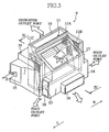
- the air-conditioning unit 9 for the vehicle is provided with a unit case 10 in which a cooling heat exchanger 11 (an evaporator) and a heat exchanger 13 (a heater core) are arranged in a blast pipe, and is structured such that a temperature of an air sucked from an introduction port 15 is regulated by adjusting an amount of a hot water circulating in the heat exchanger 13, and the regulated air is blown out from outlet ports 16, 17 and 18.
- a cooling heat exchanger 11 an evaporator
- a heat exchanger 13 a heater core
- the cooling heat exchanger 11 provided with a first member 11A, a second member 11B and a third member 11C is arranged in an upstream side of the blast pipe so as to be formed in an approximately C shape, and the heat exchanger 13 is arranged in a downstream side of the cooling heat exchanger 11 (11A, 11B and 11C) arranged in the C shape. Further, a bypass passage 19 bypassing the heating heat exchanger 13 is provided in a downstream side of the cooling heat exchanger 11. At a time of fully cooling, in order to minimize a ventilation resistance, a maximum blowout air flow amount at a time of cooling is secured by opening a bypass door 19D provided in the bypass passage 19.
- outlet ports 16, 17 and 18 are selected by selectively opening and closing mode doors 16D, 17D and 18D.
- a blast duct 20 according to the present invention is connected so as to be communicated with the outlet port 17 of the air-conditioning unit 9 mentioned above.
- the blast duct connected so as to be communicated with a defroster outlet port and a foot outlet port has the same structure as the conventional structure, a description thereof will be omitted.
- the blast duct 20 also functions as a cross member having a closed cross sectional structure connected to both side walls 2 and 2 of the vehicle in a vehicle width direction.
- an introduction port 21 and discharge ports 27 and 29 are provided in the cross member 20 arranged along the vehicle width direction and having the closed cross sectional structure, and an internal space of the cross member 20 functions as a blast pipe.
- mounting portions 25 and 25 for mounting to the vehicle body side wall 2 are provided in both ends in a longitudinal direction (both ends in the vehicle width direction) of the blast duct 20.
- the blast duct 20 holds a steering shaft (not shown) in a driver's seat side (a right side in the vehicle width direction).
- the introduction port 21 is provided in a center portion of the blast duct 20 in the vehicle width direction, and is connected to the outlet port 17 of the air-conditioning unit 9. Further, center discharge ports 27 which is comprised of a pair of discharge ports 27L and 27R are provided near a center of the introduction port 21, and left and right discharge ports 29 which is comprised of a left discharge port 29L and a right discharge port 29R are provided in a lateral direction, respectively.
- Flanges 21f, 27f and 29f are formed in peripheral edges of the introduction ports 21 and 21, and the discharge ports 27 (27L and 27R), and 29 (29L and 29R), respectively.
- the flanges 21f, 27f and 29f are provided so as to protrude toward an outer side of the blast duct 20, and reinforce the peripheral edges of the introduction ports 21, and the discharge ports 27 (27L and 27R) and 29 (29L and 29R).
- a convex rectifying portion 31 bulging toward the introduction port 21 and having an approximately V-shaped cross section is formed in an opposing wall of the flange 27f.
- the convex rectifying portion 31 is comprised of a pair of inclined walls 33 and 33 which are inclined toward outer sides L and R in the vehicle width direction.
- the wind from the introduction port 21 is separated into the discharge ports 27L and 29L in a left side L in the vehicle width direction and the discharge ports 27R and 29R in a right side R in the vehicle width direction, by the convex rectifying portion 31. Further, since the inclined walls 33 and 33 are formed in a curved shape so as to bulge to an outer wall side, the wind from the introduction port 21 is deflected toward outer sides L and R in the vehicle width direction step by step.
- a plurality of ribs 35 for reinforcing the cross member 20 are formed in a space S defined by the inclined walls 33 and 33 which are branched from a top portion 31a of the convex rectifying portion 31 and are opposed to each other.
- the ribs 35 are provided along the vehicle width direction. Further, cross ribs 36 orthogonal to the ribs 35 are formed.
- the flange 21f of the introduction port 21 is formed so as to protrude into the outlet port 17 of the air-conditioning unit 9, and has a structure which is preferable for positioning at a time of assembling the blast duct 20 and the air-conditioning unit 9.
- a cross sectional shape of the flange 21f of the introduction port 21 along the vehicle width direction is formed in a flare shape broadened toward a base end side from a leading end as shown in Figs. 5 and 7.
- the cross sectional shape of the flange 21f along the vehicle width direction is formed in an R shape bulging to an inner side of the blast pipe.
- auxiliary ducts (not shown) are connected to the blast duct 20 according to this embodiment in correspondence to the respective discharge ports 27L, 29L, 27R and 29R, and the air-conditioning wind blown out from the bent outlet port of the air-conditioning unit 9 is blown out from a predetermined position to a space within a passenger room through the auxiliary ducts.
- the opposing walls of the introduction port 21 are structured as the convex rectifying portion 31 provided with a pair of inclined walls 33 and 33 which are provided so as to protrude to the introduction port 21 and are inclined toward both sides L and R in the vehicle width direction, the wind from the introduction port 21 is smoothly separated toward the discharge ports 27L, 29L, 27R and 29R in both sides L and R in the vehicle width direction, based on a separating effect of the convex rectifying portion 31. Accordingly, a wind distributing performance of the blast duct 20 is improved.
- the peripheral edge portion of the introduction port 21 is structured as the flange 21f, it is possible to improve a rigidity near the introduction port 21. Accordingly, it is possible to complement a rigidity of an opening which tends to be fragile.
- the flange 21f of the introduction port 21 is structured as the flange 21f protruding into the outlet port 21 of the air-conditioning unit 9, the flange 21f of the blast duct 20 is engaged with the peripheral edge portion of the outlet port 17 of the air-conditioning unit 9 so as to be positioned, at a time of assembling the blast duct 20 and the air-conditioning unit 9, so that it is easy to assemble.
- the flange 21f of the introduction port 21 is formed such that the cross sectional shape along the vehicle width direction is broadened toward the base end side from the leading end.
- the structure is made such that the passage cross sectional area of the tubular flange 21f is expanded toward the downward side step by step. Accordingly, the ventilation resistance near the introduction port 21 of the blast duct 20 is further lowered, and the wind distributing performance of the blast duct 20 is improved.
- the flange 21f of the introduction port 21 is formed in the flare shape (the R shape), the wind from the introduction port 21 is more smoothly separated into both sides L and R in the vehicle width direction, in comparison with the case that the flange 21f is formed in a linear shape. Accordingly, the ventilation resistance near the introduction port 21 of the blast duct 20 becomes lower, and the wind distributing performance of the blast duct 20 is improved.
- the blast duct is provided with the discharge ports in both sides in the vehicle width direction with respect to the introduction port, and first the opposing walls of the introduction port are structured as the convex rectifying portions bulging toward the introduction port so as to separate the wind from the introduction port toward the discharge ports in both sides in the vehicle width direction. Accordingly, the wind distributing performance of the blast duct is improved.
- the reinforcing member being astride the top portion of the convex rectifying portion and connecting the walls in both sides in the vehicle width direction, it is possible to complement the rigidity of the convex rectifying portion. As a result of the structure mentioned above, it is possible to maintain the rigidity required as the cross member while improving the wind distributing performance.
- the convex rectifying portion is provided, and the rectifying portion is reinforced by the reinforcing member. Hence, it is possible to obtain the cross member having a high rigidity while improving the wind distributing performance.
Landscapes
- Engineering & Computer Science (AREA)
- Mechanical Engineering (AREA)
- Chemical & Material Sciences (AREA)
- Combustion & Propulsion (AREA)
- Transportation (AREA)
- Physics & Mathematics (AREA)
- Thermal Sciences (AREA)
- General Engineering & Computer Science (AREA)
- Air-Conditioning For Vehicles (AREA)
- Body Structure For Vehicles (AREA)
- Duct Arrangements (AREA)
Abstract
Description
- The present invention relates to a blast duct for a vehicle which is connected to an outlet port of an air-conditioning unit for a vehicle.
- With reference to Figs.1 , 2, a
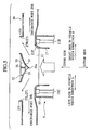
conventional blast duct 4 for a vehicle functions also as a cross member having a closed cross section structure connected betweenfront pillars 2 and 2 (side walls of a vehicle 1) (refer, for example, to Japanese Utility Model Application No. S56-155917 and Japanese Patent Application Laid-open No. H11-192972). In other words, thecross member 4 is provided with an introduction port 6 communicated with an outlet port of an air-conditioning unit 3, and adischarge port 7, and an internal space of thecross member 4 is structured as a blast pipe. Meanwhile,reference numeral 5 denotes an auxiliary duct. - According to the
blast duct 4 having the structure mentioned above, since the cross member functions also as the blast pipe, a manufacturing cost can be reduced in comparison with the case that the cross member and the blast pipe are provided as independent bodies. - DE-A-100 46 120 discloses also a conventional blast duct according to the preamble of
claim 1. - However, in the
conventional blast duct 4 for the vehicle, in order to maintain a strength of the cross member, there is room for improvement in an air distributing performance of theblast duct 4. - The present invention is made for solving the problems in the related art mentioned above, and an object of the present invention is to provide a blast duct which can maintain a strength of a cross member while improving an air distributing performance.
- In order to achieve the object mentioned above, according to the present invention, there is provided a blast duct for a vehicle which is comprised of an introduction port for introducing an air, discharge ports provided in both sides in a vehicle width direction with respect to the introduction port and discharging the air introduced from the introduction port, a convex rectifying portion formed so as to protrude to the introduction port from an inner wall of the cross member opposing to the introduction port, and distributing the air introduced from the introduction port toward the discharge port, and a first reinforcing member connecting a wall provided in a vehicle width direction of an inner wall of the cross member from a top portion of the convex rectifying portion.
-
- Fig. 1 is a schematic perspective view showing a blast duct for a vehicle which doubles as a conventional cross member;
- Fig. 2 is a schematic cross sectional view of the blast duct for the vehicle in Fig. 1;
- Fig. 3 is a perspective view of an air-conditioning unit for a vehicle to which the blast duct for the vehicle according to the present invention is connected;
- Fig. 4 is a cross sectional view along a line IV-IV in Fig. 3;
- Fig. 5 is an enlarged vertical cross sectional view along a vehicle width direction showing a state where the blast duct according to the present invention is mounted to a vent outlet port of the air-conditioning unit for the vehicle;
- Fig. 6 is a top elevational view of the blast duct;
- Fig. 7 is a cross sectional view along a line VII-VII in Fig. 6; and
- Fig. 8 is a perspective view of the blast duct.
- A preferable embodiment according to the present invention will be described below with reference to the accompanying drawings.
- An air-
conditioning unit 9 for a vehicle will be described below. The air-conditioning unit 9 for the vehicle is provided with aunit case 10 in which a cooling heat exchanger 11 (an evaporator) and a heat exchanger 13 (a heater core) are arranged in a blast pipe, and is structured such that a temperature of an air sucked from anintroduction port 15 is regulated by adjusting an amount of a hot water circulating in theheat exchanger 13, and the regulated air is blown out fromoutlet ports - In detail, the
cooling heat exchanger 11 provided with afirst member 11A, asecond member 11B and athird member 11C is arranged in an upstream side of the blast pipe so as to be formed in an approximately C shape, and theheat exchanger 13 is arranged in a downstream side of the cooling heat exchanger 11 (11A, 11B and 11C) arranged in the C shape. Further, abypass passage 19 bypassing theheating heat exchanger 13 is provided in a downstream side of thecooling heat exchanger 11. At a time of fully cooling, in order to minimize a ventilation resistance, a maximum blowout air flow amount at a time of cooling is secured by opening abypass door 19D provided in thebypass passage 19. - In this case, the
outlet ports mode doors - A
blast duct 20 according to the present invention is connected so as to be communicated with theoutlet port 17 of the air-conditioning unit 9 mentioned above. In this case, since the blast duct connected so as to be communicated with a defroster outlet port and a foot outlet port has the same structure as the conventional structure, a description thereof will be omitted. - As shown in Figs.5 to 7, the
blast duct 20 also functions as a cross member having a closed cross sectional structure connected to bothside walls introduction port 21 anddischarge ports cross member 20 arranged along the vehicle width direction and having the closed cross sectional structure, and an internal space of thecross member 20 functions as a blast pipe. - With reference to Fig. 6, mounting
portions body side wall 2 are provided in both ends in a longitudinal direction (both ends in the vehicle width direction) of theblast duct 20. According to the present embodiment, theblast duct 20 holds a steering shaft (not shown) in a driver's seat side (a right side in the vehicle width direction). - The
introduction port 21 is provided in a center portion of theblast duct 20 in the vehicle width direction, and is connected to theoutlet port 17 of the air-conditioning unit 9. Further,center discharge ports 27 which is comprised of a pair ofdischarge ports introduction port 21, and left andright discharge ports 29 which is comprised of aleft discharge port 29L and aright discharge port 29R are provided in a lateral direction, respectively. -
Flanges introduction ports flanges blast duct 20, and reinforce the peripheral edges of theintroduction ports 21, and the discharge ports 27 (27L and 27R) and 29 (29L and 29R). - A convex rectifying
portion 31 bulging toward theintroduction port 21 and having an approximately V-shaped cross section is formed in an opposing wall of theflange 27f. The convex rectifyingportion 31 is comprised of a pair ofinclined walls - The wind from the
introduction port 21 is separated into thedischarge ports discharge ports portion 31. Further, since theinclined walls introduction port 21 is deflected toward outer sides L and R in the vehicle width direction step by step. - A plurality of
ribs 35 for reinforcing thecross member 20 are formed in a space S defined by theinclined walls top portion 31a of the convex rectifyingportion 31 and are opposed to each other. Theribs 35 are provided along the vehicle width direction. Further,cross ribs 36 orthogonal to theribs 35 are formed. - The
flange 21f of theintroduction port 21 is formed so as to protrude into theoutlet port 17 of the air-conditioning unit 9, and has a structure which is preferable for positioning at a time of assembling theblast duct 20 and the air-conditioning unit 9. A cross sectional shape of theflange 21f of theintroduction port 21 along the vehicle width direction is formed in a flare shape broadened toward a base end side from a leading end as shown in Figs. 5 and 7. In other words, the cross sectional shape of theflange 21f along the vehicle width direction is formed in an R shape bulging to an inner side of the blast pipe. - In this case, auxiliary ducts (not shown) are connected to the
blast duct 20 according to this embodiment in correspondence to therespective discharge ports conditioning unit 9 is blown out from a predetermined position to a space within a passenger room through the auxiliary ducts. - According to the
blast duct 20 of the embodiment, the following effects can be achieved. - First, i) since the opposing walls of the
introduction port 21 are structured as the convex rectifyingportion 31 provided with a pair ofinclined walls introduction port 21 and are inclined toward both sides L and R in the vehicle width direction, the wind from theintroduction port 21 is smoothly separated toward thedischarge ports portion 31. Accordingly, a wind distributing performance of theblast duct 20 is improved. Further, ii) since there is provided with the rib 35 (the reinforcing member) being astride thetop portion 31a of the convex rectifyingportion 31 and connecting thewalls portion 31. As a result, it is possible to obtain a desired rigidity required as the cross member while improving the wind distributing performance. - Secondly, since the peripheral edge portion of the
introduction port 21 is structured as theflange 21f, it is possible to improve a rigidity near theintroduction port 21. Accordingly, it is possible to complement a rigidity of an opening which tends to be fragile. - Thirdly, since the
flange 21f of theintroduction port 21 is structured as theflange 21f protruding into theoutlet port 21 of the air-conditioning unit 9, theflange 21f of theblast duct 20 is engaged with the peripheral edge portion of theoutlet port 17 of the air-conditioning unit 9 so as to be positioned, at a time of assembling theblast duct 20 and the air-conditioning unit 9, so that it is easy to assemble. - Fourthly, the
flange 21f of theintroduction port 21 is formed such that the cross sectional shape along the vehicle width direction is broadened toward the base end side from the leading end. In other words, the structure is made such that the passage cross sectional area of thetubular flange 21f is expanded toward the downward side step by step. Accordingly, the ventilation resistance near theintroduction port 21 of theblast duct 20 is further lowered, and the wind distributing performance of theblast duct 20 is improved. - Fifthly, since the
flange 21f of theintroduction port 21 is formed in the flare shape (the R shape), the wind from theintroduction port 21 is more smoothly separated into both sides L and R in the vehicle width direction, in comparison with the case that theflange 21f is formed in a linear shape. Accordingly, the ventilation resistance near theintroduction port 21 of theblast duct 20 becomes lower, and the wind distributing performance of theblast duct 20 is improved. - Sixthly, since a pair of opposing
inclined walls convex rectifying portion 31 are formed in the curved shape (the R shape) so as to bulge toward the outer side of the blast passage, the wind from theintroduction port 21 is more smoothly separated into both sides L and R in the vehicle width direction, in comparison with the case that the inclined wall is formed in the linear shape. Accordingly, the ventilation resistance near theintroduction port 21 of theblast duct 20 is further lowered, and the wind distributing performance of theblast duct 20 is improved. - As is understood from the description mentioned above, according to the present invention, the blast duct is provided with the discharge ports in both sides in the vehicle width direction with respect to the introduction port, and first the opposing walls of the introduction port are structured as the convex rectifying portions bulging toward the introduction port so as to separate the wind from the introduction port toward the discharge ports in both sides in the vehicle width direction. Accordingly, the wind distributing performance of the blast duct is improved.
- Furthermore, since there is provided the reinforcing member being astride the top portion of the convex rectifying portion and connecting the walls in both sides in the vehicle width direction, it is possible to complement the rigidity of the convex rectifying portion. As a result of the structure mentioned above, it is possible to maintain the rigidity required as the cross member while improving the wind distributing performance.
- According to the present invention, since the convex rectifying portion is provided, and the rectifying portion is reinforced by the reinforcing member. Hence, it is possible to obtain the cross member having a high rigidity while improving the wind distributing performance.
Claims (7)
- A blast duct (20) for a vehicle provided in a cross member connecting both side walls in a vehicle width direction of a vehicle body comprising:an introduction port (21) for introducing an air;discharge ports (27, 29) provided in both sides in a vehicle width direction with respect to the introduction port (21) and discharging the air introduced from the introduction port;the blast duct (20) being characterised in that it furthermore comprises:a convex rectifying portion (31) formed so as to protrude to the introduction port (21) from an inner wall of the cross member opposing to the introduction port, and distributing the air introduced from the introduction port toward the discharge port (27, 29); anda first reinforcing member (35) connecting a wall provided in a vehicle width direction of an inner wall of the cross member from a top portion of the convex rectifying portion.
- A blast duct for a vehicle according to claim 1, wherein a flange (21f) is provided in a peripheral edge portion of the introduction port.
- A blast duct for a vehicle according to claim 2, wherein the flange of (21f) the introduction port (21) protrudes to an inner side of the outlet port (27, 29) in such a manner as to be engaged with an outlet port of an air-conditioning unit.
- A blast duct for a vehicle according to claim 3, wherein the flange (21f) of the introduction port (21) is formed so as to be broadened from an opening of the introduction port to a base end side in a cross sectional shape along the vehicle width direction.
- A blast duct for a vehicle according to claim 4, wherein the flange (21f) of the introduction port (21) is formed in a flare shape which is broadened from an opening of the introduction port (21) to a base end side in a cross sectional shape along the vehicle width direction.
- A blast duct for a vehicle according to any one of claims 1 to 5, wherein the convex rectifying portion (31) is comprised of a pair of opposing inclined walls (33), and the inclined walls (33) are formed in a curved shape so as to bulge toward an outer side of the blast pipe for introducing the air introduced from the introduction port in a longitudinal direction of the blast duct for the vehicle.
- A blast duct for a vehicle according to claim 1, wherein a second reinforcing member (36) is provided at a position orthogonal to the first reinforcing member (35).
Applications Claiming Priority (2)
| Application Number | Priority Date | Filing Date | Title |
|---|---|---|---|
| JP2003073815A JP2004345363A (en) | 2003-03-18 | 2003-03-18 | Air duct for vehicle |
| PCT/JP2004/003434 WO2004082970A1 (en) | 2003-03-18 | 2004-03-15 | Blast duct for vehicle |
Publications (2)
| Publication Number | Publication Date |
|---|---|
| EP1610968A1 EP1610968A1 (en) | 2006-01-04 |
| EP1610968B1 true EP1610968B1 (en) | 2006-12-13 |
Family
ID=33027799
Family Applications (1)
| Application Number | Title | Priority Date | Filing Date |
|---|---|---|---|
| EP04720745A Expired - Lifetime EP1610968B1 (en) | 2003-03-18 | 2004-03-15 | Blast duct for vehicle |
Country Status (7)
| Country | Link |
|---|---|
| US (1) | US20060199494A1 (en) |
| EP (1) | EP1610968B1 (en) |
| JP (1) | JP2004345363A (en) |
| KR (1) | KR100729312B1 (en) |
| CN (1) | CN100389975C (en) |
| DE (1) | DE602004003687T2 (en) |
| WO (1) | WO2004082970A1 (en) |
Families Citing this family (8)
| Publication number | Priority date | Publication date | Assignee | Title |
|---|---|---|---|---|
| EP1685989A3 (en) * | 2005-01-26 | 2007-05-02 | Calsonic Kansei Corporation | Airflow distribution structure of vehicular air conditioning system |
| DE102010042299A1 (en) | 2010-10-12 | 2012-04-12 | Behr Gmbh & Co. Kg | Air conditioning apparatus mounted in motor car, has mixture space that is formed partly from cavity of two-piece cross beam of motor vehicle |
| JP6146661B2 (en) * | 2013-05-17 | 2017-06-14 | スズキ株式会社 | Steering support member structure |
| CN105180394A (en) * | 2015-08-11 | 2015-12-23 | 华晨汽车集团控股有限公司 | Vehicle-mounted air conditioner blowpipe structure |
| JP6894355B2 (en) * | 2017-11-27 | 2021-06-30 | トヨタ自動車株式会社 | Resin radiator support duct |
| JP6958388B2 (en) * | 2018-01-27 | 2021-11-02 | マツダ株式会社 | Vehicle air conditioner |
| JP6958389B2 (en) * | 2018-01-27 | 2021-11-02 | マツダ株式会社 | Vehicle air conditioner |
| JP7344763B2 (en) * | 2019-11-06 | 2023-09-14 | 株式会社日立製作所 | mobile air purifier |
Family Cites Families (38)
| Publication number | Priority date | Publication date | Assignee | Title |
|---|---|---|---|---|
| US2021408A (en) * | 1931-10-05 | 1935-11-19 | Feinberg Archie | Ventilating system |
| US3521653A (en) * | 1967-12-13 | 1970-07-28 | Sperry Rand Corp | Power transmission |
| DE3323176C2 (en) * | 1983-06-28 | 1989-04-27 | Adam Opel AG, 6090 Rüsselsheim | Heating and ventilation device for the passenger compartment of motor vehicles |
| US4773310A (en) * | 1986-12-01 | 1988-09-27 | Howard Corwin | Fan ventilator having multiple modes of operation |
| JP2661344B2 (en) * | 1990-08-09 | 1997-10-08 | 日産自動車株式会社 | Defroster structure of automotive air conditioner |
| US5129394A (en) * | 1991-01-07 | 1992-07-14 | Medtronic, Inc. | Method and apparatus for controlling heart rate in proportion to left ventricular pressure |
| EP0545320B1 (en) * | 1991-11-29 | 1997-01-29 | Nippondenso Co., Ltd. | Air passage changeover device |
| FR2710296B1 (en) * | 1993-09-21 | 1995-10-27 | Smh Management Services Ag | Air conditioning device for motor vehicles. |
| US5509888A (en) * | 1994-07-26 | 1996-04-23 | Conceptek Corporation | Controller valve device and method |
| EP0705725B1 (en) * | 1994-10-07 | 1999-03-24 | Denso Corporation | Air conditioning apparatus with film door |
| US6010470A (en) * | 1995-07-10 | 2000-01-04 | The United States Of America As Represented By The Secretary Of The Air Force | Automated retrograde inflation cardiopulmonary resuscitation trousers |
| JP3692572B2 (en) * | 1995-10-12 | 2005-09-07 | 株式会社デンソー | Air conditioner |
| JP3493093B2 (en) * | 1996-02-16 | 2004-02-03 | 本田技研工業株式会社 | Damper mechanism for vehicle air conditioner |
| US6141590A (en) * | 1997-09-25 | 2000-10-31 | Medtronic, Inc. | System and method for respiration-modulated pacing |
| US6422990B1 (en) * | 1997-11-26 | 2002-07-23 | Vascor, Inc. | Blood pump flow rate control method and apparatus utilizing multiple sensors |
| JP4048587B2 (en) * | 1998-02-19 | 2008-02-20 | 株式会社デンソー | Air conditioner for vehicles |
| JP4013315B2 (en) * | 1998-03-11 | 2007-11-28 | 株式会社デンソー | Air conditioner for vehicles |
| US5964658A (en) * | 1998-03-31 | 1999-10-12 | Denso Corporation | Air passage opening/closing system for air conditioning apparatus |
| US6086527A (en) * | 1998-04-02 | 2000-07-11 | Scimed Life Systems, Inc. | System for treating congestive heart failure |
| US5885152A (en) * | 1998-04-20 | 1999-03-23 | General Motors Corporation | Automotive ventilation housing with self supporting film valve having a convex semi-cylindrical shape |
| US6045444A (en) * | 1998-08-28 | 2000-04-04 | General Motors Corporation | Compact automotive air conditioning module |
| US6296562B1 (en) * | 1998-09-08 | 2001-10-02 | Denso Corporation | Air passage switching device and air conditioning apparatus having the same |
| US6231551B1 (en) * | 1999-03-01 | 2001-05-15 | Coaxia, Inc. | Partial aortic occlusion devices and methods for cerebral perfusion augmentation |
| DE19938453A1 (en) * | 1999-08-13 | 2001-02-15 | Bayerische Motoren Werke Ag | Air guidance system for a motor vehicle |
| DE29916466U1 (en) * | 1999-09-18 | 1999-12-09 | Benteler Ag, 33104 Paderborn | Instrument holder |
| US6275727B1 (en) * | 1999-11-04 | 2001-08-14 | Cardiac Pacemakers, Inc. | Implantable cardiac rhythm management device for assessing status of CHF patients |
| JP4396013B2 (en) * | 1999-11-11 | 2010-01-13 | 株式会社デンソー | Air passage opening and closing device |
| JP2001213139A (en) * | 1999-11-26 | 2001-08-07 | Inoac Corp | Air guide duct for vehicles |
| US6926068B2 (en) * | 2000-01-13 | 2005-08-09 | Denso Corporation | Air passage switching device and vehicle air conditioner |
| FR2806366B1 (en) * | 2000-03-20 | 2002-07-26 | Valeo Climatisation | STRUCTURING TRANSVERSE BEAM AND METHOD OF MAKING |
| DE10014606A1 (en) * | 2000-03-24 | 2001-10-11 | Behr Gmbh & Co | Cross member in hybrid construction |
| US6507756B1 (en) * | 2000-04-03 | 2003-01-14 | Medtronic, Inc. | Dual chamber pacing system having time-adaptive AV delay |
| US6473647B1 (en) * | 2000-10-18 | 2002-10-29 | Pacesetter, Inc. | Implantable cardiac stimulation device for and method of monitoring progression or regression of heart disease by monitoring evoked response features |
| ITTO20010223A1 (en) * | 2001-03-12 | 2002-09-12 | Fiat Ricerche | AIR DISTRIBUTION SYSTEM. |
| US8091556B2 (en) * | 2001-04-20 | 2012-01-10 | V-Wave Ltd. | Methods and apparatus for reducing localized circulatory system pressure |
| JP3605577B2 (en) * | 2001-05-15 | 2004-12-22 | 本田技研工業株式会社 | Air outlet for air conditioning |
| JP4093031B2 (en) * | 2002-11-28 | 2008-05-28 | 株式会社デンソー | Fluid path control device |
| US6932691B1 (en) * | 2004-05-28 | 2005-08-23 | Macauto Industrial Co., Ltd. | Film valve assembly for a heating, ventilation and air conditioning system |
-
2003
- 2003-03-18 JP JP2003073815A patent/JP2004345363A/en active Pending
-
2004
- 2004-03-15 US US10/549,197 patent/US20060199494A1/en not_active Abandoned
- 2004-03-15 EP EP04720745A patent/EP1610968B1/en not_active Expired - Lifetime
- 2004-03-15 KR KR1020057017361A patent/KR100729312B1/en not_active Expired - Fee Related
- 2004-03-15 DE DE602004003687T patent/DE602004003687T2/en not_active Expired - Fee Related
- 2004-03-15 CN CNB2004800071938A patent/CN100389975C/en not_active Expired - Fee Related
- 2004-03-15 WO PCT/JP2004/003434 patent/WO2004082970A1/en not_active Ceased
Also Published As
| Publication number | Publication date |
|---|---|
| KR100729312B1 (en) | 2007-06-19 |
| JP2004345363A (en) | 2004-12-09 |
| US20060199494A1 (en) | 2006-09-07 |
| CN1761587A (en) | 2006-04-19 |
| EP1610968A1 (en) | 2006-01-04 |
| WO2004082970A1 (en) | 2004-09-30 |
| DE602004003687D1 (en) | 2007-01-25 |
| DE602004003687T2 (en) | 2007-04-12 |
| CN100389975C (en) | 2008-05-28 |
| KR20050109587A (en) | 2005-11-21 |
Similar Documents
| Publication | Publication Date | Title |
|---|---|---|
| EP1424228B1 (en) | Air conditioner for vehicle | |
| EP1270294B1 (en) | Automotive air conditioner | |
| CN112026935B (en) | Front-end structure | |
| US20060199494A1 (en) | Blast duct for vehicle | |
| CN112026934B (en) | Front-end structure | |
| WO2006080631A1 (en) | Console air conditioner for vehicle | |
| EP2944487B1 (en) | Light weight hvac module | |
| JP2007022484A (en) | Temperature adjustment unit for air-conditioning unit | |
| US20070158047A1 (en) | Air conditioner for vehicle | |
| JP4431955B2 (en) | Air conditioning baffle plate and air conditioning unit temperature control unit using the same | |
| US20070128997A1 (en) | Vehicle air duct structure | |
| KR101737911B1 (en) | Air conditioner for vehicle | |
| JP4209695B2 (en) | VEHICLE AIR CONDITIONING UNIT AND VEHICLE AIR CONDITIONER | |
| JP2003136942A (en) | Vehicle mounting structure of air conditioner and vehicle mounting method | |
| US7036576B2 (en) | Automotive air conditioner | |
| JP6958388B2 (en) | Vehicle air conditioner | |
| JP2003200726A (en) | Vehicle air conditioner | |
| KR100209038B1 (en) | Heater/cooler unit of automotive air-conditioning system | |
| JP3639234B2 (en) | Air conditioner for vehicles | |
| JP2008126802A (en) | Air conditioner for vehicles | |
| JP2003072360A (en) | Vehicle air conditioner | |
| JP5324939B2 (en) | Air conditioner for vehicles | |
| JP2003165323A (en) | Automotive steering member | |
| JP2006205828A (en) | Air distribution structure of air conditioner for vehicle |
Legal Events
| Date | Code | Title | Description |
|---|---|---|---|
| PUAI | Public reference made under article 153(3) epc to a published international application that has entered the european phase |
Free format text: ORIGINAL CODE: 0009012 |
|
| 17P | Request for examination filed |
Effective date: 20051017 |
|
| AK | Designated contracting states |
Kind code of ref document: A1 Designated state(s): AT BE BG CH CY CZ DE DK EE ES FI FR GB GR HU IE IT LI LU MC NL PL PT RO SE SI SK TR |
|
| AX | Request for extension of the european patent |
Extension state: AL LT LV MK |
|
| GRAP | Despatch of communication of intention to grant a patent |
Free format text: ORIGINAL CODE: EPIDOSNIGR1 |
|
| DAX | Request for extension of the european patent (deleted) | ||
| RBV | Designated contracting states (corrected) |
Designated state(s): DE FR GB |
|
| GRAS | Grant fee paid |
Free format text: ORIGINAL CODE: EPIDOSNIGR3 |
|
| GRAA | (expected) grant |
Free format text: ORIGINAL CODE: 0009210 |
|
| AK | Designated contracting states |
Kind code of ref document: B1 Designated state(s): DE FR GB |
|
| REG | Reference to a national code |
Ref country code: GB Ref legal event code: FG4D |
|
| REF | Corresponds to: |
Ref document number: 602004003687 Country of ref document: DE Date of ref document: 20070125 Kind code of ref document: P |
|
| ET | Fr: translation filed | ||
| PLBE | No opposition filed within time limit |
Free format text: ORIGINAL CODE: 0009261 |
|
| STAA | Information on the status of an ep patent application or granted ep patent |
Free format text: STATUS: NO OPPOSITION FILED WITHIN TIME LIMIT |
|
| 26N | No opposition filed |
Effective date: 20070914 |
|
| PGFP | Annual fee paid to national office [announced via postgrant information from national office to epo] |
Ref country code: GB Payment date: 20090311 Year of fee payment: 6 |
|
| PGFP | Annual fee paid to national office [announced via postgrant information from national office to epo] |
Ref country code: DE Payment date: 20090313 Year of fee payment: 6 |
|
| REG | Reference to a national code |
Ref country code: GB Ref legal event code: 746 Effective date: 20090924 |
|
| PGFP | Annual fee paid to national office [announced via postgrant information from national office to epo] |
Ref country code: FR Payment date: 20090316 Year of fee payment: 6 |
|
| GBPC | Gb: european patent ceased through non-payment of renewal fee |
Effective date: 20100315 |
|
| REG | Reference to a national code |
Ref country code: FR Ref legal event code: ST Effective date: 20101130 |
|
| PG25 | Lapsed in a contracting state [announced via postgrant information from national office to epo] |
Ref country code: FR Free format text: LAPSE BECAUSE OF NON-PAYMENT OF DUE FEES Effective date: 20100331 |
|
| PG25 | Lapsed in a contracting state [announced via postgrant information from national office to epo] |
Ref country code: DE Free format text: LAPSE BECAUSE OF NON-PAYMENT OF DUE FEES Effective date: 20101001 |
|
| PG25 | Lapsed in a contracting state [announced via postgrant information from national office to epo] |
Ref country code: GB Free format text: LAPSE BECAUSE OF NON-PAYMENT OF DUE FEES Effective date: 20100315 |