EP1610586B1 - Anordnung zum Freihalten eines Lautsprechers für ein Kommunikationsgerät - Google Patents
Anordnung zum Freihalten eines Lautsprechers für ein Kommunikationsgerät Download PDFInfo
- Publication number
- EP1610586B1 EP1610586B1 EP04102421A EP04102421A EP1610586B1 EP 1610586 B1 EP1610586 B1 EP 1610586B1 EP 04102421 A EP04102421 A EP 04102421A EP 04102421 A EP04102421 A EP 04102421A EP 1610586 B1 EP1610586 B1 EP 1610586B1
- Authority
- EP
- European Patent Office
- Prior art keywords
- speaker
- casing
- cover
- enclosure system
- speaker enclosure
- Prior art date
- Legal status (The legal status is an assumption and is not a legal conclusion. Google has not performed a legal analysis and makes no representation as to the accuracy of the status listed.)
- Expired - Lifetime
Links
Images


Classifications
-
- H—ELECTRICITY
- H04—ELECTRIC COMMUNICATION TECHNIQUE
- H04R—LOUDSPEAKERS, MICROPHONES, GRAMOPHONE PICK-UPS OR LIKE ACOUSTIC ELECTROMECHANICAL TRANSDUCERS; ELECTRIC HEARING AIDS; PUBLIC ADDRESS SYSTEMS
- H04R1/00—Details of transducers, loudspeakers or microphones
- H04R1/02—Casings; Cabinets ; Supports therefor; Mountings therein
- H04R1/026—Supports for loudspeaker casings
-
- H—ELECTRICITY
- H04—ELECTRIC COMMUNICATION TECHNIQUE
- H04M—TELEPHONIC COMMUNICATION
- H04M1/00—Substation equipment, e.g. for use by subscribers
- H04M1/02—Constructional features of telephone sets
- H04M1/03—Constructional features of telephone transmitters or receivers, e.g. telephone hand-sets
-
- H—ELECTRICITY
- H04—ELECTRIC COMMUNICATION TECHNIQUE
- H04R—LOUDSPEAKERS, MICROPHONES, GRAMOPHONE PICK-UPS OR LIKE ACOUSTIC ELECTROMECHANICAL TRANSDUCERS; ELECTRIC HEARING AIDS; PUBLIC ADDRESS SYSTEMS
- H04R2499/00—Aspects covered by H04R or H04S not otherwise provided for in their subgroups
- H04R2499/10—General applications
- H04R2499/11—Transducers incorporated or for use in hand-held devices, e.g. mobile phones, PDA's, camera's
Definitions
- the invention relates to a system for enhancing audibility of signals generated by a communication device, such as a cellular phone.
- a typical voice communication device such as a cellular phone, has a receiver (speaker) located at a top portion of the device and a transducer (microphone) located at a bottom portion.
- a user of the device generally holds and orients it by a side of his head such that the speaker is near his ear and the microphone is near his mouth.
- the device may have hands-free functionality.
- One implementation of the hands-free functionality is to have a speaker located on the back of the device. However, when that device is placed on a hard flat surface like a desktop, the surface blocks the speaker and the sound from the speaker is muted and muffled.
- a smaller device such as a tiny cellular phone, has a rounded back, such that the back does not sit flat against the surface, thereby preventing the speaker from being fully blocked when lying on a flat surface.
- having a rounded back allows the device to pitch on the surface.
- EP-A-1301013 discloses a mobile communication device having a distance keeping means projecting from a back surface of the device.
- a speaker means for hands-free operation is located internally of the device with its acoustic opening located towards the centre of the back surface.
- the distance keeping means is positioned above the speaker opening and a top of the device such that, when the device is placed on a flat surface with its back surface facing said flat surface, the distance keeping means keeps the acoustic opening of the speaker means spaced above the flat surface.
- the invention provides a speaker enclosure system for a communication device comprising: a casing for said communication device, said casing having a side and a casing opening in a top portion of said side; a speaker mounted inside said casing and in communication with said casing opening; a cover shaped to cover said casing opening, said cover having a speaker grill having an opening therein providing an air channel for said speaker; and a first structure and a second structure each located on a surface of said cover and protruding outwardly from said surface, said first and second structures being located on opposing sides of said speaker grill and extending towards a bottom portion of said casing such that said first and second structures extend below said speaker grill, whereby said communication device is adapted to be placed on a flat surface with said side of said casing facing said flat surface such that said first and second structures cause said side of said casing to be canted from said flat surface to expose said speaker grill to ambient air.
- the surface is canted from the flat surface by interaction of the first and second structures and a second region on the surface.
- the surface may be on a back side of the enclosure.
- the speaker grill may be detachable from said cover.
- the cover may have a recessed opening underneath said speaker grill.
- the cover may comprises a center portion, a left flange extending from a left side of said center portion and a right flange extending from a right side of said center portion; and said first and second structures may comprise a first elevated feature located in said left flange and said center portion and a second elevated feature located in said right flange and said center portion.
- the first elevated feature may comprise a first rail extending along said left flange; and said second elevated feature may also comprise a first rail extending along said right flange.
- the first elevated feature may further comprise a second rail extending along said center portion, said second rail connected to said first rail; and said second elevated feature may further comprise a second rail extending along said center portion, said second rail connected to said first rail.
- the heights of said first rails may taper as they extend outwardly to an end of their associated flanges; and, for each of said two elevated features, the heights of the second rails may taper as they extend outwardly to an end of said center portion.
- each of the first rails for each of said two elevated features may be located along an end of said associated flanges; and each of said second rails for each of said two elevated features may be located along opposing ends of said center portion.
- the casing may further comprises a recessed flange located beside the casing opening and a fastener hole for receiving a fastener; and the cover is further shaped to fit over said recessed flange.
- the cover may further comprise at least one bottom flange extending from a bottom side of said center portion.
- the cover may further comprise at least one alignment flange along an edge of said cover; said casing further comprises at least one opening located about said casing opening; and said at least one alignment flange is mateable with said at least one opening to secure said cover to said casing.
- Figure 1 is a top perspective diagram of a communication device associated with an embodiment of the invention
- Figure 2 is a rear view of the communication device of Fig. 1 ;
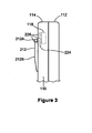
- Figure 3 is a side view of part of the communication device of Fig. 1 ;
- Figure 4 is a rear perspective view of part of a bottom cover of the device of Fig. 1 ;
- Figure 5 is a rear perspective view of part of a back casing of the device of Fig. 1 ;
- Figure 6 is a rear perspective view of part of the back casing and a back cover of the communication device as shown in Figs. 1 , 4 and 5 ;
- Figure 7 is a rear view of a second embodiment
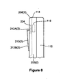
- Figure 8 is a side view of part of the second embodiment
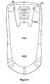
- Figure 9 is a rear view of a communication device.
- Figure 10 is a side view of part of the device of Fig 9 .
- communication device 100 provides voice communications with other devices, allowing its user to hear audio signals (e.g. voices) transmitted from another device (e.g. a cellular phone).
- Device 100 may be a telephone, a cordless telephone, a cellular telephone, a voice-enabled personal digital assistant (PDA) or any other voice communication device. Communications may be provided via wireless systems, wired systems or a combination of both systems.
- PDA personal digital assistant
- device 100 has a keypad 102, display 104, microphone 106 and transducer 108, i.e. speaker 108.
- On the back of device 100 is an additional speaker (not shown).
- casing 110 provides an enclosure for its internal circuits and mechanical structures.
- Casing 110 includes top cover 112 and bottom cover 114 and is made from a plastic injection moulded process. Top cover 112 and bottom cover 114 meet to define an exterior perimeter of device 100 along side 116. Casing 110 may be formed from any suitable material, such as plastic and metal, or any combination of both. General internal circuits and operations of device 100 are well known in the art and are not provided here.
- Device 100 provides voice communications for a user with a familiar interface. To initiate a call, the user activates device 100, enters a telephone number to be called on keypad 102 and initiates the call. After the call is connected, the user places device 100 about his mouth and one of his ears, such that microphone 106 is near his mouth and speaker 108 is near his ear. User speaks towards microphone 106 and listens for audio signals from the called party through speaker 108. Device 100 may have an external control to adjust the volume control for audio signals generated by speaker 108.
- device 100 it is possible to use device 100 in a hands-free mode, by increasing the volume of sound for speaker 108. As such, the user can operate device 100 without requiring him to place device 100 and speaker 108 near his ear. Now, device 100 may be held by user in front of him, such that he can see the front of device 100 while still being able to hear received audio signals. When device 100 is held in such a position, the user may be able to simultaneously hear the received audio signals, operate keypad 102 to provide commands to device 100 and see information on display 104.
- Device 100 provides an alternative hands-free mode of operation.
- speaker 118 is also provided on device 100.
- speaker 118 is a larger transducer than speaker 108 and is generally able to produce audio signals through a wider frequency range and at higher volume levels than speaker 108.
- other speakers may be used.
- speaker 118 is located on the back of device 100.
- speaker 118 may be placed on the front, top, bottom or a side of the device.
- device 100 activates speaker 118 and provides an audio signal to speaker 118 to reproduce the received audio signals at a volume level which is sufficient to be heard by the user when device 100 is located in front of him.
- Bottom cover 114 has an oblong-shaped surface 202 and side 204.
- Surface 202 is almost flat, having a slight convex shape to it.
- Side 204 defines a lower portion of exterior side 116 of device 100.
- Side 204 is rounded to provide a softer contour to bottom cover 114.
- the back may be flat.
- Speaker 118 is located in the top portion of bottom cover 114.
- bottom cover 114 is made in two pieces: back casing 206 and back cover 208.
- Back casing 206 provides a lower portion of bottom cover 114 and side 204.
- back casing 206 has opening 209, wherein speaker 118 is located inside device 100.
- back casing 206 has flanges 211 that extend from the sides of back casing 206 toward opening 209.
- Flanges 211 are located at the sides of the opening and protrude from the internal upper surface of back casing 206.
- Flanges 211 contain screw holes 213 for locating securing screws (or any other equivalent fastener) which lock back casing 206 to internal structural components of device 100 (not shown).
- Back cover 208 has base portion 210 and rails 212.
- Base portion 210 is shaped to be almost flat and fits snugly over the opening to cover it fully and to abut against an edge defined by the boundary of the opening and back casing 206.
- Base portion 210 has a thickness which allows it to cover the opening and flanges 211 and provide the appearance of a continual surface (but for the boundary defining the perimeter of the opening) for bottom cover 114.
- Base portion 210 has a center portion 214, side flanges 216 and bottom flanges 218. Extending below bottom flanges 218 are alignment flanges 220 which are mateable into openings 222 of back casing 206 to provide a friction fit between cover 208 and casing 206.
- grill section 224 is located around its middle and provides an opening as a set of lateral slots 226.
- grill section 224 is slightly recessed below the surface of base portion 210.
- lateral slots are located near speaker 118, allowing any sound generated therefrom to pass through them into the ambient environment of device 100.
- grill section 224 may not be recessed.
- grill section 224 is integrated into base portion 210.
- grill section 224 is removeable from base portion 210.
- Back cover 208 may be injected moulded plastic. The durability of the material of back cover 208 can depend on its intended operating environment.
- Each rail 212 located in a symmetric pattern about edges of base portion 210.
- Each rail 212 comprises two sections: rail 212A and rail 212B.
- Each rail 212A is located along the lower edge of a side flange 216.
- Each rail 212B is connected to its corresponding rail 212A and runs from the top of the exterior side of both base portion 210 and its neighbouring bottom flange 218.
- Rails 212 are relatively thin volumes having a rectanguloid (i.e., generally rectangular) cross-section.
- rails 212 extend approximately 1 mm downward from base portion 210. However, the height of a rail 212 may change through its length.
- Both rails 212A and 212B are shown as having a higher height near the center of base portion 210 and then a tapering height as they progress outwardly therefrom. It will be appreciated that the height of rails in other embodiments can be set to almost any value, if aesthetics are disregarded. As Fig. 2 shows, rails 212 are located near grill section 224. Rails 212 preferably are the only significant outwardly extending feature present on back 214. This provides a clean appearance to back 214. Rails 212 may be made from a pliable form of plastic or rubber, thereby providing some shock absorption and resistance to movement when casing 206 is rested on a hard surface. In other embodiments any shaped extension, feature or protrusion which extends from the case could be suitable.
- each of rails 212 defines a first region of contact with the flat surface and the line of contact defines a second region of contact.
- three points of contact provide a stable, non-tipping platform.
- the plane of bottom cover 114 is not coplanar with the plane of the surface.
- grill section 224 is canted upward and away from the surface.
- speaker 118 has clearance from the surface and an air channel to the ambient environment is created. As such, audio signals can be emitted through the air channel created by the cant between bottom cover 114 and the surface.
- the points of contact may only be the rails, provided they have sufficient length and height to support device 100.
- Figs. 7 and 8 show another embodiment, wherein back casing 206(2) and base portion 210(2) are dimensionally similar to back casing 206 and base portion 210.
- Rails 212(2) are located in the same locations on base portion 210(2).
- rails 212A(2) that are located along the sides of central portion 214(2) and bottom flanges 218(2) have a differently tapered height, compared to those in base portion 210, decreasing in height from the of rails 212A(2) in side flanges 216(2), as rails 212A(2) progress downward along bottom cover 114(2).
- This taper provides more points of contact when device 100(2) is placed on a surface and minimizes the visual prominence of rails 212A(2) on back 214(2).
- Figs. 9 and 10 show an embodiment of a communication device which is useful for understanding the invention but which does not fall within the scope of the appended claims, wherein back casing 206(3) and base portion 210(3) are dimensionally similar to back casing 206 and base portion 210.
- Two nubs 228 extend outwardly from an upper region of base portion 210(3) and are located in a symmetrical pattern in view of the grill and the bottom of back casing 206(3). In other embodiments 1, 2, 3 or more nubs may be provided at different locations on back 214. Nubs 228 provide a similar prop to cant back 214B from a surface.
- covers 208, 208(2) and 208(3) are dimensionally identical regarding the interface to back casing 206. As such, the covers can be interchanged, as needed.
- an aspect of the embodiment provides a structural means for a case of a communication device to be canted from a surface thereby allowing a speaker located in the case to be exposed to ambient air.
- Ambient air accesses the speaker through a speaker grill in the case, where the grill has a series of openings therein.
- rails on the back may be placed towards an opposite end of the location of the larger speaker.
- the rails or nub may be placed on the back casing.
- the structural means may be any shaped structural element(s) protruding from the case to appropriately cant the case to expose it to ambient air.
- other structural elements may be disks, domes, bumps, blocks or the like.
- the back casing may be a single piece with cover integrated into the back casing as one piece.
Landscapes
- Engineering & Computer Science (AREA)
- Signal Processing (AREA)
- Physics & Mathematics (AREA)
- Acoustics & Sound (AREA)
- Telephone Set Structure (AREA)
- Structure Of Receivers (AREA)
- Casings For Electric Apparatus (AREA)
- Details Of Audible-Bandwidth Transducers (AREA)
Claims (17)
- Lautsprecherumschließungssystem für ein Kommunikationsgerät (100), wobei das Umschließungssystem umfasst:ein Gehäuse (206) für das Kommunikationsgerät, wobei das Gehäuse eine Seite und eine Gehäuseöffnung (209) in einem oberen Abschnitt der Seite aufweist;einen Lautsprecher (118), der in dem Gehäuse montiert ist und in Verbindung mit der Gehäuseöffnung (209) steht;eine Abdeckung (208), die geformt ist, um die Gehäuseöffnung (209) abzudecken,wobei die Abdeckung ein Lautsprechergitter (224) aufweist, das eine Öffnung (226) darin aufweist, welche einen Luftkanal für den Lautsprecher schafft; und eine erste Struktur und eine zweite Struktur (212), die jeweils auf einer Oberfläche der Abdeckung angeordnet sind und von der Oberfläche nach außen vorstehen,
wobei die erste und zweite Struktur (212) an gegenüberliegenden Seiten des Lautsprechergitters (224) angeordnet sind und sich zu einem unteren Abschnitt des Gehäuses (206) hin erstrecken, so dass sich die erste und zweite Struktur (212) unter das Lautsprechergitter (224) erstrecken,
wobei das Kommunikationsgerät angepasst ist, um auf einer ebenen Oberfläche mit der Seite des Gehäuses, die sich gegenüber der ebenen Oberfläche befindet, platziert zu werden, so dass die erste und zweite Struktur bewirken, dass die Seite des Gehäuses von der ebenen Oberfläche her in Schräglage gebracht wird, um das Lautsprechergitter der Umgebungsluft auszusetzen. - Lautsprecherumschließungssystem gemäß Anspruch 1, wobei,
wenn das Gehäuse (206) auf der ebenen Oberfläche platziert ist, die Seite über den Kontakt der ersten und zweiten Struktur und eines zweiten Bereichs auf der Seite mit der ebenen Oberfläche von der ebenen Oberfläche her in Schräglage gebracht wird. - Lautsprecherumschließungssystem gemäß Anspruch 1 oder Anspruch 2, wobei die Seite eine Hinterseite des Gehäuses (206) ist.
- Lautsprecherumschließungssystem gemäß einem der Ansprüche 1 bis 3, wobei das Lautsprechergitter (224) von der Abdeckung (208) abnehmbar ist.
- Lautsprecherumschließungssystem gemäß Anspruch 4, wobei die Abdeckung (208) eine ausgesparte Öffnung unter dem Lautsprechergitter aufweist.
- Lautsprecherumschließungssystem nach Anspruch 2 oder einem der Ansprüche 3 bis 5 bei Abhängigkeit von Anspruch 2, wobei die erste und zweite Struktur, die in einem symmetrischen Muster um die Abdeckung (208) herum angeordnet sind, konvergieren, während sie sich zu einem unteren Abschnitt des Gehäuses (206) hin erstrecken.
- Lautsprecherumschließungssystem gemäß einem der Ansprüche 1 bis 6, wobei:die Abdeckung (208) einen mittleren Abschnitt (214), einen sich von einer linken Seite des mittleren Abschnitts (214) her erstreckenden linken Flansch (216) undeinen sich von einer rechten Seite des mittleren Abschnitts (214) her erstreckenden rechten Flansch (216) umfasst; unddie erste und zweite Struktur ein in dem linken Flansch (216) und dem mittleren Abschnitt (214) angeordnetes erstes erhöhtes Merkmal (212) und ein in dem rechten Flansch (216) und dem mittleren Abschnitt (214) angeordnetes zweites erhöhtes Merkmal (212) umfassen.
- Lautsprecherumschließungssystem gemäß Anspruch 7, wobei:das erste erhöhte Merkmal (212) eine erste Schiene (212A) umfasst, die sich entlang dem linken Flansch (216) erstreckt; unddas zweite erhöhte Merkmal (212) eine erste Schiene (212A) umfasst, die sich entlang dem rechten Flansch (216) erstreckt.
- Lautsprecherumschließungssystem gemäß Anspruch 8, wobei:das erste erhöhte Merkmal (212) ferner eine zweite Schiene (212B) umfasst, die sich entlang dem mittleren Abschnitt (214) erstreckt, wobei die zweite Schiene mit der ersten Schiene verbunden ist; unddas zweite erhöhte Merkmal (212) ferner eine zweite Schiene (212B) umfasst, die sich entlang dem mittleren Abschnitt (214) erstreckt, wobei die zweite Schiene mit der ersten Schiene verbunden ist.
- Lautsprecherumschließungssystem gemäß Anspruch 9, wobei:für jedes der zwei erhöhten Merkmale sich die Höhen der ersten Schienen (212A) verjüngen, während sie sich zu einem Ende ihrer zugehörenden Flansche (216) hin nach außen erstrecken; undfür jedes der zwei erhöhten Merkmale sich die Höhen der zweiten Schienen (212B) verjüngen, während sie sich zu einem Ende des mittleren Abschnitts (214) hin nach außen erstrecken.
- Lautsprecherumschließungssystem gemäß Anspruch 9 oder Anspruch 10, wobei:jede der ersten Schienen (212A) für jedes der zwei erhöhten Merkmale entlang einem Ende der zugehörenden Flansche angeordnet ist; undjede der zweiten Schienen (212B) für jedes der zwei erhöhten Merkmale entlang gegenüberliegenden Enden des mittleren Abschnitts (214) angeordnet ist.
- Lautsprecherumschließungssystem gemäß einem der Ansprüche 1 bis 11, wobei:das Gehäuse (206) ferner einen neben der Gehäuseöffnung (209) angeordneten versenkten Flansch (211) und ein Befestigungsloch (213) zum Aufnehmen eines Befestigungselements umfasst; unddie Abdeckung (208) ferner geformt ist, um passgenau über dem versenkten Flansch (211) aufzuliegen.
- Lautsprecherumschließungssystem gemäß einem der Ansprüche 1 bis 12, wobei die Abdeckung (208) ferner mindestens einen unteren Flansch (218) umfasst, der sich von einer Unterseite des mittleren Abschnitts (214) her erstreckt.
- Lautsprecherumschließungssystem gemäß einem der Ansprüche 1 bis 13, wobei:die Abdeckung (208) ferner mindestens einen Ausrichtungsflansch (220) entlang einer Kante der Abdeckung (208) umfasst;das Gehäuse (206) ferner mindestens eine um die Gehäuseöffnung (209) herum angeordnete Öffnung (222) umfasst; undder mindestens eine Ausrichtungsflansch (220) passgenau mit der mindestens einen Öffnung (222) verbunden werden kann, um die Abdeckung (208) an dem Gehäuse (206) zu befestigen.
- Lautsprecherumschließungssystem gemäß einem der Ansprüche 1 bis 14, wobei die erste und zweite Struktur aus einer biegsamen Form von Kunststoff oder Gummi hergestellt sind.
- Lautsprecherumschließungssystem gemäß einem der vorangehenden Ansprüche,
wobei die Abdeckung (208) mit einer anderen Abdeckung (208(2), 208(3)) austauschbar ist, welche zum Abdecken der Gehäuseöffnung (209) dimensional identisch geformt ist. - Kommunikationsgerät (100) mit dem Lautsprecherumschließungssystem gemäß einem der Ansprüche 1 bis 16.
Priority Applications (6)
| Application Number | Priority Date | Filing Date | Title |
|---|---|---|---|
| EP04102421A EP1610586B1 (de) | 2004-06-01 | 2004-06-01 | Anordnung zum Freihalten eines Lautsprechers für ein Kommunikationsgerät |
| DE602004020879T DE602004020879D1 (de) | 2004-06-01 | 2004-06-01 | Anordnung zum Freihalten eines Lautsprechers für ein Kommunikationsgerät |
| AT04102421T ATE430446T1 (de) | 2004-06-01 | 2004-06-01 | Anordnung zum freihalten eines lautsprechers für ein kommunikationsgerät |
| CA2689173A CA2689173C (en) | 2004-06-01 | 2005-05-17 | Speaker clearance arrangement for a communication device |
| CA2507661A CA2507661C (en) | 2004-06-01 | 2005-05-17 | Speaker clearance arrangement for a communication device |
| HK06106048.3A HK1084554B (en) | 2006-05-25 | Speaker clearance arrangement for a communication device |
Applications Claiming Priority (1)
| Application Number | Priority Date | Filing Date | Title |
|---|---|---|---|
| EP04102421A EP1610586B1 (de) | 2004-06-01 | 2004-06-01 | Anordnung zum Freihalten eines Lautsprechers für ein Kommunikationsgerät |
Publications (2)
| Publication Number | Publication Date |
|---|---|
| EP1610586A1 EP1610586A1 (de) | 2005-12-28 |
| EP1610586B1 true EP1610586B1 (de) | 2009-04-29 |
Family
ID=34929154
Family Applications (1)
| Application Number | Title | Priority Date | Filing Date |
|---|---|---|---|
| EP04102421A Expired - Lifetime EP1610586B1 (de) | 2004-06-01 | 2004-06-01 | Anordnung zum Freihalten eines Lautsprechers für ein Kommunikationsgerät |
Country Status (4)
| Country | Link |
|---|---|
| EP (1) | EP1610586B1 (de) |
| AT (1) | ATE430446T1 (de) |
| CA (2) | CA2507661C (de) |
| DE (1) | DE602004020879D1 (de) |
Families Citing this family (1)
| Publication number | Priority date | Publication date | Assignee | Title |
|---|---|---|---|---|
| US7714838B2 (en) | 2006-04-27 | 2010-05-11 | Research In Motion Limited | Handheld electronic device having hidden sound openings offset from an audio source |
Family Cites Families (5)
| Publication number | Priority date | Publication date | Assignee | Title |
|---|---|---|---|---|
| DE8903173U1 (de) * | 1989-03-15 | 1989-05-03 | Voit, Stefan, Dipl.-Wirtsch.-Ing., 66386 St Ingbert | Halterung für tragbare elektronische Geräte |
| US5661798A (en) * | 1996-03-13 | 1997-08-26 | E. Lead Electronic Co., Ltd. | Back clip structure of a mobile phone |
| DE29713766U1 (de) * | 1997-08-01 | 1997-09-25 | Pacific Technology Co | Tragbarer Fernsprechapparat, der in einer aufrechten Position durch ein Stützteil, das drehbar daran angebracht ist, stützbar ist |
| US6405910B1 (en) * | 2000-11-06 | 2002-06-18 | Research In Motion Limited | Removable retaining clip assembly |
| EP1301013A1 (de) | 2001-10-02 | 2003-04-09 | Sony International (Europe) GmbH | Mobiles Kommunikationsgerät mit abstandhaltender Vorrichtung für den Freisprechbetrieb |
-
2004
- 2004-06-01 DE DE602004020879T patent/DE602004020879D1/de not_active Expired - Lifetime
- 2004-06-01 EP EP04102421A patent/EP1610586B1/de not_active Expired - Lifetime
- 2004-06-01 AT AT04102421T patent/ATE430446T1/de not_active IP Right Cessation
-
2005
- 2005-05-17 CA CA2507661A patent/CA2507661C/en not_active Expired - Lifetime
- 2005-05-17 CA CA2689173A patent/CA2689173C/en not_active Expired - Lifetime
Also Published As
| Publication number | Publication date |
|---|---|
| CA2689173C (en) | 2013-05-14 |
| ATE430446T1 (de) | 2009-05-15 |
| CA2507661C (en) | 2010-02-16 |
| HK1084554A1 (en) | 2006-07-28 |
| CA2689173A1 (en) | 2005-12-01 |
| CA2507661A1 (en) | 2005-12-01 |
| EP1610586A1 (de) | 2005-12-28 |
| DE602004020879D1 (de) | 2009-06-10 |
Similar Documents
| Publication | Publication Date | Title |
|---|---|---|
| US8798306B2 (en) | Communication device and a casing therefor | |
| US8036723B2 (en) | Keypad and microphone arrangement | |
| US7991148B2 (en) | Display cover and case for a communication device | |
| US9232030B2 (en) | Amplifying cover for a portable audio device | |
| US20130045782A1 (en) | Electronic device case with sound enhancement ports | |
| CN1513233A (zh) | 用于移动电话的紧凑型免持适配器 | |
| DK1301012T3 (da) | Mobilt kommunikationsapparat med i apparathuset anbragt fladhöjttaler og en yderligere lydtransducer anbragt i et tovejssystem med fladhöjttaleren | |
| EP1610586B1 (de) | Anordnung zum Freihalten eines Lautsprechers für ein Kommunikationsgerät | |
| EP1750419B1 (de) | Gehäuse für ein Kommunikationsgerät mit einem Deckel für ein Display und einen Lautsprecher | |
| HK1084554B (en) | Speaker clearance arrangement for a communication device | |
| EP1924061B1 (de) | Tastatur und Mikrophonanordnung | |
| CN2662556Y (zh) | 一种用在手机上的微型音箱 | |
| KR200181951Y1 (ko) | 이어폰 스피커 | |
| KR200218625Y1 (ko) | 휴대전화와 카세트통합이어폰 | |
| JP2004248010A (ja) | 携帯電話機 | |
| HK1083963B (en) | Keypad and microphone arrangement | |
| TW200513092A (en) | Mobile communication device with function of changing telephone audio, and the associated method | |
| ES260029U (es) | Posatelefono | |
| JP2008054111A (ja) | 携帯電話装置 | |
| ES1046974U (es) | Telefono movil ergonomico. | |
| JPH0560001U (ja) | ハンドセット | |
| JP2003152845A (ja) | 携帯電話端末用耳当て装置 |
Legal Events
| Date | Code | Title | Description |
|---|---|---|---|
| PUAI | Public reference made under article 153(3) epc to a published international application that has entered the european phase |
Free format text: ORIGINAL CODE: 0009012 |
|
| 17P | Request for examination filed |
Effective date: 20040621 |
|
| AK | Designated contracting states |
Kind code of ref document: A1 Designated state(s): AT BE BG CH CY CZ DE DK EE ES FI FR GB GR HU IE IT LI LU MC NL PL PT RO SE SI SK TR |
|
| AX | Request for extension of the european patent |
Extension state: AL HR LT LV MK |
|
| REG | Reference to a national code |
Ref country code: HK Ref legal event code: DE Ref document number: 1084554 Country of ref document: HK |
|
| AKX | Designation fees paid |
Designated state(s): AT BE BG CH CY CZ DE DK EE ES FI FR GB GR HU IE IT LI LU MC NL PL PT RO SE SI SK TR |
|
| AXX | Extension fees paid |
Extension state: MK Payment date: 20040621 Extension state: LV Payment date: 20040621 Extension state: LT Payment date: 20040621 Extension state: HR Payment date: 20040621 Extension state: AL Payment date: 20040621 |
|
| 17Q | First examination report despatched |
Effective date: 20070625 |
|
| RIN1 | Information on inventor provided before grant (corrected) |
Inventor name: LADOUCEUR, NORMAN Inventor name: CORLEY, CORTEZ Inventor name: HAWKER, LARRY Inventor name: TYNESKI, FRANK |
|
| GRAP | Despatch of communication of intention to grant a patent |
Free format text: ORIGINAL CODE: EPIDOSNIGR1 |
|
| GRAS | Grant fee paid |
Free format text: ORIGINAL CODE: EPIDOSNIGR3 |
|
| GRAA | (expected) grant |
Free format text: ORIGINAL CODE: 0009210 |
|
| AK | Designated contracting states |
Kind code of ref document: B1 Designated state(s): AT BE BG CH CY CZ DE DK EE ES FI FR GB GR HU IE IT LI LU MC NL PL PT RO SE SI SK TR |
|
| AX | Request for extension of the european patent |
Extension state: AL HR LT LV MK |
|
| REG | Reference to a national code |
Ref country code: GB Ref legal event code: FG4D |
|
| REG | Reference to a national code |
Ref country code: CH Ref legal event code: EP |
|
| REF | Corresponds to: |
Ref document number: 602004020879 Country of ref document: DE Date of ref document: 20090610 Kind code of ref document: P |
|
| REG | Reference to a national code |
Ref country code: IE Ref legal event code: FG4D |
|
| REG | Reference to a national code |
Ref country code: HK Ref legal event code: GR Ref document number: 1084554 Country of ref document: HK |
|
| LTIE | Lt: invalidation of european patent or patent extension |
Effective date: 20090429 |
|
| NLV1 | Nl: lapsed or annulled due to failure to fulfill the requirements of art. 29p and 29m of the patents act | ||
| PG25 | Lapsed in a contracting state [announced via postgrant information from national office to epo] |
Ref country code: PT Free format text: LAPSE BECAUSE OF FAILURE TO SUBMIT A TRANSLATION OF THE DESCRIPTION OR TO PAY THE FEE WITHIN THE PRESCRIBED TIME-LIMIT Effective date: 20090829 Ref country code: ES Free format text: LAPSE BECAUSE OF FAILURE TO SUBMIT A TRANSLATION OF THE DESCRIPTION OR TO PAY THE FEE WITHIN THE PRESCRIBED TIME-LIMIT Effective date: 20090809 Ref country code: FI Free format text: LAPSE BECAUSE OF FAILURE TO SUBMIT A TRANSLATION OF THE DESCRIPTION OR TO PAY THE FEE WITHIN THE PRESCRIBED TIME-LIMIT Effective date: 20090429 Ref country code: AT Free format text: LAPSE BECAUSE OF FAILURE TO SUBMIT A TRANSLATION OF THE DESCRIPTION OR TO PAY THE FEE WITHIN THE PRESCRIBED TIME-LIMIT Effective date: 20090429 |
|
| PG25 | Lapsed in a contracting state [announced via postgrant information from national office to epo] |
Ref country code: NL Free format text: LAPSE BECAUSE OF FAILURE TO SUBMIT A TRANSLATION OF THE DESCRIPTION OR TO PAY THE FEE WITHIN THE PRESCRIBED TIME-LIMIT Effective date: 20090429 Ref country code: SE Free format text: LAPSE BECAUSE OF FAILURE TO SUBMIT A TRANSLATION OF THE DESCRIPTION OR TO PAY THE FEE WITHIN THE PRESCRIBED TIME-LIMIT Effective date: 20090729 Ref country code: PL Free format text: LAPSE BECAUSE OF FAILURE TO SUBMIT A TRANSLATION OF THE DESCRIPTION OR TO PAY THE FEE WITHIN THE PRESCRIBED TIME-LIMIT Effective date: 20090429 Ref country code: SI Free format text: LAPSE BECAUSE OF FAILURE TO SUBMIT A TRANSLATION OF THE DESCRIPTION OR TO PAY THE FEE WITHIN THE PRESCRIBED TIME-LIMIT Effective date: 20090429 |
|
| PG25 | Lapsed in a contracting state [announced via postgrant information from national office to epo] |
Ref country code: EE Free format text: LAPSE BECAUSE OF FAILURE TO SUBMIT A TRANSLATION OF THE DESCRIPTION OR TO PAY THE FEE WITHIN THE PRESCRIBED TIME-LIMIT Effective date: 20090429 Ref country code: MC Free format text: LAPSE BECAUSE OF NON-PAYMENT OF DUE FEES Effective date: 20090630 Ref country code: RO Free format text: LAPSE BECAUSE OF FAILURE TO SUBMIT A TRANSLATION OF THE DESCRIPTION OR TO PAY THE FEE WITHIN THE PRESCRIBED TIME-LIMIT Effective date: 20090429 Ref country code: DK Free format text: LAPSE BECAUSE OF FAILURE TO SUBMIT A TRANSLATION OF THE DESCRIPTION OR TO PAY THE FEE WITHIN THE PRESCRIBED TIME-LIMIT Effective date: 20090429 Ref country code: CZ Free format text: LAPSE BECAUSE OF FAILURE TO SUBMIT A TRANSLATION OF THE DESCRIPTION OR TO PAY THE FEE WITHIN THE PRESCRIBED TIME-LIMIT Effective date: 20090429 |
|
| REG | Reference to a national code |
Ref country code: CH Ref legal event code: PL |
|
| PG25 | Lapsed in a contracting state [announced via postgrant information from national office to epo] |
Ref country code: SK Free format text: LAPSE BECAUSE OF FAILURE TO SUBMIT A TRANSLATION OF THE DESCRIPTION OR TO PAY THE FEE WITHIN THE PRESCRIBED TIME-LIMIT Effective date: 20090429 Ref country code: BE Free format text: LAPSE BECAUSE OF FAILURE TO SUBMIT A TRANSLATION OF THE DESCRIPTION OR TO PAY THE FEE WITHIN THE PRESCRIBED TIME-LIMIT Effective date: 20090429 |
|
| PLBE | No opposition filed within time limit |
Free format text: ORIGINAL CODE: 0009261 |
|
| STAA | Information on the status of an ep patent application or granted ep patent |
Free format text: STATUS: NO OPPOSITION FILED WITHIN TIME LIMIT |
|
| PG25 | Lapsed in a contracting state [announced via postgrant information from national office to epo] |
Ref country code: BG Free format text: LAPSE BECAUSE OF FAILURE TO SUBMIT A TRANSLATION OF THE DESCRIPTION OR TO PAY THE FEE WITHIN THE PRESCRIBED TIME-LIMIT Effective date: 20090729 |
|
| 26N | No opposition filed |
Effective date: 20100201 |
|
| PG25 | Lapsed in a contracting state [announced via postgrant information from national office to epo] |
Ref country code: LI Free format text: LAPSE BECAUSE OF NON-PAYMENT OF DUE FEES Effective date: 20090630 Ref country code: CH Free format text: LAPSE BECAUSE OF NON-PAYMENT OF DUE FEES Effective date: 20090630 Ref country code: IE Free format text: LAPSE BECAUSE OF NON-PAYMENT OF DUE FEES Effective date: 20090601 |
|
| PG25 | Lapsed in a contracting state [announced via postgrant information from national office to epo] |
Ref country code: GR Free format text: LAPSE BECAUSE OF FAILURE TO SUBMIT A TRANSLATION OF THE DESCRIPTION OR TO PAY THE FEE WITHIN THE PRESCRIBED TIME-LIMIT Effective date: 20090730 |
|
| PG25 | Lapsed in a contracting state [announced via postgrant information from national office to epo] |
Ref country code: IT Free format text: LAPSE BECAUSE OF FAILURE TO SUBMIT A TRANSLATION OF THE DESCRIPTION OR TO PAY THE FEE WITHIN THE PRESCRIBED TIME-LIMIT Effective date: 20090429 |
|
| PG25 | Lapsed in a contracting state [announced via postgrant information from national office to epo] |
Ref country code: LU Free format text: LAPSE BECAUSE OF NON-PAYMENT OF DUE FEES Effective date: 20090601 |
|
| PG25 | Lapsed in a contracting state [announced via postgrant information from national office to epo] |
Ref country code: HU Free format text: LAPSE BECAUSE OF FAILURE TO SUBMIT A TRANSLATION OF THE DESCRIPTION OR TO PAY THE FEE WITHIN THE PRESCRIBED TIME-LIMIT Effective date: 20091030 |
|
| PG25 | Lapsed in a contracting state [announced via postgrant information from national office to epo] |
Ref country code: TR Free format text: LAPSE BECAUSE OF FAILURE TO SUBMIT A TRANSLATION OF THE DESCRIPTION OR TO PAY THE FEE WITHIN THE PRESCRIBED TIME-LIMIT Effective date: 20090429 |
|
| PG25 | Lapsed in a contracting state [announced via postgrant information from national office to epo] |
Ref country code: CY Free format text: LAPSE BECAUSE OF FAILURE TO SUBMIT A TRANSLATION OF THE DESCRIPTION OR TO PAY THE FEE WITHIN THE PRESCRIBED TIME-LIMIT Effective date: 20090429 |
|
| REG | Reference to a national code |
Ref country code: DE Ref legal event code: R082 Ref document number: 602004020879 Country of ref document: DE Representative=s name: MERH-IP MATIAS ERNY REICHL HOFFMANN, DE |
|
| REG | Reference to a national code |
Ref country code: DE Ref legal event code: R082 Ref document number: 602004020879 Country of ref document: DE Representative=s name: MERH-IP MATIAS ERNY REICHL HOFFMANN, DE Effective date: 20140925 Ref country code: DE Ref legal event code: R081 Ref document number: 602004020879 Country of ref document: DE Owner name: BLACKBERRY LIMITED, WATERLOO, CA Free format text: FORMER OWNER: RESEARCH IN MOTION LTD., WATERLOO, ONTARIO, CA Effective date: 20140925 Ref country code: DE Ref legal event code: R082 Ref document number: 602004020879 Country of ref document: DE Representative=s name: MERH-IP MATIAS ERNY REICHL HOFFMANN PATENTANWA, DE Effective date: 20140925 |
|
| REG | Reference to a national code |
Ref country code: FR Ref legal event code: PLFP Year of fee payment: 12 |
|
| REG | Reference to a national code |
Ref country code: FR Ref legal event code: PLFP Year of fee payment: 13 |
|
| REG | Reference to a national code |
Ref country code: FR Ref legal event code: PLFP Year of fee payment: 14 |
|
| REG | Reference to a national code |
Ref country code: FR Ref legal event code: PLFP Year of fee payment: 15 |
|
| PGFP | Annual fee paid to national office [announced via postgrant information from national office to epo] |
Ref country code: FR Payment date: 20230626 Year of fee payment: 20 Ref country code: DE Payment date: 20230626 Year of fee payment: 20 |
|
| PGFP | Annual fee paid to national office [announced via postgrant information from national office to epo] |
Ref country code: GB Payment date: 20230627 Year of fee payment: 20 |
|
| REG | Reference to a national code |
Ref country code: DE Ref legal event code: R082 Ref document number: 602004020879 Country of ref document: DE Ref country code: DE Ref legal event code: R081 Ref document number: 602004020879 Country of ref document: DE Owner name: MALIKIE INNOVATIONS LTD., IE Free format text: FORMER OWNER: BLACKBERRY LIMITED, WATERLOO, ONTARIO, CA |
|
| REG | Reference to a national code |
Ref country code: DE Ref legal event code: R071 Ref document number: 602004020879 Country of ref document: DE |
|
| REG | Reference to a national code |
Ref country code: GB Ref legal event code: PE20 Expiry date: 20240531 |
|
| PG25 | Lapsed in a contracting state [announced via postgrant information from national office to epo] |
Ref country code: GB Free format text: LAPSE BECAUSE OF EXPIRATION OF PROTECTION Effective date: 20240531 |
|
| PG25 | Lapsed in a contracting state [announced via postgrant information from national office to epo] |
Ref country code: GB Free format text: LAPSE BECAUSE OF EXPIRATION OF PROTECTION Effective date: 20240531 |