EP1610541A1 - Reliable detection of originals in an image processing apparatus with a single mechanism for separating and supplying both originals and recording materials - Google Patents
Reliable detection of originals in an image processing apparatus with a single mechanism for separating and supplying both originals and recording materials Download PDFInfo
- Publication number
- EP1610541A1 EP1610541A1 EP05013275A EP05013275A EP1610541A1 EP 1610541 A1 EP1610541 A1 EP 1610541A1 EP 05013275 A EP05013275 A EP 05013275A EP 05013275 A EP05013275 A EP 05013275A EP 1610541 A1 EP1610541 A1 EP 1610541A1
- Authority
- EP
- European Patent Office
- Prior art keywords
- original
- mounting means
- recording material
- recording
- originals
- Prior art date
- Legal status (The legal status is an assumption and is not a legal conclusion. Google has not performed a legal analysis and makes no representation as to the accuracy of the status listed.)
- Granted
Links
- 239000000463 material Substances 0.000 title claims abstract description 144
- 238000001514 detection method Methods 0.000 title claims abstract description 15
- 230000007246 mechanism Effects 0.000 title abstract description 4
- 230000033001 locomotion Effects 0.000 claims description 6
- 230000003287 optical effect Effects 0.000 claims description 2
- 238000000926 separation method Methods 0.000 description 5
- 239000008186 active pharmaceutical agent Substances 0.000 description 2
- 239000000470 constituent Substances 0.000 description 2
- 238000007599 discharging Methods 0.000 description 2
- 229920001971 elastomer Polymers 0.000 description 2
- 230000004888 barrier function Effects 0.000 description 1
- 230000008901 benefit Effects 0.000 description 1
- 230000008859 change Effects 0.000 description 1
- 238000010586 diagram Methods 0.000 description 1
- 239000000806 elastomer Substances 0.000 description 1
- 239000002184 metal Substances 0.000 description 1
- 238000011144 upstream manufacturing Methods 0.000 description 1
Images



Classifications
-
- H—ELECTRICITY
- H04—ELECTRIC COMMUNICATION TECHNIQUE
- H04N—PICTORIAL COMMUNICATION, e.g. TELEVISION
- H04N1/00—Scanning, transmission or reproduction of documents or the like, e.g. facsimile transmission; Details thereof
- H04N1/024—Details of scanning heads ; Means for illuminating the original
-
- H—ELECTRICITY
- H04—ELECTRIC COMMUNICATION TECHNIQUE
- H04N—PICTORIAL COMMUNICATION, e.g. TELEVISION
- H04N1/00—Scanning, transmission or reproduction of documents or the like, e.g. facsimile transmission; Details thereof
- H04N1/00567—Handling of original or reproduction media, e.g. cutting, separating, stacking
- H04N1/0057—Conveying sheets before or after scanning
-
- H—ELECTRICITY
- H04—ELECTRIC COMMUNICATION TECHNIQUE
- H04N—PICTORIAL COMMUNICATION, e.g. TELEVISION
- H04N1/00—Scanning, transmission or reproduction of documents or the like, e.g. facsimile transmission; Details thereof
-
- H—ELECTRICITY
- H04—ELECTRIC COMMUNICATION TECHNIQUE
- H04N—PICTORIAL COMMUNICATION, e.g. TELEVISION
- H04N1/00—Scanning, transmission or reproduction of documents or the like, e.g. facsimile transmission; Details thereof
- H04N1/00567—Handling of original or reproduction media, e.g. cutting, separating, stacking
- H04N1/0057—Conveying sheets before or after scanning
- H04N1/00588—Conveying sheets before or after scanning to the scanning position
-
- H—ELECTRICITY
- H04—ELECTRIC COMMUNICATION TECHNIQUE
- H04N—PICTORIAL COMMUNICATION, e.g. TELEVISION
- H04N1/00—Scanning, transmission or reproduction of documents or the like, e.g. facsimile transmission; Details thereof
- H04N1/00567—Handling of original or reproduction media, e.g. cutting, separating, stacking
- H04N1/0057—Conveying sheets before or after scanning
- H04N1/00596—Conveying sheets before or after scanning using at least a part of the apparatus in common for transporting to or from a plurality of scanning positions, e.g. for reading and printing
-
- H—ELECTRICITY
- H04—ELECTRIC COMMUNICATION TECHNIQUE
- H04N—PICTORIAL COMMUNICATION, e.g. TELEVISION
- H04N1/00—Scanning, transmission or reproduction of documents or the like, e.g. facsimile transmission; Details thereof
- H04N1/00567—Handling of original or reproduction media, e.g. cutting, separating, stacking
- H04N1/0062—Removing sheets from a stack or inputting media
- H04N1/00623—Selectively inputting media from one of a plurality of input sources, e.g. input trays
-
- H—ELECTRICITY
- H04—ELECTRIC COMMUNICATION TECHNIQUE
- H04N—PICTORIAL COMMUNICATION, e.g. TELEVISION
- H04N1/00—Scanning, transmission or reproduction of documents or the like, e.g. facsimile transmission; Details thereof
- H04N1/00567—Handling of original or reproduction media, e.g. cutting, separating, stacking
- H04N1/0066—Aligning or positioning related to handling
-
- H—ELECTRICITY
- H04—ELECTRIC COMMUNICATION TECHNIQUE
- H04N—PICTORIAL COMMUNICATION, e.g. TELEVISION
- H04N1/00—Scanning, transmission or reproduction of documents or the like, e.g. facsimile transmission; Details thereof
- H04N1/00681—Detecting the presence, position or size of a sheet or correcting its position before scanning
- H04N1/00684—Object of the detection
- H04N1/00687—Presence or absence
- H04N1/00689—Presence
-
- H—ELECTRICITY
- H04—ELECTRIC COMMUNICATION TECHNIQUE
- H04N—PICTORIAL COMMUNICATION, e.g. TELEVISION
- H04N1/00—Scanning, transmission or reproduction of documents or the like, e.g. facsimile transmission; Details thereof
- H04N1/00681—Detecting the presence, position or size of a sheet or correcting its position before scanning
- H04N1/00684—Object of the detection
- H04N1/00687—Presence or absence
- H04N1/00694—Presence or absence in an input tray
-
- H—ELECTRICITY
- H04—ELECTRIC COMMUNICATION TECHNIQUE
- H04N—PICTORIAL COMMUNICATION, e.g. TELEVISION
- H04N1/00—Scanning, transmission or reproduction of documents or the like, e.g. facsimile transmission; Details thereof
- H04N1/04—Scanning arrangements, i.e. arrangements for the displacement of active reading or reproducing elements relative to the original or reproducing medium, or vice versa
- H04N1/0461—Scanning arrangements, i.e. arrangements for the displacement of active reading or reproducing elements relative to the original or reproducing medium, or vice versa part of the apparatus being used in common for reading and reproducing
Definitions
- the present invention relates to an apparatus structure in an image processing apparatus such as a facsimile machine in which an original and a recording material have a common conveyance passage.
- an image processing apparatus such as a facsimile machine in which an original and a recording material have a common conveyance passage for the sake of reducing in size and cost of the image processing apparatus.
- Fig. 8 shows one example of the structure.
- the image processing apparatus shown in Fig. 8 includes an ASF UNIT 301 for separating and conveying a batch of recording materials mounted in a mount one-sheet by one-sheet, and ADF UNIT 302 for separating and conveying a batch of mounted originals one-sheet by one-sheet, an auxiliary conveyance roller 303 for conveying the recording material or original conveyed from the ASF UNIT 301 or the ADF UNIT 302, a main conveyance roller 304 for conveying the recording material or the original at a predetermined speed, a discharge roller 305 for discharging the original or the recording material out from the apparatus, a scanner unit 306 for reading data of the original, and a recording unit 307 for forming an image on the recording material.
- ASF UNIT 301 for separating and conveying a batch of recording materials mounted in a mount one-sheet by one-sheet
- ADF UNIT 302 for separating and conveying a batch of mounted originals one-sheet by one-sheet
- a guide member forms the auxiliary conveyance roller 303, the main conveyance roller 304, the discharge roller 305 and a conveyance passage, and the guide member is commonly used for both originals and recording materials so that the apparatus is reduced in size and cost.
- a facsimile machine having such a structure is proposed in U.S.P.5727890.
- the auxiliary conveyance roller 303 is provided for making up unstable conveying speed of the ADF UNIT 302 and for conveying the original to the main conveyance roller 304. Therefore, as compared with a structure in which the original and the recording material comprise different conveyance means and conveyance passages, only the discharge roller 305 is commonly used, and the apparatus can not sufficiently be reduced in cost and size.
- a typical structure of an image processing apparatus of the present invention comprises original mounting means for mounting originals, a recording material mounting means for mounting recording materials, a supply roller for supplying the originals or recording materials from the original mounting means or the recording material mounting means, separating means for separating the original or the recording material in cooperation with the supply roller, reading means reading an image of the original, recording means for recording the image on the recording material, and a original detection sensor for detecting the original on the original mounting means, the original mounting means and the recording material mounting means are disposed between the supply roller and the separating means, references of the original mounting means and the recording material mounting means in their widthwise directions are one-sided reference, a reference surface of the original mounting means and a reference surface of the recording material mounting means are set on opposite sides with respect to the apparatus, and the original detection sensor is disposed in a region where no recording material is mounted.
- the supply roller, the separating means and the conveyance passage for separating and supplying the originals and the recording materials can commonly be used. Therefore, the apparatus can be reduced in size and cost. Irrespective of the fact that these elements are commonly used and irrespective of whether there exists the recording material, it is possible to inexpensively and reliably detect the original.
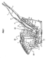
- Fig. 1 is a sectional view showing a structure of an image processing apparatus of the embodiment of the invention.
- the image processing apparatus will be explained while taking the case of a facsimile machine.
- recording materials P and originals S are set.
- the facsimile machine 100 includes an image recording unit 101 having a cartridge 1 as an example of recording means, an image reading apparatus 102 having an image reading unit 28 as an example of reading means, and an automatic feeder unit 103 which separates the plurality of recording materials P or originals S one-sheet by one-sheet from each other and conveys the same to the image recording unit 101 or the image reading apparatus 102.
- the automatic feeder unit 103 is provided at its downstream portion with a PE sensor lever 21 (Page End sensor lever) for detecting the recording materials P (or originals S), a conveyance unit for conveying the sheets at predetermined speed in the image recording unit 101 and the image reading apparatus 102, and a discharge unit for discharging the recorded and read sheets out from the apparatus.
- the conveyance unit comprises a conveyance roller 10 including a metal shaft and a rubber roller, and a plurality of pinch rollers 16 disposed in a widthwise direction of the sheet which are biased against the conveyance roller 10.
- the discharge unit comprises a discharge roller 17 in which an elastomer is integrally molded around a plastic shaft, and a spur 18 biased against the discharge roller 17-
- a platen 3 is provided as a paper-through surface from a paper-through surface of the ASF base 80 to the discharge roller 17.
- the platen 3 is formed at its recording material support surface with a plurality of ribs 38 in the widthwise direction of the recording material. When the recording materials are conveyed, the recording materials P pass through the upper surfaces of the ribs 38.
- the conveyance passage extending from the supply roller 81 to the discharge roller 17 is a common conveyance passage through which both the originals and the recording materials pass.
- the image recording unit 101 is of an ink-jet recording type which discharges ink from the cartridge 1 to record.
- the cartridge 1 is mounted on a carriage 4, and scans in a widthwise direction intersecting with the conveyance direction of the recording materials P.
- the present invention is applied to a serial type recording apparatus which moves a recording heat in a main scanning direction.
- the present invention can also be applied to a full-line type recording apparatus which uses a recording heat extending over the entire region of the sheet in its widthwise direction to record an image by the recording head while continuously conveying a recording sheet.
- the image reading unit 28 of the image reading apparatus 102 includes a contact image sensor (CS22, hereinafter) which is image reading means, a CS holder 26 which is a member holding the CS22, and a white reference member 25 which is held by the CS holder 26 such that the white reference member 25 is opposed to the CS22.
- the image reading unit 28 is usually at a standby position (standby state) separated from the platen 3. If the apparatus body receives a command for reading an image such as copy or sending, the image reading unit 28 turns in the direction of arrow in the drawing by driving means (not shown), and moves to a reading position opposed to the platen 3 (reading state).
- the entire facsimile machine can be reduced in size.
- the image reading unit 28 is moved to the standby position which is out from the moving region of the carriage 4, the image reading unit 28 does not interfere with the moving space of the carriage 4.
- Originals supplied to the image reading apparatus 102 are conveyed to the image reading unit 28 by the conveyance roller 10 and the pinch roller 16 which are commonly used for the recording materials.
- Fig. 2 is a perspective view showing the automatic feeder unit in which originals and recording materials are not set.
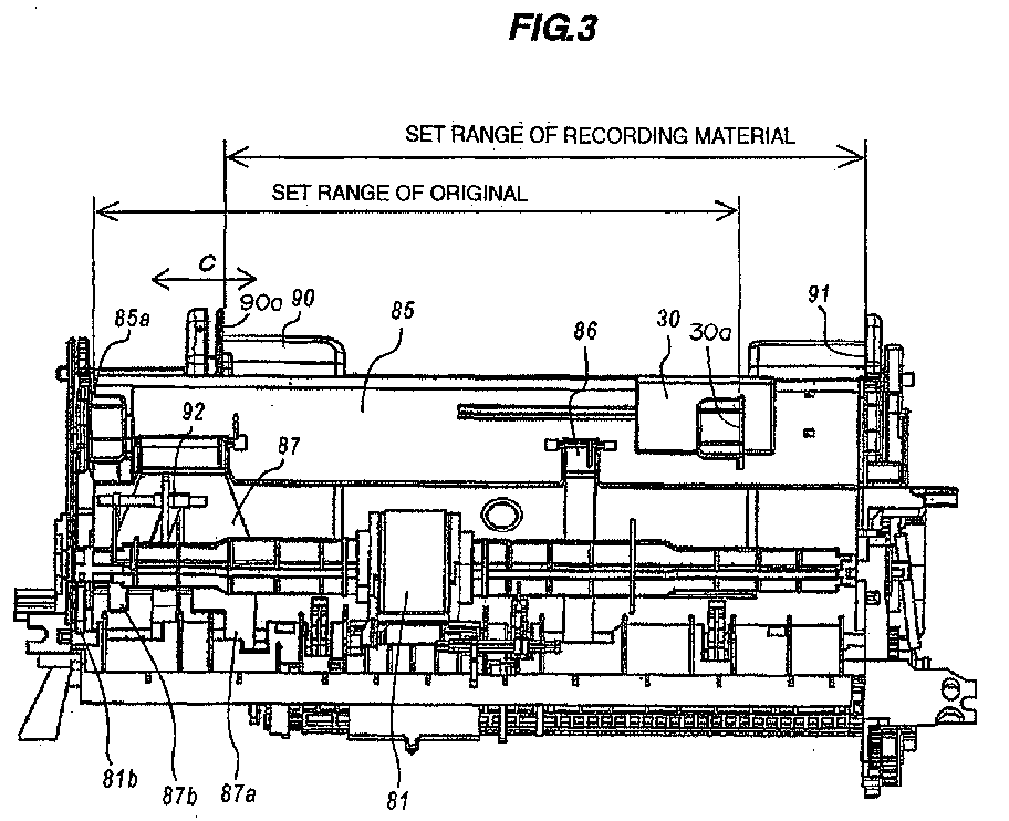
- Fig. 3 is a front view showing the automatic feeder unit when the originals and the recording materials are not set.
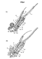
- Fig. 4 is a sectional view showing a state in which only the originals are set.
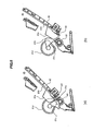
- Fig. 5 is a schematic sectional view showing motions of a pressure plate and a supply roller of the automatic feeder unit.
- Fig. 6 is a front view used for explaining a state when the paper is supplied.
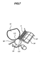
- Fig. 7 is a schematic sectional view used for explaining a separating unit.
- the ASF base 80 which is a frame of the automatic feeder unit 103 comprises a base surface 80a, a right side plate 80b, a left side plate 80c, a tip end reference surface 80d against which tip ends of the originals S and the recording materials P are abutted at the time of setting, and a paper-through surface 80e.
- a supply roller 81 and a pressure plate 82 are rotatably mounted on the right side plate 80b and the left side plate 80c through bearings.
- the pressure plate 82 is biased against the supply roller 81 by a pressure plate spring 83 mounted between a back surface of the pressure plate 82 and the base surface 80a of the ASF base 80.
- the shaft of the supply roller 81 is provided with a driving cam 81b
- the pressure plate 82 is provided with a follower cam 82a.
- the pressure plate 82 functions as a pushing member for pushing a batch of recording materials P or originals is pushed against the supply roller 81 by the pressure plate spring 83 at the time of supplying.
- the pressure plate 82 is pushed down by the follower cam 82a except when the original or recording material is supplied, a gap through which the originals and recording materials are set is formed between the pressure plate 82 and the supply roller 81, and the pressure plate 82 functions as recording material mounting means. That is, the pressure plate 82 is separated by rotation of the supply roller 81, and the driving cam 81b and the follower cam 82a constitute separating means.
- the supply roller 81 is integrally formed at its shaft with a sensor flag 81a.
- the sensor flag 81a engages with an ASF sensor (not shown) to detect a phase of the supply roller 81.
- a cross section of the supply roller 81 is a so-called D cut roller having an arc portion 81d and a straight portion 81c.
- Phases of the driving cam 81b and a semi-circular shape of the roller are designed such that the straight portion 81c and the separating pad 84 as an example of the separating means are opposed when the pressure plate 82 is separated (Fig. 4)a)), and the pressure plate 82 and the arc portion 81d of the supply roller 81 come into contact with each other at the time of biasing (Fig. 4(b)).
- a separating pad 84 is pasted on a central portion of a tip end of the pressure plate 82, and the separating pad 84 and the supply roller 81 are opposed to each other in a biasing state at the time of supplying operation. Further, as shown in Figs. 5, the separating pad 84 slightly projects from the recording material mounting surface 82b toward the supply roller 81 and in this embodiment, the separating pad 84 projects by a thickness corresponding to the maximum set number of the originals.
- a separation roller 93 as an example of separating means is disposed downstream from a nip position between the supply roller 81 and the separating pad 84 such that the separation roller 93 abuts against the supply roller 81.
- the separation roller 93 includes a torque limiter, and the separation roller 93 can be separated from and come into contact with the supply roller 81.
- the automatic feeder of this embodiment is separated through two separating means, i.e., a front separating unit and main separating unit.
- the front separating unit includes a separating pad 84 of the pressure plate 82, the supply roller 81 and the passing-limitation wall 132.
- the passing-limitation wall 132 is a barrier wall formed such that a gap of passing paper formed between the supply roller 81 and the ASF base 80 is about 1mm.
- the 50 recording materials are separated into groups each comprising several sheets by the passing-limitation wall 132, and they are conveyed to the main separating unit 131.
- the main separating unit 131 comprises the supply roller 81 and the separation roller 93, and separates the several sheets sent by the front separating unit by the above operation.
- An original stage 85 as an example of an original mounting means is detachably mounted on the pressure plate 82 at a predetermined distance from the recording material mounting surface 82b.
- An original bridge right 86 and an original bridge left 87 are rotatably mounted on the original stage 85.
- tip ends of the original bridges 86 and 87 are limited by a recess 80f of the ASF base 80 such that a predetermined gap is formed with respect to the recording material mounting surface of the pressure plate 82 (Fig. 4A).
- a recording material tray 8 is mounted on the ASF base 80 to extend a recording material mounting surface starting from the pressure plate 82.
- an original tray 88 is fixed to the original stage 85 to extend the original mounting surface.
- a slip preventing member 89 is mounted on a tip end of the original tray 88 (rear end thereof in the conveyance direction).
- a length supported by the original tray 88 and the original stage 85 is about 2/3 of the entire length of A4-size paper. When A4-size originals are set, 1/3 of rear end is free. When the paper is soft, the paper lops rearward due to its own weight as shown in Fig. 1, and its rear end is supported by the recording material tray 8.
- a side guide 90 is mounted on the pressure plate 82 such that the side guide 90 can slide in a direction of arrow C intersecting wit the conveyance direction of the recording materials P by the supply roller 81 at right angles.
- An original slider 30 is mounted on the original stage 85 also such that the original slider 30 can slide in the direction of arrow C.
- a recording material widthwise direction reference surface 91 and an original widthwise direction reference surface 85a are respectively disposed on left and right sides of the apparatus, and are relatively deviated from each other by about 30mm in the widthwise direction. Therefore, when both the recording materials and originals are set, no recording materials exist below the originals in a region of about 30mm from the reference side of the original even when recording materials having maximum width are set (Fig. 3).
- a sensor for detecting whether an original exists or not is disposed in a region where the recording materials are not set. This sensor comprises a photo interrupter 92b and a DS actuator 92 which is rotatably supported by a holder (not shown).
- this state corresponds to Fig. 4A from which the originals S are removed.
- the pressure plate 82 is moved by the driving cam 81b to a direction in which the pressure plate 82 is biased by the supply roller 81 (Fig. 5B), and the pressure plate 82 comes into contact with the uppermost recording material P.
- the original bridges 86 and 87 are located on an upper portion of the recording material, but since the original bridges 86 and 87 are located at a position where they are escaped from the supply roller in the widthwise direction, they are on standby above the supply roller so that they do not hinder the separating motion (Figs. 2 and 3).
- Fig. 4A shows a state in which both the originals S and recording materials P are set. If the supply roller rotates, the pressure plate 82 is moved by the driving cam 81b in the direction in which the pressure plate 82 is biased by the supply roller 81 (Fig. 5B), the originals S are biased through the recording materials P, and the uppermost original S comes into contact with the supply roller 81. At that time, the original bridges 86 and 87 are sandwiched between the recording material P and the original S, but the separating pad 84 projects from the recording material mounting surface 82b as shown in Fig. 6A, and the original bridges 86 and 87 escape from the supply roller 81 in the widthwise direction.
- the originals S are directly biased by the pressure plate 82 as shown in Fig. 6B, and the uppermost original S comes into contact with the supply roller 81.
- the original bridges 86 and 87 are sandwiched between the pressure plate 82 and the original S, but since the separating pad 84 projects from the recording material mounting surface 82b, the separating pad 84 and the original bridges 86 and 87 assume substantially at the same height and thus, a predetermined biasing force is applied between the original S and the supply roller 81 without excessively deforming the original.
- the separating pad 84 and the recording material mounting surface 82b assume the same height, since the original S is biased against the supply roller 81, it becomes necessary to deform the original in the widthwise direction by an amount corresponding to the thickness of the original bridges 86 and 87. In this case, the biasing force of the pressure plate 82 is used for deforming the original S, appropriate biasing force is not applied to the supply roller 81 and the supply failure is generated in some cases.
- the apparatus comprises a supply roller which supplies an original or a recording material from the original mounting means or the recording material mounting means, separating means for separating the original or the recording material in cooperation with the supply roller, and a conveyance passage through which both the original and recording material pass. Therefore, constituent members of the apparatus can commonly be used, and the apparatus can be reduced in size and cost.
- the uppermost one of the set recording materials or originals is separated, and this is conveyed to the reading means or recording means.
- the recording material is separated and conveyed, and if the originals are set above or on the recording material, the original is separated and conveyed. Therefore, in order to determine whether the automatic feeder unit separated the original or the recording material, it is absolutely necessary to detect whether the originals are set. If the originals are set, it is determined that the original is separated, and if the originals are not set, it is determined that the recording material is separated.
- the reference of the recording material and the original in the widthwise direction is laterally reversed, the setting positions of the originals and the recording materials are laterally deviated so that the recording materials are not located below the originals in a predetermined region from the reference side in the widthwise direction of the original, and the original detection sensor is disposed in a region where the originals and the recording materials are not superposed on each other.
- the reliable original detection sensor with least inexpensive structure, i.e., the photo interrupter and the actuator.
Landscapes
- Engineering & Computer Science (AREA)
- Multimedia (AREA)
- Signal Processing (AREA)
- Sheets, Magazines, And Separation Thereof (AREA)
- Controlling Sheets Or Webs (AREA)
- Facsimiles In General (AREA)
Abstract
Description
- The present invention relates to an apparatus structure in an image processing apparatus such as a facsimile machine in which an original and a recording material have a common conveyance passage.
- Conventionally, there is proposed an image processing apparatus such as a facsimile machine in which an original and a recording material have a common conveyance passage for the sake of reducing in size and cost of the image processing apparatus.
- Fig. 8 shows one example of the structure. The image processing apparatus shown in Fig. 8 includes an ASF UNIT 301 for separating and conveying a batch of recording materials mounted in a mount one-sheet by one-sheet, and ADF UNIT 302 for separating and conveying a batch of mounted originals one-sheet by one-sheet, an
auxiliary conveyance roller 303 for conveying the recording material or original conveyed from the ASF UNIT 301 or the ADF UNIT 302, amain conveyance roller 304 for conveying the recording material or the original at a predetermined speed, adischarge roller 305 for discharging the original or the recording material out from the apparatus, ascanner unit 306 for reading data of the original, and arecording unit 307 for forming an image on the recording material. In the above structure, a guide member forms theauxiliary conveyance roller 303, themain conveyance roller 304, thedischarge roller 305 and a conveyance passage, and the guide member is commonly used for both originals and recording materials so that the apparatus is reduced in size and cost. A facsimile machine having such a structure is proposed in U.S.P.5727890. - There is proposed a structure for supplying recording materials from a cassette and a manual feeder opening by controlling rotation and turning motion of one supply roller (Japanese Patent Application Laid-open No. H03-243545). According to the structure described in Japanese Patent Application Laid-open No. H03-243545, the supply roller can be turned and moved between two recording material mounting means so that the recording material can be supplied from any of the mounting means.
- In the structure of U.S.P.5727890, however, since the
scanner unit 306 is disposed upstream from themain conveyance roller 304, theauxiliary conveyance roller 303 is provided for making up unstable conveying speed of the ADF UNIT 302 and for conveying the original to themain conveyance roller 304. Therefore, as compared with a structure in which the original and the recording material comprise different conveyance means and conveyance passages, only thedischarge roller 305 is commonly used, and the apparatus can not sufficiently be reduced in cost and size. - According to the structure of Japanese Patent Application Laid-open No. H03-243545, the mechanism for turning the supply roller and the control manner thereof are complicated, and each mounting means must have the separating means. Therefore, the apparatus can not be sufficiently reduced in cost and size.
- It is an object of the present invention to provide an image processing apparatus capable of separately supplying both the originals and recording materials by one set of separating/supplying mechanism, and capable of inexpensively and reliably detecting the originals irrespective of presence or absence of the recording materials.
- To achieve the above object, a typical structure of an image processing apparatus of the present invention comprises original mounting means for mounting originals, a recording material mounting means for mounting recording materials, a supply roller for supplying the originals or recording materials from the original mounting means or the recording material mounting means, separating means for separating the original or the recording material in cooperation with the supply roller, reading means reading an image of the original, recording means for recording the image on the recording material, and a original detection sensor for detecting the original on the original mounting means, the original mounting means and the recording material mounting means are disposed between the supply roller and the separating means, references of the original mounting means and the recording material mounting means in their widthwise directions are one-sided reference, a reference surface of the original mounting means and a reference surface of the recording material mounting means are set on opposite sides with respect to the apparatus, and the original detection sensor is disposed in a region where no recording material is mounted.
- According to the present invention, in the image processing apparatus having the reading means and recording means, the supply roller, the separating means and the conveyance passage for separating and supplying the originals and the recording materials can commonly be used. Therefore, the apparatus can be reduced in size and cost. Irrespective of the fact that these elements are commonly used and irrespective of whether there exists the recording material, it is possible to inexpensively and reliably detect the original.
-
- Fig. 1 a sectional view showing a structure of an image processing apparatus of an embodiment;
- Fig. 2 is a perspective view showing an automatic feeder unit when originals and recording materials are not set;
- Fig. 3 is a front view showing the automatic feeder unit when the originals and the recording materials are not set;
- Figs. 4 are sectional views showing a state in which only the originals are set;
- Figs. 5 are schematic sectional views showing motions of a pressure plate and a supply roller of the automatic feeder unit;
- Figs. 6 are front views used for explaining a state when the paper is supplied;
- Fig. 7 is a schematic sectional view used for explaining a separating unit; and
- Fig. 8 is a diagram showing an example of a conventional image processing apparatus.
-
- An embodiment of the present invention will be explained in detail using the drawings. The scope of the invention is not limited to sizes, materials, shapes and relative positions of constituent elements described in the embodiment unless otherwise specified.
- Fig. 1 is a sectional view showing a structure of an image processing apparatus of the embodiment of the invention. The image processing apparatus will be explained while taking the case of a facsimile machine. In the
facsimile machine 100 shown in the drawings, recording materials P and originals S are set. Thefacsimile machine 100 includes animage recording unit 101 having a cartridge 1 as an example of recording means, animage reading apparatus 102 having animage reading unit 28 as an example of reading means, and anautomatic feeder unit 103 which separates the plurality of recording materials P or originals S one-sheet by one-sheet from each other and conveys the same to theimage recording unit 101 or theimage reading apparatus 102. - The
automatic feeder unit 103 is provided at its downstream portion with a PE sensor lever 21 (Page End sensor lever) for detecting the recording materials P (or originals S), a conveyance unit for conveying the sheets at predetermined speed in theimage recording unit 101 and theimage reading apparatus 102, and a discharge unit for discharging the recorded and read sheets out from the apparatus. The conveyance unit comprises a conveyance roller 10 including a metal shaft and a rubber roller, and a plurality of pinch rollers 16 disposed in a widthwise direction of the sheet which are biased against the conveyance roller 10. The discharge unit comprises adischarge roller 17 in which an elastomer is integrally molded around a plastic shaft, and aspur 18 biased against the discharge roller 17-A platen 3 is provided as a paper-through surface from a paper-through surface of theASF base 80 to thedischarge roller 17. Theplaten 3 is formed at its recording material support surface with a plurality of ribs 38 in the widthwise direction of the recording material. When the recording materials are conveyed, the recording materials P pass through the upper surfaces of the ribs 38. The conveyance passage extending from thesupply roller 81 to thedischarge roller 17 is a common conveyance passage through which both the originals and the recording materials pass. - The
image recording unit 101 is of an ink-jet recording type which discharges ink from the cartridge 1 to record. The cartridge 1 is mounted on a carriage 4, and scans in a widthwise direction intersecting with the conveyance direction of the recording materials P. In this embodiment, the present invention is applied to a serial type recording apparatus which moves a recording heat in a main scanning direction. The present invention can also be applied to a full-line type recording apparatus which uses a recording heat extending over the entire region of the sheet in its widthwise direction to record an image by the recording head while continuously conveying a recording sheet. - The
image reading unit 28 of theimage reading apparatus 102 includes a contact image sensor (CS22, hereinafter) which is image reading means, aCS holder 26 which is a member holding the CS22, and awhite reference member 25 which is held by theCS holder 26 such that thewhite reference member 25 is opposed to the CS22. Theimage reading unit 28 is usually at a standby position (standby state) separated from theplaten 3. If the apparatus body receives a command for reading an image such as copy or sending, theimage reading unit 28 turns in the direction of arrow in the drawing by driving means (not shown), and moves to a reading position opposed to the platen 3 (reading state). By providing theimage reading unit 28 in a moving path of the carriage 4, the entire facsimile machine can be reduced in size. During the image-recording operation, theimage reading unit 28 is moved to the standby position which is out from the moving region of the carriage 4, theimage reading unit 28 does not interfere with the moving space of the carriage 4. - Originals supplied to the
image reading apparatus 102 are conveyed to theimage reading unit 28 by the conveyance roller 10 and the pinch roller 16 which are commonly used for the recording materials. The originals S sandwiched and conveyed by the conveyance roller 10 and the pinch roller 16, as well as thedischarge roller 17 and thespur 18, the reading operation is carried out by theimage reading unit 28 and the originals S are discharged out from the apparatus. - The (automatic feeder unit)
automatic feeder unit 103 will be explained. Fig. 2 is a perspective view showing the automatic feeder unit in which originals and recording materials are not set. Fig. 3 is a front view showing the automatic feeder unit when the originals and the recording materials are not set. Fig. 4 is a sectional view showing a state in which only the originals are set. Fig. 5 is a schematic sectional view showing motions of a pressure plate and a supply roller of the automatic feeder unit. Fig. 6 is a front view used for explaining a state when the paper is supplied. Fig. 7 is a schematic sectional view used for explaining a separating unit. - As shown in Figs. 2 and 4A, the
ASF base 80 which is a frame of theautomatic feeder unit 103 comprises abase surface 80a, aright side plate 80b, aleft side plate 80c, a tipend reference surface 80d against which tip ends of the originals S and the recording materials P are abutted at the time of setting, and a paper-throughsurface 80e. - A
supply roller 81 and apressure plate 82 are rotatably mounted on theright side plate 80b and theleft side plate 80c through bearings. Thepressure plate 82 is biased against thesupply roller 81 by apressure plate spring 83 mounted between a back surface of thepressure plate 82 and thebase surface 80a of the ASFbase 80. - As shown in Figs. 2 and 5, the shaft of the
supply roller 81 is provided with a drivingcam 81b, and thepressure plate 82 is provided with afollower cam 82a. As shown in Fig. 5A, thepressure plate 82 functions as a pushing member for pushing a batch of recording materials P or originals is pushed against thesupply roller 81 by thepressure plate spring 83 at the time of supplying. Further, as shown in Fig. 5B, thepressure plate 82 is pushed down by thefollower cam 82a except when the original or recording material is supplied, a gap through which the originals and recording materials are set is formed between thepressure plate 82 and thesupply roller 81, and thepressure plate 82 functions as recording material mounting means. That is, thepressure plate 82 is separated by rotation of thesupply roller 81, and the drivingcam 81b and thefollower cam 82a constitute separating means. - The
supply roller 81 is integrally formed at its shaft with asensor flag 81a. Thesensor flag 81a engages with an ASF sensor (not shown) to detect a phase of thesupply roller 81. A cross section of thesupply roller 81 is a so-called D cut roller having anarc portion 81d and astraight portion 81c. Phases of the drivingcam 81b and a semi-circular shape of the roller are designed such that thestraight portion 81c and theseparating pad 84 as an example of the separating means are opposed when thepressure plate 82 is separated (Fig. 4)a)), and thepressure plate 82 and thearc portion 81d of thesupply roller 81 come into contact with each other at the time of biasing (Fig. 4(b)). - A
separating pad 84 is pasted on a central portion of a tip end of thepressure plate 82, and theseparating pad 84 and thesupply roller 81 are opposed to each other in a biasing state at the time of supplying operation. Further, as shown in Figs. 5, theseparating pad 84 slightly projects from the recordingmaterial mounting surface 82b toward thesupply roller 81 and in this embodiment, theseparating pad 84 projects by a thickness corresponding to the maximum set number of the originals. - A
separation roller 93 as an example of separating means is disposed downstream from a nip position between thesupply roller 81 and theseparating pad 84 such that theseparation roller 93 abuts against thesupply roller 81. Theseparation roller 93 includes a torque limiter, and theseparation roller 93 can be separated from and come into contact with thesupply roller 81. As shown in Fig. 7, the automatic feeder of this embodiment is separated through two separating means, i.e., a front separating unit and main separating unit. The front separating unit includes aseparating pad 84 of thepressure plate 82, thesupply roller 81 and the passing-limitation wall 132. The passing-limitation wall 132 is a barrier wall formed such that a gap of passing paper formed between thesupply roller 81 and theASF base 80 is about 1mm. When 50 recording materials are set for example, the 50 recording materials are separated into groups each comprising several sheets by the passing-limitation wall 132, and they are conveyed to themain separating unit 131. Themain separating unit 131 comprises thesupply roller 81 and theseparation roller 93, and separates the several sheets sent by the front separating unit by the above operation. - An
original stage 85 as an example of an original mounting means is detachably mounted on thepressure plate 82 at a predetermined distance from the recordingmaterial mounting surface 82b. An original bridge right 86 and an original bridge left 87 are rotatably mounted on theoriginal stage 85. In a state in which theoriginal stage 85 is mounted on thepressure plate 82, tip ends of theoriginal bridges recess 80f of theASF base 80 such that a predetermined gap is formed with respect to the recording material mounting surface of the pressure plate 82 (Fig. 4A). - A
recording material tray 8 is mounted on theASF base 80 to extend a recording material mounting surface starting from thepressure plate 82. Similarly, anoriginal tray 88 is fixed to theoriginal stage 85 to extend the original mounting surface. Aslip preventing member 89 is mounted on a tip end of the original tray 88 (rear end thereof in the conveyance direction). A length supported by theoriginal tray 88 and theoriginal stage 85 is about 2/3 of the entire length of A4-size paper. When A4-size originals are set, 1/3 of rear end is free. When the paper is soft, the paper lops rearward due to its own weight as shown in Fig. 1, and its rear end is supported by therecording material tray 8. - As shown in Fig. 3, a
side guide 90 is mounted on thepressure plate 82 such that theside guide 90 can slide in a direction of arrow C intersecting wit the conveyance direction of the recording materials P by thesupply roller 81 at right angles. Anoriginal slider 30 is mounted on theoriginal stage 85 also such that theoriginal slider 30 can slide in the direction of arrow C. When the recording materials are to be set, concerning the widthwise direction, right sides of the recording materials are abutted against a recording material widthwisedirection reference surface 91 formed on thepressure plate 82, left sides of the recording materials are limited by a guide surface 90a of theside guide 90, tip ends of the recording materials are supported by the tipend reference surface 80d, and the entire recording materials are supported by therecording material tray 8 and the recordingmaterial mounting surface 82b of the pressure plate 82 (Figs. 1 and 3). When the originals are to be set, left sides of the originals are abutted against the original widthwisedirection reference surface 85a formed on theoriginal stage 85, right sides of the originals are limited by aguide surface 30a of theoriginal slider 30, tip ends of the originals are supported by the tipend reference surface 80d, and the entire originals are supported by theoriginal tray 88, theoriginal stage 85, and theoriginal bridges 86 and 87 (Figs. 1, 3 and 4). - A recording material widthwise
direction reference surface 91 and an original widthwisedirection reference surface 85a are respectively disposed on left and right sides of the apparatus, and are relatively deviated from each other by about 30mm in the widthwise direction. Therefore, when both the recording materials and originals are set, no recording materials exist below the originals in a region of about 30mm from the reference side of the original even when recording materials having maximum width are set (Fig. 3). A sensor for detecting whether an original exists or not is disposed in a region where the recording materials are not set. This sensor comprises aphoto interrupter 92b and aDS actuator 92 which is rotatably supported by a holder (not shown). If originals are set, the originals and anarm 92a abut against each other, anactuator 92 rotates, asensor flag 92b selectively cuts off optical path of aphoto interrupter 92c, thereby turning the sensor ON or OFF (Fig. 1). A tip end of the original bridge left 87 is bifurcated, one (87a) of the bifurcated end comes above the set recording materials, and theother end 87b is located at a position where there is no recording material. An arm of theDS actuator 92 moves between the bifurcated ends (Fig. 2). - When only the recording materials are set, this state corresponds to Fig. 4A from which the originals S are removed. If the supply roller rotates, the
pressure plate 82 is moved by the drivingcam 81b to a direction in which thepressure plate 82 is biased by the supply roller 81 (Fig. 5B), and thepressure plate 82 comes into contact with the uppermost recording material P. At that time, theoriginal bridges original bridges - Fig. 4A shows a state in which both the originals S and recording materials P are set. If the supply roller rotates, the
pressure plate 82 is moved by the drivingcam 81b in the direction in which thepressure plate 82 is biased by the supply roller 81 (Fig. 5B), the originals S are biased through the recording materials P, and the uppermost original S comes into contact with thesupply roller 81. At that time, theoriginal bridges separating pad 84 projects from the recordingmaterial mounting surface 82b as shown in Fig. 6A, and theoriginal bridges supply roller 81 in the widthwise direction. Therefore, a predetermined biasing force is applied between the original S and thesupply roller 81 without excessively deforming the original. Although there is no recording material P below a region of about 30mm of the original S on the reference side, since the original is supported by the original bridge left 87, the original does not lop downward. This is because that the original bridge left 87 is bifurcated as described above and one of them comes over the recording material P and limits its position. The originals can be supported in accordance with change of the number of set recording materials P. - When only the originals S are set, the originals S are directly biased by the
pressure plate 82 as shown in Fig. 6B, and the uppermost original S comes into contact with thesupply roller 81. At that time, theoriginal bridges pressure plate 82 and the original S, but since theseparating pad 84 projects from the recordingmaterial mounting surface 82b, theseparating pad 84 and theoriginal bridges supply roller 81 without excessively deforming the original. If theseparating pad 84 and the recordingmaterial mounting surface 82b assume the same height, since the original S is biased against thesupply roller 81, it becomes necessary to deform the original in the widthwise direction by an amount corresponding to the thickness of theoriginal bridges pressure plate 82 is used for deforming the original S, appropriate biasing force is not applied to thesupply roller 81 and the supply failure is generated in some cases. - According to the present invention, as explained above, the apparatus comprises a supply roller which supplies an original or a recording material from the original mounting means or the recording material mounting means, separating means for separating the original or the recording material in cooperation with the supply roller, and a conveyance passage through which both the original and recording material pass. Therefore, constituent members of the apparatus can commonly be used, and the apparatus can be reduced in size and cost.
- According to the above-described structure, the uppermost one of the set recording materials or originals is separated, and this is conveyed to the reading means or recording means. Thus, if only the recording materials are set, the recording material is separated and conveyed, and if the originals are set above or on the recording material, the original is separated and conveyed. Therefore, in order to determine whether the automatic feeder unit separated the original or the recording material, it is absolutely necessary to detect whether the originals are set. If the originals are set, it is determined that the original is separated, and if the originals are not set, it is determined that the recording material is separated. Thereupon, according to the present invention, the reference of the recording material and the original in the widthwise direction is laterally reversed, the setting positions of the originals and the recording materials are laterally deviated so that the recording materials are not located below the originals in a predetermined region from the reference side in the widthwise direction of the original, and the original detection sensor is disposed in a region where the originals and the recording materials are not superposed on each other. Thus, even if both the originals and the recording materials are set, since there is sufficient space below the originals, it is possible to dispose the reliable original detection sensor with least inexpensive structure, i.e., the photo interrupter and the actuator.
- This application claims the benefit of priority from the prior Japanese Patent Application No. 2004-184536 filed on June 23, 2004 the entire contents of which are incorporated herein by reference.
Claims (10)
- An image processing apparatus comprising
original mounting means for mounting originals,
recording material mounting means for mounting recording materials,
a supply roller for supplying the originals or recording materials from the original mounting means or the recording material mounting means,
separating means for separating the original or the recording material in cooperation with the supply roller,
reading means reading an image of the original,
recording means for recording the image on the recording material, and
a original detection sensor for detecting the original on the original mounting means, wherein
the original mounting means and the recording material mounting means are disposed between the supply roller and the separating means, references of the original mounting means and the recording material mounting means in their widthwise directions are one-sided reference, a reference surface of the original mounting means and a reference surface of the recording material mounting means are set on opposite sides with respect to the apparatus,
the original detection sensor is disposed in a region where no recording material is mounted. - The image processing apparatus according to claim 1, wherein a distance between the reference surface of the original mounting means and the reference surface of the recording material mounting means is wider than a width of the maximum recording materials which can be conveyed by an apparatus body.
- An image processing apparatus comprising:recording material mounting means for mounting recording materials;original mounting means for mounting originals on a position superposed on the recording materials mounted by the recording material mounting means;a supply roller for supplying the original or the recording material from the original mounting means or the recording material mounting means;separating means for separating the original or the recording material in cooperation with the supply roller;an original detection sensor disposed above the original mounting means for detecting the original on the original mounting means; andposition limiting means for limiting a position of the original so that a portion of the original on the original mounting means is not superposed on the recording material on the recording material mounting means; whereinthe original detection sensor detects that portion of the original mounted on the original mounting means which is not superposed on the recording material.
- The image processing apparatus according to claim 3, wherein the original detection sensor is rockably provided, and a rocking end of the original detection sensor has an arm which is put on that portion of the original mounted on the original mounting means which is not superposed with the recording material.
- The image processing apparatus according to claim 4, wherein the original detection sensor includes a switch which is switched in accordance with rocking motion of the arm.
- The image processing apparatus according to claim 4, wherein the original detection sensor includes a photo interrupter, and a light shielding member for shielding an optical path of the photo interrupter in association with the rocking motion of the arm.
- The image processing apparatus according to claim 3, wherein when the original is not mounted on the original mounting means, the recording material mounting means pushes the recording material mounted on the recording material mounting means against the supply roller.
- The image processing apparatus according to claim 3, wherein when the original is mounted on the original mounting means, the recording material mounting means pushes up the original mounting means directly or through the recording material mounted on the recording material mounting means, and pushes the original mounted on the original mounting means against the supply roller.
- The image processing apparatus according to claim 8, wherein the original mounting means includes a plate member on which the original is mounted, the plate member is pushed up directly by the recording material mounting means or through the recording material mounted on the recording material mounting means.
- The image processing apparatus according to claim 9, wherein the plate member is integrally formed with a portion which is pushed up by the recording material mounting means and a portion which supports a portion of the original that is not superposed on the recording material.
Applications Claiming Priority (2)
| Application Number | Priority Date | Filing Date | Title |
|---|---|---|---|
| JP2004184536A JP4307338B2 (en) | 2004-06-23 | 2004-06-23 | Image processing device |
| JP2004184536 | 2004-06-23 |
Publications (2)
| Publication Number | Publication Date |
|---|---|
| EP1610541A1 true EP1610541A1 (en) | 2005-12-28 |
| EP1610541B1 EP1610541B1 (en) | 2011-10-05 |
Family
ID=34937560
Family Applications (1)
| Application Number | Title | Priority Date | Filing Date |
|---|---|---|---|
| EP05013275A Expired - Lifetime EP1610541B1 (en) | 2004-06-23 | 2005-06-20 | Reliable detection of originals in an image processing apparatus with a single mechanism for separating and supplying both originals and recording materials |
Country Status (5)
| Country | Link |
|---|---|
| US (1) | US8081919B2 (en) |
| EP (1) | EP1610541B1 (en) |
| JP (1) | JP4307338B2 (en) |
| KR (1) | KR100748281B1 (en) |
| CN (1) | CN100351094C (en) |
Cited By (1)
| Publication number | Priority date | Publication date | Assignee | Title |
|---|---|---|---|---|
| WO2008086485A2 (en) | 2007-01-10 | 2008-07-17 | Marvell World Trade Ltd. | Discerning between original media and blank media in a common feed path printer device |
Families Citing this family (3)
| Publication number | Priority date | Publication date | Assignee | Title |
|---|---|---|---|---|
| JP4307338B2 (en) | 2004-06-23 | 2009-08-05 | キヤノン株式会社 | Image processing device |
| JP4500727B2 (en) * | 2005-04-28 | 2010-07-14 | キヤノン株式会社 | Image reading and recording device |
| JP6478466B2 (en) * | 2014-03-03 | 2019-03-06 | キヤノン株式会社 | Reader |
Citations (1)
| Publication number | Priority date | Publication date | Assignee | Title |
|---|---|---|---|---|
| US5727890A (en) * | 1993-10-29 | 1998-03-17 | Hewlett-Packard Company | Multiple-function printer with common mounting chassis feeder/output path mechanisms |
Family Cites Families (35)
| Publication number | Priority date | Publication date | Assignee | Title |
|---|---|---|---|---|
| JPS5767431A (en) | 1980-10-09 | 1982-04-24 | Canon Inc | Feeding device |
| JPS5961948U (en) * | 1982-10-18 | 1984-04-23 | 株式会社東芝 | Paper feeding device |
| JPS61128233A (en) | 1984-11-27 | 1986-06-16 | Asahi Optical Co Ltd | Signal transmitting means between camera body and accessory |
| JPH0657464B2 (en) * | 1985-04-09 | 1994-08-03 | ブラザー工業株式会社 | Printer |
| JPH0748120B2 (en) | 1988-08-12 | 1995-05-24 | シャープ株式会社 | Copier developing device |
| JPH02257755A (en) | 1989-03-30 | 1990-10-18 | Toshiba Corp | Image forming device |
| JP2928309B2 (en) | 1990-02-20 | 1999-08-03 | キヤノン株式会社 | Recording device |
| US5427462A (en) * | 1991-04-16 | 1995-06-27 | Hewlett-Packard Company | Method and apparatus for paper control and skew correction in a printer |
| JP3131702B2 (en) * | 1991-09-30 | 2001-02-05 | 京セラミタ株式会社 | Automatic document feeder |
| WO1994006804A1 (en) | 1992-09-18 | 1994-03-31 | Otsuka Kagaku Kabushiki Kaisha | Cephem compound, process for producing the same, and medicine containing the same |
| JP3243545B2 (en) | 1992-09-18 | 2002-01-07 | 大塚化学株式会社 | Cephem compound, method for producing the same, and medicament containing the compound |
| JP3359077B2 (en) | 1993-03-02 | 2002-12-24 | キヤノン株式会社 | Image forming apparatus and method of controlling image forming apparatus |
| DE69404801T2 (en) | 1993-10-29 | 1998-03-12 | Hewlett Packard Co | Multi-function printer with common input / output path |
| US5738454A (en) | 1993-10-29 | 1998-04-14 | Hewlett-Packard Company | Multiple-function printer with common output path mechanism with floating guide ribs to accommodate media and documents of different thickness |
| US5391009A (en) | 1993-10-29 | 1995-02-21 | Hewlett-Packard Company | Single motor actuation for automatic stack feeder system in a hardcopy device |
| US5651623A (en) | 1993-10-29 | 1997-07-29 | Hewlett-Packard Company | Multiple-function printer with common feeder/output path mechanisms and method of operation |
| JPH08119471A (en) | 1994-10-20 | 1996-05-14 | Canon Inc | Fax machine |
| US5587812A (en) | 1993-12-13 | 1996-12-24 | Canon Kabushiki Kaisha | Facsimile apparatus with common sheet conveying path |
| US5728890A (en) * | 1994-06-10 | 1998-03-17 | Ube Industries, Ltd. | Process for producing a cycloalkanol and cycloalkanone |
| DE69512574T2 (en) | 1994-07-06 | 2000-05-04 | Canon K.K., Tokio/Tokyo | Imaging device with a priority interrupt controller |
| JP3501503B2 (en) | 1994-07-25 | 2004-03-02 | キヤノン株式会社 | Image forming apparatus and sheet post-processing apparatus |
| JP3471935B2 (en) | 1994-11-11 | 2003-12-02 | キヤノン株式会社 | Image forming apparatus and image layout determining method |
| JPH08214110A (en) | 1995-02-06 | 1996-08-20 | Matsushita Graphic Commun Syst Inc | Facsimile equipment |
| US6134417A (en) * | 1997-03-14 | 2000-10-17 | Nisca Corporation | Automatic document feeding apparatus for simplex, duplex and 2-in-1 document handling |
| JP3281568B2 (en) | 1997-03-27 | 2002-05-13 | キヤノン株式会社 | Sheet material transport device and image processing device |
| JPH1135226A (en) * | 1997-07-18 | 1999-02-09 | Fujitsu Ltd | Discharge medium detection device, medium conveyance device having this device, and image forming apparatus |
| JP4217340B2 (en) | 1999-04-15 | 2009-01-28 | キヤノン株式会社 | Sheet material detecting apparatus, sheet material conveying apparatus, and image forming apparatus |
| US7433091B2 (en) * | 2002-11-28 | 2008-10-07 | Canon Kabushiki Kaisha | Image forming and reading apparatus |
| JP4353501B2 (en) | 2002-11-29 | 2009-10-28 | Idec株式会社 | Indicator light |
| JP2004184538A (en) | 2002-11-29 | 2004-07-02 | Fujikura Ltd | Optical cable |
| JP4058335B2 (en) | 2002-12-24 | 2008-03-05 | キヤノン株式会社 | Image reading and recording device |
| JP4115268B2 (en) | 2002-12-24 | 2008-07-09 | キヤノン株式会社 | Image reading and recording device |
| JP2004203509A (en) | 2002-12-24 | 2004-07-22 | Canon Inc | Sheet feeding device and image reading / recording device provided with the same |
| JP4307338B2 (en) | 2004-06-23 | 2009-08-05 | キヤノン株式会社 | Image processing device |
| JP4194536B2 (en) | 2004-06-23 | 2008-12-10 | キヤノン株式会社 | Image processing device |
-
2004
- 2004-06-23 JP JP2004184536A patent/JP4307338B2/en not_active Expired - Fee Related
-
2005
- 2005-06-20 EP EP05013275A patent/EP1610541B1/en not_active Expired - Lifetime
- 2005-06-21 US US11/156,448 patent/US8081919B2/en not_active Expired - Fee Related
- 2005-06-23 KR KR1020050054219A patent/KR100748281B1/en not_active Expired - Fee Related
- 2005-06-23 CN CNB2005100774658A patent/CN100351094C/en not_active Expired - Fee Related
Patent Citations (1)
| Publication number | Priority date | Publication date | Assignee | Title |
|---|---|---|---|---|
| US5727890A (en) * | 1993-10-29 | 1998-03-17 | Hewlett-Packard Company | Multiple-function printer with common mounting chassis feeder/output path mechanisms |
Cited By (3)
| Publication number | Priority date | Publication date | Assignee | Title |
|---|---|---|---|---|
| WO2008086485A2 (en) | 2007-01-10 | 2008-07-17 | Marvell World Trade Ltd. | Discerning between original media and blank media in a common feed path printer device |
| WO2008086485A3 (en) * | 2007-01-10 | 2009-07-16 | Marvell World Trade Ltd | Discerning between original media and blank media in a common feed path printer device |
| US8991812B2 (en) | 2007-01-10 | 2015-03-31 | Marvell World Trade Ltd. | Discerning between original media and blank media in a common feed path printer device |
Also Published As
| Publication number | Publication date |
|---|---|
| US8081919B2 (en) | 2011-12-20 |
| CN100351094C (en) | 2007-11-28 |
| CN1712229A (en) | 2005-12-28 |
| JP2006013654A (en) | 2006-01-12 |
| US20050286943A1 (en) | 2005-12-29 |
| KR100748281B1 (en) | 2007-08-09 |
| JP4307338B2 (en) | 2009-08-05 |
| EP1610541B1 (en) | 2011-10-05 |
| KR20060048482A (en) | 2006-05-18 |
Similar Documents
| Publication | Publication Date | Title |
|---|---|---|
| EP2466867B1 (en) | Image forming apparatus | |
| US7584950B2 (en) | Image forming apparatus and sheet feeding cassette | |
| US20020098023A1 (en) | Image reading apparatus | |
| CN1314543C (en) | Recording medium conveying device and image forming apparatus including the same | |
| US7618035B2 (en) | Image recording apparatus | |
| JP2007223735A (en) | Image recording device | |
| JP3669437B2 (en) | Paper feeding device and printing device equipped with the paper feeding device | |
| KR100656323B1 (en) | Image processing apparatus | |
| EP1610541B1 (en) | Reliable detection of originals in an image processing apparatus with a single mechanism for separating and supplying both originals and recording materials | |
| US11535468B2 (en) | Recording apparatus | |
| US20230234803A1 (en) | Printing apparatus | |
| US7922166B2 (en) | Image reader | |
| JP4779751B2 (en) | Image recording device | |
| JP4065519B2 (en) | Image reading and recording device | |
| JP4701785B2 (en) | Image recording device | |
| JP7815674B2 (en) | Image recording device | |
| JP2001233473A (en) | Paper feeding device, recording device, and paper feeding method | |
| JPH07143279A (en) | Fax machine | |
| JP2006086698A (en) | Image processing device | |
| JP2004202892A (en) | Image reading and recording device | |
| JP2004180143A (en) | Image reading and recording device | |
| JP2002255384A (en) | Sheet material feeder | |
| JPH086320A (en) | Document feeder | |
| JP2004231369A (en) | Image recording device | |
| JP2000177872A (en) | Document feeder |
Legal Events
| Date | Code | Title | Description |
|---|---|---|---|
| PUAI | Public reference made under article 153(3) epc to a published international application that has entered the european phase |
Free format text: ORIGINAL CODE: 0009012 |
|
| AK | Designated contracting states |
Kind code of ref document: A1 Designated state(s): AT BE BG CH CY CZ DE DK EE ES FI FR GB GR HU IE IS IT LI LT LU MC NL PL PT RO SE SI SK TR |
|
| AX | Request for extension of the european patent |
Extension state: AL BA HR LV MK YU |
|
| 17P | Request for examination filed |
Effective date: 20060628 |
|
| AKX | Designation fees paid |
Designated state(s): DE FR GB IT |
|
| 17Q | First examination report despatched |
Effective date: 20071122 |
|
| GRAC | Information related to communication of intention to grant a patent modified |
Free format text: ORIGINAL CODE: EPIDOSCIGR1 |
|
| GRAP | Despatch of communication of intention to grant a patent |
Free format text: ORIGINAL CODE: EPIDOSNIGR1 |
|
| RIN1 | Information on inventor provided before grant (corrected) |
Inventor name: AWAI, TAKASHI Inventor name: SUZUKI, YOSHIAKI Inventor name: TERASHIMA, HIDEYUKI |
|
| GRAS | Grant fee paid |
Free format text: ORIGINAL CODE: EPIDOSNIGR3 |
|
| GRAA | (expected) grant |
Free format text: ORIGINAL CODE: 0009210 |
|
| AK | Designated contracting states |
Kind code of ref document: B1 Designated state(s): DE FR GB IT |
|
| REG | Reference to a national code |
Ref country code: GB Ref legal event code: FG4D |
|
| REG | Reference to a national code |
Ref country code: DE Ref legal event code: R096 Ref document number: 602005030318 Country of ref document: DE Effective date: 20111215 |
|
| PLBE | No opposition filed within time limit |
Free format text: ORIGINAL CODE: 0009261 |
|
| STAA | Information on the status of an ep patent application or granted ep patent |
Free format text: STATUS: NO OPPOSITION FILED WITHIN TIME LIMIT |
|
| PG25 | Lapsed in a contracting state [announced via postgrant information from national office to epo] |
Ref country code: IT Free format text: LAPSE BECAUSE OF FAILURE TO SUBMIT A TRANSLATION OF THE DESCRIPTION OR TO PAY THE FEE WITHIN THE PRESCRIBED TIME-LIMIT Effective date: 20111005 |
|
| 26N | No opposition filed |
Effective date: 20120706 |
|
| REG | Reference to a national code |
Ref country code: DE Ref legal event code: R097 Ref document number: 602005030318 Country of ref document: DE Effective date: 20120706 |
|
| PGFP | Annual fee paid to national office [announced via postgrant information from national office to epo] |
Ref country code: GB Payment date: 20140610 Year of fee payment: 10 |
|
| PGFP | Annual fee paid to national office [announced via postgrant information from national office to epo] |
Ref country code: DE Payment date: 20140630 Year of fee payment: 10 |
|
| PGFP | Annual fee paid to national office [announced via postgrant information from national office to epo] |
Ref country code: FR Payment date: 20140625 Year of fee payment: 10 |
|
| REG | Reference to a national code |
Ref country code: DE Ref legal event code: R119 Ref document number: 602005030318 Country of ref document: DE |
|
| GBPC | Gb: european patent ceased through non-payment of renewal fee |
Effective date: 20150620 |
|
| REG | Reference to a national code |
Ref country code: FR Ref legal event code: ST Effective date: 20160229 |
|
| PG25 | Lapsed in a contracting state [announced via postgrant information from national office to epo] |
Ref country code: GB Free format text: LAPSE BECAUSE OF NON-PAYMENT OF DUE FEES Effective date: 20150620 Ref country code: DE Free format text: LAPSE BECAUSE OF NON-PAYMENT OF DUE FEES Effective date: 20160101 |
|
| PG25 | Lapsed in a contracting state [announced via postgrant information from national office to epo] |
Ref country code: FR Free format text: LAPSE BECAUSE OF NON-PAYMENT OF DUE FEES Effective date: 20150630 |