EP1610407B1 - Secondary battery module - Google Patents
Secondary battery module Download PDFInfo
- Publication number
- EP1610407B1 EP1610407B1 EP20050105702 EP05105702A EP1610407B1 EP 1610407 B1 EP1610407 B1 EP 1610407B1 EP 20050105702 EP20050105702 EP 20050105702 EP 05105702 A EP05105702 A EP 05105702A EP 1610407 B1 EP1610407 B1 EP 1610407B1
- Authority
- EP
- European Patent Office
- Prior art keywords
- secondary battery
- barrier rib
- battery module
- protrusions
- protrusion
- Prior art date
- Legal status (The legal status is an assumption and is not a legal conclusion. Google has not performed a legal analysis and makes no representation as to the accuracy of the status listed.)
- Expired - Lifetime
Links
Images






Classifications
-
- H—ELECTRICITY
- H01—ELECTRIC ELEMENTS
- H01M—PROCESSES OR MEANS, e.g. BATTERIES, FOR THE DIRECT CONVERSION OF CHEMICAL ENERGY INTO ELECTRICAL ENERGY
- H01M50/00—Constructional details or processes of manufacture of the non-active parts of electrochemical cells other than fuel cells, e.g. hybrid cells
- H01M50/20—Mountings; Secondary casings or frames; Racks, modules or packs; Suspension devices; Shock absorbers; Transport or carrying devices; Holders
- H01M50/258—Modular batteries; Casings provided with means for assembling
- H01M50/26—Assemblies sealed to each other in a non-detachable manner
-
- H—ELECTRICITY
- H01—ELECTRIC ELEMENTS
- H01M—PROCESSES OR MEANS, e.g. BATTERIES, FOR THE DIRECT CONVERSION OF CHEMICAL ENERGY INTO ELECTRICAL ENERGY
- H01M10/00—Secondary cells; Manufacture thereof
- H01M10/60—Heating or cooling; Temperature control
- H01M10/65—Means for temperature control structurally associated with the cells
- H01M10/656—Means for temperature control structurally associated with the cells characterised by the type of heat-exchange fluid
- H01M10/6561—Gases
- H01M10/6566—Means within the gas flow to guide the flow around one or more cells, e.g. manifolds, baffles or other barriers
-
- B—PERFORMING OPERATIONS; TRANSPORTING
- B60—VEHICLES IN GENERAL
- B60L—PROPULSION OF ELECTRICALLY-PROPELLED VEHICLES; SUPPLYING ELECTRIC POWER FOR AUXILIARY EQUIPMENT OF ELECTRICALLY-PROPELLED VEHICLES; ELECTRODYNAMIC BRAKE SYSTEMS FOR VEHICLES IN GENERAL; MAGNETIC SUSPENSION OR LEVITATION FOR VEHICLES; MONITORING OPERATING VARIABLES OF ELECTRICALLY-PROPELLED VEHICLES; ELECTRIC SAFETY DEVICES FOR ELECTRICALLY-PROPELLED VEHICLES
- B60L58/00—Methods or circuit arrangements for monitoring or controlling batteries or fuel cells, specially adapted for electric vehicles
- B60L58/10—Methods or circuit arrangements for monitoring or controlling batteries or fuel cells, specially adapted for electric vehicles for monitoring or controlling batteries
- B60L58/24—Methods or circuit arrangements for monitoring or controlling batteries or fuel cells, specially adapted for electric vehicles for monitoring or controlling batteries for controlling the temperature of batteries
- B60L58/26—Methods or circuit arrangements for monitoring or controlling batteries or fuel cells, specially adapted for electric vehicles for monitoring or controlling batteries for controlling the temperature of batteries by cooling
-
- H—ELECTRICITY
- H01—ELECTRIC ELEMENTS
- H01M—PROCESSES OR MEANS, e.g. BATTERIES, FOR THE DIRECT CONVERSION OF CHEMICAL ENERGY INTO ELECTRICAL ENERGY
- H01M10/00—Secondary cells; Manufacture thereof
- H01M10/60—Heating or cooling; Temperature control
- H01M10/61—Types of temperature control
- H01M10/613—Cooling or keeping cold
-
- H—ELECTRICITY
- H01—ELECTRIC ELEMENTS
- H01M—PROCESSES OR MEANS, e.g. BATTERIES, FOR THE DIRECT CONVERSION OF CHEMICAL ENERGY INTO ELECTRICAL ENERGY
- H01M10/00—Secondary cells; Manufacture thereof
- H01M10/60—Heating or cooling; Temperature control
- H01M10/61—Types of temperature control
- H01M10/617—Types of temperature control for achieving uniformity or desired distribution of temperature
-
- H—ELECTRICITY
- H01—ELECTRIC ELEMENTS
- H01M—PROCESSES OR MEANS, e.g. BATTERIES, FOR THE DIRECT CONVERSION OF CHEMICAL ENERGY INTO ELECTRICAL ENERGY
- H01M10/00—Secondary cells; Manufacture thereof
- H01M10/60—Heating or cooling; Temperature control
- H01M10/62—Heating or cooling; Temperature control specially adapted for specific applications
- H01M10/625—Vehicles
-
- H—ELECTRICITY
- H01—ELECTRIC ELEMENTS
- H01M—PROCESSES OR MEANS, e.g. BATTERIES, FOR THE DIRECT CONVERSION OF CHEMICAL ENERGY INTO ELECTRICAL ENERGY
- H01M10/00—Secondary cells; Manufacture thereof
- H01M10/60—Heating or cooling; Temperature control
- H01M10/63—Control systems
-
- H—ELECTRICITY
- H01—ELECTRIC ELEMENTS
- H01M—PROCESSES OR MEANS, e.g. BATTERIES, FOR THE DIRECT CONVERSION OF CHEMICAL ENERGY INTO ELECTRICAL ENERGY
- H01M10/00—Secondary cells; Manufacture thereof
- H01M10/60—Heating or cooling; Temperature control
- H01M10/64—Heating or cooling; Temperature control characterised by the shape of the cells
- H01M10/647—Prismatic or flat cells, e.g. pouch cells
-
- H—ELECTRICITY
- H01—ELECTRIC ELEMENTS
- H01M—PROCESSES OR MEANS, e.g. BATTERIES, FOR THE DIRECT CONVERSION OF CHEMICAL ENERGY INTO ELECTRICAL ENERGY
- H01M10/00—Secondary cells; Manufacture thereof
- H01M10/60—Heating or cooling; Temperature control
- H01M10/65—Means for temperature control structurally associated with the cells
- H01M10/651—Means for temperature control structurally associated with the cells characterised by parameters specified by a numeric value or mathematical formula, e.g. ratios, sizes or concentrations
-
- H—ELECTRICITY
- H01—ELECTRIC ELEMENTS
- H01M—PROCESSES OR MEANS, e.g. BATTERIES, FOR THE DIRECT CONVERSION OF CHEMICAL ENERGY INTO ELECTRICAL ENERGY
- H01M50/00—Constructional details or processes of manufacture of the non-active parts of electrochemical cells other than fuel cells, e.g. hybrid cells
- H01M50/20—Mountings; Secondary casings or frames; Racks, modules or packs; Suspension devices; Shock absorbers; Transport or carrying devices; Holders
- H01M50/244—Secondary casings; Racks; Suspension devices; Carrying devices; Holders characterised by their mounting method
-
- H—ELECTRICITY
- H01—ELECTRIC ELEMENTS
- H01M—PROCESSES OR MEANS, e.g. BATTERIES, FOR THE DIRECT CONVERSION OF CHEMICAL ENERGY INTO ELECTRICAL ENERGY
- H01M50/00—Constructional details or processes of manufacture of the non-active parts of electrochemical cells other than fuel cells, e.g. hybrid cells
- H01M50/20—Mountings; Secondary casings or frames; Racks, modules or packs; Suspension devices; Shock absorbers; Transport or carrying devices; Holders
- H01M50/289—Mountings; Secondary casings or frames; Racks, modules or packs; Suspension devices; Shock absorbers; Transport or carrying devices; Holders characterised by spacing elements or positioning means within frames, racks or packs
- H01M50/291—Mountings; Secondary casings or frames; Racks, modules or packs; Suspension devices; Shock absorbers; Transport or carrying devices; Holders characterised by spacing elements or positioning means within frames, racks or packs characterised by their shape
-
- H—ELECTRICITY
- H01—ELECTRIC ELEMENTS
- H01M—PROCESSES OR MEANS, e.g. BATTERIES, FOR THE DIRECT CONVERSION OF CHEMICAL ENERGY INTO ELECTRICAL ENERGY
- H01M2220/00—Batteries for particular applications
- H01M2220/20—Batteries in motive systems, e.g. vehicle, ship, plane
-
- H—ELECTRICITY
- H01—ELECTRIC ELEMENTS
- H01M—PROCESSES OR MEANS, e.g. BATTERIES, FOR THE DIRECT CONVERSION OF CHEMICAL ENERGY INTO ELECTRICAL ENERGY
- H01M50/00—Constructional details or processes of manufacture of the non-active parts of electrochemical cells other than fuel cells, e.g. hybrid cells
- H01M50/20—Mountings; Secondary casings or frames; Racks, modules or packs; Suspension devices; Shock absorbers; Transport or carrying devices; Holders
- H01M50/204—Racks, modules or packs for multiple batteries or multiple cells
- H01M50/207—Racks, modules or packs for multiple batteries or multiple cells characterised by their shape
- H01M50/209—Racks, modules or packs for multiple batteries or multiple cells characterised by their shape adapted for prismatic or rectangular cells
-
- Y—GENERAL TAGGING OF NEW TECHNOLOGICAL DEVELOPMENTS; GENERAL TAGGING OF CROSS-SECTIONAL TECHNOLOGIES SPANNING OVER SEVERAL SECTIONS OF THE IPC; TECHNICAL SUBJECTS COVERED BY FORMER USPC CROSS-REFERENCE ART COLLECTIONS [XRACs] AND DIGESTS
- Y02—TECHNOLOGIES OR APPLICATIONS FOR MITIGATION OR ADAPTATION AGAINST CLIMATE CHANGE
- Y02E—REDUCTION OF GREENHOUSE GAS [GHG] EMISSIONS, RELATED TO ENERGY GENERATION, TRANSMISSION OR DISTRIBUTION
- Y02E60/00—Enabling technologies; Technologies with a potential or indirect contribution to GHG emissions mitigation
- Y02E60/10—Energy storage using batteries
-
- Y—GENERAL TAGGING OF NEW TECHNOLOGICAL DEVELOPMENTS; GENERAL TAGGING OF CROSS-SECTIONAL TECHNOLOGIES SPANNING OVER SEVERAL SECTIONS OF THE IPC; TECHNICAL SUBJECTS COVERED BY FORMER USPC CROSS-REFERENCE ART COLLECTIONS [XRACs] AND DIGESTS
- Y02—TECHNOLOGIES OR APPLICATIONS FOR MITIGATION OR ADAPTATION AGAINST CLIMATE CHANGE
- Y02T—CLIMATE CHANGE MITIGATION TECHNOLOGIES RELATED TO TRANSPORTATION
- Y02T10/00—Road transport of goods or passengers
- Y02T10/60—Other road transportation technologies with climate change mitigation effect
- Y02T10/70—Energy storage systems for electromobility, e.g. batteries
Definitions
- the present invention relates to a secondary battery, and more particularly, to a secondary battery module having a plurality of unit batteries and a barrier rib for the secondary battery module.
- the secondary battery may be recharged.
- Lower power batteries are used for various portable electronic devices such as cellular phones, laptop computers, and camcorders.
- Bulk size batteries are used as the power source for motor drive, such as in hybrid electric vehicles.
- Examples of secondary battery modules include JP 2003 007355 , US 6,475,659 B1 , US 6,051,328 , JP 2001 023702 and EP 1 139 483 A1 .
- secondary batteries may be classified into different types, for example, square and cylindrical batteries. When they are used for motor drive of the machines requiring a high power source such as the hybrid electric vehicles, the secondary batteries may form a secondary battery module of high power.
- the secondary battery module is formed by serially connecting several secondary batteries (hereinafter “unit battery”), and each of the unit batteries includes an electrode assembly in which a separator is interposed between a positive electrode and a negative electrode.
- the electrode assembly is inserted inside a container, and a cap assembly is assembled with the container to seal the container.
- the cap assembly includes terminals disposed extending from the inside to the outside of the container and are electrically connected to a positive electrode and a negative electrode, respectively.
- the unit batteries are square type batteries
- the unit batteries are arranged to alternate positive and negative terminals of one unit battery projected from the upper portion of the cap assembly with the positive and negative terminals of an adjacent unit battery.
- Adaptors of the electric conductor are typically mounted on threaded negative and positive terminals such that they are electrically connected with each other to form the battery module.
- the battery module connects several to tens of unit batteries to form one battery module, there is a need to efficiently emit heat generated from each unit battery.
- the unit battery is used as bulk size secondary batteries for motor drive such as in electric vehicles, hybrid electric vehicles, motor scooters, and vacuum cleaners, the heat emission is of significant importance.
- the temperature of the battery module may excessively increase due to the heat generated from each unit battery, and accordingly, not only the battery module but also the machines with the battery module, can malfunction.
- a barrier rib is disposed between unit batteries, and the space between unit batteries formed by the barrier rib is used not only for cooling unit batteries but also for preventing distortion due to heat expansion of the unit batteries.
- the barrier rib needs sufficient strength and structure for efficient heat emission.
- barrier ribs in the conventional secondary battery module do not satisfy the above two conditions simultaneously so there is difficulty in forming secondary battery modules of the quality which consumers expect.
- the barrier ribs ensure the sufficient strength, its manufacturing cost is increased and there is restriction in designing a passage of cooling air.
- the barrier ribs are formed having high cooling efficiency, they tend to exhibit structural weakness.
- a secondary battery module in which a barrier rib not only has structural strength enough to maintain the shape of a unit battery but also efficiently controls the temperature of a unit battery.
- a secondary battery module includes a plurality of unit batteries adjacently spaced apart from each other, and a barrier rib disposed between adjacent unit batteries, the barrier rib having a plurality of protrusions, wherein the protrusions have a shape with an inclined plane inclined at a predetermined angle ⁇ with respect to one surface of the barrier rib and the predetermined angle ⁇ meets 45° ⁇ ⁇ ⁇ 90°.
- the barrier rib may have a plate shaped base, and a plurality of the protrusions may be formed on the base.
- the plurality of the protrusions may be disposed on one surface of the base.
- the protrusion may have a conical or pyramid shape.
- the secondary battery module may further include an auxiliary barrier rib disposed between the barrier rib and the unit battery.
- the auxiliary barrier rib may have a plate shaped base having a flat surface.
- the auxiliary barrier rib may have a plate shaped base, and a plurality of protrusions formed on the base.
- the barrier rib and the auxiliary barrier rib may be in contact with each other and disposed between the unit batteries.
- the protrusion of the barrier rib may be in contact with the base of the auxiliary barrier rib, and the protrusion of the auxiliary barrier rib may be in contact with the base of the barrier rib.
- the protrusion of the barrier rib is contacted with the protrusion of the auxiliary barrier rib.
- the protrusion may have a shape with an inclined plane inclined at a predetermined angle with respect to one surface of the barrier rib.
- the protrusions are formed in a staggered array on the base, and the secondary battery module may meet the following formula: 30 ⁇ ° ⁇ ⁇ ⁇ 150 ⁇ ° where ⁇ is, with respect to one protrusion disposed in a column, an angle between other protrusions which are adjacent to the one protrusion and disposed in other directions intersecting the one protrusion.
- the protrusion may be formed in a lattice array on the base.
- the secondary battery module may include a housing mounting the plurality of unit batteries and barrier ribs and having a cooling medium input and output adapted for use in a motor driven device.
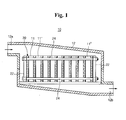
- Fig. 1 is a schematic cross sectional side view of a secondary battery module according to one embodiment of the present invention.
- Fig. 2 is a perspective view of a barrier rib according to a first embodiment of the present invention.
- Fig. 3 is a perspective view illustrating another array of protrusions of the barrier rib according to the fist embodiment of the present invention.
- Fig. 4 is a partial cross sectional view of the secondary battery module having the barrier rib according to the fist embodiment of the present invention.
- Figs. 5A, 5B , 6A, 6B , 6C, 7A , 7B and 7C are partial cross sectional views of secondary battery modules according to modified examples of the first embodiment of the present invention.
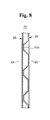
- Fig. 8 is a partial cross sectional view of a secondary battery module having a barrier rib according to a second embodiment of the present invention.
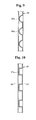
- Figs. 9, 10 and 11 are partial cross sectional views of secondary battery modules according to first modified examples of the second embodiment of the present invention.
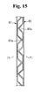
- Figs. 12 , 13 , 14 and 15 are partial cross sectional views of secondary battery modules according to second modified examples of the second embodiment of the present invention.
- Figs. 16, 17 , 18 and 19 are partial cross sectional views of secondary battery modules according to third modified examples of the second embodiment of the present invention.
- Fig. 20 is a drawing illustrating the function of the barrier ribs according to the first embodiment of the present invention.
- a secondary battery module 10 includes a plurality of unit batteries 11, 11 1 ??11 n spaced apart from each other at a predetermined distance.
- the unit battery 11 is a square type secondary battery, which, as a general secondary battery, includes a container, an electrode assembly including a positive electrode, a negative electrode, and a separator to be inserted to the container, and a cap assembly disposed in the container.
- Barrier ribs 20 are disposed between the unit batteries 11, 11 1 ?? 11 n to flow cooling medium (e.g., air in the present embodiment) between the unit batteries 11, 11 1 ?? 11 n , and to be connected to the unit batteries 11, 11 1 ?? 11 n and support them.
- flow cooling medium e.g., air in the present embodiment
- Such unit batteries 11, 11 1 ?? 11 n and barrier ribs 20 are fixed in place by fastening plates 22 and fastening rods 24 to form an assembly.
- the assembly is mounted in a housing 12 having an inlet 12a receiving air and an outlet 12b discharging the air which cools the unit batteries 11.
- a housing 12 having an inlet 12a receiving air and an outlet 12b discharging the air which cools the unit batteries 11.
- Such a housing could form part of a power / air flow system of a motor drive of machine systems, including hybrid electric vehicles.
- the inlet 12a is disposed in one side of the upper portion of the housing 12, and the outlet 12b is disposed in one side of the lower portion of the housing 12a being opposite to the inlet 12a.
- the structure of the housing 12a is only one example of the secondary battery modules that the present invention can adopt, and is not limited thereto.
- Such a secondary battery module 10 enables the air incoming inside the housing 12 through the inlet 12a of the housing 12 to flow from the upper portion to the lower portion of the housing 12 and to exit outside the housing 12 through the outlet 12b of the housing 12.
- the air passes through the barrier ribs 20, and heat generated from the unit batteries 11, 11 1 ?? 11 n are heat-exchanged by the air, which can cool them.
- a barrier rib 20 of the secondary battery module 10 includes a plate shaped base 20a with a size corresponding to the size of the side surface of a unit battery 11 and having a plurality of protrusions 20b formed on the base 20a.
- the protrusions 20b are protruded from one surface of the base 20a, and spaced apart from each other at a predetermined distance.
- the protrusions 20b may be formed in a vertically or horizontally staggered array, or in a lattice array 20' as shown in Fig. 3 .
- the protrusions 20b protrude from the base 20a as a solid protrusion, or they may protrude from the base 20a having a hollowed-out inside groove 20c as shown in Fig. 4 . In the following embodiments, the protrusions have the latter type of protrusion.
- the protrusions 20b of the present embodiment have a conical shape with a cutaway apex area that is wide at the top and narrow at the bottom.
- the barrier rib 20 When the barrier rib 20 is disposed between the unit batteries 11, 11 1 ?? 11 n to form an assembly, the front ends of the protrusions 20b are closely contacted with the side surface of one unit battery 11, and the side surface of the base 20a is closely contacted with the side surface of the other unit battery 11 1 .
- Such an arrangement of the barrier rib 20 is applied to all the barrier ribs 20 disposed between the unit batteries 11, 11 1 ?? 11 n .
- the above arrangement enables the distances between the unit batteries 11, 11 1 ?? 11 n to be maintained at a predetermined size, and the heat generated from the unit batteries 11, 11 1 ?? 11 n may be cooled by the air passing through the space formed between the protrusions 20b.
- the protrusions 20b of the present embodiment have a conical shape with a cutaway apex area that is wide at the top and narrow at the bottom. That is, they have a shape with an inclined plane 200b inclined at a predetermined angel ( ⁇ ) with respect to one surface of the barrier rib 20, i.e. one surface of the base 20a ( Fig. 4 ).
- the angle ( ⁇ ) is set considering the strength characteristic of the protrusions 20b. That is, if the unit battery is under an abnormal condition and the internal pressure of the unit battery is increased to force compressive stress to the protrusions 20b, the protrusions 20b should have strength enough to endure the stress. Otherwise, the barrier rib 20 cannot support the unit battery firmly and accordingly, the safety vent for safety of the unit battery is not broken at a predetermined pressure value but is broken at a higher pressure value, which causes the unstable operation. Therefore, the whole battery module may be put into a dangerous condition.
- the angle ( ⁇ ) meets the following formula to allow the protrusions 20b to have enough strength: 45 ⁇ ° ⁇ ⁇ ⁇ 90 ⁇ °
- the angle ( ⁇ ) would meet the following formula: 50 ⁇ ° ⁇ ⁇ ⁇ 70 ⁇ °
- the angle ( ⁇ ) would meet the following formula: 55 ⁇ ° ⁇ ⁇ ⁇ 65 ⁇ °
- the below Table 1 shows the strength and the cooling efficiency of the barrier ribs of examples according to the present invention.
- the lower of the compressive pressure means the higher of the strength.
- the volume efficiency is defined as the volume ratio of protrusions to flowing space of cooling medium (volume of protrusions in flowing space/flowing space), and the higher of the volume efficiency means the higher of the cooling efficiency.
- the barrier ribs of examples according to the present invention in Table 1 below have protrusions with an angle ( ⁇ ) of 60° or 90°.
- the barrier ribs of the present examples were formed by press process or injection process, and are made of aluminum (AL3003).
- Example 1 ( ⁇ 60°) 58.19 29.16 89
- Example 2 ( ⁇ 90°) 61.12 33.71 86
- the angle is greater than 90°, the shape of the protrusions is restricted so it is difficult to form the protrusions. If the angle is less than 45°, the strength of the protrusions is lowered so they can be easily broken.
- Figs. 5A to 7C shows modified examples of the first embodiment of the present invention, and these modified examples have various shapes of protrusions.
- a protrusion 30b formed on a base 30a in a barrier rib 30 has a hemisphere shape.
- a protrusion 40b formed on a base 40a in a barrier rib 40 has a shape of a cylinder ( Fig. 6B ) or prism such as a rectangular prism ( Fig. 6C ).
- the inclined plane of the prism may be formed to meet the above angle ( ⁇ ).
- a protrusion 50b formed on a base 50a in a barrier rib 50 has a shape of a cone ( Fig. 7B ) or pyramid such as a quadrangular pyramid ( Fig. 7C ).
- the inclined plane of the cone or pyramid may be formed to meet the above angle ( ⁇ ).
- Figs. 8 to 11 are cross sectional views of a secondary battery module according to a second embodiment of the present invention.
- the secondary battery module 60 according to the second embodiment basically has a similar overall structure as that of the first embodiment, except that it further includes another barrier rib, i.e., an auxiliary barrier rib 65 disposed between a unit battery 61 and a unit battery 61 1 together with a barrier rib 63 much like the barrier rib of the previous embodiment.
- another barrier rib i.e., an auxiliary barrier rib 65 disposed between a unit battery 61 and a unit battery 61 1 together with a barrier rib 63 much like the barrier rib of the previous embodiment.
- the auxiliary barrier rib 65 may have a size corresponding to the size of the barrier rib 63 and its entire surface may be flat. Its thickness and material may be the same as those of the barrier rib 63.
- the battery module 60 of the second embodiment is different from that of the first embodiment in that the auxiliary barrier rib 65 contacts with the side surface of the unit battery 61 rather than the protrusions 63a of the barrier rib 63. Accordingly, the contact area with the unit battery 61 is increased and thereby the emission of heat generated from the unit battery 61 is more efficient. Also, it can prevent the protrusions 63a from distorting the side surface of the unit battery 61.
- Figs. 9 to 11 show secondary battery modules according to first examples of the second embodiment in which the basic structure is the same as that of Fig. 8 , but the protrusions formed on the barrier rib have different shapes.
- a protrusion 66a of a barrier rib 66 has a hemisphere shape.
- a protrusion 67a of a barrier rib 67 has a shape of a cylinder or prism.
- a protrusion 69a of a barrier rib 69 has a shape of a cone or pyramid.
- Figs. 12 to 15 show cross sectional views illustrating the structure of secondary battery modules according to second modified examples of the second embodiment of the present invention.
- the secondary battery module 70 has a barrier rib 73 and an auxiliary barrier rib 75 disposed between a unit battery 71 and a unit battery 71 1 much like the above second embodiment.
- the auxiliary barrier rib 75 does not have the structure that the entire surface is flat like the auxiliary barrier rib of the second embodiment, but has the structure that a plurality of protrusions 75b are formed on its base 75a much like the barrier rib 73. That is, in the second modified examples, the auxiliary barrier rib 75 has a plurality of the protrusions 75b as well as the barrier rib 73 has a plurality of the protrusions 73b on the base 73a.
- the protrusions 73b and 75b have the same shape as those described in the first embodiment.
- barrier rib 73 and the auxiliary barrier rib 75 are disposed between the unit batteries 71 and 71 1 , barrier rib 73 contacts unit battery 71 1 and auxiliary barrier rib 75 contacts unit battery 71.
- the protrusions 73b and 75b are disposed not to overlap each other. That is, the protrusions 73 b of the barrier rib 73 are in contact with the base 75a of the auxiliary barrier rib 75, and the protrusions 75b of the auxiliary barrier rib 75 are in contact with the base 73a of the barrier rib 73, and thereby the barrier rib 73 the auxiliary barrier rib 75 are, in essence, combined with each other.
- Such an arrangement of the barrier rib 73 and the auxiliary barrier rib 75 can increase the strength of the barrier rib 73 and the auxiliary barrier rib 75 due to a staggered array of the protrusions 73b and 75b, and therefore, can more stably support the unit batteries 71 and 71 1 .
- Figs. 13 to 14 show the secondary battery module in which the basic structure is the same as that of Fig. 12 , but the protrusions formed on the barrier rib and the auxiliary barrier rib have different shapes.
- a protrusion 77a of a barrier rib 77 and a protrusion 79a of an auxiliary barrier rib 79 have a hemisphere shape.
- a protrusion 81a of a barrier rib 81 and a protrusion 83a of an auxiliary barrier rib 83 have a shape of a cylinder or prism.
- a protrusion 85a of a barrier rib 85 and a protrusion 87a of an auxiliary barrier rib 87 have a shape of a cone or pyramid.
- Figs. 16 to 19 show cross sectional views illustrating the structure of secondary battery modules according to third modified examples of the second embodiment of the present invention.
- both of a barrier rib 89 and an auxiliary barrier rib 91 have protrusions 89a and 91 a much like the first modified example, except that these protrusions 89a and 91 a are disposed between and contact unit batteries 93 and 93 1 .
- Such an arrangement of the barrier rib 89 and the auxiliary barrier rib 91 can increase the strength of the barrier rib 89 and the auxiliary barrier rib 91 due to the protrusions 89a and 91 a, and therefore, can support the unit batteries 93 and 93 1 more stably, much like the first modified example. In addition, it can expand the air flow channel formed between the protrusions 89a and 91 a to enhance the cooling efficiency for the unit batteries 93 and 93 1 .
- Figs. 17 to 19 show the secondary battery module in which the basic structure is similar to that of Fig. 16 , but the protrusions formed on the barrier rib and the auxiliary barrier rib have different shapes.
- a protrusion 95a of a barrier rib 95 and a protrusion 97a of an auxiliary barrier rib 97 have a hemisphere shape.
- a protrusion 99a of a barrier rib 99 and a protrusion 101 a of an auxiliary barrier rib 101 have a shape of a cylinder or prism.
- a protrusion 103a of a barrier rib 103 and a protrusion 105a of an auxiliary barrier rib 105 have the shape of a cone or pyramid.
- Fig. 20 when the protrusions of the barrier rib are disposed on the base, these protrusions may be formed to meet the following formulas.
- the angle ( ⁇ ) meets the following formula: 30 ⁇ ° ⁇ ⁇ ⁇ 150 ⁇ °
- angle ( ⁇ ) can meet the following formula: 45 ⁇ ° ⁇ ⁇ ⁇ 60 ⁇ °
- the air passing through the barrier rib 20 is dispersed at all protrusions of the barrier rib 20 so it changes its progress path to float. Then, the speed of air flow may be a factor which influences the cooling efficiency of the unit battery.
- the present embodiment allows the air to have a proper flow speed by maintaining the angle ( ⁇ ) within the above range to maximize the cooling efficiency for the unit battery.
- the secondary battery module of in accordance with the present invention is provided with sufficient strength as a result of the barrier ribs, and because the barrier ribs have the protrusions, it enables the unit batteries to be efficiently cooled as well as preventing the distortion of the unit batteries.
- the secondary battery module may be effectively used for motor driving machines such as the hybrid electric vehicles, electric vehicles, motor scooters, motorbikes, or electric vacuum cleaners requiring high power.
- barrier ribs described above are made of the aluminum, they may be made of insulating material, such as plastics, as well as metals, such as aluminum.
Landscapes
- Engineering & Computer Science (AREA)
- Chemical Kinetics & Catalysis (AREA)
- Electrochemistry (AREA)
- General Chemical & Material Sciences (AREA)
- Chemical & Material Sciences (AREA)
- Manufacturing & Machinery (AREA)
- General Physics & Mathematics (AREA)
- Pure & Applied Mathematics (AREA)
- Sustainable Development (AREA)
- Sustainable Energy (AREA)
- Power Engineering (AREA)
- Transportation (AREA)
- Mechanical Engineering (AREA)
- Physics & Mathematics (AREA)
- Algebra (AREA)
- Life Sciences & Earth Sciences (AREA)
- Mathematical Analysis (AREA)
- Mathematical Optimization (AREA)
- Automation & Control Theory (AREA)
- Secondary Cells (AREA)
- Battery Mounting, Suspending (AREA)
- Sealing Battery Cases Or Jackets (AREA)
- Hybrid Cells (AREA)
Abstract
Description
- The present invention relates to a secondary battery, and more particularly, to a secondary battery module having a plurality of unit batteries and a barrier rib for the secondary battery module.
- Unlike a primary battery, the secondary battery may be recharged. Lower power batteries are used for various portable electronic devices such as cellular phones, laptop computers, and camcorders. Bulk size batteries are used as the power source for motor drive, such as in hybrid electric vehicles. Examples of secondary battery modules include
JP 2003 007355 US 6,475,659 B1 ,US 6,051,328 ,JP 2001 023702 EP 1 139 483 A1 . - Depending on the external shape, secondary batteries may be classified into different types, for example, square and cylindrical batteries. When they are used for motor drive of the machines requiring a high power source such as the hybrid electric vehicles, the secondary batteries may form a secondary battery module of high power.
- The secondary battery module is formed by serially connecting several secondary batteries (hereinafter "unit battery"), and each of the unit batteries includes an electrode assembly in which a separator is interposed between a positive electrode and a negative electrode. The electrode assembly is inserted inside a container, and a cap assembly is assembled with the container to seal the container. The cap assembly includes terminals disposed extending from the inside to the outside of the container and are electrically connected to a positive electrode and a negative electrode, respectively.
- In addition, if the unit batteries are square type batteries, the unit batteries are arranged to alternate positive and negative terminals of one unit battery projected from the upper portion of the cap assembly with the positive and negative terminals of an adjacent unit battery. Adaptors of the electric conductor are typically mounted on threaded negative and positive terminals such that they are electrically connected with each other to form the battery module.
- Since the battery module connects several to tens of unit batteries to form one battery module, there is a need to efficiently emit heat generated from each unit battery. In particular, when the unit battery is used as bulk size secondary batteries for motor drive such as in electric vehicles, hybrid electric vehicles, motor scooters, and vacuum cleaners, the heat emission is of significant importance.
- If the heat emission does not occur properly, the temperature of the battery module may excessively increase due to the heat generated from each unit battery, and accordingly, not only the battery module but also the machines with the battery module, can malfunction.
- Accordingly, when forming the battery module, a barrier rib is disposed between unit batteries, and the space between unit batteries formed by the barrier rib is used not only for cooling unit batteries but also for preventing distortion due to heat expansion of the unit batteries.
- To perform such functions, the barrier rib needs sufficient strength and structure for efficient heat emission.
- However, barrier ribs in the conventional secondary battery module do not satisfy the above two conditions simultaneously so there is difficulty in forming secondary battery modules of the quality which consumers expect.
- That is, if the barrier ribs ensure the sufficient strength, its manufacturing cost is increased and there is restriction in designing a passage of cooling air. Alternatively, if the barrier ribs are formed having high cooling efficiency, they tend to exhibit structural weakness.
- In accordance with the present invention a secondary battery module is provided in which a barrier rib not only has structural strength enough to maintain the shape of a unit battery but also efficiently controls the temperature of a unit battery.
- According to one aspect of the present invention, a secondary battery module includes a plurality of unit batteries adjacently spaced apart from each other, and a barrier rib disposed between adjacent unit batteries, the barrier rib having a plurality of protrusions, wherein the protrusions have a shape with an inclined plane inclined at a predetermined angle α with respect to one surface of the barrier rib and the predetermined angle α meets 45° ≤ α ≤ 90°.
- The barrier rib may have a plate shaped base, and a plurality of the protrusions may be formed on the base.
- The plurality of the protrusions may be disposed on one surface of the base.
- The protrusion may have a conical or pyramid shape.
- The secondary battery module may further include an auxiliary barrier rib disposed between the barrier rib and the unit battery.
- The auxiliary barrier rib may have a plate shaped base having a flat surface.
- The auxiliary barrier rib may have a plate shaped base, and a plurality of protrusions formed on the base.
- The barrier rib and the auxiliary barrier rib may be in contact with each other and disposed between the unit batteries.
- The protrusion of the barrier rib may be in contact with the base of the auxiliary barrier rib, and the protrusion of the auxiliary barrier rib may be in contact with the base of the barrier rib.
- The protrusion of the barrier rib is contacted with the protrusion of the auxiliary barrier rib.
- The protrusion may have a shape with an inclined plane inclined at a predetermined angle with respect to one surface of the barrier rib.
- The protrusions are formed in a staggered array on the base, and the secondary battery module may meet the following formula:

where β is, with respect to one protrusion disposed in a column, an angle between other protrusions which are adjacent to the one protrusion and disposed in other directions intersecting the one protrusion. - The protrusion may be formed in a lattice array on the base.
- The secondary battery module may include a housing mounting the plurality of unit batteries and barrier ribs and having a cooling medium input and output adapted for use in a motor driven device.
-
Fig. 1 is a schematic cross sectional side view of a secondary battery module according to one embodiment of the present invention. -
Fig. 2 is a perspective view of a barrier rib according to a first embodiment of the present invention. -
Fig. 3 is a perspective view illustrating another array of protrusions of the barrier rib according to the fist embodiment of the present invention. -
Fig. 4 is a partial cross sectional view of the secondary battery module having the barrier rib according to the fist embodiment of the present invention. -
Figs. 5A, 5B ,6A, 6B ,6C, 7A ,7B and 7C are partial cross sectional views of secondary battery modules according to modified examples of the first embodiment of the present invention. -
Fig. 8 is a partial cross sectional view of a secondary battery module having a barrier rib according to a second embodiment of the present invention. -
Figs. 9, 10 and11 are partial cross sectional views of secondary battery modules according to first modified examples of the second embodiment of the present invention. -
Figs. 12 ,13 ,14 and15 are partial cross sectional views of secondary battery modules according to second modified examples of the second embodiment of the present invention. -
Figs. 16, 17 ,18 and19 are partial cross sectional views of secondary battery modules according to third modified examples of the second embodiment of the present invention. -
Fig. 20 is a drawing illustrating the function of the barrier ribs according to the first embodiment of the present invention. - Referring to
Fig. 1 , asecondary battery module 10 according to the present embodiment includes a plurality ofunit batteries - The
unit battery 11 according to the present embodiment is a square type secondary battery, which, as a general secondary battery, includes a container, an electrode assembly including a positive electrode, a negative electrode, and a separator to be inserted to the container, and a cap assembly disposed in the container. -
Barrier ribs 20 are disposed between theunit batteries unit batteries unit batteries -
Such unit batteries barrier ribs 20 are fixed in place byfastening plates 22 and fasteningrods 24 to form an assembly. - The assembly is mounted in a
housing 12 having aninlet 12a receiving air and anoutlet 12b discharging the air which cools theunit batteries 11. Such a housing could form part of a power / air flow system of a motor drive of machine systems, including hybrid electric vehicles. - The
inlet 12a is disposed in one side of the upper portion of thehousing 12, and theoutlet 12b is disposed in one side of the lower portion of thehousing 12a being opposite to theinlet 12a. However, the structure of thehousing 12a is only one example of the secondary battery modules that the present invention can adopt, and is not limited thereto. - Such a
secondary battery module 10 enables the air incoming inside thehousing 12 through theinlet 12a of thehousing 12 to flow from the upper portion to the lower portion of thehousing 12 and to exit outside thehousing 12 through theoutlet 12b of thehousing 12. - During this process, the air passes through the
barrier ribs 20, and heat generated from theunit batteries - In the following, the details of
secondary battery module 10 having the above function will be described. - Now referring to
Fig. 2 , abarrier rib 20 of thesecondary battery module 10 includes a plateshaped base 20a with a size corresponding to the size of the side surface of aunit battery 11 and having a plurality ofprotrusions 20b formed on thebase 20a. Theprotrusions 20b are protruded from one surface of thebase 20a, and spaced apart from each other at a predetermined distance. - The
protrusions 20b may be formed in a vertically or horizontally staggered array, or in a lattice array 20' as shown inFig. 3 . - In addition, the
protrusions 20b protrude from thebase 20a as a solid protrusion, or they may protrude from thebase 20a having a hollowed-out insidegroove 20c as shown inFig. 4 . In the following embodiments, the protrusions have the latter type of protrusion. - The
protrusions 20b of the present embodiment have a conical shape with a cutaway apex area that is wide at the top and narrow at the bottom. - When the
barrier rib 20 is disposed between theunit batteries protrusions 20b are closely contacted with the side surface of oneunit battery 11, and the side surface of thebase 20a is closely contacted with the side surface of theother unit battery 111. - Such an arrangement of the
barrier rib 20 is applied to all thebarrier ribs 20 disposed between theunit batteries - The above arrangement enables the distances between the
unit batteries unit batteries protrusions 20b. - The
protrusions 20b of the present embodiment have a conical shape with a cutaway apex area that is wide at the top and narrow at the bottom. That is, they have a shape with aninclined plane 200b inclined at a predetermined angel (α) with respect to one surface of thebarrier rib 20, i.e. one surface of thebase 20a (Fig. 4 ). - The angle (α) is set considering the strength characteristic of the
protrusions 20b. That is, if the unit battery is under an abnormal condition and the internal pressure of the unit battery is increased to force compressive stress to theprotrusions 20b, theprotrusions 20b should have strength enough to endure the stress. Otherwise, thebarrier rib 20 cannot support the unit battery firmly and accordingly, the safety vent for safety of the unit battery is not broken at a predetermined pressure value but is broken at a higher pressure value, which causes the unstable operation. Therefore, the whole battery module may be put into a dangerous condition. - Considering such a problem, the angle (α) meets the following formula to allow the
protrusions 20b to have enough strength:
- In one exemplary embodiment the angle (α) would meet the following formula:

- In another exemplary embodiment, the angle (α) would meet the following formula:

- The below Table 1 shows the strength and the cooling efficiency of the barrier ribs of examples according to the present invention. In the Table 1, the lower of the compressive pressure means the higher of the strength. The volume efficiency is defined as the volume ratio of protrusions to flowing space of cooling medium (volume of protrusions in flowing space/flowing space), and the higher of the volume efficiency means the higher of the cooling efficiency.
- The barrier ribs of examples according to the present invention in Table 1 below have protrusions with an angle (α) of 60° or 90°. The barrier ribs of the present examples were formed by press process or injection process, and are made of aluminum (AL3003).
Table 1 Press Process Injection Process Compressive Pressure (Mpa) Compressive Pressure (Mpa) Volume efficiency (%) Example 1 (α = 60°) 58.19 29.16 89 Example 2 (α = 90°) 61.12 33.71 86 - If the angle is greater than 90°, the shape of the protrusions is restricted so it is difficult to form the protrusions. If the angle is less than 45°, the strength of the protrusions is lowered so they can be easily broken.
-
Figs. 5A to 7C shows modified examples of the first embodiment of the present invention, and these modified examples have various shapes of protrusions. - In
Figs. 5A to 5B , aprotrusion 30b formed on abase 30a in abarrier rib 30 has a hemisphere shape. - In
Figs. 6A to 6C , aprotrusion 40b formed on abase 40a in abarrier rib 40 has a shape of a cylinder (Fig. 6B ) or prism such as a rectangular prism (Fig. 6C ). The inclined plane of the prism may be formed to meet the above angle (α). - In
Figs. 7A to 7C , aprotrusion 50b formed on abase 50a in abarrier rib 50 has a shape of a cone (Fig. 7B ) or pyramid such as a quadrangular pyramid (Fig. 7C ). The inclined plane of the cone or pyramid may be formed to meet the above angle (α). -
Figs. 8 to 11 are cross sectional views of a secondary battery module according to a second embodiment of the present invention. Thesecondary battery module 60 according to the second embodiment basically has a similar overall structure as that of the first embodiment, except that it further includes another barrier rib, i.e., anauxiliary barrier rib 65 disposed between aunit battery 61 and aunit battery 611 together with abarrier rib 63 much like the barrier rib of the previous embodiment. - The
auxiliary barrier rib 65 may have a size corresponding to the size of thebarrier rib 63 and its entire surface may be flat. Its thickness and material may be the same as those of thebarrier rib 63. - The
battery module 60 of the second embodiment is different from that of the first embodiment in that theauxiliary barrier rib 65 contacts with the side surface of theunit battery 61 rather than theprotrusions 63a of thebarrier rib 63. Accordingly, the contact area with theunit battery 61 is increased and thereby the emission of heat generated from theunit battery 61 is more efficient. Also, it can prevent theprotrusions 63a from distorting the side surface of theunit battery 61. -
Figs. 9 to 11 show secondary battery modules according to first examples of the second embodiment in which the basic structure is the same as that ofFig. 8 , but the protrusions formed on the barrier rib have different shapes. - In
Fig. 9 , aprotrusion 66a of abarrier rib 66 has a hemisphere shape. InFig. 10 , aprotrusion 67a of abarrier rib 67 has a shape of a cylinder or prism. InFig. 11 , aprotrusion 69a of abarrier rib 69 has a shape of a cone or pyramid. -
Figs. 12 to 15 show cross sectional views illustrating the structure of secondary battery modules according to second modified examples of the second embodiment of the present invention. - With reference now to
Fig. 12 , thesecondary battery module 70 has abarrier rib 73 and anauxiliary barrier rib 75 disposed between aunit battery 71 and aunit battery 711 much like the above second embodiment. However, theauxiliary barrier rib 75 does not have the structure that the entire surface is flat like the auxiliary barrier rib of the second embodiment, but has the structure that a plurality ofprotrusions 75b are formed on itsbase 75a much like thebarrier rib 73. That is, in the second modified examples, theauxiliary barrier rib 75 has a plurality of theprotrusions 75b as well as thebarrier rib 73 has a plurality of theprotrusions 73b on thebase 73a. - The
protrusions - When the
barrier rib 73 and theauxiliary barrier rib 75 are disposed between theunit batteries barrier rib 73contacts unit battery 711 andauxiliary barrier rib 75contacts unit battery 71. In the second modified examples, theprotrusions protrusions 73 b of thebarrier rib 73 are in contact with thebase 75a of theauxiliary barrier rib 75, and theprotrusions 75b of theauxiliary barrier rib 75 are in contact with thebase 73a of thebarrier rib 73, and thereby thebarrier rib 73 theauxiliary barrier rib 75 are, in essence, combined with each other. - Such an arrangement of the
barrier rib 73 and theauxiliary barrier rib 75 can increase the strength of thebarrier rib 73 and theauxiliary barrier rib 75 due to a staggered array of theprotrusions unit batteries -
Figs. 13 to 14 show the secondary battery module in which the basic structure is the same as that ofFig. 12 , but the protrusions formed on the barrier rib and the auxiliary barrier rib have different shapes. - In
Fig. 13 , aprotrusion 77a of abarrier rib 77 and aprotrusion 79a of anauxiliary barrier rib 79 have a hemisphere shape. InFig. 14 , aprotrusion 81a of abarrier rib 81 and aprotrusion 83a of anauxiliary barrier rib 83 have a shape of a cylinder or prism. InFig. 15 , aprotrusion 85a of abarrier rib 85 and aprotrusion 87a of anauxiliary barrier rib 87 have a shape of a cone or pyramid. -
Figs. 16 to 19 show cross sectional views illustrating the structure of secondary battery modules according to third modified examples of the second embodiment of the present invention. - With reference to
Fig. 16 , in the third modified example both of abarrier rib 89 and anauxiliary barrier rib 91 haveprotrusions protrusions contact unit batteries - Such an arrangement of the
barrier rib 89 and theauxiliary barrier rib 91 can increase the strength of thebarrier rib 89 and theauxiliary barrier rib 91 due to theprotrusions unit batteries protrusions unit batteries -
Figs. 17 to 19 show the secondary battery module in which the basic structure is similar to that ofFig. 16 , but the protrusions formed on the barrier rib and the auxiliary barrier rib have different shapes. - In
Fig. 17 , aprotrusion 95a of abarrier rib 95 and aprotrusion 97a of anauxiliary barrier rib 97 have a hemisphere shape. InFig. 18 , aprotrusion 99a of abarrier rib 99 and a protrusion 101 a of anauxiliary barrier rib 101 have a shape of a cylinder or prism. InFig. 19 , aprotrusion 103a of abarrier rib 103 and aprotrusion 105a of anauxiliary barrier rib 105 have the shape of a cone or pyramid. - Referring now to
Fig. 20 , and described with respect to the barrier rib shown inFig. 2 for the convenience, when the protrusions of the barrier rib are disposed on the base, these protrusions may be formed to meet the following formulas. When theprotrusions base 20a, the angle (β) meets the following formula:
- ii) where β is, with respect to one
protrusion 20b disposed in a column, an angle betweenother protrusions 20b' and 20b" which are adjacent to the oneprotrusion 20b and disposed in other directions intersecting the oneprotrusion 20b. - In addition, the angle (β) can meet the following formula:

- If the air flows into the
barrier rib 20 through theinlet 12a of thehousing 12 to contact oneprotrusion 20b' of thebarrier rib 20 by such an arrangement of theprotrusions protrusion 20b' (Arrows 1 and 2 inFig. 20 ). - In such a way, the air passing through the
barrier rib 20 is dispersed at all protrusions of thebarrier rib 20 so it changes its progress path to float. Then, the speed of air flow may be a factor which influences the cooling efficiency of the unit battery. - That is, if the air does not have a proper speed, when the air passes through the
barrier rib 20, it is not effectively dispersed within thebarrier rib 20 so the heat exchange does not occur. This causes the decrease of the cooling efficiency of the unit battery. - Furthermore, if the air does not have a proper speed, pressure drop within the
barrier rib 20 is increased to thereby increase the resistance to the air flow passing through thehousing 12. This increases the load of the apparatus providing air to thehousing 12 for increasing a flow speed, for example, a cooling fan, as well as decreases the cooling efficiency of the unit battery, which causes another problem. - Considering these points, the present embodiment allows the air to have a proper flow speed by maintaining the angle (β) within the above range to maximize the cooling efficiency for the unit battery.
- Continuous experiments have been carried out which indicate that if the angle (β) is less than 30°, the heat exchange efficiency becomes too low, and if the angle (β) is more than 150°, the flow speed of the air becomes too low to satisfy the cooling efficiency of the unit battery.
- The secondary battery module of in accordance with the present invention is provided with sufficient strength as a result of the barrier ribs, and because the barrier ribs have the protrusions, it enables the unit batteries to be efficiently cooled as well as preventing the distortion of the unit batteries.
- The secondary battery module may be effectively used for motor driving machines such as the hybrid electric vehicles, electric vehicles, motor scooters, motorbikes, or electric vacuum cleaners requiring high power.
- Although the barrier ribs described above are made of the aluminum, they may be made of insulating material, such as plastics, as well as metals, such as aluminum.
-
Claims (9)
- A secondary battery module comprising:a plurality of unit batteries adjacently spaced apart from each other; anda barrier rib disposed between adjacent unit batteries, the barrier rib having a plate shaped base with a plurality of protrusions thereon,wherein the protrusions have a shape with an inclined plane inclined at a predetermined angle α with respect to one surface of the barrier rib andthe predetermined angle α meets 45° ≤ α ≤90°,characterized in that
the protrusions are formed in a staggered array on the plate shaped base in such a way that the secondary battery module meets the following formula:
where β is, with respect to one protrusion disposed in a first column, an angle between other protrusions which are adjacent to the one protrusion and disposed in other directions intersecting the one protrusion. - The secondary battery module of claim 1, wherein the plurality of protrusions is disposed on one surface of the plate shaped base.
- The secondary battery module of claim 1, wherein a protrusion has a conical shape.
- The secondary battery module of claim 3, wherein the protrusion has a conical shape with a cutaway apex area.
- The secondary battery module of claim 1, wherein the secondary battery module meets the following formula:

where α is the predetermined angle. - The secondary battery module of claim 5, wherein the secondary battery module meets the following formula:

where α is the predetermined angle. - The secondary battery module of claim 1, wherein the protrusions are formed in a lattice array on the base.
- The secondary battery module of claim 1, wherein the unit batteries are square shape batteries.
- The secondary battery module of claim 1, wherein the secondary battery module includes a housing mounting the plurality of unit batteries and having a cooling medium input and output adapted for use in a motor driven device.
Applications Claiming Priority (2)
| Application Number | Priority Date | Filing Date | Title |
|---|---|---|---|
| KR2004048155 | 2004-06-25 | ||
| KR1020040048155A KR100627335B1 (en) | 2004-06-25 | 2004-06-25 | Battery Modules and Battery Modules |
Publications (2)
| Publication Number | Publication Date |
|---|---|
| EP1610407A1 EP1610407A1 (en) | 2005-12-28 |
| EP1610407B1 true EP1610407B1 (en) | 2011-03-16 |
Family
ID=34940237
Family Applications (1)
| Application Number | Title | Priority Date | Filing Date |
|---|---|---|---|
| EP20050105702 Expired - Lifetime EP1610407B1 (en) | 2004-06-25 | 2005-06-27 | Secondary battery module |
Country Status (7)
| Country | Link |
|---|---|
| US (1) | US7682732B2 (en) |
| EP (1) | EP1610407B1 (en) |
| JP (1) | JP2006012847A (en) |
| KR (1) | KR100627335B1 (en) |
| CN (1) | CN100367538C (en) |
| AT (1) | ATE502413T1 (en) |
| DE (1) | DE602005026886D1 (en) |
Cited By (1)
| Publication number | Priority date | Publication date | Assignee | Title |
|---|---|---|---|---|
| EP3963645A1 (en) * | 2019-05-02 | 2022-03-09 | Oerlikon Friction Systems (Germany) GmbH | Pressure module, in particular for lithium-ion battery cells |
Families Citing this family (95)
| Publication number | Priority date | Publication date | Assignee | Title |
|---|---|---|---|---|
| KR100669414B1 (en) * | 2004-11-30 | 2007-01-15 | 삼성에스디아이 주식회사 | Battery Modules and Battery Modules |
| US7601458B2 (en) | 2005-03-24 | 2009-10-13 | Samsung Sdi Co., Ltd. | Rechargeable battery and battery module |
| KR100684758B1 (en) * | 2005-05-16 | 2007-02-20 | 삼성에스디아이 주식회사 | Secondary battery module |
| KR20070013455A (en) * | 2005-07-26 | 2007-01-31 | 삼성에스디아이 주식회사 | Secondary battery module |
| KR100684766B1 (en) * | 2005-07-29 | 2007-02-20 | 삼성에스디아이 주식회사 | Secondary battery module |
| KR100684769B1 (en) * | 2005-07-29 | 2007-02-20 | 삼성에스디아이 주식회사 | Secondary battery module |
| KR101029021B1 (en) * | 2005-12-02 | 2011-04-14 | 주식회사 엘지화학 | High Cooling Battery Module |
| KR101212369B1 (en) * | 2006-01-05 | 2012-12-13 | 에스케이이노베이션 주식회사 | Cooling structure of lithium ion secondary battery system |
| SE530190C2 (en) * | 2006-01-17 | 2008-03-25 | Nilar Int Ab | A battery stack arrangement |
| KR100740126B1 (en) * | 2006-02-02 | 2007-07-16 | 삼성에스디아이 주식회사 | Partition wall for a secondary battery module and a secondary battery module including the same |
| KR100948003B1 (en) * | 2006-02-27 | 2010-03-18 | 주식회사 엘지화학 | Medium and large battery packs with excellent cooling efficiency |
| KR100805114B1 (en) * | 2006-04-25 | 2008-02-21 | 삼성에스디아이 주식회사 | Secondary battery module |
| KR100805153B1 (en) * | 2006-04-25 | 2008-02-21 | 삼성에스디아이 주식회사 | Battery module |
| JP4839955B2 (en) * | 2006-05-11 | 2011-12-21 | トヨタ自動車株式会社 | Battery pack and vehicle |
| KR101256074B1 (en) * | 2006-07-26 | 2013-04-18 | 삼성에스디아이 주식회사 | Battery module having spacer |
| JP5122194B2 (en) * | 2007-07-09 | 2013-01-16 | 小島プレス工業株式会社 | Cooling system |
| JP5334420B2 (en) * | 2008-01-16 | 2013-11-06 | 三洋電機株式会社 | Battery system |
| JP5305837B2 (en) * | 2008-10-30 | 2013-10-02 | 株式会社東芝 | Battery module |
| KR20110024954A (en) * | 2009-09-03 | 2011-03-09 | 삼성전자주식회사 | Secondary Battery Module with Cooling Channel |
| DE102009044997A1 (en) * | 2009-09-25 | 2011-03-31 | SB LiMotive Company Ltd., Suwon | Thermal decoupling of neighboring cells in a battery system |
| US8268472B2 (en) | 2009-09-30 | 2012-09-18 | Bright Automotive, Inc. | Battery cooling apparatus for electric vehicle |
| KR101122900B1 (en) * | 2009-11-17 | 2012-03-21 | 삼성에스디아이 주식회사 | Case for Secondary Battery and Lithium Secondary Battery Using the Same |
| EP2348557B1 (en) | 2010-01-13 | 2013-07-03 | Samsung SDI Co., Ltd. | Secondary battery |
| KR101182958B1 (en) * | 2010-02-01 | 2012-09-18 | 에스비리모티브 주식회사 | Secondary battery module |
| US9780421B2 (en) | 2010-02-02 | 2017-10-03 | Dana Canada Corporation | Conformal heat exchanger for battery cell stack |
| EP2355204B1 (en) | 2010-02-02 | 2012-10-10 | Dana Canada Corporation | Conformal heat exchanger for battery cell stack |
| WO2011110898A1 (en) * | 2010-03-09 | 2011-09-15 | Sungchan Park | Battery cooling device which provide impact absorb performance |
| US9093727B2 (en) * | 2010-04-01 | 2015-07-28 | GM Global Technology Operations LLC | Cooling system for a battery pack |
| US8790812B2 (en) | 2010-05-10 | 2014-07-29 | Denso Corporation | Battery pack |
| JP2012015071A (en) * | 2010-07-05 | 2012-01-19 | Denso Corp | Battery pack |
| JP2011253734A (en) * | 2010-06-02 | 2011-12-15 | Toyota Motor Corp | Battery pack and vehicle |
| JP5614107B2 (en) * | 2010-06-02 | 2014-10-29 | トヨタ自動車株式会社 | Battery pack and vehicle |
| EP2405526B1 (en) | 2010-07-06 | 2013-07-03 | Samsung SDI Co., Ltd. | Air-cooled battery pack |
| WO2012014418A1 (en) | 2010-07-30 | 2012-02-02 | パナソニック株式会社 | Battery module |
| CN102986083A (en) * | 2010-08-30 | 2013-03-20 | 住友重机械工业株式会社 | Shovel |
| KR101250841B1 (en) * | 2010-10-20 | 2013-04-04 | 주식회사 엘지화학 | Battery Pack Having Uniform Cooling Efficiency by Deviation of Slop Gradient Position |
| KR101450274B1 (en) * | 2010-12-13 | 2014-10-23 | 에스케이이노베이션 주식회사 | Cell Case for Secondary Battery |
| US9142809B2 (en) | 2011-01-04 | 2015-09-22 | Samsung Sdi Co., Ltd. | Battery module |
| KR101252935B1 (en) * | 2011-04-21 | 2013-04-09 | 로베르트 보쉬 게엠베하 | Battery module |
| WO2012173270A1 (en) * | 2011-06-17 | 2012-12-20 | 株式会社リチウムエナジージャパン | Battery pack |
| WO2012173269A1 (en) * | 2011-06-17 | 2012-12-20 | 株式会社リチウムエナジージャパン | Battery pack |
| DE202012102349U1 (en) * | 2011-07-14 | 2012-07-18 | Visteon Global Technologies, Inc. | battery cooler |
| JP5287950B2 (en) | 2011-07-28 | 2013-09-11 | トヨタ自動車株式会社 | Battery pack |
| JP5344009B2 (en) | 2011-07-28 | 2013-11-20 | トヨタ自動車株式会社 | Battery pack |
| KR20130062551A (en) * | 2011-12-05 | 2013-06-13 | 에스케이이노베이션 주식회사 | The battery module equipped with a flexible member |
| KR101218803B1 (en) * | 2011-12-06 | 2013-01-04 | (주)현태금형 | Cell module assembly |
| EP2608309A1 (en) | 2011-12-21 | 2013-06-26 | Fortu Intellectual Property AG | Battery module with battery module housing and battery cells |
| FR2989841B1 (en) * | 2012-04-19 | 2016-05-27 | Valeo Systemes Thermiques | THERMAL CONTROL DEVICE FOR BATTERY MODULE. |
| DE102012009413A1 (en) * | 2012-05-11 | 2013-11-14 | Hans Kilian Fremmer | Cathode plate for use in lead rechargeable battery of motor car, has partly porous surface and baggy structure, where plate is dipped in diluted sulfur-acid solution and separated at cathode metallic lead |
| DE102012012294B4 (en) * | 2012-06-20 | 2014-01-02 | Audi Ag | Vehicle with a battery assembly |
| JP5812956B2 (en) * | 2012-09-07 | 2015-11-17 | 日立オートモティブシステムズ株式会社 | Constituent body of prismatic battery, its assembled battery, and cooling device |
| WO2014047376A1 (en) * | 2012-09-20 | 2014-03-27 | Enerdel, Inc. | Self-contained battery cell packaging for flexible arrangements and thermal management |
| US20140308551A1 (en) * | 2013-04-15 | 2014-10-16 | GM Global Technology Operations LLC | Series cooled module cooling fin |
| JP6241176B2 (en) * | 2013-09-27 | 2017-12-06 | 株式会社Gsユアサ | Power supply module and shock absorber |
| JP5811168B2 (en) | 2013-12-25 | 2015-11-11 | トヨタ自動車株式会社 | Battery mounting structure for vehicles |
| KR101829093B1 (en) * | 2014-10-22 | 2018-03-29 | 주식회사 엘지화학 | Cooling air flow control system and method for battery system |
| KR101816974B1 (en) * | 2014-11-17 | 2018-02-21 | 주식회사 엘지화학 | Cooling plate for secondary battery and secondary battery module comprising the same |
| JP6357439B2 (en) * | 2015-03-31 | 2018-07-11 | 太陽誘電株式会社 | Power storage module |
| JP6493144B2 (en) * | 2015-10-15 | 2019-04-03 | 株式会社豊田自動織機 | Battery module |
| JP6319332B2 (en) * | 2016-01-12 | 2018-05-09 | トヨタ自動車株式会社 | Assembled battery |
| KR102112152B1 (en) * | 2016-02-12 | 2020-05-18 | 주식회사 엘지화학 | Battery module improved in cell cover structure |
| CN106340683B (en) * | 2016-09-06 | 2018-12-18 | 北京理工大学 | A kind of carrying based on aluminum metal-energy storage integrated system |
| KR102196262B1 (en) | 2016-09-29 | 2020-12-29 | 주식회사 엘지화학 | Battery Module Comprising Cooling Pin Having Protrusions for Fixing Formed thereon |
| KR101822304B1 (en) * | 2016-10-24 | 2018-01-25 | 현대자동차주식회사 | Apparatus for cooling battery |
| CN106611681A (en) * | 2016-11-07 | 2017-05-03 | 江苏索尔新能源科技股份有限公司 | Relay protection system and method in BMS (Battery Management System) |
| EP3734684A4 (en) * | 2017-12-27 | 2021-07-21 | Kabushiki Kaisha Toshiba | Secondary battery and method for restoring secondary battery |
| JP7088607B2 (en) * | 2018-04-06 | 2022-06-21 | シーピーエス テクノロジー ホールディングス エルエルシー | Thermal management system for battery modules, battery system |
| DE102018004332B3 (en) | 2018-05-24 | 2019-07-04 | Friedrich Grimm | STACKABLE ACCUMULATOR CELL WITH A SURFACE MAGNIFICATION AND ELECTRIC VEHICLE |
| KR102585988B1 (en) * | 2018-06-20 | 2023-10-05 | 주식회사 엘지에너지솔루션 | Battery module, battery pack comprising the battery module and vehicle comprising the battery pack |
| WO2020021683A1 (en) * | 2018-07-26 | 2020-01-30 | 日産自動車株式会社 | Battery pack |
| DE102018214545A1 (en) * | 2018-08-28 | 2020-03-05 | Audi Ag | Battery module for a motor vehicle and motor vehicle with such a battery module |
| CN111192985B (en) | 2018-11-15 | 2024-11-15 | 宁德时代新能源科技股份有限公司 | Box and battery pack for battery pack |
| DE102019001520B3 (en) | 2019-03-04 | 2020-02-06 | Friedrich Grimm | ACCUMULATOR CELL AS A TUBE CELL AND AS A HEAT EXCHANGER, ELECTRIC VEHICLE WITH A TUBE CELL |
| DE102019112219A1 (en) * | 2019-05-10 | 2020-11-12 | Johnson Controls Autobatterie Gmbh & Co. Kgaa | Battery case and battery with such |
| CN112103421B (en) | 2019-06-18 | 2021-10-22 | 宁德时代新能源科技股份有限公司 | Temperature control components and battery packs |
| KR102907628B1 (en) * | 2019-07-05 | 2026-01-02 | 현대자동차주식회사 | Battery module |
| US12300833B2 (en) | 2019-09-30 | 2025-05-13 | Makita Corporation | Battery pack |
| JP7128165B2 (en) | 2019-09-30 | 2022-08-30 | 豊田鉄工株式会社 | battery cooler |
| JP7457344B2 (en) * | 2019-10-08 | 2024-03-28 | 岐阜プラスチック工業株式会社 | Board material |
| CN110676410A (en) * | 2019-10-12 | 2020-01-10 | 北京理工大学 | A lightweight multifunctional structure for laminate polymer battery module |
| DE102019131229A1 (en) * | 2019-11-19 | 2021-05-20 | Audi Ag | Battery module for a motor vehicle and motor vehicle |
| JP7271409B2 (en) * | 2019-12-16 | 2023-05-11 | 豊田鉄工株式会社 | battery module |
| CN111477997B (en) * | 2020-03-25 | 2022-01-11 | 安徽沃博源科技有限公司 | Liquid cooling plate and liquid cooling device |
| GB202107602D0 (en) * | 2021-05-27 | 2021-07-14 | Nicoventures Trading Ltd | A charging case |
| JP7600908B2 (en) * | 2021-07-05 | 2024-12-17 | トヨタ自動車株式会社 | Energy Storage Module |
| CN113571339B (en) * | 2021-07-09 | 2022-07-22 | 武汉理工大学 | Supercapacitor packaging structure for electric automobile |
| KR20240034824A (en) * | 2021-08-17 | 2024-03-14 | 엔오케이 가부시키가이샤 | Cushioning material for batteries |
| WO2023089770A1 (en) * | 2021-11-19 | 2023-05-25 | 株式会社フコク | Elastic body for battery module |
| EP4195381A1 (en) | 2021-12-13 | 2023-06-14 | Samsung SDI Co., Ltd. | Spacer for spacing battery cells from each other in a battery cells stack |
| CN217788555U (en) * | 2022-04-29 | 2022-11-11 | 宁德时代新能源科技股份有限公司 | Thermal management component, battery and electric device |
| CN114914614B (en) * | 2022-05-16 | 2023-09-12 | 北京科易动力科技有限公司 | battery pack |
| DE102022123454A1 (en) | 2022-09-14 | 2024-03-14 | Dr. Ing. H.C. F. Porsche Aktiengesellschaft | Automotive traction battery module |
| KR20240123671A (en) * | 2023-02-07 | 2024-08-14 | 주식회사 엘지에너지솔루션 | Cell stack assembly and battery pack including the same |
| US20240421407A1 (en) * | 2023-06-15 | 2024-12-19 | GM Global Technology Operations LLC | Cell stack support for a vehicle battery cell |
| DE102024109944A1 (en) * | 2024-04-10 | 2025-10-16 | Audi Aktiengesellschaft | Traction battery of a motor vehicle and motor vehicle |
Family Cites Families (12)
| Publication number | Priority date | Publication date | Assignee | Title |
|---|---|---|---|---|
| US3745048A (en) * | 1970-12-30 | 1973-07-10 | Gen Electric | Battery cooling system |
| JPH02138858A (en) * | 1988-03-01 | 1990-05-28 | Ricoh Co Ltd | gas detection device |
| JPH08321329A (en) * | 1995-05-26 | 1996-12-03 | Sanyo Electric Co Ltd | Battery pack |
| JPH10112301A (en) * | 1996-10-07 | 1998-04-28 | Hitachi Ltd | Battery pack system and electric vehicle and electronic device equipped with battery pack system |
| US5891589A (en) * | 1997-05-19 | 1999-04-06 | Aer Energy Resources, Inc. | Method and apparatus for joining metal-air cells |
| WO2000030190A1 (en) * | 1998-11-17 | 2000-05-25 | C & D Technologies, Inc. | Selectable capacity fixed footprint lead-acid battery racking system with horizontal plates |
| JP4253935B2 (en) | 1999-07-07 | 2009-04-15 | トヨタ自動車株式会社 | Assembled battery |
| JP2001196103A (en) | 2000-01-12 | 2001-07-19 | Matsushita Electric Ind Co Ltd | Battery cooling structure |
| JP4921629B2 (en) | 2000-03-31 | 2012-04-25 | パナソニック株式会社 | Fluid-cooled battery pack system |
| JP2003007355A (en) | 2001-06-19 | 2003-01-10 | Kojima Press Co Ltd | Cooling structure of secondary battery |
| JP2003187767A (en) * | 2001-12-19 | 2003-07-04 | Nissan Motor Co Ltd | Battery assembly, battery module, and vehicle equipped with them |
| JP4242665B2 (en) | 2002-05-13 | 2009-03-25 | パナソニック株式会社 | Battery pack cooling device and secondary battery |
-
2004
- 2004-06-25 KR KR1020040048155A patent/KR100627335B1/en not_active Expired - Fee Related
-
2005
- 2005-06-23 US US11/166,403 patent/US7682732B2/en not_active Expired - Fee Related
- 2005-06-27 DE DE200560026886 patent/DE602005026886D1/en not_active Expired - Lifetime
- 2005-06-27 EP EP20050105702 patent/EP1610407B1/en not_active Expired - Lifetime
- 2005-06-27 JP JP2005187426A patent/JP2006012847A/en active Pending
- 2005-06-27 CN CNB2005100820143A patent/CN100367538C/en not_active Expired - Fee Related
- 2005-06-27 AT AT05105702T patent/ATE502413T1/en not_active IP Right Cessation
Cited By (1)
| Publication number | Priority date | Publication date | Assignee | Title |
|---|---|---|---|---|
| EP3963645A1 (en) * | 2019-05-02 | 2022-03-09 | Oerlikon Friction Systems (Germany) GmbH | Pressure module, in particular for lithium-ion battery cells |
Also Published As
| Publication number | Publication date |
|---|---|
| KR100627335B1 (en) | 2006-09-25 |
| CN1713412A (en) | 2005-12-28 |
| CN100367538C (en) | 2008-02-06 |
| DE602005026886D1 (en) | 2011-04-28 |
| JP2006012847A (en) | 2006-01-12 |
| ATE502413T1 (en) | 2011-04-15 |
| EP1610407A1 (en) | 2005-12-28 |
| US20050287426A1 (en) | 2005-12-29 |
| KR20050123482A (en) | 2005-12-29 |
| US7682732B2 (en) | 2010-03-23 |
Similar Documents
| Publication | Publication Date | Title |
|---|---|---|
| EP1610407B1 (en) | Secondary battery module | |
| US20060115720A1 (en) | Battery module | |
| EP1701404B1 (en) | Battery module | |
| KR100449983B1 (en) | A fluid cooled battery pack for a vehicle drive system | |
| US7541770B2 (en) | Battery module having structural strength and efficient cooling | |
| KR100949335B1 (en) | Battery module | |
| US6953638B2 (en) | Fluid-cooled battery pack system | |
| JP5718549B2 (en) | Medium and large battery packs with excellent cooling efficiency | |
| US7651812B2 (en) | Rechargeable battery module | |
| KR100637472B1 (en) | Secondary battery module | |
| US20020051340A1 (en) | Power supply apparatus | |
| US20080268328A1 (en) | Battery module | |
| US20060216579A1 (en) | Rechargeable battery module | |
| JP2006128123A (en) | Battery module and battery module cooling device | |
| US11888172B2 (en) | Battery pack including oblique battery cells | |
| CN115336092A (en) | Battery pack having battery cells with increased lifetime and device comprising the same | |
| KR100684764B1 (en) | Secondary battery module and connecting rod for fixing unit battery | |
| CN115428243B (en) | Battery pack and device including the battery pack | |
| KR101256063B1 (en) | Battery module | |
| CN115398715A (en) | Battery module having improved cooling performance and battery pack including the same | |
| KR100669331B1 (en) | Secondary battery module | |
| KR20250176265A (en) | Battery module assembly including cooling tube module |
Legal Events
| Date | Code | Title | Description |
|---|---|---|---|
| PUAI | Public reference made under article 153(3) epc to a published international application that has entered the european phase |
Free format text: ORIGINAL CODE: 0009012 |
|
| 17P | Request for examination filed |
Effective date: 20050721 |
|
| AK | Designated contracting states |
Kind code of ref document: A1 Designated state(s): AT BE BG CH CY CZ DE DK EE ES FI FR GB GR HU IE IS IT LI LT LU MC NL PL PT RO SE SI SK TR |
|
| AX | Request for extension of the european patent |
Extension state: AL BA HR LV MK YU |
|
| AKX | Designation fees paid |
Designated state(s): AT BE BG CH CY CZ DE DK EE ES FI FR GB GR HU IE IS IT LI LT LU MC NL PL PT RO SE SI SK TR |
|
| 17Q | First examination report despatched |
Effective date: 20060227 |
|
| GRAP | Despatch of communication of intention to grant a patent |
Free format text: ORIGINAL CODE: EPIDOSNIGR1 |
|
| GRAS | Grant fee paid |
Free format text: ORIGINAL CODE: EPIDOSNIGR3 |
|
| GRAA | (expected) grant |
Free format text: ORIGINAL CODE: 0009210 |
|
| AK | Designated contracting states |
Kind code of ref document: B1 Designated state(s): AT BE BG CH CY CZ DE DK EE ES FI FR GB GR HU IE IS IT LI LT LU MC NL PL PT RO SE SI SK TR |
|
| REG | Reference to a national code |
Ref country code: GB Ref legal event code: FG4D |
|
| REG | Reference to a national code |
Ref country code: CH Ref legal event code: EP |
|
| REG | Reference to a national code |
Ref country code: IE Ref legal event code: FG4D |
|
| REF | Corresponds to: |
Ref document number: 602005026886 Country of ref document: DE Date of ref document: 20110428 Kind code of ref document: P |
|
| REG | Reference to a national code |
Ref country code: DE Ref legal event code: R096 Ref document number: 602005026886 Country of ref document: DE Effective date: 20110428 |
|
| REG | Reference to a national code |
Ref country code: NL Ref legal event code: VDEP Effective date: 20110316 |
|
| PG25 | Lapsed in a contracting state [announced via postgrant information from national office to epo] |
Ref country code: GR Free format text: LAPSE BECAUSE OF FAILURE TO SUBMIT A TRANSLATION OF THE DESCRIPTION OR TO PAY THE FEE WITHIN THE PRESCRIBED TIME-LIMIT Effective date: 20110617 Ref country code: ES Free format text: LAPSE BECAUSE OF FAILURE TO SUBMIT A TRANSLATION OF THE DESCRIPTION OR TO PAY THE FEE WITHIN THE PRESCRIBED TIME-LIMIT Effective date: 20110627 Ref country code: SE Free format text: LAPSE BECAUSE OF FAILURE TO SUBMIT A TRANSLATION OF THE DESCRIPTION OR TO PAY THE FEE WITHIN THE PRESCRIBED TIME-LIMIT Effective date: 20110316 Ref country code: LT Free format text: LAPSE BECAUSE OF FAILURE TO SUBMIT A TRANSLATION OF THE DESCRIPTION OR TO PAY THE FEE WITHIN THE PRESCRIBED TIME-LIMIT Effective date: 20110316 |
|
| LTIE | Lt: invalidation of european patent or patent extension |
Effective date: 20110316 |
|
| PG25 | Lapsed in a contracting state [announced via postgrant information from national office to epo] |
Ref country code: SI Free format text: LAPSE BECAUSE OF FAILURE TO SUBMIT A TRANSLATION OF THE DESCRIPTION OR TO PAY THE FEE WITHIN THE PRESCRIBED TIME-LIMIT Effective date: 20110316 Ref country code: AT Free format text: LAPSE BECAUSE OF FAILURE TO SUBMIT A TRANSLATION OF THE DESCRIPTION OR TO PAY THE FEE WITHIN THE PRESCRIBED TIME-LIMIT Effective date: 20110316 Ref country code: CY Free format text: LAPSE BECAUSE OF FAILURE TO SUBMIT A TRANSLATION OF THE DESCRIPTION OR TO PAY THE FEE WITHIN THE PRESCRIBED TIME-LIMIT Effective date: 20110316 Ref country code: FI Free format text: LAPSE BECAUSE OF FAILURE TO SUBMIT A TRANSLATION OF THE DESCRIPTION OR TO PAY THE FEE WITHIN THE PRESCRIBED TIME-LIMIT Effective date: 20110316 Ref country code: BG Free format text: LAPSE BECAUSE OF FAILURE TO SUBMIT A TRANSLATION OF THE DESCRIPTION OR TO PAY THE FEE WITHIN THE PRESCRIBED TIME-LIMIT Effective date: 20110616 |
|
| PG25 | Lapsed in a contracting state [announced via postgrant information from national office to epo] |
Ref country code: BE Free format text: LAPSE BECAUSE OF FAILURE TO SUBMIT A TRANSLATION OF THE DESCRIPTION OR TO PAY THE FEE WITHIN THE PRESCRIBED TIME-LIMIT Effective date: 20110316 |
|
| PG25 | Lapsed in a contracting state [announced via postgrant information from national office to epo] |
Ref country code: PT Free format text: LAPSE BECAUSE OF FAILURE TO SUBMIT A TRANSLATION OF THE DESCRIPTION OR TO PAY THE FEE WITHIN THE PRESCRIBED TIME-LIMIT Effective date: 20110718 Ref country code: EE Free format text: LAPSE BECAUSE OF FAILURE TO SUBMIT A TRANSLATION OF THE DESCRIPTION OR TO PAY THE FEE WITHIN THE PRESCRIBED TIME-LIMIT Effective date: 20110316 |
|
| PG25 | Lapsed in a contracting state [announced via postgrant information from national office to epo] |
Ref country code: RO Free format text: LAPSE BECAUSE OF FAILURE TO SUBMIT A TRANSLATION OF THE DESCRIPTION OR TO PAY THE FEE WITHIN THE PRESCRIBED TIME-LIMIT Effective date: 20110316 Ref country code: IS Free format text: LAPSE BECAUSE OF FAILURE TO SUBMIT A TRANSLATION OF THE DESCRIPTION OR TO PAY THE FEE WITHIN THE PRESCRIBED TIME-LIMIT Effective date: 20110716 Ref country code: SK Free format text: LAPSE BECAUSE OF FAILURE TO SUBMIT A TRANSLATION OF THE DESCRIPTION OR TO PAY THE FEE WITHIN THE PRESCRIBED TIME-LIMIT Effective date: 20110316 Ref country code: CZ Free format text: LAPSE BECAUSE OF FAILURE TO SUBMIT A TRANSLATION OF THE DESCRIPTION OR TO PAY THE FEE WITHIN THE PRESCRIBED TIME-LIMIT Effective date: 20110316 |
|
| PG25 | Lapsed in a contracting state [announced via postgrant information from national office to epo] |
Ref country code: NL Free format text: LAPSE BECAUSE OF FAILURE TO SUBMIT A TRANSLATION OF THE DESCRIPTION OR TO PAY THE FEE WITHIN THE PRESCRIBED TIME-LIMIT Effective date: 20110316 |
|
| PLBE | No opposition filed within time limit |
Free format text: ORIGINAL CODE: 0009261 |
|
| STAA | Information on the status of an ep patent application or granted ep patent |
Free format text: STATUS: NO OPPOSITION FILED WITHIN TIME LIMIT |
|
| REG | Reference to a national code |
Ref country code: CH Ref legal event code: PL |
|
| 26N | No opposition filed |
Effective date: 20111219 |
|
| PG25 | Lapsed in a contracting state [announced via postgrant information from national office to epo] |
Ref country code: PL Free format text: LAPSE BECAUSE OF FAILURE TO SUBMIT A TRANSLATION OF THE DESCRIPTION OR TO PAY THE FEE WITHIN THE PRESCRIBED TIME-LIMIT Effective date: 20110316 Ref country code: DK Free format text: LAPSE BECAUSE OF FAILURE TO SUBMIT A TRANSLATION OF THE DESCRIPTION OR TO PAY THE FEE WITHIN THE PRESCRIBED TIME-LIMIT Effective date: 20110316 |
|
| REG | Reference to a national code |
Ref country code: IE Ref legal event code: MM4A |
|
| REG | Reference to a national code |
Ref country code: DE Ref legal event code: R097 Ref document number: 602005026886 Country of ref document: DE Effective date: 20111219 |
|
| PG25 | Lapsed in a contracting state [announced via postgrant information from national office to epo] |
Ref country code: LI Free format text: LAPSE BECAUSE OF NON-PAYMENT OF DUE FEES Effective date: 20110630 Ref country code: CH Free format text: LAPSE BECAUSE OF NON-PAYMENT OF DUE FEES Effective date: 20110630 Ref country code: IE Free format text: LAPSE BECAUSE OF NON-PAYMENT OF DUE FEES Effective date: 20110627 |
|
| PG25 | Lapsed in a contracting state [announced via postgrant information from national office to epo] |
Ref country code: IT Free format text: LAPSE BECAUSE OF FAILURE TO SUBMIT A TRANSLATION OF THE DESCRIPTION OR TO PAY THE FEE WITHIN THE PRESCRIBED TIME-LIMIT Effective date: 20110316 |
|
| PG25 | Lapsed in a contracting state [announced via postgrant information from national office to epo] |
Ref country code: MC Free format text: LAPSE BECAUSE OF NON-PAYMENT OF DUE FEES Effective date: 20110630 |
|
| PG25 | Lapsed in a contracting state [announced via postgrant information from national office to epo] |
Ref country code: LU Free format text: LAPSE BECAUSE OF NON-PAYMENT OF DUE FEES Effective date: 20110627 |
|
| PG25 | Lapsed in a contracting state [announced via postgrant information from national office to epo] |
Ref country code: TR Free format text: LAPSE BECAUSE OF FAILURE TO SUBMIT A TRANSLATION OF THE DESCRIPTION OR TO PAY THE FEE WITHIN THE PRESCRIBED TIME-LIMIT Effective date: 20110316 |
|
| PG25 | Lapsed in a contracting state [announced via postgrant information from national office to epo] |
Ref country code: HU Free format text: LAPSE BECAUSE OF FAILURE TO SUBMIT A TRANSLATION OF THE DESCRIPTION OR TO PAY THE FEE WITHIN THE PRESCRIBED TIME-LIMIT Effective date: 20110316 |
|
| REG | Reference to a national code |
Ref country code: FR Ref legal event code: PLFP Year of fee payment: 12 |
|
| REG | Reference to a national code |
Ref country code: FR Ref legal event code: PLFP Year of fee payment: 13 |
|
| REG | Reference to a national code |
Ref country code: FR Ref legal event code: PLFP Year of fee payment: 14 |
|
| PGFP | Annual fee paid to national office [announced via postgrant information from national office to epo] |
Ref country code: DE Payment date: 20200617 Year of fee payment: 16 Ref country code: FR Payment date: 20200611 Year of fee payment: 16 |
|
| PGFP | Annual fee paid to national office [announced via postgrant information from national office to epo] |
Ref country code: GB Payment date: 20200617 Year of fee payment: 16 |
|
| REG | Reference to a national code |
Ref country code: DE Ref legal event code: R119 Ref document number: 602005026886 Country of ref document: DE |
|
| GBPC | Gb: european patent ceased through non-payment of renewal fee |
Effective date: 20210627 |
|
| PG25 | Lapsed in a contracting state [announced via postgrant information from national office to epo] |
Ref country code: GB Free format text: LAPSE BECAUSE OF NON-PAYMENT OF DUE FEES Effective date: 20210627 Ref country code: DE Free format text: LAPSE BECAUSE OF NON-PAYMENT OF DUE FEES Effective date: 20220101 |
|
| PG25 | Lapsed in a contracting state [announced via postgrant information from national office to epo] |
Ref country code: FR Free format text: LAPSE BECAUSE OF NON-PAYMENT OF DUE FEES Effective date: 20210630 |