1. Field of the Invention
The present invention relates to a liquid crystal display and a back light to be
arranged behind a liquid crystal panel in the liquid crystal display.
2. Description of the Related Art
Generally, liquid crystal displays have a liquid crystal panel and a back light for
irradiating the backside of the liquid crystal panel with light. In recent years, liquid crystal
displays have improved and approached CRTs (Cathode Ray Tubes) in terms of performance.
Liquid crystal displays thus have found an increasing range of applications, including
navigation systems to be mounted on motor vehicles.
In motor vehicles, the interior brightness varies greatly between daytime and
nighttime hours. Cars are dark inside in the nighttime, so that cars' navigation systems
must be lowered sufficiently in screen brightness in the nighttime. That is, liquid crystal
displays for use in the navigation systems need to have a smaller minimum luminance for
the sake of nighttime use.
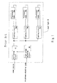
Fig. 1 shows a block diagram of a control circuit in a back light 10 to be used for
this type of liquid crystal display. In the diagram, the back light 10 includes an oscillating
circuit 12, lighting circuits 14a, 14b, and 14c, a light volume adjusting circuit 16, and
fluorescent tubes 18a, 18b, and 18c.
The light volume adjusting circuit 16 receives brightness adjusting input which is
generated in accordance with a luminance adjusting signal from exterior, and outputs, to
the oscillating circuit 12, a light volume adjusting signal for adjusting the fluorescent tubes
18a, 18b, and 18c in brightness. The oscillating circuit 12 generates an alternating voltage
corresponding to the light volume adjusting signal out of the power supplied from a power
source, and outputs the generated alternating voltage to the lighting circuits 14a, 14b, and
14c. The lighting circuits 14a, 14b, and 14c boost the alternating voltage output from the
oscillating circuit 12, and supply the boosted voltages to the fluorescent tubes 18a, 18b,
and 18c. The fluorescent tubes 18a, 18b, and 18c light up at luminances corresponding to
the voltage waveforms supplied.
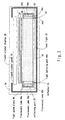
Fig. 2 shows an overview of structure of a light emitting part 10a in the back light
10. The light emitting part 10a has a reflector 20 for accommodating the fluorescent tubes
18a, 18b, and 18c.
The inner surface of the reflector 20 is given a reflecting coat of metal. The
fluorescent tubes 18a, 18b, and 18c are arranged in parallel inside the reflector 20. The
light emitted from the fluorescent tubes 18a, 18b, and 18c radiates out directly or after
reflected from the inner surface of the reflector 20.
In the back light 10 shown in Fig. 1, the single light volume adjusting circuit 16
adjusts the plurality of fluorescent tubes 18a, 18b, and 18c in luminance. On this account,
when the back light 10 produces an output of the minimum luminance, the fluorescent
tubes 18a, 18b, and 18c are lit at their respective minimum luminances. Consequently, the
minimum luminance possible for the back light 10 to output is the sum of the minimum
luminances of the individual fluorescent tubes 18a, 18b, and 18c. When liquid crystal
displays having such a back light are applied to the navigation systems, the screen
brightness cannot be lowered to an appropriate brightness in nighttime use.
According to the structure of the light emitting part 10a of the back light 10 shown
in Fig. 2, the central fluorescent tube 18b faces a smaller area of the reflector 20 and the
outer fluorescent tubes 18a and 18b face greater areas of the reflector 20. The parasitic
capacitance occurring between the fluorescent tube 18b and the reflector 20 is therefore
smaller than the parasitic capacitance occurring between the fluorescent tube 18a and the
reflector 20, and the parasitic capacitance occurring between the fluorescent tube 18c and
the reflector 20.
Therefore, the current to flow through the fluorescent tube 18b is greater than the
currents to flow the fluorescent tubes 18a and 18c. This shortens the life of the
fluorescent tube 18b more than the lives of the fluorescent tubes 18a and 18c. In general,
fluorescent tubes of a back light cannot be replaced separately. Thus, the entire back light
must be replaced when any one of the fluorescent tubes no longer works. That is, the life
of a back light becomes shorter depending on the fluorescent tube of the shortest life.
Recently, parts of the liquid crystal displays tend to get smaller in size due to a
growing demand for liquid crystal panels of larger size. The reflectors accommodating the
fluorescent tubes of the back lights also have the inclination to shrink in size. This results
in reducing interior spaces of the reflectors and easy trapping of heat within the reflectors.
Consequently, if a plurality of fluorescent tubes is used, there is a possibility that
concentrate generated heat therein may hamper sufficient heat dissipation.
SUMMARY OF THE INVENTION
It is an object of the present invention to provide a back light capable of further
reducing the minimum value of luminance and a liquid crystal display equipped with this
back light.
Another object of the present invention is to prolong the life of the fluorescent
tubes constituting the back light.
Another object of the present invention is to dissipate heat produced by the light
sources constituting the back light with higher efficiency.
According to one of the aspects of the back light and the liquid crystal display of
the present invention, a brightness control circuit selects at least one of light volume
adjusting signals and fixes output of the light volume adjusting signals other than the
selected light volume adjusting signal. On this account, the light sources other than the
light source corresponding to the selected light volume adjusting signal will not change in
luminance. The light sources are arranged, for example, behind a liquid crystal panel.
When a luminance adjusting signal changes, the brightness control circuit adjusts
the selected light volume adjusting signal and outputs the same to a lighting control circuit
so that the luminance of the back light (the total luminance of the light sources) approaches
a luminance indicated by the luminance adjusting signal. The lighting control circuit
receiving the adjusted light volume adjusting signal generates a voltage having a waveform
corresponding to the received light volume adjusting signal and applies the same to the
light source. The light source is on at a luminance corresponding to the waveform of the
voltage applied from the lighting control circuit. Then, the light source corresponding to
the selected light volume adjusting signal is adjusted in luminance, so that the back light
changes in luminance. Subsequently, the brightness control circuit fixes the output of the
selected light volume adjusting signal and selects one or more of the light volume adjusting
signals according to need. Then, the same luminance adjustment as described above is
performed.
The back light of the present invention can adjust the light volume adjusting
signals one by one to change the luminances of the light sources, whereby the luminance
adjustment control of the back light is facilitated. Since the plurality of light sources can be
successively adjusted in luminance, minimum light sources alone can be turned on at their
respective minimum luminances with the rest of the light sources turned off. For example,
turning only a single light source on at its minimum luminance enables the minimum
luminance of a single light source to be the minimum luminance of the back light.
Consequently, when the back light and the liquid crystal display of the present invention are
used in dark places, the screen brightness can be lowered to an appropriate brightness.
According to another aspect of the back light of the present invention, an adjusting
part adjusts the selected light volume adjusting signal to lower its corresponding light
source in luminance (luminance-down operation) when the luminance indicated by the
luminance adjusting signal is smaller than the actual total luminance of the light sources.
A detecting part outputs a detecting signal to the adjusting part when the luminance of the
light source corresponding to the selected light volume adjusting signal is minimum.
On receiving the detecting signal, the adjusting part fixes the selected light volume
adjusting signal to a turn-off level to turn off the corresponding light source (turn-off
operation), and selects anew at least one of the rest of the light volume adjusting signals
corresponding to a lit light source (selecting operation). In this state, when the luminance
indicated by the luminance adjusting signal is smaller than the actual luminance of the back
light, the adjusting part adjusts the newly selected light volume adjusting signal to lower
the corresponding light source in luminance.
The adjusting part thus performs the luminance-down operation, turn-off
operation, and selecting operation in succession to adjust the luminance of the back light.
Since the reception of the detecting signal can facilitate detecting that the light source has
reached its minimum luminance, the control of lowering the luminance of the back light can
be simplified.
According to another aspect of the back light of the present invention, the
adjusting part temporarily adjusts the light volume adjusting signal corresponding to at
least one of the lit light sources in synchronization with the selected light volume adjusting
signal's turning to the turn-off level, thereby enhancing the corresponding light source in
luminance temporarily. Consequently, the back light can be prevented from dropping in
luminance when a light source lit at its minimum luminance is turned off.
According to another aspect of the back light of the present invention, the
detecting part includes a monitoring circuit for directly detecting currents supplied to the
light sources. The detecting part can thus detect the luminances of the light sources with
higher precision. That is, the detecting part can detect more precisely that light sources
are lit at the minimum luminances. This allows the detecting part to output the detecting
signal to the adjusting part with more accurate timing. As a result, the detecting part can
perform precise control of lowering the luminance of the back light.
According to another aspect of the back light of the present invention, a
fluorescent tube causing a smaller parasitic capacitance with the reflector is subjected to an
effective voltage relatively lower than that applied to the rest of the fluorescent tubes.
Consequently, the fluorescent tube with smaller parasitic capacitance is supplied with a
current smaller than the rest of the fluorescent tubes are. The fluorescent tube with
smaller parasitic capacitance leaks a current smaller than the rest of the fluorescent tubes
do, resulting in equalizing the currents which contribute to light emission of the fluorescent
tubes. The lives of fluorescent tubes can thus be made equal to each other. As a result,
the life of the back light can be prolonged.
According to another aspect of the back light of the present invention, a
fluorescent tube causing a smaller parasitic capacitance with the reflector is smaller in
diameter than the rest of the fluorescent tubes, and this is the smaller the diameter, the
higher the impedance. Consequently, given that the same effective voltage is applied to all
the fluorescent tubes, the fluorescent tube with higher impedance is supplied with a current
smaller than the rest of the fluorescent tubes are. Here, the fluorescent tube with higher
impedance leaks a current smaller than the rest of the fluorescent tubes do, so that the
amounts of the currents contributing to light emission of the fluorescent tubes become
equal to each other. This enables the fluorescent tubes to be identical in life. The life of
the back light can be prolonged accordingly.
According to another aspect of the back light of the present invention, the
fluorescent tube causing a smaller parasitic capacitance with the reflector is higher in
internal gas pressure than the rest of the fluorescent tubes, and this is the smaller the
internal gas pressure, the higher the impedance. Consequently, given that the same
effective voltage is applied to all the fluorescent tubes, the fluorescent tube with higher
impedance is supplied with a current smaller than the rest of the fluorescent tubes are.
Here, the fluorescent tube with higher impedance leaks a current smaller than the rest of
the fluorescent tubes do so that the amounts of the currents contributing to light emission
of the fluorescent tubes become equal to each other. This enables the lives of the
fluorescent tubes to be identical. The life of the back light can be prolonged accordingly.
According to another aspect of the back light of the present invention, each
reflector accommodates a single light source. This allows dissipation of heat produced by
the light sources with higher efficiency.
In addiction, the parasitic capacitances occurring between the light sources and the
respective reflectors can be substantially equalized so that the amounts of the current
leakage from the light sources to the respective reflectors can be also equalized.
Accordingly, the amounts of the currents contributing to light emission of the light sources
become equal to each other, whereby the light sources can be made identical in life. As a
result, the life of the back light can be prolonged.
BRIEF DESCRIPTION OF THE DRAWINGS
The nature, principle, and utility of the invention will become more apparent from
the following detailed description when read in conjunction with the accompanying
drawings in which like parts are designated by identical reference numbers, in which:
DESCRIPTION OF THE PREFERRED EMBODIMENTS
Hereinafter, embodiments of the present invention will be described with reference
to the drawings.
Fig. 3 shows a first embodiment of the liquid crystal display of the present
invention. In the diagram, a liquid crystal display 28 includes a liquid crystal panel 30, a
back light 32, and a case 34 for accommodating the liquid crystal panel 30 and the back
light 32.
The liquid crystal panel 30 has a structure that liquid crystal is sealed between two
transparent glass plates which are opposed to each other with a predetermined spacing.
The liquid crystal panel 30 is of TN (Twisted Nematic) type, for example. The liquid crystal
panel 30 is not limited to TN type but may be of, e.g., VA (Vertically Aligned) type.
The back light 32 includes a prism sheet 36, a diffusion sheet 38, a light guide
plate 40 (light pipe), a reflecting sheet 42, and light emitting parts 44A arranged on both
sides of the light guide plate 40, respectively, as well as a brightness control circuit 48 and
lighting control circuits 50a, 50b, and 50c which are shown in Fig. 4 to be seen later. The
light emitting parts 44A contain fluorescent tubes 46a, 46b, and 46c each.
The prism sheet 36 is arranged behind the liquid crystal panel 30. The diffusion
sheet 38 is arranged behind the prism sheet 36. The light guide plate 40 is arranged
behind the diffusion sheet 38 with its light emitting side toward the diffusion sheet 38.
The light guide plate 40 is made of transparent synthetic resin such as acrylic, and has a
generally flat shape. The reflecting sheet 42 is arranged on the back of the light guide
plate 40.
The light emitting parts 44A have a reflector 45 of U-shaped section. The light
emitting parts 44A are arranged with the apertures of the respective reflectors 45 toward
sides of the light guide plate 40. The inner surfaces of the reflectors 45 are provided with
a reflecting part 52 (reflecting coat) for reflecting light emitted from the fluorescent tubes
46a, 46b, and 46c. Incidentally, the reflectors 45 are not limited to the foregoing
configuration. For example, reflectors of semicircular section may be used.
The fluorescent tubes 46a, 46b, and 46c are identical to one another. The
fluorescent tubes 46a, 46b, and 46c are arranged at regular intervals in the respective
reflectors 45 so as to face the sides of the light guide plate 40. The fluorescent tubes 46a,
46b, and 46c are subjected to voltages from the lighting control circuits 50a, 50b, and 50c
to be described later, and light up at luminances corresponding to the waveforms of these
voltages. The minimum luminances possible for the fluorescent tubes 46a, 46b, and 46c
to light at with stability are approximately 20% the maximum luminances.
In the present embodiment, luminance adjustment control of the fluorescent tubes
46a, 46b, and 46c accommodated in one of the light emitting parts 44A and of the
fluorescent tubes 46a, 46b, and 46c accommodated in the other light emitting part 44A are
performed in synchronization with each other. For this reason, the following description
will exclusively deal with the luminance adjustment control of the fluorescent tubes 46a,
46b, and 46c accommodated in one of the light emitting parts 44A.
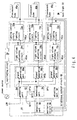
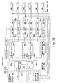
Fig. 4 shows the details of control in the back light 32. The back light 32 has the
brightness control circuit 48, the lighting control circuits 50a, 50b, and 50c, an oscillating
circuit 54, and the fluorescent tubes 46a, 46b, and 46c. The brightness control circuit 48
is composed of a detecting part 56 and an adjusting part 58.
The detecting part 56 includes a monitoring circuit 60. The monitoring circuit 60
detects the currents supplied to the fluorescent tubes 46a, 46b, and 46c, and outputs the
luminance of the back light 32 (the total luminance of the fluorescent tubes 46a, 46b, and
46c) determined from the detected currents to the adjusting part 58 as a luminance
detecting signal VD. The monitoring circuit 60 outputs a detecting signal DET1 to the
adjusting part 58 when it detects that a fluorescent tube (any of 46a, 46b, and 46c) reaches
a minimum luminance.
The adjusting part 58 has a comparing unit 62, a selecting unit 64, and signal
generating units 66a, 66b, and 66c. The comparing unit 62 receives a luminance adjusting
signal LUM for adjusting the luminance of the back light 32 from exterior. The comparing
unit 62 also receives the luminance detecting signal VD which indicates the luminance of
the back light 32. The comparing unit 62 outputs a gap between the luminance indicated
by the luminance adjusting signal LUM and the luminance of the back light 32 indicated by
the luminance gap signal GAP. The comparing unit 62 also outputs a detecting signal
DET2 to the selecting unit 64 in synchronization with the detecting signal DET1.
The selecting unit 64 outputs any one of selecting signals OPTa, OPTb, and OPTc all
the time (always keeps any one of them at high level). The selecting signal OPTa is output
to the signal generating unit 66a. The selecting signal OPTb is output to the signal
generating unit 66b. The selecting signal OPTc is output to the signal generating unit 66c.
The selecting unit 64 outputs the selecting signal OPTa when the back light 32 is at
the maximum in luminance. Upon receiving the detecting signal DET2 while outputting the
selecting signal OPTa, the selecting unit 64 stops outputting the selecting signal OPTa
(turns the selecting signal OPTa to low level) in synchronization with the reception and
outputs the selecting signal OPTb (turns the selecting signal OPTb to high level). Upon
receiving the detecting signal DET2 while outputting the selecting signal OPTb, the selecting
unit 64 stops outputting the selecting signal OPTb (turns the selecting signal OPTb to low
level) in synchronization with the reception and outputs the selecting signal OPTc (turns the
selecting signal OPTc to high level). Upon receiving the detecting signal DET2 while
outputting the selecting signal OPTc, the selecting unit 64 keeps outputting the selecting
signal OPTc without any change in output.
The signal generating unit 66a, while receiving the selecting signal OPTa of high
level, operates to adjust the fluorescent tube 46a in luminance. More specifically, the
signal generating unit 66a outputs, to the lighting control circuit 50a, a light volume
adjusting signal ADJa for adjusting the luminance of the fluorescent tube 46a so that the
luminance gap signal GAP decreases. Moreover, in synchronization with the falling edge of
the selecting signal OPTa, the signal generating unit 66a fixes the light volume adjusting
signal ADJa to a turn-off level for turning off the fluorescent tube 46a.
The signal generating unit 66b, while receiving the selecting signal OPTb of high
level, operates to adjust the fluorescent tube 46b in luminance. More specifically, the
signal generating unit 66b outputs, to the lighting control circuit 50b, a light volume
adjusting signal ADJb for adjusting the luminance of the fluorescent tube 46b so that the
luminance gap signal GAP decreases. Moreover, in synchronization with the falling edge of
the selecting signal OPTb, the signal generating unit 66b fixes the light volume adjusting
signal ADJb to a turn-off level for turning off the fluorescent tube 46b.
The signal generating unit 66c, while receiving the selecting signal OPTc of high
level, operates to adjust the fluorescent tube 46c in luminance. More specifically, the
signal generating unit 66c outputs, to the lighting control circuit 50c, a light volume
adjusting signal ADJc for adjusting the luminance of the fluorescent tube 46c so that the
luminance gap signal GAP decreases.
The signal generating units 66a, 66b, and 66c fix the output of the respective light
volume adjusting signals ADJa, ADJb, and ADJc unless receiving the selecting signals OPTa,
OPTb, and OPTc (while the selecting signals OPTa, OPTb, and OPTc are at low level).
Now, the light volume adjusting signal ADJb to be output from the signal
generating unit 66b is set to be relatively smaller than the light volume adjusting signal
ADJa and the light volume adjusting signal ADJc. On this account, the effective voltage that
the lighting control circuit 50b applies to the fluorescent tube 46b is relatively lower than
the effective voltage that the lighting control circuit 50a applies to the fluorescent tube 46a
and the effective voltage that the lighting control circuit 50 applies to the fluorescent tube
46c.
To put it in details, the fluorescent tube 46b arranged in the center of the reflector
45 shown in Fig. 3 faces a smaller area of the reflecting part 52 than the outer fluorescent
tubes 46a and 46c do. That is, the parasitic capacitance occurring between the fluorescent
tube 46b and the reflector 45 is smaller than the parasitic capacitance occurring between
the fluorescent tube 46a and the reflector 45 and the parasitic capacitance occurring
between the fluorescent tube 46c and the reflector 45. This makes the leakage current
from the fluorescent tube 46b to the reflector 45 smaller than the leakage currents from the
fluorescent tubes 46a and 46c to the reflector 45. When the effective voltage to be applied
to the fluorescent tube 46b is made relatively lower than the effective voltages to be applied
to the fluorescent tubes 46a and 46c as mentioned above, the current supplied to the
fluorescent tube 46b becomes smaller than the currents supplied to the fluorescent tubes
46a and 46c. Here, the current leaking from the fluorescent tube 46b of smaller parasitic
capacitance to the reflector 45 is smaller than the currents leaking from the fluorescent
tubes 46a and 46c. Then, the fluorescent tubes 46a, 46b, and 46c turn out to be identical
in the current that contributes to light emission.
The lighting control circuit 50a is formed for the fluorescent tube 46a, and has a
light volume adjusting circuit 70a and a lighting circuit 72a. The lighting control circuit
50b is formed for the fluorescent tube 46b, and has a light volume adjusting circuit 70b and
a lighting circuit 72b. The lighting control circuit 50c is formed for the fluorescent tube
46c, and has a light volume adjusting circuit 70c and a lighting circuit 72c.
The light volume adjusting circuits 70a, 70b, and 70c are supplied with an
alternating voltage from the oscillating circuit 54. The light volume adjusting circuit 70a
receives the light volume adjusting signal ADJa, adjusts the alternating voltage in amplitude
according to the luminance indicated by the light volume adjusting signal ADJa, and outputs
the adjusted alternating voltage to the lighting circuit 72a. The light volume adjusting
circuit 70b receives the light volume adjusting signal ADJb, adjusts the alternating voltage in
amplitude according to the luminance indicated by the light volume adjusting signal ADJb,
and outputs the adjusted alternating voltage to the lighting circuit 72b. The light volume
adjusting circuit 70c receives the light volume adjusting signal ADJc, adjusts the alternating
voltage in amplitude according to the luminance indicated by the light volume adjusting
signal ADJc, and outputs the adjusted alternating voltage to the lighting circuit 72c.
Each of the lighting circuits 72a, 72b, and 72c boosts the alternating voltage
supplied from the light volume adjusting circuit and applies the boosted voltage to the
corresponding fluorescent tube (any of 46a, 46b, and 46c).
Incidentally, in the present embodiment, the alternative voltages are adjusted in
amplitude (effective value) to adjust the luminances of the respective fluorescent tubes 46a,
46b, and 46c. Otherwise, the alternative voltages to be applied to the fluorescent tubes
may be adjusted in period (duty ratio control) to adjust the luminances of the respective
fluorescent tubes.
Now, description will be given of the luminance adjustment of the back light 32
described above.
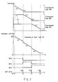
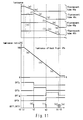
Fig. 5 shows luminance variations of the fluorescent tubes 46a, 46b, and 46c, and
the back light 32. In this example, in an initial state (at time t0), the signal generating units
66a, 66b, and 66c shown in Fig. 4 output light volume adjusting signals ADJa, ADJb, and
ADJc for lighting the corresponding fluorescent tubes 46a, 46b, and 46c at the maximum
luminances, respectively. The selecting unit 64 outputs the selecting signal OPTa to select
the signal generating unit 66a. The fluorescent tubes 46a, 46b, and 46c are lit at their
respective maximum luminances. That is, at time t0, the back light 32 is at the maximum
in luminance.
In this example, the comparing unit 62 receives, at time t1, a luminance adjusting
signal LUM indicating that the back light 32 is to be minimized in luminance. Here, the
luminance indicated by the luminance adjusting signal LUM is smaller than the luminance
indicated by the luminance detecting signal VD. The comparing unit 62 thus outputs a
luminance gap signal GAP for lowering the luminance of the back light. The signal
generating unit 66a is in a luminance adjustable state, receiving the selecting signal OPTa of
high level. The signal generating unit 66a outputs to the light volume adjusting circuit 70a
a light volume adjusting signal ADJa for lowering the luminance of the fluorescent tube 46a
(luminance-down operation).
Consequently, the fluorescent tube 46a gradually decreases in luminance (Fig. 5(a)).
With the decreasing luminance of the fluorescent tube 46a, the back light 32 also decreases
in luminance (Fig. 5(b)). Since the output of the signal generating units 66b and 66c is
fixed, the fluorescent tubes 46b and 46c have no change in luminance (Fig. 5(c)).
At time t2, the luminance of the fluorescent tube 46a reaches the minimum
luminance, and the detecting part 56 outputs the detecting signal DET1 (Fig. 5(d)). In
synchronization with the reception of the detecting signal DET1, the comparing unit 62
outputs the detecting signal DET2 (Fig. 5(d)). In response to the detecting signal DET2, the
selecting unit 64 turns the selecting signal OPTa to low level and turns the selecting signal
OPTb to high level. In synchronization with the falling edge of the selecting signal OPTa,
the signal generating unit 66a fixes the light volume adjusting signal ADJa to the turn-off
level for turning off the fluorescent tube 46a (turn-off operation). Then, the fluorescent
tube 46a goes out (Fig. 5(e)). The signal generating unit 66b receives the selecting signal
OPTb of high level and enters a luminance adjustable state. The signal generating unit 66b
outputs to the light volume adjusting circuit 70b a light volume adjusting signal ADJb for
lowering the luminance of the fluorescent tube 46b (luminance-down operation).
Consequently, the fluorescent tube 46b decreases in luminance (Fig. 5(f)). With the
decreasing luminance of the fluorescent tube 46b, the back light 32 also decreases in
luminance (Fig. 5(g)).
At time t3, the luminance of the fluorescent tube 46b reaches the minimum
luminance, and the detecting part 56 outputs the detecting signal DET1 (Fig. 5(h)). In
synchronization with the detecting signal DET1, the comparing unit 62 outputs the
detecting signal DET2 (Fig. 5(h)). In response to the detecting signal DET2, the selecting
unit 64 turns the selecting signal OPTb to low level and turns the selecting signal OPTc to
high level. In synchronization with the falling edge of the selecting signal OPTb, the signal
generating unit 66b fixes the light volume adjusting signal ADJb to the turn-off level for
turning off the fluorescent tube 46b (turn-off operation). Then, the fluorescent tube 46b
goes out (Fig. 5(i)). The signal generating unit 66c receives the selecting signal OPTc of
high level and enters a luminance adjustable state. The signal generating unit 66c outputs
to the light volume adjusting circuit 70c a light volume adjusting signal ADJc for lowering
the luminance of the fluorescent tube 46c (luminance-down operation). Consequently, the
fluorescent tube 46c decreases in luminance (Fig. 5(j)). With the decreasing luminance of
the fluorescent tube 46c, the back light 32 also decreases in luminance (Fig. 5(k)).
At time t4, the luminance of the fluorescent tube 46c reaches the minimum
luminance, and the detecting part 56 outputs the detecting signal DET1 (Fig. 5(I)). In
synchronization with the detecting signal DET1, the comparing unit 62 outputs the
detecting signal DET2 (Fig. 5(I)). Fluorescent tubes lit here are the fluorescent tube 46c
alone. That is, at time t4, the back light 32 becomes minimum in luminance. Here, the
luminance indicated by the luminance detecting signal VD becomes equal to the luminance
indicated by the luminance adjusting signal LUM, and the comparing unit 62 outputs a
luminance gap signal GAP of 0 in magnitude. When the fluorescent tube 46c lit to the end
becomes minimum in luminance, the brightness control circuit 48 makes no turn-off
operation and keeps the fluorescent tube 46c lit at the minimum luminance.
In a case where the fluorescent tubes 46a, 46b, and 46c are lit at their maximum
luminances, the luminance of the back light 32 is maximum. Also, when only a single
fluorescent tube (46c, in this example) in each light emitting part 44A is lit at its minimum
luminance, the luminance of the back light 32 is minimum. Hence, the minimum
luminance of the back light 32 is one-third that of conventional back lights in which all the
fluorescent tubes are lit together at their minimum luminances.
As has been described, according to the present embodiment, the adjusting part 58
has only to receive the detecting signal DET1 to easily detect that any one of the fluorescent
tubes 46a, 46b, and 46c reaches its minimum luminance. Thus, the adjusting part 58 can
easily switch the fluorescent tube to adjust (any one of 46a, 46b, and 46c). This can
facilitate the control in lowering the luminance of the back light 32.
Since the detecting part 56 directly detects the currents supplied to the fluorescent
tubes 46a, 46b, and 46c by using the monitoring circuit 60, it can easily detect that any one
of the fluorescent tubes 46a, 46b, and 46c reaches the minimum luminance.
The fluorescent tube 46b, which causes a smaller parasitic capacitance with the
reflector 45, is subjected to an effective voltage relatively lower than the effective voltages
applied to the other fluorescent tubes 46a and 46c. This can make the florescent tubes
46a, 46b, and 46c identical in the current that contributes to light emission. The
fluorescent tubes 46a, 46b, and 46c can thus be made identical in life. The result is that
the fluorescent tube 46b, causing a smaller parasitic capacitance with the reflector 45, is
prolonged in life, allowing extended life of the back light 32.
Fig. 6 shows a second embodiment of the liquid crystal display of the present
invention. The same elements as those of the first embodiment will be designated by
identical reference numbers or symbols. Detailed description will be omitted of these
elements. A liquid crystal display 28b includes a liquid crystal panel 30, a back light 32b,
and a case 34 for accommodating the liquid crystal panel 30 and the back light 32b.
The back light 32b includes a prism sheet 36, a diffusion sheet 38, a light guide
plate 40, a reflecting sheet 42, light emitting parts 44B arranged on both sides of the light
guide plate 40, a brightness control circuit 48b, and lighting control circuits 50a, 50b, and
50c which are shown in Fig. 5 and to be described later.
The back light 32b has the same configuration as that of the first embodiment
except that the diameters of fluorescent tubes 46d arranged in the centers of reflectors 45
of the light emitting parts 44B are smaller than those of fluorescent tubes 46a and 46c
arranged on both sides of the respective fluorescent tubes 46d, and that signal generating
units 66d and 66e (shown in Fig. 7 to be seen later) are formed instead of the signal
generating units 66b and 66c of the first embodiment.
The fluorescent tubes 46d are smaller in diameter than the fluorescent tubes 46a
and 46c, and thus are higher in impedance than the fluorescent tubes 46a and 46c.
Accordingly, given that the same effective voltage is applied to all the fluorescent tubes 46a,
46d, and 46c, the currents supplied to the fluorescent tubes 46d of higher impedance
become smaller than the currents supplied to the other fluorescent tubes 46a and 46c.
Moreover, as in the first embodiment, the fluorescent tubes 46d arranged in the centers of
the reflectors 45 are less prone to leak currents to the reflectors 45 than the fluorescent
tubes 46a and 46c do. Consequently, the currents leaking from the fluorescent tubes 46d
of higher impedance to the reflector 45 become smaller than the currents leaking from the
fluorescent tubes 46a and 46c. Then, the fluorescent tubes 46a, 46d, and 46c turn out to
be identical in the current that contributes to light emission. Thus, as in the first
embodiment, the fluorescent tubes 46a, 46d, and 46c become identical in life.
In the present embodiment, the lighting control circuits 50a, 50b, and 50c shown
in Fig. 5 to be seen later apply relatively the same effective voltages to the respective
fluorescent tubes 46a, 46d, and 46c.
Now, in the present embodiment, luminance adjustment control of the fluorescent
tubes 46a, 46d, and 46c accommodated in one of the light emitting parts 44B and
luminance adjustment control of the fluorescent tubes 46a, 46d, and 46c accommodated in
the other light emitting part 44B are performed in synchronization with each other. For
this reason, the following description will exclusively deal with the luminance adjustment
control of the fluorescent tubes 46a, 46d, and 46c accommodated in one of the light
emitting parts 44B.
Fig. 7 shows the details of control of the back light 32b.
The signal generating unit 66d receives a luminance gap signal GAP and a selecting
signal OPTb, and outputs to the lighting control circuit 50b a light volume adjusting signal
ADJd for adjusting the luminance of the fluorescent tube 46d. In response to the rising
edge of the selecting signal OPTb, the signal generating unit 66d enhances the light volume
adjusting signal ADJd steeply so that the fluorescent tube 46d increases in luminance as
much as the minimum luminance of the fluorescent tube 46a. Subsequently, while
receiving the selecting signal OPTb of high level, the signal generating unit 66d outputs to
the lighting control circuit 50b a light volume adjusting signal ADJd for adjusting the
luminance of the fluorescent tube 46d so that the luminance gap signal GAP decreases.
Besides, in synchronization with the falling edge of the selecting signal OPTb, the signal
generating unit 66d fixes the light volume adjusting signal ADJd to a turn-off level for
turning off the fluorescent tube 46d.
The signal generating unit 66e receives the luminance gap signal GAP and a
selecting signal OPTc, and outputs to the lighting control circuit 50c a light volume
adjusting signal ADJe for adjusting the luminance of the fluorescent tube 46c. In response
to the rising edge of the selecting signal OPTc, the signal generating unit 66e enhances the
light volume adjusting signal ADJe steeply so that the fluorescent tube 46c increases in
luminance as much as the minimum luminance of the fluorescent tube 46d. Subsequently,
while receiving the selecting signal OPTc of high level, the signal generating unit 66e
outputs to the lighting control circuit 50c a light volume adjusting signal ADJe for adjusting
the luminance of the fluorescent tube 46c so that the luminance gap signal GAP decreases.
Incidentally, the signal generating units 66d and 66e fix the output of the light
volume adjusting signals ADJd and ADJe while the selecting signals OPTb and OPTc are at
low level.
Now, description will be given of the luminance adjustment of the back light 32b
described above.
Fig. 8 shows luminance variations of the fluorescent tubes 46a, 46d, and 46c, and
the back light 32b. In this example, as with the first embodiment, the fluorescent tubes
46a, 46d, and 46c are lit at their respective maximum luminances in an initial state (at time
t0). In addition, the selecting unit 64 outputs the selecting signal OPTa of high level and
keeps the selecting signals OPTb and OPTc at low level.
At time t1, a luminance adjusting signal LUM indicating that the back light 32b is to
be minimized in luminance is supplied, in which case the fluorescent tube 46a gradually
decreases in luminance (Fig. 8(a)). With the decreasing luminance of the fluorescent tube
46a, the back light 32b also decreases in luminance (Fig. 8(b)). Since the output of the
signal generating units 66d and 66e is fixed, the fluorescent tubes 46d and 46c have no
change in luminance (Fig. 8(c)).
At time t2, the luminance of the fluorescent tube 46a reaches the minimum
luminance, and the detecting part 56 outputs the detecting signal DET1 (Fig. 8(d)). In
synchronization with the detecting signal DET1, the comparing unit 62 outputs the
detecting signal DET2 (Fig. 8(d)). In response to the detecting signal DET2, the selecting
unit 64 turns the selecting signal OPTa to low level and turns the selecting signal OPTb to
high level. In synchronization with the falling edge of the selecting signal OPTa, the signal
generating unit 66a fixes the light volume adjusting signal ADJa to the turn-off level for
turning off the fluorescent tube 46a (turn-off operation). Then, the fluorescent tube 46a
goes out (Fig. 8(e)). In response to the rising edge of the selecting signal OPTb, the signal
generating unit 66d enhances the light volume adjusting signal ADJd steeply so that the
fluorescent tube 46d increases in luminance as much as the minimum luminance of the
fluorescent tube 46a (Fig. 8(f)). This prevents the back light 32b from dropping in
luminance due to the turning-off of the fluorescent tube 46a. That is, the back light 32b
makes little variation in luminance when the fluorescent tube 46a is turned off.
Subsequently, while receiving the selecting signal OPTb of high level, the signal
generating unit 66d outputs to the lighting control circuit 50b a light volume adjusting
signal ADJd for adjusting the luminance of the fluorescent tube 46d so that the luminance
gap signal GAP decreases. Consequently, the fluorescent tube 46d decreases in luminance
(Fig. 8(g)). With the decreasing luminance of the fluorescent tube 46d, the back light 32b
also decreases in luminance (Fig. 8(h)).
At time t3, the luminance of the fluorescent tube 46d reaches the minimum
luminance, and the detecting part 56 outputs the detecting signal DET1 (Fig. 8(i)). In
synchronization with the detecting signal DET1, the comparing unit 62 outputs the
detecting signal DET2 (Fig. 8(i)). In response to the detecting signal DET2, the selecting
unit 64 turns the selecting signal OPTb to low level and turns the selecting signal OPTc to
high level. In synchronization with the falling edge of the selecting signal OPTb, the signal
generating unit 66d fixes the light volume adjusting signal ADJd to the turn-off level for
turning off the fluorescent tube 46d (turn-off operation). Then, the fluorescent tube 46d
goes out (Fig. 8(j)). In response to the rising edge of the selecting signal OPTc, the signal
generating unit 66e enhances the light volume adjusting signal ADJe steeply so that the
fluorescent tube 46c increases in luminance as much as the minimum luminance of the
fluorescent tube 46d (Fig. 8(k)). This prevents the back light 32b from dropping in
luminance due to the turning-off of the fluorescent tube 46d. That is, the back light 32b
makes little variation in luminance when the fluorescent tube 46d is turned off.
Subsequently, while receiving the selecting signal OPTc of high level, the signal
generating unit 66e outputs to the lighting control circuit 50c a light volume adjusting
signal ADJe for adjusting the luminance of the fluorescent tube 46c so that the luminance
gap signal GAP decreases. Consequently, the fluorescent tube 46c decreases in luminance
(Fig. 8(I)). With the decreasing luminance of the fluorescent tube 46c, the back light 32b
also decreases in luminance (Fig. 8(m)).
At time t4, the luminance of the fluorescent tube 46c reaches the minimum
luminance, and the detecting part 56 outputs the detecting signal DET1 (Fig. 8(n)). In
synchronization with the detecting signal DET1, the comparing unit 62 outputs the
detecting signal DET2 (Fig. 8(n)). Here, the back light 32b is at the minimum in luminance,
so that the luminance indicated by the luminance detecting signal VD and the luminance
indicated by the luminance adjusting signal LUM become equal. Then, the comparing unit
62 outputs a luminance gap signal GAP of 0 in magnitude. When the fluorescent tube 46c
lit to the end becomes minimum in luminance, the brightness control circuit 48b makes no
turn-off operation and keeps the fluorescent tube 46c lit at the minimum luminance.
As has been described, the liquid crystal display 28b of the present embodiment
can offer the same effects as those of the foregoing first embodiment. Besides, in the
present embodiment, the adjusting part 58b enhances the luminances of the fluorescent
tubes 46d and 46c steeply in turning off the fluorescent tubes 46a and 46d, respectively.
The back light 32b can thus be prevented from changing in luminance due to the
turning-off of the fluorescent tubes 46a and 46d that are lit at the minimum luminances.
The fluorescent tubes 46d arranged in the centers of the reflectors 45 have a
diameter smaller than the diameter of the outer fluorescent tubes 46a and 46c. Hence, the
fluorescent tubes 46d of smaller parasitic capacitance can be increased in impedance.
Consequently, even if relatively the same effective voltages are applied to all the fluorescent
tubes 46a, 46d, and 46c, the fluorescent tubes 46a, 46d, and 46c can be made identical in
the current that contributes to light emission. As a result, the fluorescent tubes 46a, 46d,
and 46c can be made identical in life, allowing extended life of the back light 32b.
In addition, since relatively the same effective voltages may be applied to the
fluorescent tubes 46a, 46d, and 46c, the signal generating units 66a, 66d, and 66e can be
made common in circuitry.
Fig. 9 shows a third embodiment of the liquid crystal display of the present
invention. The same elements as those of the first and second embodiments will be
designated by identical reference numbers or symbols. Detailed description will be omitted
of these elements. A liquid crystal display 28c includes a liquid crystal panel 30, a back
light 32c, and a case 34 for accommodating the liquid crystal panel 30 and the back light
32c.
The back light 32c includes a prism sheet 36, a diffusion sheet 38, a light guide
plate 40, a reflecting sheet 42, and light emitting parts 44C arranged on both sides of the
light guide plate 40, respectively.
The light emitting parts 44C have a reflector 45 each. The light emitting part 44C
on the right of the light guide plate 40 in Fig. 9 accommodates fluorescent tubes 46a, 46g,
and 46c. The light emitting part 44C on the left of the light guide plate 40 in Fig. 9
accommodates fluorescent tubes 46a, 46h, and 46c.
The fluorescent tube 46g and the fluorescent tube 46h are identical to each other.
The fluorescent tubes 46g and 46h are arranged in the centers of the respective reflectors
45. All the minimum luminances and maximum luminances possible for the respective
fluorescent tubes 46a, 46g, 46h, and 46c to light at with stability are approximately the
same.
The fluorescent tubes 46g and 46h have an internal gas pressure higher than that
of the fluorescent tubes 46a and 46c. On this account, the fluorescent tubes 46g and 46h
are higher in impedance than the fluorescent tubes 46a and 46c. Moreover, the
fluorescent tubes 46g and 46h, arranged in the centers of the reflectors 45, cause smaller
parasitic capacitances with the reflectors 45 as in the second embodiment. Thus, the
fluorescent tubes 46g and 46h are less prone to leak currents to the reflectors 45 than the
fluorescent tubes 46a and 46c do.
Consequently, as in the second embodiment, the fluorescent tubes 46a, 46g, 46h,
and 46c become identical in the current that contributes to light emission, provided that the
same effective voltage is applied to all the fluorescent tubes 46a, 46g, 46h, and 46c. The
result is that the fluorescent tubes 46a, 46g, 46h, and 46c become identical in life as with
the first embodiment.
Fig. 10 shows the details of control of the back light 32c. The back light 32c has a
brightness control circuit 48c, two lighting control circuits 50a corresponding to the
fluorescent tubes 46a, respectively, two lighting control circuits 50b corresponding to the
fluorescent tubes 46g and 46h, respectively, two lighting control circuits 50c corresponding
to the fluorescent tubes 46c, respectively, and an oscillating circuit 54.
The lighting control circuits 50a, 50b, and 50c apply relatively the same effective
voltages to the fluorescent tubes 46a, 46g, 46h, and 46c.
The brightness control circuit 48c is composed of a detecting part 56 and an
adjusting part 58c. The adjusting part 58c has a comparing unit 62, a selecting unit 64c,
and signal generating units 66a, 66g, 66h, and 66j.
The selecting unit 64c always outputs (keeps at high level) at least any one of
selecting signals OPTa, OPTg, OPTh, and OPTc. The selecting signal OPTa is output to the
signal generating unit 66a. The selecting signal OPTg is output to the signal generating
unit 66g and the signal generating unit 66h. The selecting signal OPTh is output to the
signal generating unit 66h. The selecting signal OPTc is output to the signal generating
unit 66j.
Now, description will be given of the luminance adjustment of the back light 32c
described above.
Fig. 11 shows luminance variations of the fluorescent tubes 46a, 46g, 46h, and 46c,
and the back light 32c. In this example, as with the first embodiment, the fluorescent
tubes 46a, 46g, 46h, and 46c are lit at their respective maximum luminances in an initial
state (at time t0). Besides, the selecting unit 64c outputs the selecting signal OPTa (keeps
the selecting signal OPTa at high level).
At time t1, a luminance adjusting signal LUM indicating that the back light 32c is to
be minimized in luminance is supplied, in which case the two fluorescent tube 46a gradually
decrease in luminance (Fig. 11(a)). With the decreasing luminances of the fluorescent tubes
46a, the back light 32c also decreases in luminance (Fig. 11(b)). Since the output of the
signal generating units 66g, 66h, and 66j is fixed, the fluorescent tubes 46g, 46h, and 46c
have no change in luminance (Fig. 11(c)).
At time t2, the luminances of the fluorescent tubes 46a reach the minimum
luminances, and the detecting part 56 outputs the detecting signal DET1 (Fig. 11(d)). In
synchronization therewith, the comparing unit 62 outputs the detecting signal DET2 (Fig.
11(d)). In response to the detecting signal DET2, the selecting unit 64c turns the selecting
signal OPTa to low level and turns the selecting signal OPTc to high level. In
synchronization with the falling edge of the selecting signal OPTa, the signal generating unit
66a fixes the light volume adjusting signal ADJa to a turn-off level for turning off the
fluorescent tubes 46a (turn-off operation). Then, the two fluorescent tubes 46a go out (Fig.
11(e)). In response to the rising edge of the selecting signal OPTc, the signal generating
unit 66j enhances a light volume adjusting signal ADJj steeply so that the two fluorescent
tubes 46c increase in luminance as much as the minimum luminances of the two
fluorescent tubes 46a (Fig. 11(f)). This prevents the back light 32c from dropping in
luminance due to the turning-off of the two fluorescent tubes 46a. That is, the back light
32c makes little variation in luminance when the two fluorescent tubes 46a are turned off.
Subsequently, while receiving the selecting signal OPTc of high level, the signal
generating unit 66j outputs a light volume adjusting signal ADJj for adjusting the
luminances of the fluorescent tubes 46c so that the luminance gap signal GAP decreases.
Consequently, the two fluorescent tubes 46c decrease in luminance (Fig. 11(g)). With the
decreasing luminances of the fluorescent tubes 46c, the back light 32c also decreases in
luminance (Fig. 11(h)).
At time t3, the luminances of the two fluorescent tubes 46c reach the minimum
luminances, and the detecting part 56 outputs the detecting signal DET1 (Fig. 11(i)). In
synchronization therewith, the comparing unit 62 outputs the detecting signal DET2 (Fig.
11(i)). In response to the detecting signal DET2, the selecting unit 64c turns the selecting
signal OPTc to low level and turns the selecting signals OPTg and OPTh to high level. In
synchronization with the falling edge of the selecting signal OPTc, the signal generating unit
66j fixes the light volume adjusting signal ADJj to a turn-off level for turning off the
fluorescent tubes 46c (turn-off operation). Then, the two fluorescent tubes 46c go out (Fig.
11(j)).
In response to the rising edge of the selecting signal OPTg, the signal generating
unit 66g enhances a light volume adjusting signal ADJg steeply so that the fluorescent tube
46g increases in luminance as much as the minimum luminance of a single fluorescent tube
46c (Fig. 11(k)). In response to the rising edge of the selecting signal OPTh, the signal
generating unit 66h enhances a light volume adjusting signal ADJh steeply so that the
fluorescent tube 46h increases in luminance as much as the minimum luminance of a single
fluorescent tube 46c (Fig. 11(I)). This prevents the back light 32c from dropping in
luminance due to the turning-off of the two fluorescent tubes 46c. That is, the back light
32c makes little variation in luminance when the two fluorescent tubes 46c are turned off.
Subsequently, while receiving the selecting signal OPTg of high level, the signal
generating unit 66g outputs a light volume adjusting signal ADJg for adjusting the
luminance of the fluorescent tube 46g so that the luminance gap signal GAP decreases.
Consequently, the fluorescent tube 46g decreases in luminance (Fig. 11(m)). In the
meantime, the signal generating unit 66h, while receiving the selecting signal OPTh of high
level, outputs a light volume adjusting signal ADJh for adjusting the luminance of the
fluorescent tube 46h so that the luminance gap signal GAP decreases. Consequently, the
fluorescent tube 46h decreases in luminance (Fig. 11(n)). With the decreasing luminances
of the fluorescent tubes 46g and 46h, the back light 32c also decreases in luminance (Fig.
11(o)).
At time t4, the luminances of the fluorescent tubes 46g and 46h reach the
minimum luminances, and the detecting part 56 outputs the detecting signal DET1 (Fig.
11(p)). In synchronization therewith, the comparing unit 62 outputs the detecting signal
DET2 (Fig. 11(p)). In response to the detecting signal DET2, the selecting unit 64c turns the
selecting signal OPTg to low level. Here, the selecting signal OPTh is kept at high level. In
synchronization with the falling edge of the selecting signal OPTg, the signal generating
unit 66g fixes the light volume adjusting signal ADJg to a turn-off level for turning off the
fluorescent tube 46g (turn-off operation). Then, the fluorescent tube 46g goes out (Fig.
11(q)).
In response to the falling edge of the selecting signal OPTg, the signal generating
unit 66h enhances the light volume adjusting signal ADJh steeply so that the fluorescent
tube 46h increases in luminance as much as the minimum luminance of the fluorescent
tube 46g (Fig. 11(r)). This prevents the back light 32c from dropping in luminance due to
the turning-off of the fluorescent tube 46g. That is, the back light 32c makes little
variation in luminance when the fluorescent tube 46g is turned off.
At time t5, the luminance of the fluorescent tube 46h reaches the minimum
luminance, and the detecting part 56 outputs the detecting signal DET1 (Fig. 11(s)). In
synchronization therewith, the comparing unit 62 outputs the detecting signal DET2 (Fig.
11(s)). Here, the back light 32c is at the minimum in luminance, so that the luminance
indicated by the luminance detecting signal VD and the luminance indicated by the
luminance adjusting signal LUM become equal. Then, the comparing unit 62 outputs a
luminance gap signal GAP of 0 in magnitude. When the fluorescent tube 46h lit to the end
becomes minimum in luminance, the brightness control circuit 48c makes no turn-off
operation and keeps the fluorescent tube 46h lit at the minimum luminance.
As has been described, the liquid crystal display 28c of the present embodiment
can offer the same effects as those of the foregoing first and second embodiments.
Besides, in the present embodiment, when the luminance adjusting signal LUM for
minimizing the luminance of the back light is received, only a single fluorescent tube 46h is
lit at its minimum luminance while the other fluorescent tubes 46a, 46c, and 46g are turned
off. The maximum luminance possible for the back light 32c to output is for situations
where the six fluorescent tubes 46a, 46g, 46h, and 46c are lit at their maximum luminances.
On this account, the minimum luminance of the back light 32c can be rendered one-sixth
that of conventional back lights in which all the fluorescent tubes are lit together at the
minimum luminances.
The fluorescent tubs 46g and 46h arranged in the centers of the reflectors 45 have
an internal gas pressure higher than the internal gas pressure of the outer fluorescent tubes
46a and 46c. The fluorescent tubes 46g and 46h of smaller parasitic capacitance can thus
be increased in impedance. Consequently, the fluorescent tubes 46a, 46g, 46h, and 46c
can be made identical in the current that contributes to light emission, provided that
relatively the same effective voltages are applied to all the fluorescent tubes 46a, 46g, 46h,
and 46c. As a result, the fluorescent tubes 46a, 46g, 46h, and 46c can be made identical
in life, allowing extended life of the back light 32c.
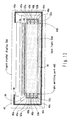
Fig. 12 shows a fourth embodiment of the liquid crystal display of the present
invention. The same elements as those of the first and second embodiments will be
designated by identical reference numbers or symbols. Detailed description will be omitted
of these elements. A liquid crystal display 28d includes a liquid crystal panel 30, a case 34,
and a back light 32d of the present embodiment.
The back light 32d has light emitting parts 44D arranged on both sides of a light
guide plate 40, respectively. In this embodiment, each light emitting part 44D has
reflectors 45a, 45b, and 45c for accommodating fluorescent tubes 46a, 46b, and 46c,
respectively. The brightness control circuit and the lighting control circuits are the same as
in the second embodiment.
The reflectors 45a, 45b, and 45c are identical to one another. The inner surfaces
of the reflectors 45a, 45b, and 45c are provided with reflecting parts 52a, 52b, and 52c
(reflecting coats) for reflecting the light emitted from the fluorescent tubes 46a, 46b, and
46c, respectively. The reflectors 45a, 45b, and 45c are arranged with their apertures
toward the sides of the light guide plate 40.
The physical relationship between the fluorescent tube 46a and the reflector 45a,
the physical relationship between the fluorescent tube 46b and the reflector 45b, and the
physical relationship between the fluorescent tube 46c and the reflector 45c are identical.
For this reason, all the parasitic capacitances occurring between the fluorescent tubes 46a,
46b, and 46c, and the reflectors 45a, 45b, and 45c accommodating the respective
fluorescent tubes 46a, 46b, and 46c are the same.
The areas of parts of the reflectors 45a, 45b, and 45c where there is no obstacle
between the fluorescent tubes 46a, 46b, and 46c and the reflectors 45a, 45b, and 45c, and
they face to each other, respectively, are greater than in the cases where a single reflector
accommodates three fluorescent tubes 46a, 46b, and 46c. This allows improved
conductive efficiency of dissipating the heat produced by the lit fluorescent tubes 46a, 46b,
and 46c to the reflectors 45a, 45b, and 45c.
As has been described, the liquid crystal display 28d of the present embodiment
can offer the same effects as those of the foregoing second embodiment. In addition, the
present embodiment provides the reflectors 45a, 45b, and 45c for accommodating the
fluorescent tubes 46a, 46b, and 46c, respectively. The heat produced by the fluorescent
tubes 46a, 46b, and 46c can thus be dissipated with higher efficiency.
Accommodating the fluorescent tubes 46a, 46b, and 46c in the reflectors 45a, 45b,
and 45c, respectively, equalizes the parasitic capacitances between the fluorescent tubes
46a, 46b, and 46c and the reflectors 45a, 45b, and 45c. Consequently, the currents
flowing through the respective fluorescent tubes 46a, 46b, and 46c can be made identical
so that the fluorescent tubes 46a, 46b, and 46c become equal in life. As a result, the life of
the back light 32d can be prolonged.
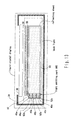
Incidentally, the foregoing first to fourth embodiments have dealt with the cases
where the light emitting parts (reflectors and fluorescent tubes) are arranged on both sides
of the light guide plate 40, respectively. However, the present invention is not limited to
such embodiments. For example, a light emitting part may be arranged on either side of
the light guide plate, as shown in Fig. 13.
The invention is not limited to the above embodiments and various modifications
may be made without departing from the spirit and scope of the invention. Any
improvement may be made in part or all of the components.