EP1610106A1 - Weight detecting device - Google Patents
Weight detecting device Download PDFInfo
- Publication number
- EP1610106A1 EP1610106A1 EP04723844A EP04723844A EP1610106A1 EP 1610106 A1 EP1610106 A1 EP 1610106A1 EP 04723844 A EP04723844 A EP 04723844A EP 04723844 A EP04723844 A EP 04723844A EP 1610106 A1 EP1610106 A1 EP 1610106A1
- Authority
- EP
- European Patent Office
- Prior art keywords
- weight
- vibration
- load cell
- detecting means
- detecting
- Prior art date
- Legal status (The legal status is an assumption and is not a legal conclusion. Google has not performed a legal analysis and makes no representation as to the accuracy of the status listed.)
- Withdrawn
Links
Images




Classifications
-
- G—PHYSICS
- G01—MEASURING; TESTING
- G01G—WEIGHING
- G01G23/00—Auxiliary devices for weighing apparatus
- G01G23/06—Means for damping oscillations, e.g. of weigh beams
- G01G23/10—Means for damping oscillations, e.g. of weigh beams by electric or magnetic means
Definitions
- the present invention relates to a weight detecting apparatus, and particularly to a weight detecting apparatus for detecting a weight of an object placed thereon with high precision, and belongs to a field of weight detecting technology.
- Weight detecting apparatuses which detect weights of objects by weight detectors such load cells, have been widely used in various fields.
- Patent reference 1 Japanese Laid-Open Patent Publication No. H8-110261
- patent reference 2 Japanese Laid-Open Patent Publication No. H8-136330
- weight detecting apparatuses which are configured to eliminate disturbance due to vibrations for further improving detection precision.
- the weight detecting apparatus disclosed in the patent reference 1 includes a weight detecting load cell (load cell for measurement) A1 and a vibration detecting load cell (load cell for dummy) A2, which are fixed at their fixed ends to a fixed base (floor) B.
- An object table C placing an object X is coupled to a free end of weight detecting load cell A1.
- a balance weight (i.e., a metal weight of a known weight) D is attached to a free end of vibration detecting load cell A2.
- the weight detecting load cell A1 issues a detection signal produced by superimposing floor vibration components on the weight of the object X
- the vibration detecting load cell A2 issues a detection signal according to floor vibration components.
- the weight and vibration detecting load cells A1 and A2 have cell sensitivity characteristics usually varying according to magnitudes and others of target loads. For allowing arithmetic processing between the detection signals provided by these load cells A1 and A2, arithmetic processing for correction is effected on the detection signals.
- processing is performed to subtract the detection signal from the vibration detecting load cell A2, which is arithmetically processed for correction in a predetermined manner, from the detection signal of the weight detecting load cell A1.
- vibration components on a device installation side are removed from the detection signal of the weight detecting load cell A1 so that only the signal matching with the weight of the object X can be obtained.
- the weight detecting apparatus disclosed in the patent reference 2 has a weight detecting load cell (first load cell) A1 having a fixed end, which is fixed to the fixed base B on the floor.
- a transporting conveyor (transporting means) C1 is fixed to a free end of the weight detecting load cell A1 via a vibration detecting load cell (second load cell) A3.
- the transporting conveyor C1 is coupled to a free end of the vibration detecting load cell A3.
- the weight detecting load cell A1 issues the detection signal, in which a motor vibration component is superimposed on the weight of the object X, and the vibration detecting load cell A3 issues the detection signal corresponding to the motor vibration component.
- arithmetic processing for correction is effected on the detection signals for allowing arithmetic processing between the detection signals provided by the weight and vibration detecting load cells A1 and A3, which have different characteristics.
- processing is performed to subtract the detection signal of the vibration detecting load cell A3, which is arithmetically processed for correction in a predetermined manner, from the detection signal of the weight detecting load cell A1.
- vibration components on an object placing side are removed from the detection signal of the weight detecting load cell A1 so that only the signal matching with the weight of the object X can be obtained.
- the weight detecting apparatuses in the patent references 1 and 2 suffer from the following problems.
- the object table C is formed of the transporting conveyor C1 as disclosed, e.g., in the patent reference 2, vibration components that originate from the transporting conveyor C1 are superimposed on the detection signal of the weight detecting load cell A1.
- the device does not have a component or structure for removing the vibration components occurring on the object placing side. This lowers the detection precision.
- vibration components of the vibration of the fixed base B are superimposed on the detection signals of the weight and vibration detecting load cells A1 and A3.
- the device does not have a component or structure for removing the vibration components occurring on the device installation side. This likewise lowers the detection precision.
- a weight detecting apparatus for detecting a weight of an object includes weight detecting means, first vibration detecting means, second vibration detecting means and weight calculating means.
- the weight detecting means has a fixed end kept in a fixed state, and has a free end bearing a weight of the object.
- the first vibration detecting means is arranged on a fixed end side of the weight detecting means for detecting a vibration component.
- the second vibration detecting means is arranged on a free end side of the weight detecting means for detecting a vibration component.
- the weight calculating means removes the vibration components from a detection signal provided from the weight detecting means based on the detection signals provided from the weight detecting means and the first and second vibration detecting means, and thereby calculates the weight of the object.
- the first and second vibration detecting means detect the vibration components on the fixed end side and the free end side of the weight detecting means, and the vibration components thus detected are removed from the detection signal of the weight detecting means so that only the signal matching with the weight of the object can be obtained, and the object weight can be detected with improved precision.
- the weight detecting apparatus of the first invention further has such a feature that the weight calculating means calculates the vibration component on the free end side of the weight detecting means based on the detection signals provided from the first and second vibration detecting means.
- the weight detecting apparatus of the first embodiment has more specific structures.
- the vibration components on the fixed end side of the weight detecting means are present together with the vibration component on the free end side, it is possible to calculate the vibration component on the free end side, which is impossible in the prior art.
- the weight detecting apparatus of the first or second invention further has such a feature that the weight calculating means calculates the weight of the object by performing arithmetic processing for correction on the detection signals provided from the weight detecting means, the first vibration detecting means and the second vibration detecting means, and thereby removing the vibration component on the fixed end side and the vibration component on the free end side from the detection signal of the weight detecting means.
- characteristics such as sensitivity of each detecting means are set in accordance with a level of weight to be detected, a vibration mode or the like.
- the weight calculating means can perform the arithmetic processing between the detection signals provided from the different detecting means, respectively, and the arithmetic processing for correction can be effected on the respective detection signals. Due to differences between target loads, restrictions on the installation space and others, the first and second vibration detecting means may be smaller in size than the weight detecting means. The third invention is particularly effected for such a case.
- the weight detecting apparatus has such a feature that the weight detecting means has an A/D converter, an arithmetic circuit and a low-pass filter.
- the A/D converter receives the detection signals provided from the weight detecting means, the first vibration detecting means and the second vibration detecting means.
- the arithmetic circuit receives an output signal of the A/D converter.
- the low-pass filter receives an output signal of the arithmetic circuit.
- the weight detecting apparatus has such a feature that the weight calculating means has an A/D converter, a low-pass filter and an arithmetic circuit.
- the A/D converter receives the detection signals provided from the weight detecting means, the first vibration detecting means and the second vibration detecting means.
- the low-pass filter receives an output signal of the A/D converter.
- the arithmetic circuit receives an output signal of the low-pass filter.
- the fourth and fifth inventions provide more specific structures of the weight calculating means. Particularly, according to the fifth invention, even when the arithmetic circuit has an insufficient capability with respect to a sampling period of the detection signal of each detecting means, provision of the low-pass filter maintains an appropriate arithmetic efficiency of the arithmetic circuit.
- a weight detecting apparatus 1 has a transporting conveyor 12 supported by upper portions of a support frame 11, and a weight detecting mechanism 14.
- the weight detecting mechanism 14 is coupled to the support frame 11, and is mounted on a fixed base 13 arranged on a floor.
- the weight detecting mechanism 14 detects a weight of an object X, which is transported on the transporting conveyor 12.
- the transporting conveyor 12 has a pair of rollers 22 and 23, i.e., a front drive roller 22 and a rear driven roller 23, which are rotatably carried between a pair of side frames 21, only one of which is shown.
- the transporting conveyor 12 also has an endless belt 24 passing around the rollers 22 and 23.
- the support frame 11 supports a motor 25 serving as a transportation drive source.
- a timing belt 26 is arranged around an output pulley, which is fixed coaxially to an output shaft of the motor 25, and an input pulley, which is fixed coaxially to the drive roller 22.
- a drive power of the motor 25 is transmitted to the drive roller 22 via the timing belt 26.
- the weight detecting mechanism 14 has three load cells (vibration detecting means) 31 - 33.
- the weight detecting load cell 31 which is employed for detecting the weight of the object X, has a fixed end 31a fixed to the fixed base 13 and a free end 31b coupled to a lower end portion of the support frame 11.
- the first vibration detecting load cell 32 which is smaller in size than weight detecting load cell 31, is employed for detecting vibration components caused by vibrations of the floor represented by an arrow "a".
- the first vibration detecting load cell 32 has a fixed end 32a fixed to the fixed base 13, and also has a free end 32b to which a weight member 34 of a known weight is attached.
- a second vibration detecting load cell 33 which is smaller in size than weight detecting load cell 31, is employed for detecting vibration components due to driving of motor 25 indicated by an arrow b.
- the second vibration detecting load cell 33 has a fixed end 33a, which is fixed to the free end 31b of the weight detecting load cell 31 via the lower end portion of the support frame 11, and also has a free end 33b to which a weight member 35 of a known weight is attached.
- the free end 31b of the weight detecting load cell 31 bears the weights of the support frame 11, the transporting conveyor 12, the motor 25, the object X, the second vibration detecting load cell 33, the weight member 35 and others, and also bears floor vibration components applied via the fixed base 13 and motor vibration components applied via the support frame 11. Since the support frame 11, the transporting conveyor 12, the motor 25, the second vibration detecting load cell 33, the weight member 35 and others have known weights, it is easy to remove a part formed of the weights of these members from the detection signal obtained by the weight detecting load cell 31.
- the free end 31b of the weight detecting load cell 31 bears the weight of the object X, the floor vibration components and the motor vibration components, and the weight detecting load cell 31 issues the detection signal corresponding to these weight and components.
- the free end 32b of the first vibration detecting load cell 32 bears the weight of the weight member 34 as well as the floor vibration components applied via the fixed base 13, and the weight member 34 has the known weight. For the sake of illustration, therefore, it is expressed that the free end 32b of the first vibration detecting load cell 32 bears the floor vibration components, and the first vibration detecting load cell 32 issues the detection signal corresponding to these components.
- the free end 33b of the second vibration detecting load cell 33 bears the weight of the weight member 35, the floor vibration components applied via the fixed base 13 and the motor vibration components applied via the support frame 11, and the weight member 35 has the known weight. For the sake of illustration, therefore, it is expressed that the free end 33b of the second vibration detecting load cell 33 bears the floor vibration components and the motor vibration components, and the second vibration detecting load cell 33 issues the detection signal corresponding to these components.
- the load cells 31 - 33 are connected to amplifiers 41 ... 41, respectively.
- the amplifiers 41 ...41 amplify detection signals issued from the load cells 31 - 33, respectively.
- the amplifiers 41 ... 41 are also connected to low-pass filters 42 ... 42 respectively.
- the low-pass filters 42 ... 42 remove a signal higher than a predetermined frequency from the received detection signals.
- the low-pass filter 42 ... 42 are each connected to A/D converters 43 ... 43.
- the A/D converters 43 ... 43 convert an input analog signal to a digital signal.
- the A/D converters 43 ... 43 are connected to an arithmetic circuit 44.
- the arithmetic circuit 44 executes various kinds of arithmetic processing on the received detection signals.
- the arithmetic circuit 44 is connected to a low-pass filter 45.
- the low-pass filter 45 removes a signal higher than a predetermined frequency from the received detection signal.
- the low-pass filters 42 ... 42 are provided in relation to sampling periods of the A/D converters 43.
- the low-pass filter 45 is employed for removing the vibration components due to an impact that occurs when the object X is placed on the transporting conveyor 12.
- the arithmetic circuit 44 forms the weight calculating means together with the A/D converters 43 ...43 and the low-pass filter 45. It performs predetermined arithmetic processing for correction on the received detection signal to remove the floor vibration components and the motor vibration components from the detection signal issued from the weight detecting load cell 31.
- the arithmetic circuit 44 is formed of a DSP (Digital Signal Processor), a microcomputer or the like.
- the weight detecting load cell 31, the first vibration detecting load cell 32 and the second vibration detecting load cell 33 are configured such that these have different characteristics depending on magnitudes of the loads to be detected (see Fig. 6).
- load cells 31 - 33 exhibit different transfer functions each representing a relationship between the input and the output, respectively. Therefore, in the case where the arithmetic processing is performed among the detection signals of the load cells 31 - 33, as is done in this embodiment, the arithmetic processing for correction is required for matching the transfer function of each of the load cells 31 - 33 with those of the other load cells 31 - 33.
- the transfer functions G1(s) and G2(s) of the load cells 31 and 32 are matched with each other for performing the arithmetic processing between the detection signals of the weight detecting load cell 31 and the first vibration detecting load cell 32.
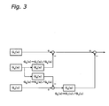
- the transfer function G2(s) of the first vibration detecting load cell 32 is matched with the transfer function G1(s) of the weight detecting load cell 31, and for this purpose, a new transfer function G4(s), which is a ratio between the transfer functions G1(s) and G2(s), is calculated according to a formula in Fig. 3.
- the arithmetic processing for correction is effected on the detection signal of the first vibration detecting load cell 32, and the detection signal thus processed for correction is subtracted from the detection signal of the weight detecting load cell 31. Consequently, the floor vibration components detected by the first vibration detecting load cell 32 are removed from the detection signal obtained by the weight detecting load cell 31, which corresponds to the weight of the object X, floor vibration components and motor vibration components.
- the detection signal, from which the floor vibration components are removed, corresponds to the weight of the object X and the motor vibration components.
- processing is performed to match the transfer functions G2(s) and G3(s) of the load cells 32 and 33 with each other.
- the transfer function G2(s) of the first vibration detecting load cell 32 is matched with the transfer function G3(s) of the second vibration detecting load cell 33, and for this purpose, a new transfer function G5(s), which is a ratio between the transfer functions G3(s) and G2(s), is calculated according to a formula in Fig. 3.
- the arithmetic processing for correction is effected on the detection signal of the first vibration detecting load cell 32, and the detection signal thus processed for correction is subtracted from the detection signal of the second vibration detecting load cell 33. Consequently, the floor vibration components detected by the first vibration detecting load cell 32 are removed from the detection signal obtained by the second vibration detecting load cell 33, which corresponds to the floor vibration components and motor vibration components.
- the detection signal, from which the floor vibration components are removed, corresponds to only the motor vibration components.
- the transfer functions G1(s) and G3(s) of the load cells 31 and 33 are matched with each other for performing the arithmetic processing between the detection signals of the weight detecting load cell 31 and the second vibration detecting load cell 33.
- the transfer function G3(s) of the second vibration detecting load cell 33 is processed to match with the transfer function G1(s) of the weight detecting load cell 31, and for this purpose, a new transfer function G6(s), which is a ratio between the transfer functions G1(s) and G3(s), is calculated according to a formula in Fig. 3.
- the arithmetic processing for correction is effected on the detection signal of the second vibration detecting load cell 33, which has already been processed by the foregoing subtraction processing.
- the detection signal of the second vibration detecting load cell 33 thus processed for correction is subtracted from the detection signal of the weight detecting load cell 31, which has already been processed by the foregoing subtraction processing. Consequently, the detection signal of the second vibration detecting load cell 33, which has been changed by the subtraction processing to the signal corresponding to the motor vibration signal, is subtracted from the detection signal of the weight detecting load cell 31, which has been changed by the subtraction processing to the signal corresponding to the weight of the object X and the motor vibration components. Thereby, the detection signal corresponding to only the weight of the object X is obtained in an isolated form.
- the detection signal of the weight detecting load cell 31, which is arithmetically processed as described above, is supplied to the low-pass filter 45, and is output therefrom after being filtered in a predetermined manner.
- the vibration components on the fixed end side (31a) and the free end side (31b) of the weight detecting load cell 31, i.e., the floor vibration components and the motor vibration components are detected by using the first and second vibration detecting load cells 32 and 33, and then are removed from the detection signal of the weight detecting load cell 31 so that only the signal matching with the weight of the object X is obtained. Thereby, the weight of the object X can be detected with improved precision.
- the arithmetic processing can be appropriately effected for correction on the detection signals. Due to differences between detection targets, restrictions on the installation space and others, the first and second vibration detecting load cells 32 and 33 may be smaller in size than that of weight detecting load cell 31. Even in such cases, the arithmetic processing for correction allows highly precise detection of the weight of the object X.
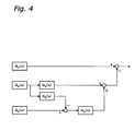
- the floor vibration components are first subtracted from the detection signal of the weight detecting load cell 31, and then the motor vibration components are subtracted.
- the floor vibration components and the motor vibration components are first added together, and then are subtracted from the detection signal of the weight detecting load cell 31.
- the arithmetic processing for correction is effected on the detection signal of the first vibration detecting load cell 32 according to the transfer function G4(s), such that the detection signal of the first vibration detecting load cell 32 can be subtracted from the detection signal of the weight detecting load cell 31.
- the transfer function G6(s) the arithmetic processing for correction is effected on the detection signal of the second vibration detecting load cell 33, which has already been processed by the foregoing subtraction processing, such that the detection signal of the second vibration detecting load cell 33 can be subtracted from the detection signal of the weight detecting load cell 31.
- the detection signals of the first and second vibration detecting load cells 32 and 33 thus processed for correction are added together, and then are subtracted from the detection signal of the weight detecting load cell 31. In this case, only the signal matching with the weight of the object X is obtained so that the weight of the object X can be detected with improved precision.
- various kinds of arithmetic processing are performed with the transfer functions G1(s) - G6(s) for providing a signal matching with the weight of the object X.
- constants may be used instead of the transfer functions G1(s) - G6(s).
- constants may be used as the correction ratios for the arithmetic correction processing of the detection signals of the load cells instead of the transfer functions.
- the low-pass filter 45 is arranged immediately downstream from the arithmetic circuit 44.
- the low-pass filters may be arranged downstream from each of the A/D converters 43 ... 43.
- the weight detecting apparatus removes the influence of the vibration disturbance exerted from the device installation side and the object placing side, and thereby improves the detection precision.
- the invention can be appropriately applied to the field of weight detecting technology in connection with the weight detecting apparatus for precisely detecting the weight of an object placed thereon.
Landscapes
- Physics & Mathematics (AREA)
- General Physics & Mathematics (AREA)
- Electric Ovens (AREA)
- Controlling Sheets Or Webs (AREA)
Abstract
Description
Claims (5)
- A weight detecting apparatus for detecting a weight of an object comprising:weight detecting means having a fixed end kept in a fixed state, and having a free end bearing a weight of the object;first vibration detecting means arranged on a fixed end side of said weight detecting means for detecting a vibration component;second vibration detecting means arranged on a free end side of said weight detecting means for detecting a vibration component; andweight calculating means for calculating the weight of the object based on the detection signals provided from said weight detecting means and said first and second vibration detecting means, by removing the vibration components from the detection signal provided from said weight detecting means.
- The weight detecting apparatus according to claim 1, wherein
said weight calculating means calculates the vibration component on the free end side of said weight detecting means based on the detection signals provided from said first and second vibration detecting means. - The weight detecting apparatus according to claim 1 or 2, wherein
said weight calculating means calculates the weight of the object by performing arithmetic processing for correction on the detection signals provided from said weight detecting means, said first vibration detecting means and said second vibration detecting means, and thereby removing the vibration component on said fixed end side and the vibration component on said free end side from the detection signal of said weight detecting means. - The weight detecting apparatus according to claim 1, 2 or 3, wherein
said weight calculating means has:A/D converters receiving the detection signals provided from said weight detecting means, said first vibration detecting means and said second vibration detecting means respectively,an arithmetic circuit receiving an output signal of said A/D converters, anda low-pass filter receiving an output signal of said arithmetic circuit. - The weight detecting apparatus according to claim 1, 2 or 3, wherein
said weight calculating means has:A/D converters receiving the detection signals provided from said weight detecting means, said first vibration detecting means and said second vibration detecting means respectively,low-pass filters receiving an output signal of said A/D converters, andan arithmetic circuit receiving an output signal of said low-pass filters.
Applications Claiming Priority (3)
| Application Number | Priority Date | Filing Date | Title |
|---|---|---|---|
| JP2003098841A JP3808841B2 (en) | 2003-04-02 | 2003-04-02 | Weight detector |
| JP2003098841 | 2003-04-02 | ||
| PCT/JP2004/004372 WO2004090483A1 (en) | 2003-04-02 | 2004-03-26 | Weight detecting device |
Publications (2)
| Publication Number | Publication Date |
|---|---|
| EP1610106A1 true EP1610106A1 (en) | 2005-12-28 |
| EP1610106A4 EP1610106A4 (en) | 2010-10-06 |
Family
ID=33156684
Family Applications (1)
| Application Number | Title | Priority Date | Filing Date |
|---|---|---|---|
| EP04723844A Withdrawn EP1610106A4 (en) | 2003-04-02 | 2004-03-26 | Weight detecting device |
Country Status (5)
| Country | Link |
|---|---|
| US (1) | US6987227B2 (en) |
| EP (1) | EP1610106A4 (en) |
| JP (1) | JP3808841B2 (en) |
| CN (1) | CN100430700C (en) |
| WO (1) | WO2004090483A1 (en) |
Families Citing this family (19)
| Publication number | Priority date | Publication date | Assignee | Title |
|---|---|---|---|---|
| JP3808841B2 (en) * | 2003-04-02 | 2006-08-16 | 株式会社イシダ | Weight detector |
| JP2007101463A (en) * | 2005-10-07 | 2007-04-19 | Ishida Co Ltd | Weight detector |
| DE102005055754B4 (en) * | 2005-11-21 | 2016-10-20 | Wipotec Wiege- Und Positioniersysteme Gmbh | Recording for the drive unit of a transport device |
| DE102006059261B4 (en) * | 2006-12-15 | 2010-09-09 | Sartorius Ag | Electronic scale with an inclinometer and associated method for signal evaluation |
| KR101014537B1 (en) * | 2008-07-04 | 2011-02-14 | 현대모비스 주식회사 | Passenger detection device of car |
| JP5848880B2 (en) * | 2011-03-30 | 2016-01-27 | アンリツインフィビス株式会社 | Weighing device |
| CN102368043B (en) * | 2011-06-27 | 2013-04-17 | 湖州剑力金属制品有限公司 | Weighing apparatus |
| DE102011078567B4 (en) * | 2011-07-04 | 2014-08-28 | Siemens Aktiengesellschaft | Patient storage device for a medical imaging device, and a medical imaging device with the patient support device |
| CN102651329B (en) * | 2011-09-21 | 2014-08-06 | 北京京东方光电科技有限公司 | Detection method for detecting substrate damage in placing box and placing box |
| DE102011054038A1 (en) * | 2011-09-29 | 2013-04-04 | Krones Ag | Filling device and method for filling containers |
| JP5474130B2 (en) * | 2012-05-31 | 2014-04-16 | 東芝エレベータ株式会社 | Passenger detection device for passenger conveyor |
| US10935416B1 (en) * | 2013-12-18 | 2021-03-02 | Amazon Technologies, Inc. | System for generating compensated weight data using a gyroscope |
| KR101666056B1 (en) * | 2014-12-10 | 2016-10-13 | (주)솔루션아이티 | Scale device for collecting apparatus of food waste for quantity based system and manufacturing method thereof |
| GB2545168A (en) * | 2015-12-01 | 2017-06-14 | D & G Mech Solutions Ltd | An improved conveyer weigh cell module |
| CN105854273A (en) * | 2016-05-12 | 2016-08-17 | 金华杰夫体育用品有限公司 | Electric skateboard safeguard system |
| JP6987451B2 (en) * | 2017-12-20 | 2022-01-05 | 大和製衡株式会社 | Weight sorter |
| US11402257B1 (en) * | 2019-11-21 | 2022-08-02 | Amazon Technologies, Inc. | System for compensation of weight sensor |
| US12624982B2 (en) | 2022-06-02 | 2026-05-12 | Electronic Theatre Controls, Inc. | Intelligent digital load cell transducer |
| EP4459246A1 (en) * | 2023-05-02 | 2024-11-06 | MBP S.r.l. | Weighing device for a multi-head weighing machine, weighing head and multi-head weighing machine |
Family Cites Families (18)
| Publication number | Priority date | Publication date | Assignee | Title |
|---|---|---|---|---|
| FR2123226A1 (en) * | 1971-01-27 | 1972-09-08 | Equip Electro Rech App | |
| EP0122796B1 (en) * | 1983-04-14 | 1989-08-02 | Kabushiki Kaisha Ishida Koki Seisakusho | Weighing apparatus |
| US4593778A (en) * | 1983-06-21 | 1986-06-10 | Kabushiki Kaisha Ishida Koki Seisakusho | Weighing machine with dummy load cell for error correction |
| DD274274A1 (en) * | 1988-07-21 | 1989-12-13 | Univ Rostock | ELECTRIC WEIGHING DEVICE |
| JP3312626B2 (en) * | 1989-12-01 | 2002-08-12 | 株式会社石田衡器製作所 | Load cell type weight measuring device |
| US5172783A (en) * | 1991-07-01 | 1992-12-22 | Pitney Bowes, Inc. | Weighing scale with validating reference channel |
| JP3314107B2 (en) * | 1993-07-22 | 2002-08-12 | 株式会社イシダ | Accelerometer mounting structure |
| JP3539582B2 (en) * | 1993-12-02 | 2004-07-07 | 株式会社イシダ | Multi-point cell type weighing device |
| US5936206A (en) * | 1993-12-31 | 1999-08-10 | Ishida Co., Ltd. | Weighing machines with means for correcting effects of floor vibrations on weight signals therefrom |
| US6034334A (en) * | 1994-04-12 | 2000-03-07 | Ishida Co. Ltd. | Method of and means for correcting effects of floor vibrations on weight signals from a weighing machine |
| JPH08110261A (en) * | 1994-10-11 | 1996-04-30 | Yamato Scale Co Ltd | Mass measuring device and weight measuring device |
| JP3463827B2 (en) | 1994-11-10 | 2003-11-05 | 株式会社イシダ | Transport weighing device |
| DE69624049T2 (en) * | 1995-07-26 | 2003-03-06 | Ishida Co., Ltd. | weighing |
| CN2309563Y (en) * | 1997-09-25 | 1999-03-03 | 武汉利德机电技术有限公司 | High-speed dynamic electronic railroad track scale |
| DE19846769C2 (en) | 1998-10-10 | 2000-08-31 | Sartorius Gmbh | Weight determination device |
| JP4170516B2 (en) * | 1999-05-07 | 2008-10-22 | 大和製衡株式会社 | Weighing device |
| DE10058217B4 (en) * | 2000-11-23 | 2005-06-23 | GFI Gesellschaft für Informationssysteme mbH | Libra |
| JP3808841B2 (en) * | 2003-04-02 | 2006-08-16 | 株式会社イシダ | Weight detector |
-
2003
- 2003-04-02 JP JP2003098841A patent/JP3808841B2/en not_active Expired - Fee Related
-
2004
- 2004-03-26 US US10/516,357 patent/US6987227B2/en not_active Expired - Fee Related
- 2004-03-26 WO PCT/JP2004/004372 patent/WO2004090483A1/en not_active Ceased
- 2004-03-26 EP EP04723844A patent/EP1610106A4/en not_active Withdrawn
- 2004-03-26 CN CNB2004800005688A patent/CN100430700C/en not_active Expired - Fee Related
Also Published As
| Publication number | Publication date |
|---|---|
| WO2004090483A1 (en) | 2004-10-21 |
| EP1610106A4 (en) | 2010-10-06 |
| JP3808841B2 (en) | 2006-08-16 |
| US20050252695A1 (en) | 2005-11-17 |
| CN1697965A (en) | 2005-11-16 |
| CN100430700C (en) | 2008-11-05 |
| US6987227B2 (en) | 2006-01-17 |
| JP2004309148A (en) | 2004-11-04 |
Similar Documents
| Publication | Publication Date | Title |
|---|---|---|
| US6987227B2 (en) | Weight detecting apparatus with vibrational sensors attached to both the free end and the fixed end of the load cell | |
| CA2997068C (en) | A vibration detection and cancellation circuit | |
| JP3312626B2 (en) | Load cell type weight measuring device | |
| JP3128072B2 (en) | Weight measuring device | |
| EP0711983B1 (en) | Conveyor-mounted weighing apparatus | |
| US20100161268A1 (en) | Device for vibration compensation of the weight signal of a weighing sensor | |
| US6786093B2 (en) | Balancing apparatus | |
| JP5848880B2 (en) | Weighing device | |
| US7190134B2 (en) | Torsional vibration suppressing method and apparatus in electric motor speed control system | |
| US4926359A (en) | Weight sensing apparatus | |
| US5340950A (en) | Method and apparatus for weighing objects | |
| CN102269912B (en) | Optical apparatus having image shake correcting function | |
| JP2022171927A (en) | Weighing device | |
| JP2009287930A (en) | Substrate observing device and substrate polishing device | |
| EP0464223A1 (en) | Weight measuring apparatus | |
| US5656800A (en) | Accurate and responsive weighing apparatus with drift compensation | |
| JP3765105B2 (en) | Floor vibration correction method and apparatus | |
| JP3429374B2 (en) | Weighing device | |
| CN224151807U (en) | Dynamic weighing body capable of carrying out transportation | |
| JP2608229B2 (en) | Weight measuring device | |
| JP2022144132A (en) | Weighing device | |
| JP5554188B2 (en) | Weighing conveyor device | |
| SU1348680A1 (en) | Method of separating correction planes in adjustment of balancing machine | |
| JPH07167706A (en) | Floor vibration correction method and apparatus | |
| JP3179862B2 (en) | Signal processing circuit of weighing device |
Legal Events
| Date | Code | Title | Description |
|---|---|---|---|
| PUAI | Public reference made under article 153(3) epc to a published international application that has entered the european phase |
Free format text: ORIGINAL CODE: 0009012 |
|
| 17P | Request for examination filed |
Effective date: 20041220 |
|
| AK | Designated contracting states |
Kind code of ref document: A1 Designated state(s): AT BE BG CH CY CZ DE DK EE ES FI FR GB GR HU IE IT LI LU MC NL PL PT RO SE SI SK TR |
|
| AX | Request for extension of the european patent |
Extension state: AL LT LV MK |
|
| DAX | Request for extension of the european patent (deleted) | ||
| RBV | Designated contracting states (corrected) |
Designated state(s): DE FR GB IT |
|
| A4 | Supplementary search report drawn up and despatched |
Effective date: 20100903 |
|
| 17Q | First examination report despatched |
Effective date: 20111118 |
|
| STAA | Information on the status of an ep patent application or granted ep patent |
Free format text: STATUS: THE APPLICATION IS DEEMED TO BE WITHDRAWN |
|
| 18D | Application deemed to be withdrawn |
Effective date: 20141001 |