EP1609561A2 - Method for manufacturing a mounting assembly consisting of a sheet plate and a functional element attached at said sheet plate, sheet plate and functional element, - Google Patents
Method for manufacturing a mounting assembly consisting of a sheet plate and a functional element attached at said sheet plate, sheet plate and functional element, Download PDFInfo
- Publication number
- EP1609561A2 EP1609561A2 EP05013265A EP05013265A EP1609561A2 EP 1609561 A2 EP1609561 A2 EP 1609561A2 EP 05013265 A EP05013265 A EP 05013265A EP 05013265 A EP05013265 A EP 05013265A EP 1609561 A2 EP1609561 A2 EP 1609561A2
- Authority
- EP
- European Patent Office
- Prior art keywords
- sheet metal
- metal part
- functional element
- areas
- sheet
- Prior art date
- Legal status (The legal status is an assumption and is not a legal conclusion. Google has not performed a legal analysis and makes no representation as to the accuracy of the status listed.)
- Granted
Links
- 238000000034 method Methods 0.000 title claims description 58
- 238000004519 manufacturing process Methods 0.000 title claims description 12
- 229910052751 metal Inorganic materials 0.000 claims abstract description 231
- 239000002184 metal Substances 0.000 claims abstract description 231
- 239000000463 material Substances 0.000 claims description 59
- 238000004049 embossing Methods 0.000 claims description 49
- 230000000295 complement effect Effects 0.000 claims description 18
- 238000002360 preparation method Methods 0.000 claims description 17
- 238000004080 punching Methods 0.000 claims description 16
- 230000008569 process Effects 0.000 claims description 15
- 230000007704 transition Effects 0.000 claims description 13
- 230000015572 biosynthetic process Effects 0.000 claims description 12
- 238000007493 shaping process Methods 0.000 claims description 9
- 238000013459 approach Methods 0.000 claims description 7
- 238000002788 crimping Methods 0.000 claims description 2
- 230000037431 insertion Effects 0.000 abstract 1
- 238000003780 insertion Methods 0.000 abstract 1
- 239000011324 bead Substances 0.000 description 10
- 239000000853 adhesive Substances 0.000 description 5
- 230000001070 adhesive effect Effects 0.000 description 5
- 230000008901 benefit Effects 0.000 description 5
- 210000003128 head Anatomy 0.000 description 5
- 238000012549 training Methods 0.000 description 5
- 230000000694 effects Effects 0.000 description 3
- 238000003825 pressing Methods 0.000 description 3
- 229910000831 Steel Inorganic materials 0.000 description 2
- 230000009471 action Effects 0.000 description 2
- 229910045601 alloy Inorganic materials 0.000 description 2
- 239000000956 alloy Substances 0.000 description 2
- 229910052782 aluminium Inorganic materials 0.000 description 2
- XAGFODPZIPBFFR-UHFFFAOYSA-N aluminium Chemical compound [Al] XAGFODPZIPBFFR-UHFFFAOYSA-N 0.000 description 2
- 230000008859 change Effects 0.000 description 2
- 238000005520 cutting process Methods 0.000 description 2
- 238000013461 design Methods 0.000 description 2
- 239000011159 matrix material Substances 0.000 description 2
- 210000001331 nose Anatomy 0.000 description 2
- 239000010959 steel Substances 0.000 description 2
- 229910000838 Al alloy Inorganic materials 0.000 description 1
- 101001108245 Cavia porcellus Neuronal pentraxin-2 Proteins 0.000 description 1
- FYYHWMGAXLPEAU-UHFFFAOYSA-N Magnesium Chemical compound [Mg] FYYHWMGAXLPEAU-UHFFFAOYSA-N 0.000 description 1
- 229910000861 Mg alloy Inorganic materials 0.000 description 1
- 230000006835 compression Effects 0.000 description 1
- 238000007906 compression Methods 0.000 description 1
- 238000007596 consolidation process Methods 0.000 description 1
- 238000009826 distribution Methods 0.000 description 1
- 238000010438 heat treatment Methods 0.000 description 1
- 238000005304 joining Methods 0.000 description 1
- 229910052749 magnesium Inorganic materials 0.000 description 1
- 239000011777 magnesium Substances 0.000 description 1
- 239000007769 metal material Substances 0.000 description 1
- 230000002093 peripheral effect Effects 0.000 description 1
- 239000007787 solid Substances 0.000 description 1
- 238000003860 storage Methods 0.000 description 1
- 238000005482 strain hardening Methods 0.000 description 1
Images


Classifications
-
- B—PERFORMING OPERATIONS; TRANSPORTING
- B23—MACHINE TOOLS; METAL-WORKING NOT OTHERWISE PROVIDED FOR
- B23P—METAL-WORKING NOT OTHERWISE PROVIDED FOR; COMBINED OPERATIONS; UNIVERSAL MACHINE TOOLS
- B23P19/00—Machines for simply fitting together or separating metal parts or objects, or metal and non-metal parts, whether or not involving some deformation; Tools or devices therefor so far as not provided for in other classes
- B23P19/04—Machines for simply fitting together or separating metal parts or objects, or metal and non-metal parts, whether or not involving some deformation; Tools or devices therefor so far as not provided for in other classes for assembling or disassembling parts
- B23P19/06—Screw or nut setting or loosening machines
- B23P19/062—Pierce nut setting machines
-
- Y—GENERAL TAGGING OF NEW TECHNOLOGICAL DEVELOPMENTS; GENERAL TAGGING OF CROSS-SECTIONAL TECHNOLOGIES SPANNING OVER SEVERAL SECTIONS OF THE IPC; TECHNICAL SUBJECTS COVERED BY FORMER USPC CROSS-REFERENCE ART COLLECTIONS [XRACs] AND DIGESTS
- Y10—TECHNICAL SUBJECTS COVERED BY FORMER USPC
- Y10T—TECHNICAL SUBJECTS COVERED BY FORMER US CLASSIFICATION
- Y10T29/00—Metal working
- Y10T29/49—Method of mechanical manufacture
- Y10T29/49826—Assembling or joining
- Y10T29/49908—Joining by deforming
- Y10T29/49936—Surface interlocking
-
- Y—GENERAL TAGGING OF NEW TECHNOLOGICAL DEVELOPMENTS; GENERAL TAGGING OF CROSS-SECTIONAL TECHNOLOGIES SPANNING OVER SEVERAL SECTIONS OF THE IPC; TECHNICAL SUBJECTS COVERED BY FORMER USPC CROSS-REFERENCE ART COLLECTIONS [XRACs] AND DIGESTS
- Y10—TECHNICAL SUBJECTS COVERED BY FORMER USPC
- Y10T—TECHNICAL SUBJECTS COVERED BY FORMER US CLASSIFICATION
- Y10T29/00—Metal working
- Y10T29/49—Method of mechanical manufacture
- Y10T29/49826—Assembling or joining
- Y10T29/49908—Joining by deforming
- Y10T29/49938—Radially expanding part in cavity, aperture, or hollow body
- Y10T29/4994—Radially expanding internal tube
-
- Y—GENERAL TAGGING OF NEW TECHNOLOGICAL DEVELOPMENTS; GENERAL TAGGING OF CROSS-SECTIONAL TECHNOLOGIES SPANNING OVER SEVERAL SECTIONS OF THE IPC; TECHNICAL SUBJECTS COVERED BY FORMER USPC CROSS-REFERENCE ART COLLECTIONS [XRACs] AND DIGESTS
- Y10—TECHNICAL SUBJECTS COVERED BY FORMER USPC
- Y10T—TECHNICAL SUBJECTS COVERED BY FORMER US CLASSIFICATION
- Y10T29/00—Metal working
- Y10T29/49—Method of mechanical manufacture
- Y10T29/49826—Assembling or joining
- Y10T29/49908—Joining by deforming
- Y10T29/49938—Radially expanding part in cavity, aperture, or hollow body
- Y10T29/49943—Riveting
-
- Y—GENERAL TAGGING OF NEW TECHNOLOGICAL DEVELOPMENTS; GENERAL TAGGING OF CROSS-SECTIONAL TECHNOLOGIES SPANNING OVER SEVERAL SECTIONS OF THE IPC; TECHNICAL SUBJECTS COVERED BY FORMER USPC CROSS-REFERENCE ART COLLECTIONS [XRACs] AND DIGESTS
- Y10—TECHNICAL SUBJECTS COVERED BY FORMER USPC
- Y10T—TECHNICAL SUBJECTS COVERED BY FORMER US CLASSIFICATION
- Y10T29/00—Metal working
- Y10T29/49—Method of mechanical manufacture
- Y10T29/49826—Assembling or joining
- Y10T29/49947—Assembling or joining by applying separate fastener
- Y10T29/49954—Fastener deformed after application
- Y10T29/49956—Riveting
-
- Y—GENERAL TAGGING OF NEW TECHNOLOGICAL DEVELOPMENTS; GENERAL TAGGING OF CROSS-SECTIONAL TECHNOLOGIES SPANNING OVER SEVERAL SECTIONS OF THE IPC; TECHNICAL SUBJECTS COVERED BY FORMER USPC CROSS-REFERENCE ART COLLECTIONS [XRACs] AND DIGESTS
- Y10—TECHNICAL SUBJECTS COVERED BY FORMER USPC
- Y10T—TECHNICAL SUBJECTS COVERED BY FORMER US CLASSIFICATION
- Y10T403/00—Joints and connections
- Y10T403/49—Member deformed in situ
- Y10T403/4941—Deformation occurs simultaneously with action of separate, diverse function, joint component
-
- Y—GENERAL TAGGING OF NEW TECHNOLOGICAL DEVELOPMENTS; GENERAL TAGGING OF CROSS-SECTIONAL TECHNOLOGIES SPANNING OVER SEVERAL SECTIONS OF THE IPC; TECHNICAL SUBJECTS COVERED BY FORMER USPC CROSS-REFERENCE ART COLLECTIONS [XRACs] AND DIGESTS
- Y10—TECHNICAL SUBJECTS COVERED BY FORMER USPC
- Y10T—TECHNICAL SUBJECTS COVERED BY FORMER US CLASSIFICATION
- Y10T403/00—Joints and connections
- Y10T403/49—Member deformed in situ
- Y10T403/4966—Deformation occurs simultaneously with assembly
-
- Y—GENERAL TAGGING OF NEW TECHNOLOGICAL DEVELOPMENTS; GENERAL TAGGING OF CROSS-SECTIONAL TECHNOLOGIES SPANNING OVER SEVERAL SECTIONS OF THE IPC; TECHNICAL SUBJECTS COVERED BY FORMER USPC CROSS-REFERENCE ART COLLECTIONS [XRACs] AND DIGESTS
- Y10—TECHNICAL SUBJECTS COVERED BY FORMER USPC
- Y10T—TECHNICAL SUBJECTS COVERED BY FORMER US CLASSIFICATION
- Y10T403/00—Joints and connections
- Y10T403/49—Member deformed in situ
- Y10T403/4974—Member deformed in situ by piercing
Definitions
- the sequence of relatively raised or recessed areas may assume the most diverse concrete forms.
- the intermediate areas are preferably larger in area the recessed areas and raised areas each have an area at least substantially parallel to a respective one this entering into contact area of the functional element is, whereby the surface pressure on the functional element when attaching the functional element occurs on the sheet metal part in this area, below the critical Value is, so that here no pronounced change in shape of Function element occurs.
- Such an embodiment also leads to the desired toothing between the functional element and the Sheet metal part.
- Fig. 7 shows a Shaping the individual raised areas 16 and recessed areas 18 corresponding to FIGS. 6A to 6C, but in this example two elevated area 16 are arranged side by side and this of two recessed areas 18 and these in turn from two elevated areas 16 and so on.
- the raised areas 16 and the recessed areas 18 each have the same contour.
- 9 shows an embossment 14, in which two raised areas 16 with a shape corresponding to the elevated areas 16 of FIG. 4A next to each other, from an intermediate region 17 with approximately the shape of the intermediate region 17 of Fig. 4A, which then in a recessed area 18th merges, which formed according to the recessed areas 18 of Fig. 6A is.
- This recessed area 18 is then from another intermediate area 17 followed, in turn, by two elevated areas 16 etc. is followed.
- Another possibility would be for example one Provide kind of corrugation where relatively narrow valleys and mountains side by side present on a cone surface such as 22.
- the sheet preparation is a plan view in at least substantially circular elevation in the sheet metal part by means of a correspondingly shaped Stamp and a complementary die made in the center of the elevation a hole 13 with a hole edge 52 is generated.
- the sheet surface approaches via a convex curve 54 the hole edge 52, wherein the embossing 14 is provided in the region of this convex curve.
- the sheet preparation is made so that the convex curve 54 in an in a plane parallel to the local sheet plane 56 outside the survey lying annular surface 58 passes.
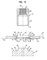
- the rivet bead 26 of FIG. 14 is replaced by using the die 70 of FIG Fig. 13 by crimping the originally cylindrical rivet section 24 of the functional element 12 by about 90 °, relative to the middle Longitudinal axis 36 of the functional element 12 and the hole 13 generated.
- Result has the free end 72 of the rivet portion after training of the rivet bead in the direction radially outward.
- the die 70 of FIG. 13 has a central post 74 with a End face 76 which is rounded at the peripheral edge 78. From the rounded Circumferential edge 78, starting from the middle post 74 diverges slightly away in the direction of the front 76 and goes into a rounded Ring depression 80 over which surrounds the post. The outer boundary edge 82 of the ring recess then goes over a tilted Ring shoulder in a flat annular surface 84 of the die over, with the plane Ring surface is perpendicular to the longitudinal axis 36.
- the rivet section 12 which has an outer diameter, which corresponds to the punch hole 13 (but also slightly smaller or may be larger) by a not shown setting head by the Hole 13 in the sheet metal part and pressed on the post of the die, thereby making the rounded end 72 of the rivet portion of the post 74 light is extended and then in the region of the rounded depression 80th is deflected by 90 ° or slightly more than 90 °.
- the matrix is from the bottom Tool of a press or supported by an intermediate plate of the press, while the setting head from the intermediate plate of the press or from an upper tool of the press is worn.
- the embossment 14 may be completely absent, e.g. then, if it is the functional element is a ball pin, for example according to the EP application 01989624.0, where no rotation is necessary or can be sufficiently ensured by friction.
- the functional element a body part 25 with a tubular or cylindrical formed thereon Rivet portion as 12 in FIG. 13 and the sheet metal part 10, as in Fig.
- the inventive method can not only be used with steel sheets but also with other types of metal, for example Aluminum sheets, or with magnesium sheets.
- the material of the functional element is then chosen normally adjusted and it come for the fasteners all materials in question, which are common today.
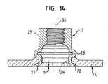
- the present invention also includes an assembly part from a sheet metal part and a functional element, wherein the Functional element a body part 25 with a trained thereon tubular or cylindrical rivet section 24 and the sheet metal part 10, a plan view in at least substantially circular elevation 72, wherein in the middle of the elevation a hole 13 with a hole edge 52 is present and on the opposite side of the survey the Sheet surface has a recess and a convex, concave or inclined surface approaches the edge of the hole, with the particular Characteristic that the free end 72 of the rivet section 24 to a Nietbördel 26 is formed, facing away from the survey 50 Side of the sheet metal part is present that the rivet section 24 on the survey Sampled 50 side of the sheet metal part to a ring fold 28 squeezed is that of the sheet metal part 10 in the area of the survey 50 between clamps itself and the Nietbördel 26 and that the Nietbördel 26 on the elevation opposite side of the sheet metal part does not have the local level 56 of the sheet metal part protrudes around the survey around
- the functional element for non-rotatably attachment to a sheet metal part in particular to a sheet metal part according to one of claims 12 to 34 or 32 to 36, for example by means of the method according to one of the claims 1 to 11 or 24 to 31, may be an element having rivet features or equipped with punching and riveting features or with Einpressermkmalen is, however, in the field of attachment to the sheet metal part before attachment has no own anti-rotation features.
Abstract
Description
Die vorliegender Erfindung betrifft ein Verfahren zur Herstellung eines Zusammenbauteils bestehend aus einem Blechteil und einem an diesem durch einen Nietvorgang oder durch einen Niet- und Stanzvorgang oder durch einen Einpressvorgang angebrachten Funktionselement, wobei das Blechteil im Bereich der Anbringung des Funktionselements mit einer Prägung vorgesehen ist. Ferner betrifft die Erfindung ein Blechteil sowie ein Funktionselement, die zur Anwendung in dem Verfahren geeignet sind.The present invention relates to a method for producing a component assembly consisting of a sheet metal part and one on this by a riveting or by a riveting and punching process or by a press-fitting attached functional element, wherein the Sheet metal part in the region of attachment of the functional element with a Embossing is provided. Furthermore, the invention relates to a sheet metal part as well a functional element suitable for use in the process are.
Ein Verfahren der eingangs genannten Art ist aus dem europäischen Patent 0 539 793 bekannt und wird dort mit einem Funktionselement in Form einer Nietmutter beschrieben. Dort wird ein Blechteil mit einer Prägung in Form eines ringförmigen Kragens um ein vorgestanztes Loch vorgesehen und der zylindrische Nietabschnitt des Funktionselements wird von der Seite des über die Ebene des Blechteils vorstehenden Ringkragens in das Stanzloch hineingeführt, so dass eine ringförmige Auflagefläche des Funktionselements, die den Übergang zwischen dem Körper des Mutterelements und dem zylindrischen Nietteil bildet, zur Anlage an der Stirnseite des ringförmigen Kragens kommt. Dreieckige nasenförmige Verdrehsicherungsrippen sind im Übergangsbereich zwischen der ringförmigen Anlagefläche und dem zylindrischen Nietabschnitt vorgesehen. Anschließend wird das Mutterelement so gegen das Blechteil gepresst, dass mittels einer unterhalb des Blechteils angeordneten Matrize der zylindrische Nietabschnitt zu einem Nietbördel umgeformt und gleichzeitig der ringförmige Kragen, der eine konusförmige Gestalt aufweist, zumindest teilweise flach gepresst wird. Hierdurch wird der Durchmesser des Stanzlochs verkleinert und gleichzeitig der Außendurchmesser des Nietabschnitts vergrößert, so dass ein erheblicher "Würgegriff" zwischen dem Blechteil und dem Mutterelement um den Nietabschnitt herum erfolgt. Ferner werden die Verdrehsicherungsnasen in das Blechmaterial des Blechteils hinein gepresst und sorgen für eine ausgezeichnete Verdrehsicherung.A method of the type mentioned is from the European patent 0 539 793 and is there with a functional element in Form described a rivet nut. There is a sheet metal part with an embossing provided in the form of an annular collar around a pre-punched hole and the cylindrical rivet portion of the functional element becomes from the side of the over the plane of the sheet metal part projecting annular collar led into the punched hole, so that an annular bearing surface of the Functional element representing the transition between the body of the nut element and the cylindrical rivet part forms, to rest against the front side the annular collar comes. Triangular nose-shaped anti-rotation ribs are in the transition area between the annular contact surface and the cylindrical rivet section. Subsequently the nut member is pressed against the sheet metal part that by means of a below the sheet metal part arranged die of the cylindrical rivet section transformed into a Nietbördel and at the same time the annular Collar, which has a conical shape, at least partially flat is pressed. As a result, the diameter of the punch hole is reduced and at the same time increases the outer diameter of the rivet, so that a significant "stranglehold" between the sheet metal part and the nut member done around the rivet section. Furthermore, the anti-rotation lugs pressed into the sheet material of the sheet metal part and ensure an excellent security against rotation.
Ein verwandtes Verfahren wird auch zur Anbringung von so genannten RND-Elementen (europäisches Patent 11116891) an Blechteilen verwendet.A related method is also used for attaching so-called RND elements (European patent 11116891) used on sheet metal parts.
Es handelt sich bei den Befestigungselementen gemäß dem europäischen
Patent 0 539 793 und EP 11116891 um so genannte Nietelemente, die in
vorgestanzte Löcher im Blechteil eingesetzt werden und am Blechteil
durch einen Nietvorgang befestigt werden. Es ist allerdings nicht zwingend
erforderlich, das Blech vorzulochen, sondern es gibt auch Befestigungselemente,
die mit einem Blechteil vernietet werden, ohne dass der Nietabschnitt
des Elements das Blechteil durchdringt. Dies ist beispielsweise bei
dem Nietelement gemäß EP-A-0 993 902 der Fall. Ferner gibt es Funktionselemente,
die durch einen so genannten Niet- und Stanzvorgang an
einem Blechteil angebracht werden. In diese Kategorie fallen beispielsweise
die SBF-Bolzenelemente der Fa. Profil-Verbindungstechnik GmbH & Co
KG, die in der deutschen Patentschrift 34 47 006 beschrieben sind bzw.
die entsprechenden Mutterelemente, die mit einem ähnlichen Verfahren
an einem Blechteil angebracht werden. Allerdings wird bei diesen Elementen
das Blechteil vor der Anbringung nicht mit einer Vorprägung versehen,
sondern die Prägung des Blechteils erfolgt bei der Anbringung des
Funktionselements in einem ersten Stadium des Anbringungsverfahrens.It concerns with the fasteners according to the European
Patent 0 539 793 and EP 11116891 to so-called rivet elements, which in
Pre-punched holes are used in the sheet metal part and on the sheet metal part
be fastened by a riveting operation. It is not mandatory
required to pre-punch the sheet, but there are also fasteners,
which are riveted with a sheet metal part without the rivet section
of the element penetrates the sheet metal part. This is for example
the rivet element according to EP-A-0 993 902 the case. There are also functional elements
by a so-called riveting and punching process
be attached to a sheet metal part. For example, fall into this category
the SBF bolt elements from the company Profil-Verbindungstechnik GmbH & Co
KG, which are described in
Ferner sind im Stand der Technik so genannte Einpresselemente bekannt, die in ein Blechteil eingepresst werden, und zwar derart, dass das Blechteil um das Element herum gewissermaßen fließt und zu einer formschlüssigen Verhakung des Elements mit dem Blechteil führt, ohne dass ein eigentlicher Nietvorgang stattfindet. Ein Beispiel für ein solches Einpresselement bzw. einen Einpressvorgang ist das so genannte EBF-Element der Fa. Profil-Verbindungstechnik GmbH & Co KG, das zusammen mit dem Verfahren zu dessen Anbringung im europäischen Patent 0 678 679 B bzw. in der späteren europäischen Patentschrift EP-B-0958100 beschrieben ist. Die letztgenannte europäische Patentschrift beschreibt außerdem eine Möglichkeit, ein EBF-Element selbststanzend in ein Blechteil einzubringen. Auch die oben als Nietelemente bezeichneten RND-Elemente können selbststanzend in Blechteile eingebracht werden, selbst wenn dies nicht häufig praktiziert wird.Furthermore, so-called press-in elements are known in the prior art, which are pressed into a sheet metal part, in such a way that the sheet metal part flows around the element and flows to a form-fitting Entanglement of the element with the sheet metal part leads without an actual riveting process takes place. An example of such a press-in element or a press-fitting process is the so-called EBF element the company Profil-Verbindungstechnik GmbH & Co KG, the together with the method for its attachment in the European patent 0 678 679 B or in the later European patent EP-B-0958100 is described. The latter European patent describes also a possibility of self-stamping an EBF element in to introduce a sheet metal part. Also referred to above as rivet elements RND elements can be self-piercing in sheet metal parts, even if this is not practiced frequently.
Die Bezeichnung Funktionselement ist aber nicht auf Befestigungselemente beschränkt, sondern gilt im Fachbereich als Bezeichnung für eine Vielzahl anderer Elemente, die bestimmte Funktionen erfüllen und welche durch Nietvorgänge, durch Stanz- und Nietvorgänge oder durch Einpressvorgänge an Blechteilen befestigt werden können. Beispielsweise beschreibt die oben genannte EP-B-1202834 unter anderem ein Funktionselement, das mit einem Stanz- und Nietvorgang an einem Blechteil befestigt wird, wobei eine Realisierung des entsprechenden Elements in Form eines so genannten Kugelbolzens erfolgt. Das entsprechende Element ist in der europäischen Patentanmeldung EP-A-01989624.0 beschrieben, wobei der Kugelkopf dieses Elements dazu dient, eine Kugelpfanne aufzunehmen, um beispielsweise als Gasdämpferabstützung für eine Motorhaube oder Heckklappe verwendet zu werden. Ferner sind Funktionselemente bekannt, die als Zapfen für die Lagerung von drehbaren Teilen dienen oder beispielsweise mit einer Klippaufnahme vorgesehen sind, die für die Klippbefestigung von Teppichen, Bremsleitungen oder Kabelbäumen in Pkws dienen. Ferner sind Funktionselemente mit einer tannenbaumartigen Struktur bekannt, die für untergeordnete Befestigungszwecke verwenden werden können in Zusammenarbeit mit Hohlteilen, die auf die Tannenbaumstruktur aufgedrückt werden.The term functional element is not on fasteners limited, but is in the department as a name for a variety other elements that perform certain functions and which by riveting operations, by punching and riveting operations or by pressing operations can be attached to sheet metal parts. For example, describes the above-mentioned EP-B-1202834, inter alia, a functional element, attached to a sheet metal part with a punching and riveting operation is, with a realization of the corresponding element in the form a so-called ball stud takes place. The corresponding element is in European Patent Application EP-A-01989624.0, wherein the ball head of this element serves to receive a ball socket, for example, as a gas damper support for a hood or tailgate to be used. Furthermore, functional elements known, which serve as a pin for the storage of rotating parts or provided for example with a clip recording, the for the clip fixing of carpets, brake lines or wiring harnesses in Cars serve. Furthermore, functional elements with a fir-tree-like Structure known to use for subordinate attachment purposes can be made in cooperation with hollow parts on the Fir tree structure are pressed.
Mit den obigen Erläuterungen soll klargestellt werden, dass die vorliegende Erfindung bei einer Vielzahl von verschiedenen Funktionselementen und bei einer Vielzahl an sich bekannter Anbringungstechniken verwenden werden kann.The above explanations are intended to clarify that the present Invention in a variety of different functional elements and use in a variety of per se known mounting techniques can be.
Bei vielen bekannten Funktionselementen besteht die Notwendigkeit, das jeweilige Element verdrehsicher an das Blechteil anzubringen. Zwar kann eine gewisse Verdrehsicherung durch die so genannte Lochlaibung erreicht werden, d.h. die Verdrehsicherung, die durch Reibungskräfte zwischen dem Blechteil und dem Funktionselement entstehen, doch meistens wird das Funktionselement mit Verdrehsicherungsmerkmalen, beispielsweise in Form von Rippen und/oder Nuten, in einem Bereich, der bei Herstellung der Verbindung zwischen dem Blechteil und dem Funktionselement in Berührung mit dem Blechteil gelangt, versehen. Solche Merkmale am Funktionselement führen zu komplementären Formen am Blechteil und es wird eine Art Verzahnung zwischen dem Funktionselement und dem Blechteil erreicht, die die Verdrehsicherung sicherstellt. Auch ist es bekannt, zur Erzeugung der Verdrehsicherung oder zur Steigerung des Verdrehwiderstandes einen Klebstoff im Fügebereich zwischen dem Blechteil und dem Funktionselement zu verwenden. In many known functional elements, there is a need to To install each element against rotation of the sheet metal part. Although can achieved a certain anti-rotation through the so-called Lochlaibung are, i. the anti-rotation, caused by frictional forces between the sheet metal part and the functional element arise, but mostly is the functional element with anti-rotation features, for example in the form of ribs and / or grooves, in an area of manufacture the connection between the sheet metal part and the functional element comes into contact with the sheet metal part, provided. Such features on the functional element lead to complementary shapes on the sheet metal part and there is a kind of gearing between the functional element and reaches the sheet metal part, which ensures the rotation. It is too known, for generating the rotation or to increase the Verdrehwiderstandes an adhesive in the joining region between the sheet metal part and to use the functional element.
Aufgabe der vorliegenden Erfindung ist es, ein Verfahren der eingangs genannten Art weiterzubilden, so dass eine Verdrehsicherung zwischen dem Blechteil und dem Funktionselement auf eine neue Art und Weise zustande kommt, die auch genutzt werden kann, um Herstellungsvorteile zu erreichen.Object of the present invention is a method of the aforementioned To develop further, so that a rotation between the Sheet metal part and the functional element in a new way which can also be used to achieve manufacturing advantages.
Zur Lösung dieser Aufgabe wird verfahrensmäßig ein Verfahren der eingangs genannten Art vorgesehen, dass sich dadurch auszeichnet, dass die Prägung vor Anbringung des Funktionselements hergestellt wird und aus einer Folge von relativ zueinander erhöhten und vertieften Bereichen besteht und dass bei Anbringung des Funktionselements dieses gegen das Blechteil derart gedrückt wird, dass die Prägung des Blechteils zu einer komplementären Formgebung des Funktionselements im Bereich des Funktionselements führt, der mit der Prägung in Anlage kommt.To solve this problem is procedurally a method of the initially provided that it is characterized in that the Embossing is made prior to attachment of the functional element and off a sequence of relatively raised and recessed areas and that when attaching the functional element of this against the Sheet metal part is pressed so that the embossing of the sheet metal part to a complementary shaping of the functional element in the region of Function element that comes into contact with the embossing.
In entsprechender Weise zeichnet sich ein erfindungsgemäßes Blechteil dadurch aus, dass die Prägung vor Anbringung des Funktionselements herstellt wird und aus einer Folge von relativ zueinander erhöhten und vertieften Bereichen besteht.In a corresponding manner, a sheet metal part according to the invention is distinguished characterized in that the embossing prior to attachment of the functional element is produced and increased from a sequence of relative to each other and deepened areas.
Der Erfindungsgedanke ist daher darin zu sehen, dass anstatt Verdrehsicherungsmerkmale am Funktionselement vorzusehen eine besondere Art der Prägung des Blechteils vorgenommen wird, so dass die Verdrehsicherungsmerkmale sozusagen am Blechteil vorgesehen sind. Die Prägung des Blechteils führt dann bei Anbringung des Funktionselements zu einer komplementären Formgebung des Funktionselements im Bereich des Funktionselements, der mit der Prägung in Anlage kommt. Hierdurch entsteht eine Art Verzahnung zwischen dem Funktionselement und dem Blechteil, die die notwendige Verdrehsicherung sicherstellt. Es ist allerdings auch möglich, die erfindungsgemäße Prägung des Blechteils auch mit einem Funktionselement zu verwenden, das über eigene Verdrehsicherungsmerkmale verfügt.The inventive concept is therefore to be seen in that instead of anti-rotation features to provide the functional element a special kind the embossing of the sheet metal part is made so that the anti-rotation features are provided on the sheet metal part, so to speak. The coinage of the Sheet metal part then leads to the attachment of the functional element to a complementary shaping of the functional element in the region of Functional element that comes into contact with the embossing. This results a kind of toothing between the functional element and the Sheet metal part, which ensures the necessary anti-rotation. It is, however also possible, the embossing of the sheet metal part according to the invention also to use with a functional element that has its own anti-rotation features features.
Es ist zunächst überraschend, dass es auf diese Weise gelingt, eine Verdrehsicherung oder eine ergänzende Verdrehsicherung zustande zu bringen. In der Vergangenheit wurde davon ausgegangen, dass die Funktionselemente aus einem Material mit einer im Vergleich zum Blechteil höheren Festigkeit bestehen, wodurch der Gedanke nicht vorhanden war, dass das weichere Blechmaterial ausgeprägte Abdrücke im härteren Material des Funktionselements erzeugen könnte. Es hat sich aber überraschender Weise herausgestellt, dass genau dies der Fall ist. Der Erfolg dieser Methode mag etwas damit zu tun haben, dass durch die Prägung des Blechteils dieses eine Art Kaltbefestigung erfährt, wodurch die Härte des Blechteils, d.h. die Festigkeit des Blechteils, im Vergleich zum Funktionselement gesteigert wird, selbst wenn sie den Festigkeitswert des Funktionselements noch nicht erreicht. Es mag auch etwas damit zu tun haben, dass die Verdrehsicherungsmerkmale lokal zu hohen Flächenpressungen am Funktionselement führen, die bei der dynamischen Anbringung eines Funktionselements ausreichen, um die komplementäre Form der Prägung am Funktionselement zu erzeugen.It is initially surprising that it succeeds in this way, a rotation or to bring about a supplementary anti-twist device. In the past, it was assumed that the functional elements made of a material with a higher compared to the sheet metal part Strength exist, whereby the thought did not exist that the softer sheet material pronounced imprints in the harder material of the Could generate functional element. It has become more surprising Way out, that's exactly the case. The success of this method may have something to do with that by the stamping of the sheet metal part this undergoes a kind of cold fixation, whereby the hardness of the sheet metal part, i.e. the strength of the sheet metal part, compared to the functional element is increased, even if they the strength value of the functional element not reached yet. It may also have something to do with it that the anti-rotation features locally to high surface pressures lead to the functional element that in the dynamic attachment of a Functional element sufficient to the complementary shape of the embossing to generate on the functional element.
Ausgehend von dieser Situation wurde es dem Anmelder klar, dass, wenn diese Vorgehensweise mit Blechteilen gelingt, die im Vergleich zum Funktionselement eine geringere Festigkeit aufweisen, es um so eher mit höherfesten Blechen, die zunehmend in gewissen technischen Bereichen, vor allem im Automobilbau verwendet werden, gelingen müsste. Diese Erkenntnis führt auch zu dem Ergebnis, dass es bei Verwendung von höherfesten Blechen nicht unbedingt notwendig ist, Funktionselemente zu verwenden, die eine im Vergleich zum Blechmaterial höhere Festigkeit aufweisen. In vielen Fällen können somit Befestigungselemente sogar mit Vorteil verwendet werden, die eine geringere Festigkeit als die des Blechmaterials aufweisen. Dies spart bei Herstellung der Funktionselemente nicht nur den Einsatz von eher teureren Materialien, sondern erspart darüber hinaus auch kostspielige Herstellungsschritte, wie etwa die Wärmebehandlung der für die Funktionselemente verwendeten Materialien. Die Möglichkeit, Materialien für Befestigungselemente zu verwenden, die eine im Vergleich zum Blechmaterial geringere Festigkeit aufweisen, ermöglicht es, Schraubbefestigungen zu verwenden, die im Bezug auf Bruchdehnung oder Ermüdungserscheinungen weniger kritisch sind.Based on this situation, it became clear to the applicant that if this approach succeeds with sheet metal parts, compared to the functional element have a lower strength, the higher the higher Sheet metal, which is increasingly in certain technical fields, in front be used in the automotive industry, would have to succeed. This realization also leads to the conclusion that it is using higher-strength Sheet metal is not absolutely necessary to use functional elements which have a higher strength compared to the sheet material. In many cases, so fasteners can even with Advantage be used, which has a lower strength than that of the sheet material exhibit. This saves on production of the functional elements not only the use of more expensive materials, but saves on it In addition, costly manufacturing steps, such as the heat treatment the materials used for the functional elements. The Possibility to use materials for fasteners that have a compared to the sheet material lower strength allowed to use screw fixings related to breaking elongation or fatigue are less critical.
Es gelingt bei entsprechender Bemessung der Anlagefläche des Funktionselements auch, eine Art der Anbringung zu erreichen, bei der die zulässige Flächenpressung im Bereich der Anlagefläche des Funktionselements nicht überschritten wird, und zwar selbst dann nicht, wenn höherfestes Blech verwendet wird.It succeeds with appropriate dimensioning of the contact surface of the functional element Also, to achieve a kind of attachment in which the permissible Surface pressure in the area of the contact surface of the functional element is not exceeded, even if not higher-strength Sheet metal is used.
Ein besonderer Vorteil der Erfindung ist darin zu sehen, dass die bisher für notwendig erachteten Verdrehsicherungsmerkmale am Funktionselement entweder vollständig weggelassen werden können oder durch wenige, leichter herzustellende Verdrehsicherungsmerkmale ersetzt werden können, da die besondere Prägung des Blechteils zu einer deutlichen Steigerung der Verdrehsicherungswerte führt oder vollständig zur Sicherstellung der erforderlichen Verdrehsicherung ausreichen. Durch das Weglassen der bisherigen Verdrehsicherungsmerkmale am Funktionselement bzw. durch die Vereinfachung der Verdrehsicherungsmerkmale können Kosten bei der Herstellung der Funktionselemente eingespart werden, da die entsprechenden Werkzeuge, häufig Kaltschlagwerkzeuge, dann weniger Verschleiß unterliegen bzw. eine weniger kritische Formgebung erhalten. Zwar müssen die Werkzeuge zur Prägung des Blechteils entsprechend komplizierter ausgelegt werden - im Vergleich zu einer Prägung in Form eines Ringkragens ohne vertiefte oder erhöhte Bereiche - die Zusatzkosten sind jedoch durchaus erträglich, zumal die Prägung üblicherweise in einer Herstellungsstufe des Blechteils in einer ohnehin vorhandenen Presse erfolgt, während bei Herstellung eines Funktionselements mit Kaltschlagwerkzeugen mehrere formgebende Herstellungsschritte erforderlich sind, so dass eine entsprechend große Anzahl von Kaltschlagwerkzeugen im Spiel sind.A particular advantage of the invention is the fact that the previously deemed necessary anti-rotation features on the functional element either completely omitted or by a few, be replaced easier to be manufactured anti-rotation features can, as the special embossing of the sheet metal part to a significant increase the anti-rotation values leads or completely to ensure suffice the required anti-rotation. By omitting the previous anti-rotation features on the functional element or by simplifying the anti-rotation features Cost savings in the production of functional elements, since the appropriate tools, often cold cutting tools, then less Wear subject or receive a less critical shape. Although the tools for embossing the sheet metal part accordingly be designed more complicated - compared to an embossing in shape a ring collar without recessed or elevated areas - the additional cost However, they are quite tolerable, especially since the coinage is usually in one Production stage of the sheet metal part takes place in an already existing press, during manufacture of a functional element with cold impact tools several shaping manufacturing steps are required, so that a correspondingly large number of cold cutting tools in the Game are.
Die Folge von relativ zueinander erhöhten oder vertieften Bereichen wird üblicherweise ringförmig ausgeführt, kann aber polygonförmig, beispielsweise rechteckig oder quadratisch sein, wenn die Querschnittsform des Funktionselement dies erfordert oder sinnvoll macht. Ferner könnte die Folge auch linear sein, wenn das erfindungsgemäße Verfahren zur Anbringung von rechteckigen Elementen verwendet wird, die beispielsweise nur an zwei Längsbereichen oder -kanten eine Verdrehsicherung erfordern. Mit anderen Worten kann die Erfindung ohne weiteres auch mit solchen rechteckigen oder quadratischen Funktionselementen verwendet werden, selbst wenn die Folge nicht die Form eines geschlossenen Rings aufweist.The result of relatively elevated or recessed areas becomes Usually designed annular, but can be polygonal, for example be rectangular or square if the cross sectional shape of the Functional element requires or makes sense. Furthermore, the Sequence also be linear when the inventive method of attachment is used by rectangular elements, for example only require an anti-rotation device on two longitudinal areas or edges. In other words, the invention can readily with such rectangular or square functional elements used even if the episode does not take the form of a closed ring having.
Die Folge von relativ zueinander erhöhten oder vertieften Bereichen kann die verschiedensten konkreten Formen annehmen.The sequence of relatively raised or recessed areas may assume the most diverse concrete forms.
Bei einer ersten erfindungsgemäßen Variante besteht die Folge aus erhöhten Bereichen, die zu Vertiefungen im Funktionselement führen und aus gegenüber den erhöhten Bereichen vertieften Flächenbereichen, die zumindest im Wesentlichen zu keiner Verformung der Funktionselemente führen. Dabei können die vertieften Bereiche flächenmäßig größer sein als die erhöhten Bereiche und/oder jeweils eine Fläche aufweisen, die zumindest im Wesentlichen parallel zu einem jeweiligen mit dieser in Anlage tretenden Bereich des Funktionselement liegt. Dagegen können die erhöhten Bereiche gerundete oder spitz zulaufende Scheitel aufweisen. Sie können in Draufsicht kreisrund, oval, polygonal, länglich oder anderweitig geformt ausgebildet werden.In a first variant according to the invention, the sequence consists of elevated Areas that lead to depressions in the functional element and off opposite the raised areas recessed surface areas, at least essentially no deformation of the functional elements to lead. The recessed areas may be larger in area than the raised areas and / or each having a surface which, at least essentially parallel to a respective one coming into contact with this Area of the functional element is located. In contrast, the increased Areas have rounded or tapered apex. You can in plan view circular, oval, polygonal, oblong or otherwise shaped be formed.
Bei einer Ausbildung der vertieften Bereiche jeweils mit einer Fläche, die zumindest im Wesentlichen parallel zu einem jeweiligen mit dieser in Anlage tretenden Bereich des Funktionselements liegt, kann sichergestellt werden, dass die Flächenpressungskräfte, die dort auf das Funktionselement einwirken, unterhalb des kritischen Werts liegen, bei dem eine Verformung des Funktionselements in diesem Bereich vorkommt. Dagegen können in den erhöhten Bereichen der Prägung, d.h. im Bereich der gerundeten oder spitz zulaufenden Scheitel, durchaus Flächenpressungswerte auftreten, die zu einer komplementären Formgebung des Funktionselements führen und hierdurch zu der oben erwähnten Verzahnung zwischen dem Funktionselement und dem Blechteil führen, die zur Sicherstellung der Verdrehsicherung erforderlich ist. Zwar kann es sein, dass die erhöhten Bereiche der Prägung durch das Anbringen des Funktionselements selbst verformt werden, dennoch führt es zu einer entsprechenden Verformung des Funktionselements, so dass die erwünschte Verzahnung erreicht wird. Natürlich muss das Material des Funktionselements, das im Bereich der erhöhten Bereiche der Prägung verdrängt wird, irgendwohin fließen. Eine Möglichkeit dies zu gewährleisten, besteht darin, die Formgebung des Funktionselements so zu wählen, dass Bereiche vorhanden sind, wo das verdrängte Material hin fließen kann, ohne dass dies negativ auf das so entstehende Zusammenbauteil wirkt. Schließlich kann es auch durchaus vorkommen, dass das verdrängte Material in einen Bereich gelangt, der den vertieften Bereichen der Prägung gegenüber liegt. In an education of recessed areas each with an area that at least substantially parallel to a respective one with this in Appendix passing area of the functional element is ensured be that the surface pressure forces there on the functional element act below the critical value at which a deformation the functional element occurs in this area. On the other hand can in the raised areas of the embossing, i. in the area of the rounded or pointed apex, quite surface pressure values occur, leading to a complementary shaping of the functional element lead and thereby to the above-mentioned gearing lead between the functional element and the sheet metal part to ensure the rotation is required. While it may be that the raised areas of the embossing by the attachment of the functional element even deformed, yet it leads to a corresponding Deformation of the functional element, so that the desired toothing is reached. Of course, the material of the functional element, which is displaced in the area of the raised areas of the embossing, flow somewhere. One way to ensure this is to to choose the shape of the functional element so that areas are present where the displaced material can flow without this has a negative effect on the resulting component assembly. After all It can also happen that the repressed material in one Area opposite to the recessed areas of the coinage lies.
Ferner besteht die Möglichkeit, dass die Folge aus erhöhten Bereichen, die zu Vertiefungen im Funktionselement führen, und aus gegenüber der erhöhten Bereichen vertieften Bereichen besteht, die zu Erhöhungen am Funktionselement führen.There is also the possibility that the consequence of elevated areas, the lead to depressions in the functional element, and from compared to the elevated Areas of in-depth areas leading to increases in Lead functional element.
Bei dieser Ausführungsform kann das Material des Funktionselements, das durch die erhöhten Bereiche der Prägung verdrängt wird, in Erhöhungen am Funktionselement fließen, die den vertieften Bereichen der Prägung gegenüber liegen. Auch diese Ausführung führt somit zu einer ausgeprägten Verzahnung zwischen dem Funktionselement und dem Blechteil.In this embodiment, the material of the functional element, which is displaced by the raised areas of the imprint, in elevations Flow on the functional element that the recessed areas of the embossing lie opposite. This embodiment also leads to a pronounced Gearing between the functional element and the sheet metal part.
Eine weitere Möglichkeit besteht darin, dass die Folge aus vertieften Bereichen besteht, die zu Erhöhungen am Funktionselement führen und aus gegenüber den vertieften Bereichen erhöhten Flächenbereichen besteht, die zumindest im Wesentlichen zu keiner Verformung am Funktionselement führen. Bei dieser Ausführungsform wird davon ausgegangen, dass durch die erheblichen Anbringungskräfte, die auf das Funktionselement ausgeübt werden, Material des Befestigungselements plastisch in die Bereiche fließen kann, die den vertieften Bereichen der Prägung gegenüber liegen und auf diese Weise für die erwünschte Verzahnung zwischen dem Funktionselement und dem Blechteil führen. Die Flächen der erhöhten Bereiche können wie bisher erläutert jeweils mit einer Fläche ausgestattet werden, die zumindest im Wesentlichen parallel zu einem jeweiligen mit dieser in Anlage tretenden Bereich des Funktionselements liegt und die so groß bemessen ist, dass eine Flächenpressung entsteht, die unter dem kritischen Wert liegt, so dass eher kein Material aus diesen Bereichen verdrängt wird. Es bestünde aber auch die Möglichkeit, die Flächen so zu bemessen, dass von hier aus doch Material in Bereiche des Funktionselements fließt, die den vertieften Bereichen der Prägung gegenüber liegen. Another possibility is that the consequence of recessed areas exists that lead to increases in the functional element and off there are increased areas compared to the recessed areas, the at least substantially no deformation on the functional element to lead. In this embodiment, it is assumed that by the considerable attachment forces acting on the functional element be exercised, material of the fastener plastic in the areas can flow towards the recessed areas of the coinage lie and in this way for the desired interlocking between the Guide functional element and the sheet metal part. The surfaces of the raised Areas can be equipped with a surface as previously explained be at least substantially parallel to a respective one this coming into contact area of the functional element is and so is large, that creates a surface pressure, which under the critical value, so rather no material displaced from these areas becomes. But it would also be possible, the surfaces so too measure that material from here into areas of the functional element flowing, which lie opposite the recessed areas of the coinage.
Eine andere Möglichkeit besteht darin, dass die Folge aus erhöhten Bereichen, die zu Vertiefungen im Funktionselement führen und aus gegenüber den erhöhten Bereichen vertieften Bereichen, die zu Erhöhungen am Funktionselement führen besteht sowie aus Zwischenbereichen, die zumindest im Wesentlichen zu keiner Verformung am Funktionselement führen. Bei dieser Ausführungsform können die erhöhten Bereiche eine gerundete oder spitz zulaufende konvexe Form und die vertieften Bereiche eine gerundete oder spitz zulaufende konkave Form aufweisen.Another possibility is that the consequence of elevated areas, leading to depressions in the functional element and from opposite the raised areas recessed areas leading to increases in the Function element lead consists as well as intermediate areas, at least essentially no deformation on the functional element to lead. In this embodiment, the raised portions may be one rounded or tapered convex shape and the recessed areas have a rounded or tapered concave shape.
Dagegen sind die Zwischenbereiche flächenmäßig vorzugsweise größer als die vertieften Bereiche und die erhöhten Bereiche weisen jeweils eine Fläche auf, die zumindest im Wesentlichen parallel zu einem jeweiligen mit dieser in Anlage tretenden Bereich des Funktionselement liegt, wodurch die Flächenpressung, die am Funktionselement bei Anbringung des Funktionselements am Blechteil in diesem Bereich auftritt, unterhalb des kritischen Wertes liegt, so dass hier keine ausgeprägte Formänderung des Funktionselements auftritt. Auch eine solche Ausführungsform führt zu der gewünschten Verzahnung zwischen dem Funktionselement und dem Blechteil.In contrast, the intermediate areas are preferably larger in area the recessed areas and raised areas each have an area at least substantially parallel to a respective one this entering into contact area of the functional element is, whereby the surface pressure on the functional element when attaching the functional element occurs on the sheet metal part in this area, below the critical Value is, so that here no pronounced change in shape of Function element occurs. Such an embodiment also leads to the desired toothing between the functional element and the Sheet metal part.
Es ist keinesfalls erforderlich, dass die Folge aus abwechselnd angeordneten Erhöhungen und Vertiefungen bzw. aus Erhöhungen, Zwischenbereichen und Vertiefungen usw. besteht, sondern es können beliebige Kombinationen zum Einsatz gelangen, beispielsweise kann eine Erhöhung von zwei Vertiefungen gefolgt werden und erst dann erfolgt eine weitere Erhöhung oder es können abwechselnd eine Vertiefung und ein Zwischenbereich zwischen zwei jeweils benachbart angeordneten erhöhten Bereichen vorliegen. Üblicherweise ergibt sich durch die konkret gewählte Anordnung eine sich periodisch wiederholende Folge von Erhöhungen und Vertiefungen bzw. von Erhöhungen, Zwischenbereichen und Vertiefungen bei der Prägung des Blechteils. Dies ist aber nicht zwangsläufig der Fall.It is by no means necessary that the sequence be arranged alternately Elevations and depressions or from elevations, intermediate areas and depressions, etc., but there may be any combinations can be used, for example, an increase of two wells are followed and only then is another increase or alternately a depression and an intermediate region between two respectively adjacent elevated areas available. Usually results from the specific arrangement selected a periodically repeating sequence of peaks and valleys or of elevations, intermediate areas and depressions the embossing of the sheet metal part. But this is not necessarily the case.
Besonders bevorzugte Varianten des erfindungsgemäßen Verfahrens bzw. des erfindungsgemäßen Blechteils sowie des Funktionselements, die zur verdrehsicheren Anbringung an ein Blechteil, insbesondere an ein erfindungsgemäßes Blechteil unter Anwendung des erfindungsgemäßen Verfahrens vorgesehen sind, ergeben sich aus den weiteren Patentansprüchen sowie aus der nachfolgenden Beschreibung bevorzugter Ausführungsbeispiele der Erfindung.Particularly preferred variants of the method or of the sheet metal part according to the invention as well as the functional element, the torsionally secure attachment to a sheet metal part, in particular to an inventive Sheet metal part using the method according to the invention are provided, resulting from the other claims as well as from the following description of preferred embodiments the invention.
Solche bevorzugten Ausführungsbeispiele der Erfindung werden nachfolgend anhand der Zeichnungen näher erläutert, in welcher zeigen:
- Fig. 1A-1D
- ein erfindungsgemäß vorbereitetes Blechteil in einer Draufsicht (Fig. 1A), eine Schnittzeichnung (Fig. 1B nach der Schnittebene IB-IB der Fig. 1A) und in zwei perspektivischen Darstellungen von oben (Fig. 1C) und von unten (Fig. 1D),
- Fig.2A-2B
- die Anbringung eines Funktionselement entsprechend dem europäischen Patent EP 1202834 B1 auf dem vorbereiteten Blechteil der Fig. 1A-1D,
- Fig. 3A-3E
- eine alternative erfindungsgemäße Blechvorbereitung in einer Draufsicht, in zwei Schnittzeichnungen sowie in zwei perspektivischen Darstellungen von oben bzw. von unten,
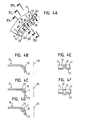
- Fig. 4A-4F
- eine weitere erfindungsgemäße Blechvorbereitung in einer Draufsicht auf einen Teilbereich des Blechs benachbart zu einem Lochrand und in fünf verschiedenen Schnittzeichnungen,
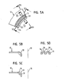
- Fig. 5A-5D
- eine weitere alternative erfindungsgemäße Blechvorbereitung in einer Draufsicht auf einen Teilbereich des Blechs benachbart zu einem Lochrand und in drei verschiedenen Schnittzeichnungen,
- Fig. 6A-6C
- eine weitere alternative erfindungsgemäße Blechvorbereitung in einer Draufsicht auf einen Teilbereich des Blechs benachbart zu einem Lochrand und in zwei verschiedenen Schnittzeichnungen,
- Fig. 7
- eine weitere Alternative einer erfindungsgemäßen Blechvorbereitung, jedoch nur von einem Teilbereich des Randes eines Stanzloches,
- Fig. 8
- eine Darstellung ähnlich der Fig. 7, jedoch mit einer anderen erfindungsgemäßen Blechvorbereitung,
- Fig. 9
- eine weitere Zeichnung ähnlich der Fig. 7, jedoch von einer noch weiteren erfindungsgemäßen Blechvorbereitung,
- Fig. 10
- eine Schnittzeichnung zur Darstellung einer erfindungsgemäßen Blechvorbereitung auf der Oberseite eines Blechteils im Bereich des Lochrandes,
- Fig. 11
- eine Darstellung ähnlich der Fig. 10, jedoch von einem Blechteil mit konusförmigen, nach oben stehenden Rand um ein Stanzloch herum,
- Fig. 12
- eine weitere Schnittzeichnung einer erfindungsgemäßen Blechvorbereitung, wobei die Blechvorbereitung im Bereich eines konusförmigen Ringkragens vorliegt,
- Fig. 13
- eine schematische Darstellung in einem Längsschnitt durch eine andere Ausführungsform des erfindungsgemäßen Verfahrens mit einem Funktionselement, mit einem vorbereiteten Blechteil und mit einer Matrize zur Anbringung des Funktionselementes am Blechteil, und
- Fig. 14
- eine Schnittdarstellung des Zusammenbauteils, das sich durch Anbringung des Funktionselementes der Figur 13 an das dort gezeigte Blechteil ergibt.
- Fig. 1A-1D
- 1A in a plan view (FIG. 1A), a sectional drawing (FIG. 1B according to the sectional plane IB-IB of FIG. 1A) and in two perspective views from above (FIG. 1C) and from below (FIG. 1D) .
- 2A-2B
- the attachment of a functional element according to the European patent EP 1202834 B1 on the prepared sheet metal part of FIGS. 1A-1D,
- Figs. 3A-3E
- an alternative sheet preparation according to the invention in a plan view, in two sectional drawings and in two perspective views from above or from below,
- Figs. 4A-4F
- a further sheet preparation according to the invention in a plan view of a portion of the sheet adjacent to a hole edge and in five different sectional drawings,
- Figs. 5A-5D
- a further alternative inventive sheet preparation in a plan view of a portion of the sheet adjacent to a hole edge and in three different sectional drawings,
- Figs. 6A-6C
- a further alternative inventive sheet preparation in a plan view of a portion of the sheet adjacent to a hole edge and in two different sectional drawings,
- Fig. 7
- a further alternative of a sheet metal preparation according to the invention, but only of a partial region of the edge of a punched hole,
- Fig. 8
- a representation similar to FIG. 7, but with another sheet preparation according to the invention,
- Fig. 9
- 7 is a further drawing similar to FIG. 7, but of a still further sheet preparation according to the invention, FIG.
- Fig. 10
- 1 is a sectional view showing a sheet metal preparation according to the invention on the upper side of a sheet metal part in the region of the hole edge,
- Fig. 11
- 10, but of a sheet metal part with a cone-shaped, upstanding edge around a punching hole around,
- Fig. 12
- 1 is a further sectional view of a sheet metal preparation according to the invention, wherein the sheet preparation is present in the region of a cone-shaped annular collar,
- Fig. 13
- a schematic representation in a longitudinal section through another embodiment of the method according to the invention with a functional element, with a prepared sheet metal part and with a die for mounting the functional element on the sheet metal part, and
- Fig. 14
- a sectional view of the assembly part, which results from attaching the functional element of Figure 13 to the sheet metal part shown there.
Die Fig. 1A bis 1D zeigen in verschiedenen Darstellungen ein Blechteil 10
zur Verwendung mit einem an diesem durch einen Nietvorgang oder durch
einen Niet- und Stanzvorgang angebrachten Funktionselement 12 (Fig. 2A
und 2B), wobei das Bauteil 10 im Bereich der Anbringung des Funktionselements
mit einer Prägung 14 vorgesehen ist. Diese vor der Anbringung
des Funktionselements hergestellte Prägung 14 besteht aus einer Folge
von relativ zueinander erhöhten und vertieften Bereichen 16 bzw. 18. Die
Folge 15 ist hier ringförmig dargestellt, könnte aber bei Bedarf, falls die
Form des Funktionselements dies erfordert, polygonförmig, beispielsweise
rechteckig oder quadratisch sein.FIGS. 1A to 1D show a sheet-
Die Prägung 14 wird so ausgeführt, dass ein Ringkragen 20 aus Blechmaterial
entsteht und die Folge 15 im Bereich des Übergangs 22 des Blechmaterials
in den Ringkragen 20 ausgebildet wird. Genauer gesagt wird die
Prägung 14 im Bereich der radial inneren Seite der konusförmigen Vertiefung
24 im Blech, d.h. der entsprechenden konusförmigen Ringfläche 22
durch Anwendung eines (nicht gezeigten) Stempels ausgebildet mit einer
zu der Form der Prägung komplementären Form, wobei das Blechteil während
der Ausbildung der Prägung auf einer entsprechenden Matrize (nicht
gezeigt) abgestützt wird. Dabei kann der Ringkragen in einer ersten Stufe
ohne Prägung ausgebildet und die Prägung erst anschließend vorgesehen
werden oder diese kann gleichzeitig mit der Herstellung des Ringkragens
in einer Stufe hergestellt werden.The
Die Figuren 2A und 2B zeigen anschließend die Anbringung des Funktionselements
12 auf das vorbereitete Blechteil 10. Es handelt sich bei dem
Funktionselement 12 um das Element, das im Detail im europäischen Patent
EP 1202834 B 1 beschrieben und beansprucht wird. In dieser europäischen
Patentschrift wird das Element 12 benutzt, um das Blechteil 10 zu
durchstanzen, wobei ein Ringkragen ähnlich dem Ringkragen 20 im
Blechteil während der Durchstanzung des Blechteils durch das Funktionselement
12 entsteht, da das Blechteil auf einer Matrize mit einer entsprechenden
Ringvertiefung abgestützt ist. Danach wird das Material des
Nietabschnitts 24 am unteren Ende des Funktionselements 12 durch den
gerundeten Boden der Ringvertiefung in der Matrize nach außen in einen
Rollkragen um den Ringkragen 28 herum geführt, um ein Nietbördel auszubilden,
wie bei 26 in Fig. 2B gezeigt. D.h. der Ringkragen 20 ist von einer
ringförmigen Nut aufgenommen, die durch die Verformung des unteren
Endes des Nietabschnitts 24 des Funktionselements 12 entstanden
ist. Ferner wird in der EP-B-1202834 wie auch hier gezeigt, das Material
des ringförmigen Nietabschnitts 24 oberhalb des Blechteils zu einem Ringfalz
gestaucht, wie bei 28 in Fig. 2B gezeigt. Dies führt dazu, dass das Material
des Blechteils 10 im Randbereich des Stanzlochs 21 in einer Art
Ringaufnahme des verformten Nietabschnitts des Funktionselements 12
eingeklemmt wird. Figures 2A and 2B then show the attachment of the
Im Gegensatz zu dem in der EP-B-1202834 beschriebenen Verfahrens
wird hier das Funktionselement 12 durch das vorgestanzte Loch 21 im
Blechteil 10 geführt. Die Matrize, die bei der Anbringung des Funktionselements
12 verwendet wird, hat aber eine Form entsprechend der Form
der Matrize nach der EP-B-1202834 und das Funktionselement 12 wird
genauso von oben auf das Blechteil und die Matrize zu gedrückt, wie in
der EP-B-1202834 beschrieben. Allerdings ist es bei der vorliegenden Erfindung
nicht zwingend erforderlich die Matrize mit Nuten oder Nasen im
Bereich des Stempelansatzes bzw. des Übergangs von der ringförmigen
Vertiefung in der Stirnseite vorzusehen, um eine Verdrehsicherung zu erreichen,
da diese Funktion durch die erfindungsgemäße Blechvorbereitung
erreicht wird.In contrast to the method described in EP-B-1202834
Here is the
Bei den Ausführungsformen, die in der EP-B-1202834 B1 beschrieben werden, kommen entweder keine Verdrehsicherungsmerkmale zum Einsatz oder es werden kleinere Verdrehsicherungsmerkmale wie Rillen oder Nasen im Bereich des das Nietbördel bildenden Bereichs des Funktionselements vorgesehen. Alternativ dazu wird in der EP-B-1202834 erwähnt, dass sich radial erstreckende Nasen entweder in der Matrize zur Ausbildung des Nietbördels und/oder in der Stirnfläche des den Ringfalz bildenden Stempels vorgesehen werden, die dann auch zu einer gegenseitigen Verformung des Blechteils und des anliegenden Bereichs des Nietbördels und/oder des Ringfalzes führen, die der Erhöhung der Verdrehsicherheit dienen.In the embodiments described in EP-B-1202834 B1 Either no anti-rotation features are used or there are smaller anti-rotation features such as grooves or Noses in the region of the Nietbördel forming portion of the functional element intended. Alternatively, it is mentioned in EP-B-1202834, that radially extending tabs either in the die for training the Nietbördels and / or in the end face of the annular fold forming Stamps are provided, which then also to a mutual Deformation of the sheet metal part and the adjoining area of the rivet bead and / or the Ringfalzes lead, increasing the security against rotation serve.
Im Falle des vorliegenden Verfahrens wird die Verdrehsicherung anderweitig
erreicht, und zwar einerseits durch die Prägung des Blechteils, die vor
Anbringung des Funktionselements hergestellt wird und aus der Folge 15
von relativ zueinander erhöhten und vertieften Bereichen 16 bzw. 18 besteht
und andererseits, dass bei Anbringung des Funktionselements 12
dieses gegen das Blechteil derart gedrückt wird, dass die Prägung 14 des
Blechteils 10 zu einer komplementären Formgebung des Funktionselements
im Bereich des Funktionselements führt, der mit der Prägung in
Anlage kommt, d.h. im Bereich der Unterseite des Ringfalzes 28. Zwar ist
die Ebene der Schnittzeichnung in Fig. 2B so gewählt, dass man nicht erkennen
kann, dass das Material des Ringfalzes 28 in den vertieften Bereichen
18 der Prägung eingeflossen ist, es versteht sich aber, dass bei der
Anbringung des Funktionselements die erheblichen Quetschkräfte, die auf
den Ringfalz 28 wirken, dass dort vorhandene Blechmaterial dazu bringt,
in die Vertiefungen 18 hinein zu fließen, wodurch eine Verzahnung zwischen
dem Funktionselement 12 und dem Blechteil 10 entsteht, die eine
erhebliche Verdrehsicherung bietet, d.h. einen entsprechenden Verdrehwiderstand
erzeugt.In the case of the present method, the rotation is different
achieved, on the one hand by the embossing of the sheet metal part, the front
Attachment of the functional element is manufactured and from the sequence 15th
consists of relatively raised and recessed
Bei der Anbringung des Funktionselements 12 werden, wie in der EP-B-1202834
beschrieben, zunächst über einen inneren Stempel (nicht gezeigt)
Kräfte auf die obere Stirnseite 30 des Funktionselements 12 ausgeübt,
die ausreichen, um den Nietbördel auszubilden und den Ringfalz 28
vorzuformen. Diese Kräfte führen nicht zu einer Verformung des Gewindes
des Funktionselements 12, da der Bereich des Funktionselements 12 mit
Gewinde 23 wesentlich dicker ausgebildet ist als der zylinderförmige Nietabschnitt
24, so dass nur der Bereich 24 verformt wird. Im letzten Stadium
des Anbringungsverfahrens wird der Ringfalz 28 flach gepresst, d.h.
noch weiter hinuntergedrückt als in Fig. 2B bezeigt, und zwar mittels eines
rohrförmigen Außenstempels 32, der, wie ebenfalls in der EP-B-1202834
beschrieben, sich synchron mit dem nicht gezeigten Innenstempel
bewegt, und dessen untere Stirnfläche direkt auf die Oberseite 34 des
Ringfalzes 28 drückt, so dass die Verformungskräfte lediglich im Bereich
des Nietabschnitts 24 des Funktionselements zwischen dem zylindrischen
Außenstempel 32 und der unterhalb des Nietbördels vorgesehenen Matrize
zur Wirkung kommen und für das entsprechende Fließverhalten des
Materials des Nietabschnitts 24 in die Vertiefungen 18 hinein sorgt.When attaching the
Konkret besteht die Folge 15 in diesem Beispiel aus den vertieften Bereichen
18, die zu Erhöhungen am Funktionselement, d.h. im unteren Bereich
des Ringfalzes 28 in Fig. 2B, und aus gegenüber den vertieften Bereichen
erhöhte Flächenbereiche 16, die zumindest im Wesentlichen zu
keiner Verformung am Funktionselement 12 im Bereich des Ringfalzes
führen.Concretely, the
Der Grund, warum in diesem Beispiel die erhöhten Bereiche 16 zu keiner
(nennenswerten) Verformung im Bereich des Ringfalzes 28 führen, hat im
Prinzip zwei Ursachen. Als erstes sind die erhöhten Bereiche 16 flächenmäßig
deutlich größer als die vertieften Bereiche 18, so dass dort die Flächenpressungskräfte,
die zur Wirkung gelangen, deutlich niedriger sind
und unterhalb des Wertes liegen, der zu einer Verformung des Materials
des Ringfalzes führen würde. Zum zweiten liegen die Flächenbereiche 16
bei der Ausbildung des Ringfalzes 28 zumindest im Wesentlichen parallel
zu der lokalen Oberfläche des Ringfalzes im Bereich dieser Flächenbereiche
16, wodurch eine gleichmäßige Druckverteilung auftritt, die auch dazu
beiträgt, die Kompressionskräfte, die auf das Blechmaterials einerseits
und auf das Material des Nietabschnitts 24 andererseits wirken, in einem
Bereich zu halten, die zu keiner nennenswerten Verformung führen. Die
Lage ist natürlich bei den Vertiefungen 18 anders, da das Material des
Nietabschnitts erst bei Vollendung der Anbringung des Funktionselements
am Blechteil vollflächig an die konkaven Vertiefungen 18 zur Anlage gelangt.The reason why in this example the raised
Eine andere grundlegende Art der Blechvorbereitung, d.h. der Ausbildung der Prägung, kommt auch in Frage und wird anschließend anhand der Fig. 3A bis 3E näher erläutert. Es werden für Teile, die Teilen der bisherigen Figuren entsprechen, die gleichen Bezugszeichen verwendet. Auch die bisherige Beschreibung gilt für die entsprechenden Teile bzw. Merkmale, sofern nichts Gegenteiliges gesagt wird. Dies gilt auch für die weitere Beschreibung.Another basic type of sheet preparation, i. the education of the coinage, is also in question and is subsequently based on the Fig. 3A to 3E explained in more detail. It will be for parts that are part of the previous ones Figures correspond to the same reference numerals. Also the previous description applies to the corresponding parts or features, Unless otherwise stated. This also applies to the further description.
Im Beispiel der Fig. 3A bis 3E besteht die Folge 15 aus erhöhten Bereichen
16, die zu Vertiefungen im Funktionselement führen, und aus gegenüber
den erhöhten Bereichen vertieften Flächenbereichen 18, die zumindest
im Wesentlichen zu keiner Verformung am Funktionselement 12
führen.In the example of FIGS. 3A to 3E, the
Wie aus den Fig. 3A bis 3E ersichtlich, haben die erhöhten Bereiche 16 in
diesem Beispiel die gleiche Kontur wie die vertieften Bereiche 18 bei den
Ausführungsformen der Fig. 1A-1D bzw. Fig. 2A. In entsprechender Weise
haben die vertieften Bereiche 18 in diesem Beispiel die gleiche Kontur wie
die erhöhten Bereiche 16 bei der bisherigen Ausführungsform. Die konvexe
Form der erhöhten Bereiche 16 ist in diesem Beispiel besonders deutlich
an der Schnittzeichnung gemäß Fig. 3C (Schnittebene IIIC-IIIC der
Fig. 3A) zu sehen, wo die gerundete Form leicht zu sehen ist.As can be seen in FIGS. 3A to 3E, the raised
Das Verfahren zur Anbringung eines Funktionselements an das Blechteil
10 gemäß Fig. 3A bis 3E läuft genauso ab, wie im Zusammenhang mit den
Fig. 2A, 2B beschrieben, mit der Ausnahme, dass jetzt die erhabenen,
konvexen Bereiche 16 der Prägung 14 entsprechende Vertiefungen in der
Unterseite des Ringfalzes 28 des Funktionselements 12 bei dessen Anbringung
bilden, während die flächenmäßig größeren Bereiche 18 auch
hier zu keiner wesentlichen Verformung am Funktionselement führen. The method for attaching a functional element to the
Die Wirkung der erhabenen Bereiche 16 bei der Ausbildung von Vertiefungen
in der Unterseite des Ringfalzes 28 ist auch deshalb ausgeprägt,
weil die erhöhten Bereiche 16 zunächst nur über eine kleine Fläche auf
das Material des Funktionselements, d.h. auf das Material des Nietabschnitts
24 des Funktionselements bei der Ausbildung des Ringfalzes 28
wirken, so dass dort eine hohe Flächenpressung vorliegt, die die Ausbildung
der Vertiefungen und der Verhakung zwischen dem Funktionselement
und dem Blechmaterial begünstigt. Auch hier liegen die flächenmäßig
größeren Bereiche 18 beim Abschluss des Anbringungsverfahrens im
Wesentlichen parallel zu der lokalen Oberfläche des Ringfalzes 28 des
Funktionselements 12, so dass auch aus diesem Grunde dort die Flächenpressung
eher gering ist und keine Verformung des Funktionselements
zu befürchten ist.The effect of the raised
Es werden nunmehr einige weitere Beispiele einer erfindungsgemäße Blechvorbereitung beschrieben.There will now be some further examples of an inventive Sheet metal preparation described.
Um die zeichnerische Darstellung zu vereinfachen, wird in Fig. 4A das
Blechteil 10 nur in einem Randbereich des Stanzlochs 13 gezeigt und das
Blechteil wird nicht im gesamten Umriss gezeigt. Es ist aber aus Fig. 4A
zu erkennen, dass die Grundform des Blechteils mit Ringkragen 20 und
mit der Prägung 14 im Bereich des Übergangs von der Oberseite des
Blechteils in den Ringkragen gleich gestaltet ist wie bei den bisherigen
Ausführungsbeispielen. In diesem Beispiel sind die erhöhten Bereiche 16
und die vertieften Bereiche 18 abwechselnd auf der konusförmigen Ringfläche
22 vorgesehen, und zwar mit einem erheblichen Abstand zwischen
den einzelnen Erhöhungen und Vertiefungen, die Zwischenbereiche 17
bilden. Es ist anzumerken, dass hier die erhöhten Bereiche 16 und die
vertieften Bereiche 18 anstatt eine eher runde Kontur wie bisher eine eher
längliche Kontur aufweisen, jedoch selbst von konvexer bzw. konkaver
Form sind, wie beispielsweise aus den Fig. 4E und 4F hervorgeht.In order to simplify the drawing, in Fig. 4A the
Es ist auch anzumerken, dass die Schnittzeichnung der Fig. 4B entsprechend
der Schnittlinie IVB-IVB der Fig. 4A, die Schnittzeichnung gemäß
Fig. 4C entsprechend der Schnittebene IVC-IVC der Fig. 4A und die
Schnittzeichnung der Fig. 4D entsprechend der Schnittebene IVD-IVD der
Fig. 4A gezeichnet ist. Dagegen entsprechen die Schnittzeichnungen der
Fig. 4E und 4F den Schnittebenen IVE-IVE bzw. IVF-IVF der Fig. 4A. Die
Schnittzeichnungen der Fig. 4B bis 4D sind jeweils als Halbschnitte auf
der linken Seite der mittleren Längsachse 36 des Stanzloches gezeigt.It should also be noted that the sectional drawing of FIG. 4B corresponds to FIG
the section line IVB-IVB of Fig. 4A, the sectional drawing according to
Fig. 4C corresponding to the sectional plane IVC-IVC of Fig. 4A and the
Sectional view of Fig. 4D corresponding to the section plane IVD-IVD of
Fig. 4A is drawn. In contrast, the sectional drawings correspond to the
4E and 4F the sectional planes IVE-IVE and IVF-IVF of Fig. 4A. The
Sectional views of FIGS. 4B to 4D are each in the form of half sections
the left side of the central
Zwei Punkte sind aus Fig. 4A zu erkennen, die für die vorliegende Erfindung
eine erhebliche Bedeutung haben. In diesem Beispiel besteht die
Folge 15 aus erhöhten Bereichen 16, die zu Vertiefungen im Funktionselement
12 führen, und aus gegenüber den erhöhten Bereichen vertieften
Bereichen 18 besteht, die zu Erhöhungen am Funktionselement führen,
die jeweils im Bereich der Unterseite des Ringfalzes 28 des Funktionselements
12 in dessen geformten Zustand vorliegen. Der zweite wesentliche
Punkt ist darin zu sehen, dass die Folge 15 hier nicht nur aus erhöhten
Bereichen 16, die zu Vertiefungen im Funktionselement führen und aus
gegenüber den erhöhten Bereichen vertieften Bereichen 18 besteht, die zu
Erhöhungen am Funktionselement führen, sondern auch aus den Zwischenbereichen
17, die zumindest im Wesentlichen zu keiner Verformung
am Funktionselement 12 führen.Two points can be seen from Fig. 4A, which are for the present invention
have a significant meaning. In this example, the
Da in diesem Beispiel die erhöhten Bereiche 16 einen ausgeprägten Scheitel
38 aufweisen, ist leicht zu verstehen, dass sie zu Vertiefungen an der
Unterseite des Ringfalzes 28 führen, wodurch ein verhaktes Ineinandergreifen
des Blechmaterials und das Funktionselements entsteht. Ferner
ist einzusehen, dass bei den vertieften Bereichen 18, die zu den erhöhten
Bereichen am Funktionselement führen und welche eine spiegelsymmetrische
Form mit Scheitel 39 aufweisen, das Material des Ringfalzes zunächst
keine Unterstützung erfährt, so dass bei einem Fließverhalten des
Materials des Ringfalzes dieses Material in die Vertiefungen 18 hineinfließen
wird. Ferner ist ersichtlich, dass die Zwischenbereiche 17 eine Fläche
aufweisen, die deutlich größer ist als die Fläche der erhöhten Bereiche 16
oder der vertieften Bereiche 18 und dass diese Flächenbereiche 17 zumindest
im Wesentlichen parallel zu der Unterseite des Ringfalzes 28 liegen,
so dass hier die Flächenpressung deutlich niedriger ausfällt und dort keine
wesentliche Verformung des Materials des Funktionselements stattfindet.In this example, the raised
Die erhöhten Bereiche 16 können im Allgemeinen eine gerundete oder
spitz zulaufende konvexe Form aufweisen. In ähnlicher Weise können die
vertieften Bereiche 18 eine gerundete oder spitz zulaufende konkave Form
aufweisen.The raised
Es ist aber keineswegs erforderlich, solche Zwischenbereiche vorzusehen,
wenn eine Verformung des Materials des Nietabschnitts sowohl an erhöhten
Bereichen 16 als auch an vertieften Bereichen 18 des Blechmaterials
stattfinden soll. Eine Möglichkeit, eine solche Verformung zu erreichen, ist
in den Fig. 5A bis 5D gezeigt. Hier wechseln die erhöhten Bereiche 16 und
die vertieften Bereiche 18 unmittelbar nacheinander ab, quasi ohne Zwischenbereiche
17. Zwar könnte man die Ansicht vertreten, dass die Übergänge
zwischen den erhöhten Bereichen 16 und den vertieften Bereichen
18 Zwischenbereiche darstellen, es ist aber verständlich, dass die entsprechenden
Bereiche 16, 18 fließend ineinander übergehen könnten, beispielsweise
in Form einer wellenförmigen Verformung der Oberfläche des
Blechteils im Bereich der Prägung 14, d.h. die Scheitellinien 38, 39 der
erhöhten Bereiche 16 und der vertieften Bereiche 18 stellen sich radial
erstreckende Linien dar wie hier gezeigt, aber die Übergänge zwischen den
konvex gekrümmten erhöhten Bereiche 16 und den konkav gekrümmten
vertieften Bereiche 18 sind fließend, d.h. auch durch Radiallinien bestimmt
werden können, die in der lokalen Ebene der Ringfläche 22 liegen.
Ansonsten geht die Form der erhöhten Bereiche 16 und der vertieften Bereiche
18 aus den Fig. 5A bis 5D hervor.However, it is by no means necessary to provide such intermediate areas,
if a deformation of the material of the rivet section both at
Eine alternative Möglichkeit, die erhöhten Bereiche 16 und die vertieften
Bereiche 18 nebeneinander zu realisieren, ist in den Fig. 6A bis 6C gezeigt.
Hier haben die entsprechenden Vertiefungen und Erhöhungen wiederum
die Form von in Draufsicht eher runden oder leicht ovalen Erhöhungen
bzw. Vertiefungen, die unmittelbar nebeneinander angeordnet
sind, d.h. quasi ohne Zwischenbereiche.An alternative option is the
Aus den Fig. 4A bis 4F bzw. 5A bis 5D bzw. 6A bis 6C ist auch ersichtlich, dass das Blechteil etwas dünner ausgebildet ist im Vergleich zum Blechteil der bisherigen Ausführungen, wobei die Prägung 14 an dem kritischen Bereich des Blechteils, der in Berührung mit der Unterseite des Ringfalzes gelangt, mit Werkzeugen erzeugt wird, die zu einer komplementären Formgebung auf der radial äußeren Seite des Ringkragens im Bereich des Übergangs in das Blechteil führt. Diese komplementäre Formgebung an der Außenseite des Übergangs, die auch nicht erforderlich ist, ist an sich nicht von größeren Bedeutung, könnte es aber, sofern die Formgebung wirklich ausgeprägt ist, erforderlich machen, eine Matrize zur Abstützung des Blechteil bei der Anbringung des Funktionselements zu verwenden, die ebenfalls eine komplementäre Formgebung hat, so dass das Blechteil vollflächig auf der Unterseite abgestützt ist. It can also be seen from FIGS. 4A to 4F and 5A to 5D and 6A to 6C, respectively, that that the sheet metal part is slightly thinner compared to the sheet metal part the previous versions, wherein the stamping 14 on the critical Area of the sheet metal part, which is in contact with the underside of the Ringfalzes produced with tools that are complementary to one another Shaping on the radially outer side of the annular collar in the area of Transition leads into the sheet metal part. This complementary shape the outside of the transition, which is also not required, is in itself not of greater importance, but it could, provided the shaping is really pronounced, require a template for support to use the sheet metal part in the attachment of the functional element, which also has a complementary shape, so that the sheet metal part is fully supported on the underside.
Auch ist es keineswegs erforderlich, dass die Folge aus abwechselnden
erhöhten und vertieften Bereichen besteht. Beispielsweise zeigt Fig. 7 eine
Formgebung der einzelnen erhöhten Bereiche 16 und vertieften Bereiche
18 entsprechend den Fig. 6A bis 6C, wobei aber in diesem Beispiel zwei
erhöhte Bereich 16 nebeneinander angeordnet sind und diese von zwei
vertieften Bereichen 18 und diese wiederum von zwei erhöhten Bereichen
16 usw. gefolgt sind.Also, it is by no means required that the episode of alternate
elevated and recessed areas. For example, Fig. 7 shows a
Shaping the individual raised
Fig. 8 zeigt vertiefte und erhöhte Bereiche 18 und 16 sowie Zwischenbereiche
17 mit einer Formgebung der einzelnen Bereiche entsprechend den
Fig. 4A bis 4F, wobei aber hier zwei erhöhte Bereiche 16 nebeneinander
angeordnet sind, diese von einem Zwischenbereich 17 gefolgt werden, der
wiederum von zwei vertieften Bereichen gefolgt wird, der wiederum von
einem Zwischenbereich 17 und dann von zwei weiteren erhöhten Bereichen
16 usw. gefolgt wird.Fig. 8 shows recessed and raised
Es ist aber keinesfalls erforderlich, dass die erhöhten Bereiche 16 und die
vertieften Bereiche 18 jeweils die gleiche Kontur haben. Als Beispiel zeigt
Fig. 9 eine Prägung 14, bei der zwei erhöhte Bereiche 16 mit einer Form
entsprechend den erhöhten Bereichen 16 der Fig. 4A nebeneinander liegen,
von einem Zwischenbereich 17 mit in etwa der Form des Zwischenbereichs
17 der Fig. 4A gefolgt wird, die dann in einen vertieften Bereich 18
übergeht, der entsprechend den vertieften Bereichen 18 der Fig. 6A ausgebildet
ist. Dieser vertiefte Bereich 18 wird dann von einem weiteren Zwischenbereich
17 gefolgt, der wiederum von zwei erhöhten Bereichen 16
usw. gefolgt wird. Letztendlich kommt eine Vielzahl von verschiedenen
Formgebungen in Frage. Eine andere Möglichkeit wäre beispielsweise eine
Art Riffelung vorzusehen, wo relativ enge Täler und Berge nebeneinander
an einer Konusfläche wie 22 vorliegen. But it is by no means necessary that the raised
Etwa überraschend ist, dass die vorliegende Erfindung auch dann funktioniert, wenn das Blechteil eine geringere Festigkeit als das Funktionselement aufweist. Dies kann zum Teil darin liegen, dass das Material des Blechteils während der Ausbildung der Prägung 14 eine Kaltverfestigung erfährt, was zu einer lokalen Steigerung der Festigkeit führt. Es liegt aber auch zum Teil daran, dass die erhöhten Bereiche der Prägung eine höhere Flächenpressung am Funktionselement ausüben. Auch haben domförmige, d.h. konvexe Bereiche, eine erhöhte Steifigkeit, ähnlich wie ein domförmiges Dach oder eine Brücke mit Gewölbe, die erhebliche, senkrecht gerichtete Lasten tragen können.Perhaps surprisingly, the present invention works well, if the sheet metal part has a lower strength than the functional element having. This may be partly because the material of the Sheet metal part during the formation of the embossment 14 a work hardening experiences what leads to a local increase in strength. It lies however partly because the raised areas of the coinage are higher Exercise surface pressure on the functional element. Also have dome-shaped, i.e. convex areas, increased rigidity, much like a domed one Roof or bridge with vaults that are significant, vertical can carry directed loads.
Es ist verständlich, dass, wenn die Erfindung schon bei weicheren Blechen funktioniert, sie um so besser funktioniert, wenn die Festigkeit des Blechteils annähernd dem des Funktionselements entspricht und noch besser, wenn es sich beim Blechteil um ein Blechteil aus einem höher festen Blech handelt, bzw. aus einem Blechteil, dass eine höhere Festigkeit als das Funktionselement aufweist.It is understood that if the invention already softer sheets works, the better it works, if the strength of the Sheet metal part approximately equal to the functional element and still better if it is the sheet metal part to a sheet metal part of a higher solid Sheet metal, or from a sheet metal part that a higher strength as the functional element.
Bei den bisherigen Ausführungsformen ist die Prägung 14 so ausgeführt,
dass ein Ringkragen 20 aus Blechmaterial vorliegt und die Folge 15 im
Bereich des Übergangs 22 des Blechmaterials in den Ringkragen 20 ausgebildet
ist.In the previous embodiments, the
Dies ist allerdings nicht zwangsweise erforderlich. Beispielsweise zeigt Fig.
10 ein Blechteil 10 mit einer Prägung 14, die aus erhöhten Bereichen 16
und vertieften Bereichen 18 besteht, wobei die Prägung im Bereich des
Lochrandes in einem waagerechten Teil des Blechteils um das Stanzloch
herum angeordnet ist. Ein solches Blechteil könnte bei einer im Stand der
Technik bekannten Nietmutter verwendet werden, bei der das Blechmaterial
um das Stanzloch herum in eine vertiefte kreisförmige oder polygonale
Aufnahme eines Mutterelements eingepresst wird.However, this is not necessarily required. For example, FIG.
10 a
Fig. 11 zeigt eine Ausbildung, bei der ein konusförmiger Ringkragen 40
aus dem Blechmaterial 10 geformt wird mit einem Stanzloch, das in der
Mitte des konusförmigen Ringkragens liegt. An der konusförmigen Fläche
des konusförmigen Ringkragens 40 befinden sich abwechselnd erhöhte
Blechbereiche 16 und vertiefte Blechbereiche 18 in einer ringförmigen abwechselnden
Folge um das Stanzloch herum. Es ist aus dem Stand der
Technik bekannt, einen solchen konusförmigen Ringkragen 40 mit einem
Element zu verwenden, dessen Nietabschnitt von oben kommend durch
das Stanloch hindurch geführt wird. Bei der Umbördelung des Nietabschnitts
des Befestigungselements wird der konusförmige Ringkragen 40
zumindest zum Teil flach gepresst, wodurch der Durchmesser des Stanzlochs
verkleinert wird und das Material um das Nietbördel herum zu einem
Würgegriff am Nietabschnitt des Befestigungselement gebracht wird.
Dieses Verfahren ist im europäischen Patent EP-B-0539793 im Zusammenhang
mit einem so genannten RSN-Element der Fa. Profil Verbindungstechnik
GmbH & Co. KG beschrieben, und zwar entweder im Zusammenhang
mit Befestigungselementen, die keine Verdrehsicherungsmerkmale
aufweisen oder im Zusammenhang mit solchen, die Verdrehsicherungsmerkmale
aufweisen. Bei der erfindungsgemäßen Auslegung des
Blechteils entsprechend der Fig. 11 kann ein Element ohne Verdrehsicherungsmerkmale
verwendet werden, aber dennoch eine hohe Verdrehsicherheit
erreicht werden, und zwar ohne einen Kleber zu benötigen, wobei
das Vorsehen eines Klebstoffs zusätzlich möglich wäre.Fig. 11 shows an embodiment in which a cone-shaped
Auch sind selbststanzende Versionen eines so genannten RND-Elements
der vorliegenden Anmelderin bekannt, wobei das RND-Element selbst in
der EP-B-1116891 geschützt ist. Auch hier könnte ein selbststanzendes
Element, das als Stanzstempel verwendet wird, zur Anwendung gelangen.
Um eine solche Ausführungsform zu realisieren, was grundsätzlich auch
bei den anderen bereits erwähnten Beispielen möglich ist, wird das Blechteil
vorgeformt, um einen Ringkragen mit Prägung 14, jedoch ohne Stanzloch
vorzusehen, und das Durchstanzen des Blechteils wird mittels des
Nietabschnitts des Funktionselements durchgeführt, wie beispielsweise in
der eingangs genannten EP-B-1202834 B 1 für das Funktionselement 12
beschrieben ist.Also are self-piercing versions of a so-called RND element
known to the present applicant, wherein the RND element itself in
EP-B-1116891 is protected. Again, a self-punching
Element, which is used as a punch, reach the application.
In order to realize such an embodiment, which in principle also
in the other examples already mentioned is possible, the sheet metal part
preformed to a ring collar with
Eine weitere Alternative zeigt die Fig. 12. Hier wird das Blechteil 10 mit
einem in dieser Ausführungsform nach unten gerichteten Ringkragen versehen,
wobei die Prägung 14 nicht im unmittelbaren Übergangsbereich
des waagrechten Teils des Blechteils in den nach unten gerichteten Ringkragen
vorgesehen ist, sondern radial innerhalb des Ringkragens. Bei diesem
Beispiel besteht die Prägung 14 wiederum aus länglichen erhöhten
Bereichen 16 und dazwischen angeordneten vertieften bzw. zurück versetzten
Bereichen 18. Eine solche Prägung kann beispielsweise mit einem
Einpresselement in Form eines so genannten EBF-Bolzens der Fa. Profil
Verbindungstechnik GmbH & Co. KG verwendet werden, insbesondere mit
einer abgewandelten Form des EBF-Bolzens, der selbst ohne Verdrehsicherungsmerkmale
ausgebildet ist. Der EBF-Bolzen ist beispielsweise in
der europäischen Patentschrift EP 0678679 bzw. in der EP-B-0958100
beschrieben. Wichtig bei der Ausführungsform gemäß Fig. 12 ist, dass bei
Anbringung des EBF-Bolzens an dem Blechteil 10 der Schaftteil des Bolzenelements
von oben kommend durch den Ringkragen 20 geführt wird
und anschließend durch die Ausübung von Druck auf den Kopfteil des
Bolzens und bei Abstützung des Ringkragens 20 in einer entsprechenden
konusförmigen Vertiefung oder in einer entsprechend geformten Vertiefung
einer Matrize das Blechmaterial in radialer Richtung an den Schaftteil
des Bolzenelements geführt wird, wodurch der Ringkragen in die Gewindegänge
des Bolzens eingepresst wird. Im vorliegenden Fall führen die
erhöhten Bereiche 16 zu entsprechenden Gräben im Gewindebereich des
Bolzens über ein, zwei oder mehrere Gewindegänge. Hierdurch wird eine
Verhakung zwischen dem Blechmaterial und dem Bolzenelement erreicht,
die die erforderliche Verdrehsicherung erzeugt. D.h. bei Verwendung des
erfindungsgemäßen Verfahrens bzw. eines erfindungsgemäßen Blechteils
mit einem Einpresselement wird das Element entgegen der bisherigen Verfahrensweise
lokal durch die Prägung im Blechteil verformt, es findet aber
kein Nietvorgang statt, weshalb die Bezeichnung "Einpresselement" gerechtfertigt
ist.Another alternative is shown in FIG. 12. Here, the
Man sieht bei den Ausführungsformen gemäß Fig. 10 bis 12, dass auch hier eine komplementäre Formgebung auf der der Prägung abgewandten Seite des Blechteils vorliegt. Dies ist zwar bei manchen Blecharten, vor allem bei dünnen Blechen, beinahe immer der Fall, das Blechteil muss aber nicht mit einer solchen komplementären Form versehen werden, sofern ausreichendes Blechmaterial in der Nähe des Stanzlochs bzw. des vorgesehenen Stanzlochs vorhanden ist, um die Prägung ohne Formgebung der der Prägung abgewandten Seite des Blechteils zu erreichen.It can be seen in the embodiments of FIGS. 10 to 12, that also here a complementary shape on the opposite side of the coinage Side of the sheet metal part is present. This is true for some types of sheet metal especially with thin sheets, almost always the case, the sheet metal part must but not be provided with such a complementary form, provided sufficient sheet material in the vicinity of the punch hole or the provided punching hole is present to the embossing without shaping to reach the side facing away from the embossing of the sheet metal part.
Ferner soll darauf hingewiesen werden, dass die Außenumrisse für Blechteile, die in dieser Anmeldung gezeigt sind, beispielsweise in Fig. 1 oder Fig. 3, nur beispielhaft gewählt sind. Häufig ist es so, dass das Blechteil ein Stanzteil mit komplexerer Außenformgebung ist, wobei das Stanzteil eine dreidimensionale Formgebung aufweisen kann und die Prägung nur dort vorgesehen wird, wo die Anbringung eines Funktionselements vorgesehen ist. Auch kann es zweckmäßig sein, das Blechteil mit einer lokalen beispielsweise in Draufsicht kreisrunden Sicke zu versehen, d.h. eine kreisrunde Vertiefung im Blechteil und die Prägung im Bodenbereich der Sicke vorzusehen. It should also be noted that the outer contours of sheet metal parts, which are shown in this application, for example in Fig. 1 or Fig. 3, selected only by way of example. It is often the case that the sheet metal part a stamped part with more complex outer shape, wherein the stamped part may have a three-dimensional shape and embossing only is provided where the attachment of a functional element provided is. It may also be appropriate, the sheet metal part with a local for example, in a plan view to provide circular bead, i. a circular depression in the sheet metal part and the embossing in the bottom area of the To provide bead.
Ein alternatives erfindungsgemäßes Verfahren wird nunmehr anhand der
Fig. 13 und 14 näher erläutert. Wie aus einem Vergleich der Fig. 13 und
14 ersichtlich ist, wird die Prägung 14 des Blechteils 10 auf dessen dem
Nietbördel zugewandten Seite vorgenommen und führt zu der Ausbildung
einer komplementären Prägung im Funktionselement im Bereich des Nietbördels.
Diese komplementäre Prägung ist in Fig. 14 aufgrund der
Schnittebene jedoch nicht direkt zu erkennen, sondern nur durch die gestrichelten
Bereiche angedeutet.An alternative method according to the invention will now be described with reference to FIGS
Fig. 13 and 14 explained in more detail. As can be seen from a comparison of FIGS. 13 and
14 can be seen, the
Bei der Blechvorbereitung wird eine in Draufsicht zumindest im Wesentlichen
kreisförmige Erhebung im Blechteil mittels eines entsprechend geformten
Stempels und einer komplementären Matrize hergestellt, wobei in
der Mitte der Erhebung ein Loch 13 mit einem Lochrand 52 erzeugt wird.
Auf der der Erhebung gegenüberliegenden Seite nähert sich die Blechoberfläche
über eine konvexe Rundung 54 dem Lochrand 52, wobei die Prägung
14 im Bereich dieser konvexen Rundung vorgesehen ist. Die Blechvorbereitung
ist so vorgenommen, dass die konvexe Rundung 54 in eine in
einer Ebene parallel zur lokalen Blechebene 56 außerhalb der Erhebung
liegende Ringfläche 58 übergeht.In the sheet preparation is a plan view in at least substantially
circular elevation in the sheet metal part by means of a correspondingly shaped
Stamp and a complementary die made in
the center of the elevation a hole 13 with a hole edge 52 is generated.
On the opposite side of the survey, the sheet surface approaches
via a
Auf der der Erhebung 50 benachbarten Seite des Blechteils 10, von der
der Nietabschnitt 24 des Funktionselements 12 durch das Loch 13 hindurchgeführt
wird, wird die Blechoberseite mit einer konvexen Rundung
60 versehen, die in eine Ringfläche 62 übergeht, die das Loch 13 umgibt
und in einer Ebene 64 liegt, die parallel zur lokalen Blechebene 66 außerhalb
der Erhebung 50 steht.On the
Wie aus Fig. 13 ersichtlich ist, wird die Prägung 14 ausgeführt, um lokale,
die Verdrehsicherung zwischen dem Nietabschnitt und dem Blechteil bildende
Vertiefungen 16 in der ringförmigen konvexen Rundung 54 auszubilden.As can be seen from FIG. 13, embossing 14 is carried out in order to detect local,
the rotation between the rivet and the sheet metal
Das Loch 13 ist ein kreisförmiges Loch, das vorzugsweise nach oder bei
der Ausbildung der Erhebung im Blechteil durch einen Stanzvorgang erzeugt
wird, und zwar mit einer zylindrischen Wand 52, die vorzugsweise
senkrecht zur lokalen Blechebene 56 bzw. 66 außerhalb der Erhebung 50
steht.The hole 13 is a circular hole, preferably after or at
the formation of the survey generated in the sheet metal part by a punching process
is, with a cylindrical wall 52, preferably
perpendicular to the
Das Nietbördel 26 der Fig. 14 wird unter Anwendung der Matrize 70 der
Fig. 13 durch Umbördeln des ursprünglich zylindrischen Nietabschnittes
24 des Funktionselementes 12 um etwa 90°, bezogen auf die mittlere
Längsachse 36 des Funktionselements 12 bzw. des Loches 13 erzeugt. Als
Ergebnis weist das freie Stirnende 72 des Nietabschnitts nach der Ausbildung
des Nietbördels in Richtung radial nach außen.The
Man merkt, dass das Nietbördel 26 auf der der Erhebung 50 gegenüberliegenden
Seite des Blechteils 10 nicht über die lokale Ebene 56 des
Blechteils um die Erhebung herum hervorsteht und vorzugsweise gegenüber
dieser Ebene um einen Abstand "a" im Bereich eines Zehntel Millimeters
leicht zurück steht.It can be seen that the
Die Matrize 70 der Fig. 13 weist einen mittleren Pfosten 74 auf mit einer
Stirnseite 76, die an der Umlaufkante 78 abgerundet ist. Von der abgerundeten
Umlaufkante 78 ausgehend divergiert der mittlere Pfosten 74
leicht in der Richtung von der Stirnseite 76 weg und geht in eine gerundete
Ringvertiefung 80 über, die den Pfosten umgibt. Die äußere Begrenzungskante
82 der Ringvertiefung geht dann über eine schräggestellte
Ringschulter in eine plane Ringfläche 84 der Matrize über, wobei die plane
Ringfläche senkrecht zur Längsachse 36 steht. Bei der Ausbildung des
Nietbördels wird der Nietabschnitt 12, der einen Außendurchmesser aufweist,
der dem des Stanzlochs 13 entspricht (aber auch geringfügig kleiner
oder größer sein kann) durch einen nicht dargestellten Setzkopf durch das
Loch 13 im Blechteil hindurch und auf den Pfosten der Matrize gedrückt,
wodurch das gerundete Ende 72 des Nietabschnitts vom Pfosten 74 leicht
erweitert wird und anschließend im Bereich der gerundeten Vertiefung 80
um 90° oder etwas mehr als 90° umgelenkt wird. Wie üblich bei Anbringungsverfahren
für Funktionselemente wird die Matrize vom unteren
Werkzeug einer Presse oder von einer Zwischenplatte der Presse abgestützt,
während der Setzkopf von der Zwischenplatte der Presse oder von
einem oberen Werkzeug der Presse getragen wird. Nach der Durchführung
des Nietabschnitts durch Loch 13 des Blechteils 10, das über Federn am
unteren Werkzeug der Presse oder an einer Zwischenplatte der Presse abgestützt
wird, wird der Setzkopf mit dem Funktionselement und dem
Blechteil bei weiterem Schließen der Presse nach unten auf die Matrize zu
gedrückt, bis im geschlossenen Zustand die Ringfläche 84 gegen die Unterseite
des Blechteils 10 gedrückt wird. Die Ausbildung des Nietbördels
ist jetzt abgeschlossen. Bei der Verformung des Nietbördels wird das Material
des Nietabschnitts durch die Wirkung der Matrize in die Vertiefungen
16 gedrückt, von denen sechs um die Längsachse 36 des Funktionselements
12 angeordnet sind, wodurch die komplementäre Prägung am
Nietbördel des Funktionselements entsteht und die gewünschte Verdrehsicherung
erreicht wird. Anstatt die Matrize vom unteren Werkzeug der
Presse oder von der Zwischenplatte abzustützen und den Setzkopf an der
Zwischenplatte bzw. am oberen Werkzeug der Presse anzubringen, kann
in einer umgekehrten Anordnung die Matrize am oberen Werkzeug der
Presse oder an der Zwischenplatte angebracht werden und der Setzkopf
an der Zwischenplatte bzw. am unteren Werkzeug der Presse montiert
werden. Auch kann ein Roboter oder eine C-Gestelleinrichtung mit Kraftzylinder
verwendet werden, um das Element und die Matrize aufeinander
zu zu bewegen und die Anbringung des Elements am Blechteil zu bewerkstelligen.The die 70 of FIG. 13 has a
Im Gegensatz zu der Darstellung der Fig. 2B wird hier an der Blechunterseite kein U-förmiger Nietabschnitt ausgebildet. Dieser läuft lediglich in einem etwa rechten Winkel auf das zuvor angestellte and mit Verdrehsicherungsmerkmalen versehene Blech an. Dies hat einerseits den Vorteil, dass die rückseitige Verriegelung nicht unterhalb der Blechebene ausgebildet wird und dass des Weiteren die Ausbildung des unteren Nietbördels durch das Blech gestoppt wird, so dass die Ausbildung des Ringfalzes oberhalb der Blechebene zwangsläufig initiiert wird. Damit ist diese Anordnung deutlich weniger von den Reibverhältnissen innerhalb der Nietmatrize abhängig als das bisherige Verfahren, das aus der EP 1202834 bekannt ist.In contrast to the illustration of Fig. 2B is here at the bottom of the sheet metal no U-shaped rivet section formed. This only runs in an approximately right angle to the previously employed and with anti-rotation features provided sheet metal. This has the advantage on the one hand that the rear lock is not formed below the sheet plane and that further, the formation of the lower Nietbördels is stopped by the sheet, so that the formation of the ring fold above the sheet plane is inevitably initiated. This is the arrangement significantly less of the friction conditions within the rivet die depending on the previous method, known from EP 1202834 is.
D.h., die Ausbildung des Ringfalzes bzw. Ringwulstes 28 ist hier mit relativ
einfachen Mitteln in einem sauberen Ablauf und mit guter Qualität sichergestellt,
ohne komplexe Maßnahmen ergreifen zu müssen, wie eine
Zwangssteuerung von beweglichen Teilen einer Matrize. Dadurch, dass die
Unterseite des Nietbördels 26 gegenüber der Unterseite des Blechteils
(Blechebene 56) leicht zurückversetzt ist, kann ein weiteres Bauteil ohne
weiteres an die Blechunterseite angeschraubt werden (durch einen Bolzen,
der in das Gewinde 86 des Funktionselements 12 eingreift), ohne dass besondere
Maßnahmen ergriffen werden müssen, um im Bereich des Nietbördels
für eine plane Oberfläche sorgen zu müssen.That is, the formation of the annular rebate or
Aus Fig. 14 ist auch ersichtlich, dass der zylindrische Nietabschnitt auf
der der Erhebung zugeordneten Seite des Blechteils zu dem Ringfalz 28
verquetscht wird, der das Blechteil 10 im Bereich der Erhebung 50 zwischen
sich und dem Nietbördel 26 einklemmt. From Fig. 14 it can also be seen that the cylindrical rivet section on
the survey associated side of the sheet metal part to the annular fold 28th
is squeezed, the
Durch das erfindungsgemäße Verfahren ergibt sich somit ein Zusammenbauteil
(Fig. 14) bestehend aus dem Blechteil 10 und dem Funktionselement
12 mit dem Körperteil 88 mit einem daran ausgebildeten rohr- bzw.
zylinderförmigen Nietabschnitt 24, wobei das freie Ende 26 des Nietabschnitts
12 zu einem Nietbördel umgeformt ist, das auf der der Erhebung
50 abgewandten Seite des Blechteils 10 vorliegt und der Nietabschnitt 24
auf der der Erhebung zugeordneten Seite des Blechteils zu einem Ringfalz
28 verquetscht ist, der das Blechteil 10 im Bereich der Erhebung 50 zwischen
sich und dem Nietbördel einklemmt und Material des Nietabschnittes
24 in den die Prägung 14 bildenden Vertiefungen 16 eingeformt ist.The inventive method thus results in a component assembly
(Fig. 14) consisting of the
An dieser Stelle soll zum Ausdruck gebracht werden, dass das Vorsehen
einer Prägung 14 im Bereich einer gerundeten Fläche wie 54 nicht
zwangsweise erforderlich ist. Die Fläche 54 könnte beispielsweise eine Konusfläche
sein und die Vertiefungen könnten auch durch lokale Erhebungen
ersetzt werden oder mit lokalen Erhebungen abwechseln, um die Verdrehsicherung
zu erreichen. Auch könnte anstelle einer konvex gerundeten
Fläche 54 eine konkav gerundete Fläche vorgesehen werden, wobei die
Prägung dann zweckmäßigerweise durch lokale Erhebungen gebildet sein
könnte. Alle bisher erläuterten Möglichkeiten für die Gestaltung der Vertiefungen
bzw. Erhebungen zur Verdrehsicherung können auch hier analog
verwendet werden.At this point should be expressed that providing
an
Schließlich kann die Prägung 14 vollständig fehlen, z.B. dann, wenn es
sich bei dem Funktionselement um einen Kugelbolzen handelt, beispielsweise
nach der EP-Anmeldung 01989624.0, wo keine Verdrehsicherung
nötig ist oder ausreichend durch Reibung sichergestellt werden kann. In
so einem Fall liegt dann ein Zusammenbauteil bestehend aus einem
Blechteil und einem Funktionselement vor, wobei das Funktionselement
einen Körperteil 25 mit einem daran ausgebildeten rohr- bzw. zylinderförmigen
Nietabschnitt wie 12 in Fig. 13 aufweist und das Blechteil 10, wie
in Fig. 13, eine in Draufsicht zumindest im Wesentlichen kreisförmige Erhebung
aufweist, wobei in der Mitte der Erhebung ein Loch 13 mit einem
Lochrand 52 vorliegt und auf der der Erhebung gegenüberliegenden Seite
die Blechoberfläche eine Vertiefung aufweist und über eine konvexe, konkave
oder schräg gestellte Fläche sich dem Lochrand nähert, wobei das
freie Ende 26 des Nietabschnitts 12 zu einem Nietbördel 26 umgeformt ist,
das auf der der Erhebung 50 abgewandten Seite des Blechteils vorliegt
und der Nietabschnitt 12 auf der der Erhebung zugeordneten Seite des
Blechteils zu einem Ringfalz 28 verquetscht ist, der das Blechteil 10 im
Bereich der Erhebung 70 zwischen sich und dem Nietbördel 26 einklemmt
und das Nietbördel 26 auf der der Erhebung gegenüberliegenden Seite
des Blechteils nicht über die lokale Ebene 56 des Blechteils um die Erhebung
herum hervorsteht und vorzugsweise gegenüber dieser Ebene leicht
zurück steht.Finally, the
Das Funktionselement ist in diesem Beispiel vorzugsweise ein Kugelbolzen (nicht gezeigt) nach der genannten EP 01989624.0 mit einem kugelförmigen Körperteil, der über einen Schaftteil in den rohrförmigen Nietabschnitt übergeht, wobei die Länge des Nietabschnittes vorzugsweise ausreichend lang bemessen ist, um das Nietbördel, den axialen Anteil des Nietabschnittes im Blechteil und den Ringfalz auszubilden, ohne diese ausreichende Länge um mehr als etwa zehn Prozent zu übersteigen.The functional element is preferably a ball stud in this example (not shown) according to the aforementioned EP 01989624.0 with a spherical Body part, via a shaft part in the tubular rivet section passes over, wherein the length of the rivet section is preferably sufficient is long dimensioned to the Nietbördel, the axial portion of the rivet section form in the sheet metal part and the annular fold, without this sufficient Length to exceed more than about ten percent.
Alternativ kann es sich bei dem Funktionselement um ein Befestigungselement
handeln mit einem ein Innengewinde 82 oder ein Außengewinde
aufweisenden Körperteil 25, der unmittelbar oder mittelbar über einen
Schaftteil in den rohrförmigen Nietabschnitt übergeht, wobei die Länge
des Nietabschnittes vorzugsweise ausreichend lang bemessen ist, um das
Nietbördel, den axialen Anteil des Nietabschnittes im Blechteil und den
Ringfalz auszubilden, ohne diese ausreichende Länge um mehr als etwa
zehn Prozent zu übersteigen. Wenn hier die Verdrehsicherung durch Reibung
alleine nicht ausreicht, kann ein Klebstoff, beispielsweise ein Klebstoff,
der unter Druck aushärtet, im Bereich der Nietverbindung zwischen
dem Funktionselement und dem Blechteil zur Anwendung gelangen. Auch
hier führt die Ausbildung der Nietverbindung entsprechend der Fig. 14
(aber ohne Prägung 14) zu dem Vorteil, dass ein weiteres Bauteil ohne
weiteres an der Blechunterseite befestigt werden kann, da das Nietbördel
nicht über die Blechunterseite hinausragt.Alternatively, the functional element may be a fastening element
act with an
Das erfindungsgemäße Verfahren kann nicht nur mit Stahlblechen verwendet werden, sondern auch mit anderen Blechsorten, beispielsweise Alubleche, oder mit Magnesiumtafeln. Das Material des Funktionselements wird dann normalerweise angepasst gewählt und es kommen für die Befestigungselemente alle Materialien in Frage, die heute üblich sind.The inventive method can not only be used with steel sheets but also with other types of metal, for example Aluminum sheets, or with magnesium sheets. The material of the functional element is then chosen normally adjusted and it come for the fasteners all materials in question, which are common today.
Bei allen Ausführungsformen können auch als Beispiel für den Werkstoff der Funktionselemente alle Materialien genannt werden, die im Rahmen der Kaltverformung die Festigungswerte der Klasse 8 gemäß ISO-Standard oder höher erreichen, beispielsweise eine 35B2-Legierung gemäß DIN 1654. Die so gebildeten Befestigungselemente eignen sich u.a. für alle handelsüblichen Stahlwerkstoffe für ziehfähige Blechteile wie auch für Aluminium oder dessen Legierungen. Auch können Aluminiumlegierungen, insbesondere solche mit hoher Festigkeit, für die Funktionselemente benutzt werden, z.B. AlMg5. Auch kommen Funktionselemente aus höherfesten Magnesiumlegierungen wie bspw. AM50 in Frage.In all embodiments, as an example of the material The functional elements are called all materials in the frame cold deformation, Class 8 consolidation values according to ISO standard or higher, for example, a 35B2 alloy according to DIN 1654. The fasteners thus formed are suitable i.a. for all Commercially available steel materials for drawable sheet metal parts as well as for aluminum or its alloys. Aluminum alloys, especially those with high strength, used for the functional elements be, e.g. AlMg5. Also functional elements come from higher strength Magnesium alloys such as AM50 in question.
Somit umfasst die vorliegende Erfindung auch ein Zusammenbauteil bestehend
aus einem Blechteil und einem Funktionselement, wobei das
Funktionselement einen Körperteil 25 mit einem daran ausgebildeten
rohr- bzw. zylinderförmigen Nietabschnitt 24 aufweist und das Blechteil
10, eine in Draufsicht zumindest im Wesentlichen kreisförmige Erhebung
72 aufweist, wobei in der Mitte der Erhebung ein Loch 13 mit einem Lochrand
52 vorliegt und auf der der Erhebung gegenüberliegenden Seite die
Blechoberfläche eine Vertiefung aufweist und über eine konvexe, konkave
oder schräg gestellte Fläche sich dem Lochrand nähert, mit dem besonderen
Kennzeichen, dass das freie Ende 72 des Nietabschnitts 24 zu einem
Nietbördel 26 umgeformt ist, das auf der der Erhebung 50 abgewandten
Seite des Blechteils vorliegt, dass der Nietabschnitt 24 auf der der Erhebung
50 zugeordneten Seite des Blechteils zu einem Ringfalz 28 verquetscht
ist, der das Blechteil 10im Bereich der Erhebung 50 zwischen
sich und dem Nietbördel 26 einklemmt und dass das Nietbördel 26 auf
der der Erhebung gegenüberliegenden Seite des Blechteils nicht über die
lokale Ebene 56 des Blechteils um die Erhebung herum hervorsteht und
vorzugsweise gegenüber dieser Ebene 56leicht zurück steht.Thus, the present invention also includes an assembly part
from a sheet metal part and a functional element, wherein the
Functional element a
Dabei wird die Umbördelung des Nietabschnittes vorzugsweise so vorgenommen, dass dieser um etwa 90°, bezogen auf die mittlere Längsachse des Funktionselements bzw. des Loches umgebördelt ist, so dass das freie Ende des Nietabschnittes zumindest im Wesentlichen radial nach außen weist.The flanging of the rivet section is preferably carried out in this way, that this by about 90 °, relative to the central longitudinal axis the functional element or the hole is flanged, so that the free End of the rivet section at least substantially radially outward has.
Bei dem Funktionselement kann es sich um einen Kugelbolzen handeln mit einem kugelförmigen Körperteil, der über einen Schaftteil in den rohrförmigen Nietabschnitt übergeht, wobei die Länge des Nietabschnittes vorzugsweise ausreichend lang bemessen ist, um das Nietbördel, den axialen Anteil des Nietabschnittes im Blechteil und den Ringfalz auszubilden, ohne diese ausreichende Länge um mehr als etwa zehn Prozent zu übersteigen. The functional element may be a ball stud with a spherical body part, which via a shaft part in the tubular Rivet section passes, the length of the rivet section preferably is sufficiently long, around the Nietbördel, the axial Share of Nietabschnittes in the sheet metal part and form the annular fold, without to exceed this sufficient length by more than about ten percent.
Es kann sich bei dem Funktionselement 12 außerdem um ein Befestigungselement
handeln mit einem ein Innengewinde 86 oder ein Außengewinde
aufweisenden Körperteil, der unmittelbar oder mittelbar über einen
Schaftteil in den rohrförmigen Nietabschnitt übergeht, wobei die Länge
des Nietabschnittes vorzugsweise ausreichend lang bemessen ist, um das
Nietbördel, den axialen Anteil des Nietabschnittes im Blechteil und den
Ringfalz auszubilden, ohne diese ausreichende Länge um mehr als etwa
zehn Prozent zu übersteigen.It may also be in the
Das Funktionselement zur verdrehsicheren Anbringung an ein Blechteil,
insbesondere an ein Blechteil nach einem der Ansprüche 12 bis 34 oder
32 bis 36, beispielsweise mittels des Verfahrens gemäß einem der Ansprüche
1 bis 11 oder 24 bis 31, kann ein Element sein, das mit Nietmerkmalen
oder mit Stanz- und Nietmerkmalen oder mit Einpressmerkmalen ausgestattet
ist, jedoch im Bereich der Anbringung am Blechteil vor der Anbringung
keine eigenen Verdrehsicherungsmerkmale aufweist.The functional element for non-rotatably attachment to a sheet metal part,
in particular to a sheet metal part according to one of
Insbesondere kann es sich bei dem Funktionselement um ein an sich bekanntes Funktionselement handeln, aus dem jedoch die eigenen Verdrehsicherungsmerkmale weggelassen sind, d.h. um ein Funktionselement, das keine eigenen Verdrehsicherungsmerkmale aufweist.In particular, the functional element may be a per se known one Act functional element, but from the own anti-rotation features are omitted, i. to a functional element, which has no own anti-rotation features.
Claims (38)
dadurch gekennzeichnet, dass die Prägung (14) vor Anbringung des Funktionselements (12) hergestellt wird und aus einer Folge (15) von relativ zueinander erhöhten und vertieften Bereichen (16, 18) besteht und dass bei Anbringung des Funktionselements (12) dieses gegen das Blechteil (10) derart gedrückt wird, dass die Prägung (14) des Blechteils zu einer komplementären Formgebung des Funktionselements im Bereich (28) des Funktionselements führt, der mit der Prägung (14) in Anlage kommt.Method for producing an assembly component consisting of a sheet-metal part (10) and a functional element (12) attached thereto by a riveting operation or by a riveting and punching process or by a press-fitting process, wherein the sheet metal part is provided with an embossing (14) in the region of attachment of the functional element ) is provided,
characterized in that the embossing (14) is made prior to attachment of the functional element (12) and consists of a sequence (15) of relatively raised and recessed areas (16, 18) and that upon attachment of the functional element (12) this against the Sheet metal part (10) is pressed so that the embossing (14) of the sheet metal part leads to a complementary shaping of the functional element in the region (28) of the functional element, which comes into contact with the embossment (14).
dadurch gekennzeichnet, dass die Folge (15) ringförmig oder polygonförmig, beispielsweise rechteckig oder quadratisch ist.Method according to claim 1,
characterized in that the sequence (15) is annular or polygonal, for example rectangular or square.
dadurch gekennzeichnet, dass die Folge (15) aus erhöhten Bereichen (16), die zu Vertiefungen im Funktionselement führen, und aus gegenüber den erhöhten Bereichen vertieften Flächenbereichen (18) besteht, die zumindest im Wesentlichen zu keiner Verformung am Funktionselement (12) führen.Method according to one of the preceding claims,
characterized in that the sequence (15) consists of raised areas (16) leading to depressions in the functional element, and surface areas (18) which are recessed in relation to the raised areas and which at least substantially do not lead to any deformation on the functional element (12).
dadurch gekennzeichnet, dass die Folge (15) aus vertieften Bereichen (18), die zu Erhöhungen am Funktionselement führen, und aus gegenüber den vertieften Bereichen erhöhten Flächenbereichen (16) besteht, die zumindest im Wesentlichen zu keiner Verformung am Funktionselement führen.Method according to one of the preceding claims 1 or 2,
characterized in that the sequence (15) consists of recessed areas (18) which lead to elevations on the functional element, and surface areas (16) which are raised relative to the recessed areas and which at least substantially do not lead to any deformation on the functional element.
dadurch gekennzeichnet, dass die Folge (15) aus erhöhten Bereichen (16), die zu Vertiefungen im Funktionselement (12) führen, und aus gegenüber den erhöhten Bereichen vertieften Bereichen (18) besteht, die zu Erhöhungen am Funktionselement führen.Method according to one of the preceding claims 1 or 2,
characterized in that the sequence (15) consists of raised areas (16) which lead to depressions in the functional element (12) and recessed regions (18) opposite the raised areas, which lead to elevations on the functional element.
dadurch gekennzeichnet, dass die Folge (15) aus erhöhten Bereichen (16), die zu Vertiefungen im Funktionselement führen, aus gegenüber den erhöhten Bereichen (18) vertieften Bereichen besteht, die zu Erhöhungen am Funktionselement führen sowie aus Zwischenbereichen (17), die zumindest im Wesentlichen zu keiner Verformung am Funktionselement führen. Method according to claim 5,
characterized in that the sequence (15) consists of raised areas (16), which lead to depressions in the functional element, with respect to the raised areas (18) recessed areas which lead to elevations on the functional element and from intermediate areas (17), at least essentially do not lead to any deformation on the functional element.
dadurch gekennzeichnet, dass die Prägung (14) so ausgeführt wird, dass ein Ringkragen (20) aus Blechmaterial entsteht und die Folge im Bereich des Übergangs (22) des Blechmaterials in den Ringkragen (20) ausgebildet wird.Method according to one of the preceding claims,
characterized in that the embossing (14) is carried out so that an annular collar (20) of sheet material is formed and the sequence in the region of the transition (22) of the sheet material in the annular collar (20) is formed.
dadurch gekennzeichnet, dass die Prägung (14) im Bereich der radial inneren Seite einer konusförmigen Vertiefung (24) im Blech ausgebildet wird.Method according to one of the preceding claims,
characterized in that the embossing (14) is formed in the region of the radially inner side of a conical depression (24) in the sheet metal.
dadurch gekennzeichnet, dass ein Blechteil (10) gewählt wird, das eine geringere Festigkeit wie das Funktionselement (12) aufweist.Method according to one of the preceding claims,
characterized in that a sheet metal part (10) is selected which has a lower strength than the functional element (12).
dadurch gekennzeichnet, dass ein Blechteil (10) gewählt wird, das eine höhere Festigkeit wie das Funktionselement (12) aufweist.Method according to one of the preceding claims 1 to 8,
characterized in that a sheet metal part (10) is selected which has a higher strength than the functional element (12).
dadurch gekennzeichnet, dass ein Blechteil (10) gewählt wird, das zumindest im Wesentlichen die gleiche Festigkeit wie das Funktionselement (12) aufweist.Method according to one of the preceding claims 1 to 8,
characterized in that a sheet metal part (10) is selected which has at least substantially the same strength as the functional element (12).
dadurch gekennzeichnet, dass die vor der Anbringung des Funktionselements (12) hergestellte Prägung (14) aus einer Folge von relativ zueinander erhöhten und vertieften Bereichen (16, 18) besteht.Sheet metal part (10) for use with a functional element (12) attached thereto by a riveting operation or by a riveting and punching process or by a press-fitting process, the sheet metal part being provided with an embossing (14) in the area of attachment of the functional element,
characterized in that the embossment (14) produced prior to the attachment of the functional element (12) consists of a series of relatively raised and recessed areas (16, 18).
dadurch gekennzeichnet, dass die Folge (15) ringförmig oder polygonförmig, beispielsweise rechteckig oder quadratisch ist.Sheet metal part according to claim 12,
characterized in that the sequence (15) is annular or polygonal, for example rectangular or square.
dadurch gekennzeichnet, dass die Folge (15) aus erhöhten Bereichen (16), die zu Vertiefungen im Funktionselement führen, und aus gegenüber den erhöhten Bereichen vertieften Flächenbereichen (18) besteht, die zumindest im Wesentlichen zu keiner Verformung am Funktionselement führen.Sheet metal part according to one of the preceding claims 12 or 13,
characterized in that the sequence (15) of raised areas (16) leading to depressions in the functional element, and from opposite the raised areas recessed surface areas (18), which lead at least substantially no deformation on the functional element.
dadurch gekennzeichnet, dass die vertieften Bereiche (18) flächenmäßig größer sind als die erhöhten Bereiche und/oder jeweils eine Fläche aufweisen, die zumindest im Wesentlichen parallel zu einem jeweiligen mit dieser in Anlage tretenden Bereich des Funktionselements (12) liegt.Sheet metal part according to claim 14,
characterized in that the recessed areas (18) are larger in area than the raised areas and / or each have a surface which is at least substantially parallel to a respective area of the functional element (12) which comes into abutment therewith.
dadurch gekennzeichnet, dass die Folge (15) aus erhöhten Bereichen (16), die zu Vertiefungen im Funktionselement führen, und aus gegenüber den erhöhten Bereichen vertieften Bereichen (18) besteht, die zu Erhöhungen am Funktionselement führen.Sheet metal part according to one of the preceding claims 12 or 13,
characterized in that the sequence (15) of raised areas (16) leading to depressions in the functional element, and from opposite the raised areas recessed areas (18), which lead to elevations on the functional element.
dadurch gekennzeichnet, dass die Folge (15) aus vertieften Bereichen (18), die zu Erhöhungen am Funktionselement führen, und aus gegenüber den vertieften Bereichen erhöhten Flächenbereichen (16) besteht, die zumindest im Wesentlichen zu keiner Verformung am Funktionselement führen.Sheet metal part according to one of the preceding claims 12 or 13,
characterized in that the sequence (15) consists of recessed areas (18) which lead to elevations on the functional element, and surface areas (16) which are raised relative to the recessed areas and which at least substantially do not lead to any deformation on the functional element.
dadurch gekennzeichnet, dass die erhöhten Bereiche (16) flächenmäßig größer sind als die vertieften Bereiche (18) und/oder jeweils eine Fläche aufweisen, die zumindest im Wesentlichen parallel zu einem jeweiligen mit dieser in Anlage tretenden Bereich des Funktionselements liegt.Sheet metal part according to claim 17,
characterized in that the raised areas (16) are larger in area than the recessed areas (18) and / or each have a surface which lies at least substantially parallel to a respective area of the functional element which comes into contact therewith.
dadurch gekennzeichnet, dass die Folge (15) aus erhöhten Bereichen (16), die zu Vertiefungen im Funktionselement führen und aus gegenüber den erhöhten Bereichen (16) vertieften Bereichen (18) besteht, die zu Erhöhungen am Funktionselement führen sowie aus Zwischenbereichen (17), die zumindest im Wesentlichen zu keiner Verformung am Funktionselement führen.Sheet metal part according to one of the preceding claims 12 or 13,
characterized in that the sequence (15) consists of raised areas (16) leading to depressions in the functional element and recessed areas (18) which are recessed in relation to the raised areas (16) and which lead to elevations on the functional element and of intermediate areas (17). which at least substantially do not lead to any deformation on the functional element.
dadurch gekennzeichnet, dass die erhöhten Bereiche (16) eine gerundete oder spitz zulaufende konvexe Form aufweisen. Sheet metal part according to one of claims 14, 15, 16, 18 or 19,
characterized in that the raised portions (16) have a rounded or tapered convex shape.
dadurch gekennzeichnet, dass die vertieften Bereiche (18) eine gerundete oder spitz zulaufende konkave Form aufweisen.Sheet metal part according to one of claims 16, 17 or 19,
characterized in that the recessed areas (18) have a rounded or tapered concave shape.
dadurch gekennzeichnet, dass die Zwischenbereiche (17) flächenmäßig größer sind als die vertieften Bereiche (18) und die erhöhten Bereiche (16) und/oder jeweils eine Fläche aufweisen, die zumindest im Wesentlichen parallel zu einem jeweiligen mit dieser in Anlage tretenden Bereich des Funktionselements liegt.Sheet metal part according to one of claims 19, 20 or 21,
characterized in that the intermediate regions (17) are larger in area than the recessed regions (18) and the raised regions (16) and / or each have a surface which is at least substantially parallel to a respective region of the functional element which comes into abutment therewith lies.
dadurch gekennzeichnet, dass die Prägung (14) so ausgeführt ist, dass ein Ringkragen (20) aus Blechmaterial vorliegt und die Folge (15) im Bereich des Übergangs (22) des Blechmaterials in den Ringkragen (20) oder im Bereich der radial inneren Seite (22) einer konusförmigen Vertiefung im Blech oder auf der im Allgemeinen konusförmigen Außenseite eines konusförmigen Ringkragens (20) des Blechteils (Fig. 11) oder auf der im Allgemeinen konusförmigen Innenseite eines konusförmigen Ringkragens (20) des Blechteils (Fig. 12) oder in einem ebenen Bereich des Blechteils auf einer Oberfläche des Blechteils ausgebildet ist (Fig. 10). Sheet metal part according to one of the preceding claims 12 to 22,
characterized in that the embossment (14) is designed so that an annular collar (20) of sheet material is present and the sequence (15) in the region of the transition (22) of the sheet material in the annular collar (20) or in the region of the radially inner side (22) a conical depression in the sheet metal or on the generally conical outer side of a conical annular collar (20) of the sheet metal part (FIG. 11) or on the generally conical inside of a conical annular collar (20) of the sheet metal part (FIG a flat portion of the sheet metal part is formed on a surface of the sheet metal part (Fig. 10).
dadurch gekennzeichnet, dass die Prägung (14) des Blechteils (10) auf dessen dem Nietbördel (26) zugewandten Seite vorgenommen wird und zu der Ausbildung einer komplementären Prägung im Funktionselement 12 im Bereich des Nietbördels 26 führt.Method according to one of the preceding claims 1 to 11,
characterized in that the embossing (14) of the sheet metal part (10) is made on its side facing the Nietbördel (26) and leads to the formation of a complementary embossing in the functional element 12 in the region of the Nietbördels 26.
dadurch gekennzeichnet, dass eine in Draufsicht zumindest im wesentlichen kreisförmige Erhebung (50) im Blechteil (10) vorgenommen wird, wobei in der Mitte der Erhebung (50) ein Loch mit einem Lochrand (52) erzeugt wird, und dass auf der der Erhebung (50) gegenüberliegenden Seite die Blechoberfläche über eine konvexe Rundung (54) sich dem Lochrand (52) nähert, wobei die Prägung (14) im Bereich dieser konvexen Rundung (54) vorgesehen ist.Method according to claim 24,
characterized in that a plan view at least substantially circular elevation (50) in the sheet metal part (10) is made, wherein in the middle of the elevation (50) a hole with a hole edge (52) is generated, and that on the survey ( 50) on the opposite side, the sheet metal surface via a convex curve (54) approaches the hole edge (52), wherein the embossment (14) in the region of this convex curve (54) is provided.
dadurch gekennzeichnet, dass die Blechvorbereitung so vorgenommen wird, dass die konvexe Rundung (54) in eine in einer Ebene parallel zur lokalen Blechebene (56) außerhalb der Erhebung liegende Ringfläche (58) übergeht.Method according to claim 25,
characterized in that the sheet preparation is carried out so that the convex curve (54) merges into a lying in a plane parallel to the local sheet metal plane (56) outside the survey ring surface (58).
dadurch gekennzeichnet, dass auf der der Erhebung (50) benachbarten Seite des Blechteils, von der der Nietabschnitt (24) eines Funktionselements durch das Loch (13) hindurchgeführt wird, die Blechoberseite mit einer ringförmigen Fläche mit einer konvexen Rundung (60) versehen wird, die in eine Ringfläche (62) übergeht, die das Loch (13) umgibt und in einer Ebene (64) liegt, die parallel zur lokalen Blechebene (56) außerhalb der Erhebung (50) steht.Method according to one of claims 25 or 26,
characterized in that on the side of the sheet-metal part adjacent to the elevation (50), from which the rivet section (24) of a functional element is passed through the hole (13), the sheet-metal upper side is provided with an annular surface with a convex curve (60), which merges into an annular surface (62) which surrounds the hole (13) and lies in a plane (64) which is parallel to the local sheet plane (56) outside the projection (50).
dadurch gekennzeichnet, dass die Prägung (14) ausgeführt wird, um lokale, die Verdrehsicherung zwischen dem Nietabschnitt und dem Blechteil bildende Vertiefungen (16) in der ringförmigen konvexen Rundung (54) auszubilden.Method according to one of claims 24 to 27,
characterized in that the embossing (14) is carried out to form local, the anti-rotation between the rivet and the sheet metal part forming recesses (16) in the annular convex curve (54).
dadurch gekennzeichnet, dass das Loch (13) ein kreisförmiges Loch ist mit einer zylindrischen Wand (52), die senkrecht zur lokalen Blechebene (56, 66) außerhalb der Erhebung (50) steht.Method according to one of the preceding claims 24 to 28,
characterized in that the hole (13) is a circular hole having a cylindrical wall (52) which is perpendicular to the local sheet plane (56, 66) outside the elevation (50).
dadurch gekennzeichnet, dass das Nietbördel (26) durch Umbördeln eines ursprünglich zylindrischen Nietabschnittes (24) des Funktionselementes (12) um etwa 90°, bezogen auf die mittlere Längsachse des Funktionselements bzw. des Loches, erfolgt, vorzugsweise auf der der Erhebung (50) gegenüberliegenden Seite des Blechteils nicht über die lokale Ebene (56) des Blechteils um die Erhebung herum hervorsteht und - besonders bevorzugt - gegenüber dieser Ebene leicht zurück steht.Method according to one of claims 24 to 29,
characterized in that the Nietbördel (26) by crimping an originally cylindrical rivet portion (24) of the functional element (12) by about 90 °, relative to the central longitudinal axis of the functional element or the hole, preferably on the survey (50) opposite side of the sheet metal part does not protrude over the local level (56) of the sheet metal part around the survey around and - particularly preferably - is slightly behind this level.
dadurch gekennzeichnet, dass der zylindrische Nietabschnitt (24) auf der der Erhebung (50) zugeordneten Seite des Blechteils zu einem Ringfalz (28) verquetscht wird, der das Blechteil (10) im Bereich der Erhebung (50) zwischen sich und dem Nietbördel (26) einklemmt.Method according to one of the preceding claims 24 to 30,
characterized in that the cylindrical rivet section (24) on the elevation (50) associated side of the sheet metal part to a Ringfalz (28) is crimped, the sheet metal part (10) in the region of the elevation (50) between them and the Nietbördel (26 ).
dadurch gekennzeichnet, dass das Blechteil eine in Draufsicht zumindest im wesentlichen kreisförmige Erhebung (50) aufweist, wobei in der Mitte der Erhebung ein Loch (13) mit einem Lochrand (52) vorliegt, und dass auf der der Erhebung gegenüberliegenden Seite die Blechoberfläche über eine konvexe Rundung (54) sich dem Lochrand (52) nähert, wobei die Prägung (14) im Bereich dieser konvexen Rundung (54) vorgesehen ist.Sheet metal part according to one of the preceding claims 12 to 23,
characterized in that the sheet metal part has a plan view in at least substantially circular elevation (50), wherein in the middle of the elevation a hole (13) with a hole edge (52) is present, and that on the opposite side of the elevation sheet metal surface over a convex curve (54) approaches the hole edge (52), the embossment (14) being provided in the region of this convex curve (54).
dadurch gekennzeichnet, dass die Blechvorbereitung so vorgenommen ist, dass die konvexe Rundung (54) in eine in einer Ebene parallel zur lokalen Blechebene außerhalb der Erhebung liegende, das Loch (13) umgebende Ringfläche (58) übergeht.Sheet metal part according to claim 32,
characterized in that the sheet preparation is made so that the convex curve (54) in a plane lying parallel to the local sheet plane outside the survey, the hole (13) surrounding the annular surface (58) passes.
dadurch gekennzeichnet, dass auf der der Erhebung (50) benachbarten Seite des Blechteils (10), von der der Nietabschnitt (24) eines Funktionselements (12) durch das Loch (13) hindurchgeführt wird, die Blechoberseite mit einer konvexen Rundung (60) versehen ist, die in eine Ringfläche (62) übergeht, die das Loch (13) umgibt und in einer Ebene liegt, die parallel zur lokalen Blechebene (66) außerhalb der Erhebung (50) steht. Sheet metal part according to one of claims 32 or 33,
characterized in that on the elevation (50) adjacent side of the sheet metal part (10) from which the rivet portion (24) of a functional element (12) is passed through the hole (13), the top sheet metal side with a convex curve (60) is, which merges into an annular surface (62) which surrounds the hole (13) and lies in a plane which is parallel to the local sheet metal plane (66) outside the elevation (50).
dadurch gekennzeichnet, dass die Prägung (14) durch lokale, die Verdrehsicherung bildende Vertiefungen (16) in der ringförmigen konvexen Rundung (54) ausgebildet ist.Sheet metal part according to one of claims 32 to 34,
characterized in that the embossing (14) is formed by local, the rotation preventing depressions (16) in the annular convex curve (54).
dadurch gekennzeichnet, dass das Loch (13) ein kreisförmiges Loch ist mit einer zylindrischen Wand (52), die senkrecht zur lokalen Blechebene (56, 66) außerhalb der Erhebung steht.Sheet metal part according to one of the preceding claims 32 to 35,
characterized in that the hole (13) is a circular hole with a cylindrical wall (52) which is perpendicular to the local sheet plane (56, 66) outside the elevation.
dadurch gekennzeichnet, dass das freie Ende (72) des Nietabschnitts (24) zu einem Nietbördel (26) umgeformt ist, der auf der der Erhebung (50) abgewandten Seite des Blechteils vorliegt und dass der Nietabschnitt (24) auf der der Erhebung zugeordneten Seite des Blechteils zu einem Ringfalz (28) verquetscht ist, der das Blechteil (10) im Bereich der Erhebung (50) zwischen sich und dem Nietbördel (26) einklemmt.Assembly part consisting of a sheet-metal part (10) according to one of claims 32 to 36 and a functional element (12) having a body part (25) with a tubular or cylindrical rivet section (24) formed thereon,
characterized in that the free end (72) of the rivet portion (24) to a Nietbördel (26) is formed, which is on the elevation (50) facing away from the sheet metal part and that the rivet portion (24) on the side associated with the survey of the sheet metal part to a Ringfalz (28) is squeezed, which clamps the sheet metal part (10) in the region of the elevation (50) between itself and the Nietbördel (26).
dadurch gekennzeichnet, dass das Nietbördel (26) auf der der Erhebung (50) gegenüberliegenden Seite des Blechteils nicht über die lokale Ebene (56) des Blechteils um die Erhebung herum hervorsteht und vorzugsweise gegenüber dieser Ebene (56) leicht zurück steht, wobei die Umbördelung des Nietabschnittes (24) vorzugsweise so vorgenommen ist, dass dieser um etwa 90°, bezogen auf die mittlere Längsachse (36) des Funktionselements bzw. des Loches umgebördelt ist, so dass das freie Ende (72) des Nietabschnittes (24) zumindest im Wesentlichen radial nach außen weist, und - besonders bevorzugt - dass Material des Nietabschnittes (24) in den die Prägung (14) bildenden Vertiefungen (16) eingeformt ist.Assembly component according to claim 37,
characterized in that the Nietbördel (26) on the elevation (50) opposite side of the sheet metal part does not protrude beyond the local plane (56) of the sheet metal part around the survey and preferably slightly opposite this plane (56), wherein the flanging the rivet section (24) is preferably made so that it is flanged by about 90 °, relative to the central longitudinal axis (36) of the functional element or the hole, so that the free end (72) of the rivet section (24) at least substantially has radially outwardly, and - particularly preferred - that material of the rivet portion (24) in the embossment (14) forming recesses (16) is formed.
Applications Claiming Priority (4)
| Application Number | Priority Date | Filing Date | Title |
|---|---|---|---|
| DE200410030223 DE102004030223A1 (en) | 2004-06-23 | 2004-06-23 | Flat metal part to be stationary joined to module, comprising impressions serving as locking areas |
| DE102004030223 | 2004-06-23 | ||
| DE102004043688 | 2004-09-09 | ||
| DE102004043688A DE102004043688A1 (en) | 2004-06-23 | 2004-09-09 | Method for producing an assembly part consisting of a sheet metal part and a functional element attached thereto, sheet metal part and functional element |
Publications (3)
| Publication Number | Publication Date |
|---|---|
| EP1609561A2 true EP1609561A2 (en) | 2005-12-28 |
| EP1609561A3 EP1609561A3 (en) | 2010-03-10 |
| EP1609561B1 EP1609561B1 (en) | 2017-06-07 |
Family
ID=34937556
Family Applications (1)
| Application Number | Title | Priority Date | Filing Date |
|---|---|---|---|
| EP05013265.3A Active EP1609561B1 (en) | 2004-06-23 | 2005-06-20 | Method for manufacturing an assembled component consisting of a sheet plate and a functional element attached at said sheet plate, sheet plate and as well as an assembled component |
Country Status (5)
| Country | Link |
|---|---|
| US (2) | US7681298B2 (en) |
| EP (1) | EP1609561B1 (en) |
| BR (1) | BRPI0502347A (en) |
| DE (1) | DE102004043688A1 (en) |
| ES (1) | ES2634009T3 (en) |
Cited By (5)
| Publication number | Priority date | Publication date | Assignee | Title |
|---|---|---|---|---|
| EP2283965A1 (en) | 2009-08-13 | 2011-02-16 | Profil Verbindungstechnik GmbH & Co. KG | Functional element, method for inserting the functional element into a sheet metal component and assembly component |
| CN102003447A (en) * | 2009-09-02 | 2011-04-06 | 形状连接技术有限公司及两合公司 | Self-stamping nut element and assembly component comprising the nut element and a sheet metal section |
| CN105221528A (en) * | 2014-06-25 | 2016-01-06 | 奥迪股份公司 | For connecting the method for functional part with fastening piece and sheet material |
| CN108725270A (en) * | 2017-04-18 | 2018-11-02 | 佛吉亚汽车座椅有限责任公司 | The adjusting part of adjustment equipment for seat and method for manufacturing the adjusting part |
| DE102008016273B4 (en) | 2007-12-21 | 2019-05-23 | Heiko Schmidt | Method for connecting a functional element with a metal sheet and connection between a metal sheet and a functional element |
Families Citing this family (13)
| Publication number | Priority date | Publication date | Assignee | Title |
|---|---|---|---|---|
| US7380326B2 (en) * | 2005-11-02 | 2008-06-03 | Whitesell International Corporation | Method of attaching a self-attaching fastener to a panel |
| RU2418206C2 (en) * | 2006-01-05 | 2011-05-10 | Профиль-Фербиндунгстехник Гмбх Унд Ко. Кг | Fastening element, subassembly, made of fastening element and sheet metal parts, and also method to fix fastening element onto sheet metal parts |
| DE102007034987A1 (en) * | 2007-07-26 | 2009-01-29 | Profil Verbindungstechnik Gmbh & Co. Kg | Press-in element for pressing into a non-perforated or perforated component and method for producing the press-in element |
| US20090271966A1 (en) * | 2008-04-30 | 2009-11-05 | Weatherford/Lamb, Inc. | Shear coupling assembly with backoff prevention |
| DE102008052383A1 (en) | 2008-10-20 | 2010-04-22 | Profil Verbindungstechnik Gmbh & Co. Kg | Assembly part consisting of a fastener and a sheet metal part and a method for producing such a component assembly |
| DE102009042336A1 (en) | 2009-09-21 | 2011-03-24 | Profil Verbindungstechnik Gmbh & Co. Kg | Self-piercing hollow press-fit, assembly part consisting of a press-in element and a sheet metal part and a method for producing a self-piercing press-in nut and for attaching a self-piercing press-in nut |
| JP5830819B2 (en) * | 2011-06-21 | 2015-12-09 | ポップリベット・ファスナー株式会社 | How to attach the metal collar |
| JP6045805B2 (en) * | 2012-03-26 | 2016-12-14 | 須藤 二三男 | Chair frame structure |
| US9352639B2 (en) | 2013-10-22 | 2016-05-31 | Halcore Group, Inc. | Service vehicle door system |
| US9688185B2 (en) | 2014-03-05 | 2017-06-27 | Halcore Group, Inc. | Corner light assembly for emergency vehicle |
| CN108291564B (en) * | 2015-11-13 | 2021-04-27 | Nec平台株式会社 | Fixed object, fixed article, fixing method, and evaluation method |
| US10161435B2 (en) | 2016-02-15 | 2018-12-25 | Whitesell Formed Components, Inc. | Self-attaching fastener and panel assembly, and method of attaching |
| DE102020103608B4 (en) | 2020-02-12 | 2022-03-03 | Audi Aktiengesellschaft | Riveting tool, riveting process and joining process |
Citations (12)
| Publication number | Priority date | Publication date | Assignee | Title |
|---|---|---|---|---|
| US1883906A (en) * | 1930-05-05 | 1932-10-25 | Smith Corp A O | Method of attaching nuts to metal plates |
| US2984180A (en) * | 1955-01-13 | 1961-05-16 | Lyon George Albert | Bomb hanger socket structure |
| DE3447006A1 (en) * | 1983-12-21 | 1985-07-11 | Profil-Verbindungstechnik Gmbh & Co Kg, 6382 Friedrichsdorf | FASTENING ELEMENT WITH PUNCHING AND RIVETING BEHAVIOR, ATTACHMENT METHOD AND TOOLS TO ATTACH |
| EP0539793A1 (en) * | 1991-10-31 | 1993-05-05 | PROFIL-Verbindungstechnik GmbH & Co. KG | Method of attaching a fastening element to a panel and combination of a panel and at least one fastening element |
| EP0678679A1 (en) * | 1994-03-25 | 1995-10-25 | PROFIL-Verbindungstechnik GmbH & Co. KG | Element mountable in a piece of sheet metal by means of cold forming |
| DE19639007A1 (en) * | 1996-09-23 | 1998-03-26 | Boellhoff Gmbh Verbindungs Und | Method for riveting a fixture element into a retainer hole in a sheet-metal work piece |
| EP0958100A1 (en) * | 1995-09-25 | 1999-11-24 | PROFIL-Verbindungstechnik GmbH & Co. KG | Method of inserting a fastener element, bolt element, riveting die and component assembly |
| EP0993902A2 (en) * | 1998-10-16 | 2000-04-19 | Profil Verbindungstechnik GmbH & Co. KG | Method for attaching a functional element, die, functional element and mounting assembly |
| EP1116891A1 (en) * | 1994-11-22 | 2001-07-18 | Profil Verbindungstechnik GmbH & Co. KG | Press nut |
| EP1202834A1 (en) * | 1999-07-09 | 2002-05-08 | Profil Verbindungstechnik GmbH & Co. KG | Functional element, method for fixing it in a sheet metal part, assembling element |
| WO2002053924A1 (en) * | 2000-12-29 | 2002-07-11 | Profil Verbindungstechnik Gmbh & Co. Kg | Bolt element comprising a shaft part and a spherical head, assembly component and a method for producing a bolt element |
| US20040047729A1 (en) * | 2000-12-28 | 2004-03-11 | Yoshiaki Miyazaki | Fastener and fastening method |
Family Cites Families (25)
| Publication number | Priority date | Publication date | Assignee | Title |
|---|---|---|---|---|
| US1513637A (en) * | 1922-08-17 | 1924-10-28 | Winnifred B Parish | Bushing |
| DE597773C (en) * | 1930-05-22 | 1934-05-30 | Electric Auto Lite Company | Process for establishing a permanent connection between two bodies, one of which penetrates the other, in particular a plate with a bolt |
| US2318950A (en) * | 1940-07-27 | 1943-05-11 | Chilton Pen Company Inc | Cap and clip for fountain pens |
| US3481026A (en) * | 1968-11-18 | 1969-12-02 | Werner Co Inc R D | Method of joining a ladder rung to a side rail |
| CH564220A (en) * | 1970-04-24 | 1975-07-15 | ||
| US3824675A (en) * | 1971-06-17 | 1974-07-23 | Gen Motors Corp | Method of making extruded panel and nut assembly |
| US3778090A (en) * | 1972-05-18 | 1973-12-11 | Gen Motors Corp | Beaded tube with o-ring seal connection |
| JPS52121159A (en) * | 1976-04-05 | 1977-10-12 | Topura Kk | Method of parallel fixation of plurality of screws to metallic plate |
| US4182193A (en) * | 1978-02-13 | 1980-01-08 | Schultz Edward H Jr | Pulley |
| US4233726A (en) * | 1978-12-21 | 1980-11-18 | Arvin Industries, Inc. | Method of joining a tube to a plate |
| US4557651A (en) * | 1980-02-04 | 1985-12-10 | Illinois Tool Works, Inc. | Clinch nut and assembly machine |
| US4445264A (en) * | 1982-03-09 | 1984-05-01 | Carl Banerian | Tool for a method of forming dimples in sheet metal for recessing rivet heads |
| US4572718A (en) * | 1984-03-29 | 1986-02-25 | General Signal Corporation | Anti-rotation locking assembly |
| EP0198624A1 (en) | 1985-03-29 | 1986-10-22 | Raychem Limited | Overvoltage protection device |
| US4820475A (en) * | 1985-09-12 | 1989-04-11 | Westinghouse Electric Corp. | Burnable absorber rod push out attachment joint |
| JPH07102409B2 (en) * | 1987-02-10 | 1995-11-08 | 正信 中村 | Method and apparatus for manufacturing camshaft |
| US4924584A (en) * | 1987-07-13 | 1990-05-15 | Magna International Inc. | Method of fastening a tubular element to a member and joint produced thereby |
| JPH0441262Y2 (en) * | 1987-07-20 | 1992-09-28 | ||
| US5133123A (en) * | 1988-11-18 | 1992-07-28 | Stewart-Decatur Security Systems, Inc. | Security gratings and methods of making bars therefor |
| US4974274A (en) * | 1989-06-30 | 1990-12-04 | Vsi Corporation | Method of making an engine clip bolt |
| US5068956A (en) * | 1990-07-03 | 1991-12-03 | Rollerblade | In-line roller skate fastening system and method of assembling the same |
| JPH05107935A (en) | 1991-10-18 | 1993-04-30 | Mita Ind Co Ltd | Transferring and separating device |
| CA2065126C (en) * | 1992-04-03 | 1996-01-23 | Adolf Notta | Vehicle seat assembly hinge and method of assembly |
| US5717545A (en) * | 1994-11-03 | 1998-02-10 | International Business Machines Corporation | Swaging appartus with a tubular boss having axially extending surface irregularities and swaging technique for thin actuator arm assemblies |
| DE19756469A1 (en) * | 1997-12-18 | 1999-06-24 | Schmidt Dieter Maschbau | Punch press for stamping work pieces |
-
2004
- 2004-09-09 DE DE102004043688A patent/DE102004043688A1/en not_active Withdrawn
-
2005
- 2005-06-20 ES ES05013265.3T patent/ES2634009T3/en active Active
- 2005-06-20 EP EP05013265.3A patent/EP1609561B1/en active Active
- 2005-06-22 BR BR0502347-5A patent/BRPI0502347A/en not_active Application Discontinuation
- 2005-06-23 US US11/159,927 patent/US7681298B2/en active Active
-
2010
- 2010-02-02 US US12/699,020 patent/US8601669B2/en active Active
Patent Citations (12)
| Publication number | Priority date | Publication date | Assignee | Title |
|---|---|---|---|---|
| US1883906A (en) * | 1930-05-05 | 1932-10-25 | Smith Corp A O | Method of attaching nuts to metal plates |
| US2984180A (en) * | 1955-01-13 | 1961-05-16 | Lyon George Albert | Bomb hanger socket structure |
| DE3447006A1 (en) * | 1983-12-21 | 1985-07-11 | Profil-Verbindungstechnik Gmbh & Co Kg, 6382 Friedrichsdorf | FASTENING ELEMENT WITH PUNCHING AND RIVETING BEHAVIOR, ATTACHMENT METHOD AND TOOLS TO ATTACH |
| EP0539793A1 (en) * | 1991-10-31 | 1993-05-05 | PROFIL-Verbindungstechnik GmbH & Co. KG | Method of attaching a fastening element to a panel and combination of a panel and at least one fastening element |
| EP0678679A1 (en) * | 1994-03-25 | 1995-10-25 | PROFIL-Verbindungstechnik GmbH & Co. KG | Element mountable in a piece of sheet metal by means of cold forming |
| EP1116891A1 (en) * | 1994-11-22 | 2001-07-18 | Profil Verbindungstechnik GmbH & Co. KG | Press nut |
| EP0958100A1 (en) * | 1995-09-25 | 1999-11-24 | PROFIL-Verbindungstechnik GmbH & Co. KG | Method of inserting a fastener element, bolt element, riveting die and component assembly |
| DE19639007A1 (en) * | 1996-09-23 | 1998-03-26 | Boellhoff Gmbh Verbindungs Und | Method for riveting a fixture element into a retainer hole in a sheet-metal work piece |
| EP0993902A2 (en) * | 1998-10-16 | 2000-04-19 | Profil Verbindungstechnik GmbH & Co. KG | Method for attaching a functional element, die, functional element and mounting assembly |
| EP1202834A1 (en) * | 1999-07-09 | 2002-05-08 | Profil Verbindungstechnik GmbH & Co. KG | Functional element, method for fixing it in a sheet metal part, assembling element |
| US20040047729A1 (en) * | 2000-12-28 | 2004-03-11 | Yoshiaki Miyazaki | Fastener and fastening method |
| WO2002053924A1 (en) * | 2000-12-29 | 2002-07-11 | Profil Verbindungstechnik Gmbh & Co. Kg | Bolt element comprising a shaft part and a spherical head, assembly component and a method for producing a bolt element |
Cited By (13)
| Publication number | Priority date | Publication date | Assignee | Title |
|---|---|---|---|---|
| DE102008016273B4 (en) | 2007-12-21 | 2019-05-23 | Heiko Schmidt | Method for connecting a functional element with a metal sheet and connection between a metal sheet and a functional element |
| EP2283965A1 (en) | 2009-08-13 | 2011-02-16 | Profil Verbindungstechnik GmbH & Co. KG | Functional element, method for inserting the functional element into a sheet metal component and assembly component |
| DE102009037427A1 (en) | 2009-08-13 | 2011-02-17 | Profil Verbindungstechnik Gmbh & Co. Kg | Functional element, method for introducing the functional element in a sheet metal part and assembly component |
| US8608419B2 (en) | 2009-08-13 | 2013-12-17 | Profil-Verbindungstechnik Gmbh & Co. Kg | Functional element, method for an introduction of the functional element into a sheet metal part and also component assembly |
| US9249823B2 (en) | 2009-09-02 | 2016-02-02 | Profil Verbindungstechnik Gmbh & Co. Kg | Self-piercing nut element and component assembly consisting of the nut element and a sheet metal part |
| CN102003447B (en) * | 2009-09-02 | 2015-08-05 | 形状连接技术有限公司及两合公司 | From punching cap element and the assembly that is made up of itself and metal sheet |
| US9957999B2 (en) | 2009-09-02 | 2018-05-01 | Profil Verbindungstechnik Gmbh & Co, Kg | Self-piercing nut element and componet assembly consisting of the nut element and a sheet metal part |
| CN102003447A (en) * | 2009-09-02 | 2011-04-06 | 形状连接技术有限公司及两合公司 | Self-stamping nut element and assembly component comprising the nut element and a sheet metal section |
| CN105221528A (en) * | 2014-06-25 | 2016-01-06 | 奥迪股份公司 | For connecting the method for functional part with fastening piece and sheet material |
| US10160074B2 (en) | 2014-06-25 | 2018-12-25 | Audi Ag | Method of joining a functional element, having an attachment part, with a metal sheet |
| CN108725270A (en) * | 2017-04-18 | 2018-11-02 | 佛吉亚汽车座椅有限责任公司 | The adjusting part of adjustment equipment for seat and method for manufacturing the adjusting part |
| US11148559B2 (en) * | 2017-04-18 | 2021-10-19 | Faurecia Autositze Gmbh | Adjustment arrangement for an adjusting device of a vehicle seat and a method for producing the same |
| CN108725270B (en) * | 2017-04-18 | 2022-03-18 | 佛吉亚汽车座椅有限责任公司 | Adjustment assembly for an adjustment device of a vehicle seat and method for producing the same |
Also Published As
| Publication number | Publication date |
|---|---|
| US20050286970A1 (en) | 2005-12-29 |
| BRPI0502347A (en) | 2006-02-07 |
| DE102004043688A1 (en) | 2006-04-06 |
| US20100135718A1 (en) | 2010-06-03 |
| EP1609561B1 (en) | 2017-06-07 |
| EP1609561A3 (en) | 2010-03-10 |
| US7681298B2 (en) | 2010-03-23 |
| US8601669B2 (en) | 2013-12-10 |
| ES2634009T3 (en) | 2017-09-26 |
Similar Documents
| Publication | Publication Date | Title |
|---|---|---|
| EP1609561B1 (en) | Method for manufacturing an assembled component consisting of a sheet plate and a functional element attached at said sheet plate, sheet plate and as well as an assembled component | |
| EP1674741B1 (en) | Element mountable in a piece of sheet metal by means of riveting, assembly and method for the manufacture of the assembly | |
| EP2292940B1 (en) | Self-stamping nut element and assembly component comprising the nut element and a sheet metal section | |
| EP2549128B1 (en) | Functional element with anti-twist properties and assembly component comprising the functional element and a sheet metal section | |
| EP2177776B1 (en) | Assembly composed of an attachment element and a piece of sheet metal and a method for producing such an assembly | |
| EP2980426B1 (en) | Assembled component comprising a force fitting element and a sheet metal part | |
| EP1957234B1 (en) | Method of attaching a functional element to a flat material and connection between a functional element and a flat material | |
| EP1806509A2 (en) | Functional element, assembly consisting of the functional element and a plate as well as procedure for the attachment of a functional element | |
| EP2412991B1 (en) | Self-stamping nut element and assembly component comprising the nut element and a sheet metal section | |
| EP0993902A2 (en) | Method for attaching a functional element, die, functional element and mounting assembly | |
| DE10353642A1 (en) | Functional element, assembly part consisting of the functional element in combination with a sheet metal part, method for producing the assembly part and method for producing the functional element | |
| EP0759510B1 (en) | Hollow product, die for its use, method for the attachment of the hollow product to a plate-shaped element and mounting assembly | |
| DE102018117131A1 (en) | Self-punching element and assembly part consisting of the element and a sheet metal part | |
| EP1370777B1 (en) | Function element, assembly part consisting of a sheet metal part and a function element and method for attaching a function element to a sheet metal part | |
| DE102008053346A1 (en) | Distance element for attachment to a sheet metal part, assembly part and method for its production | |
| DE102008016273B4 (en) | Method for connecting a functional element with a metal sheet and connection between a metal sheet and a functional element | |
| WO2002083357A1 (en) | Method of applying a functional element to a structural component and corresponding tool | |
| DE102004031379A1 (en) | Method for attaching a functional element to a bleaching part and assembly component | |
| EP3564545B1 (en) | Assembly composed of a component and an element with a head and a collar mounted on one side of the head and method of manufacture | |
| DE102004030223A1 (en) | Flat metal part to be stationary joined to module, comprising impressions serving as locking areas | |
| DE102019110635A1 (en) | Assembly part consisting of a component and an element with a head part and a collar arranged on one side of the head part and production method | |
| DE102008023044B4 (en) | Method for attaching a joining or functional element to a plastically deformable flat material | |
| WO2002081145A2 (en) | Method for attaching a functional element to a component and tool associated therewith | |
| EP1379790B1 (en) | Method for producing a structural member comprising a metal sheet and a set screw and structural member. | |
| DE10359940B4 (en) | Method for attaching a functional element, functional element and assembly component |
Legal Events
| Date | Code | Title | Description |
|---|---|---|---|
| PUAI | Public reference made under article 153(3) epc to a published international application that has entered the european phase |
Free format text: ORIGINAL CODE: 0009012 |
|
| AK | Designated contracting states |
Kind code of ref document: A2 Designated state(s): AT BE BG CH CY CZ DE DK EE ES FI FR GB GR HU IE IS IT LI LT LU MC NL PL PT RO SE SI SK TR |
|
| AX | Request for extension of the european patent |
Extension state: AL BA HR LV MK YU |
|
| PUAL | Search report despatched |
Free format text: ORIGINAL CODE: 0009013 |
|
| AK | Designated contracting states |
Kind code of ref document: A3 Designated state(s): AT BE BG CH CY CZ DE DK EE ES FI FR GB GR HU IE IS IT LI LT LU MC NL PL PT RO SE SI SK TR |
|
| AX | Request for extension of the european patent |
Extension state: AL BA HR LV MK YU |
|
| 17P | Request for examination filed |
Effective date: 20100611 |
|
| AKX | Designation fees paid |
Designated state(s): AT BE BG CH CY CZ DE DK EE ES FI FR GB GR HU IE IS IT LI LT LU MC NL PL PT RO SE SI SK TR |
|
| 17Q | First examination report despatched |
Effective date: 20160309 |
|
| GRAP | Despatch of communication of intention to grant a patent |
Free format text: ORIGINAL CODE: EPIDOSNIGR1 |
|
| STAA | Information on the status of an ep patent application or granted ep patent |
Free format text: STATUS: GRANT OF PATENT IS INTENDED |
|
| INTG | Intention to grant announced |
Effective date: 20161221 |
|
| GRAS | Grant fee paid |
Free format text: ORIGINAL CODE: EPIDOSNIGR3 |
|
| GRAA | (expected) grant |
Free format text: ORIGINAL CODE: 0009210 |
|
| STAA | Information on the status of an ep patent application or granted ep patent |
Free format text: STATUS: THE PATENT HAS BEEN GRANTED |
|
| RAP1 | Party data changed (applicant data changed or rights of an application transferred) |
Owner name: PROFIL VERBINDUNGSTECHNIK GMBH & CO. KG |
|
| AK | Designated contracting states |
Kind code of ref document: B1 Designated state(s): AT BE BG CH CY CZ DE DK EE ES FI FR GB GR HU IE IS IT LI LT LU MC NL PL PT RO SE SI SK TR |
|
| REG | Reference to a national code |
Ref country code: GB Ref legal event code: FG4D Free format text: NOT ENGLISH |
|
| GRAA | (expected) grant |
Free format text: ORIGINAL CODE: 0009210 |
|
| REG | Reference to a national code |
Ref country code: CH Ref legal event code: EP Ref country code: AT Ref legal event code: REF Ref document number: 898875 Country of ref document: AT Kind code of ref document: T Effective date: 20170615 |
|
| REG | Reference to a national code |
Ref country code: IE Ref legal event code: FG4D Free format text: LANGUAGE OF EP DOCUMENT: GERMAN |
|
| REG | Reference to a national code |
Ref country code: FR Ref legal event code: PLFP Year of fee payment: 13 |
|
| REG | Reference to a national code |
Ref country code: DE Ref legal event code: R096 Ref document number: 502005015609 Country of ref document: DE |
|
| REG | Reference to a national code |
Ref country code: ES Ref legal event code: FG2A Ref document number: 2634009 Country of ref document: ES Kind code of ref document: T3 Effective date: 20170926 |
|
| REG | Reference to a national code |
Ref country code: NL Ref legal event code: MP Effective date: 20170607 |
|
| REG | Reference to a national code |
Ref country code: LT Ref legal event code: MG4D |
|
| PG25 | Lapsed in a contracting state [announced via postgrant information from national office to epo] |
Ref country code: GR Free format text: LAPSE BECAUSE OF FAILURE TO SUBMIT A TRANSLATION OF THE DESCRIPTION OR TO PAY THE FEE WITHIN THE PRESCRIBED TIME-LIMIT Effective date: 20170908 Ref country code: LT Free format text: LAPSE BECAUSE OF FAILURE TO SUBMIT A TRANSLATION OF THE DESCRIPTION OR TO PAY THE FEE WITHIN THE PRESCRIBED TIME-LIMIT Effective date: 20170607 Ref country code: FI Free format text: LAPSE BECAUSE OF FAILURE TO SUBMIT A TRANSLATION OF THE DESCRIPTION OR TO PAY THE FEE WITHIN THE PRESCRIBED TIME-LIMIT Effective date: 20170607 |
|
| PG25 | Lapsed in a contracting state [announced via postgrant information from national office to epo] |
Ref country code: NL Free format text: LAPSE BECAUSE OF FAILURE TO SUBMIT A TRANSLATION OF THE DESCRIPTION OR TO PAY THE FEE WITHIN THE PRESCRIBED TIME-LIMIT Effective date: 20170607 Ref country code: SE Free format text: LAPSE BECAUSE OF FAILURE TO SUBMIT A TRANSLATION OF THE DESCRIPTION OR TO PAY THE FEE WITHIN THE PRESCRIBED TIME-LIMIT Effective date: 20170607 Ref country code: BG Free format text: LAPSE BECAUSE OF FAILURE TO SUBMIT A TRANSLATION OF THE DESCRIPTION OR TO PAY THE FEE WITHIN THE PRESCRIBED TIME-LIMIT Effective date: 20170907 |
|
| PG25 | Lapsed in a contracting state [announced via postgrant information from national office to epo] |
Ref country code: EE Free format text: LAPSE BECAUSE OF FAILURE TO SUBMIT A TRANSLATION OF THE DESCRIPTION OR TO PAY THE FEE WITHIN THE PRESCRIBED TIME-LIMIT Effective date: 20170607 Ref country code: SK Free format text: LAPSE BECAUSE OF FAILURE TO SUBMIT A TRANSLATION OF THE DESCRIPTION OR TO PAY THE FEE WITHIN THE PRESCRIBED TIME-LIMIT Effective date: 20170607 Ref country code: RO Free format text: LAPSE BECAUSE OF FAILURE TO SUBMIT A TRANSLATION OF THE DESCRIPTION OR TO PAY THE FEE WITHIN THE PRESCRIBED TIME-LIMIT Effective date: 20170607 Ref country code: CZ Free format text: LAPSE BECAUSE OF FAILURE TO SUBMIT A TRANSLATION OF THE DESCRIPTION OR TO PAY THE FEE WITHIN THE PRESCRIBED TIME-LIMIT Effective date: 20170607 |
|
| REG | Reference to a national code |
Ref country code: CH Ref legal event code: PL |
|
| PG25 | Lapsed in a contracting state [announced via postgrant information from national office to epo] |
Ref country code: PL Free format text: LAPSE BECAUSE OF FAILURE TO SUBMIT A TRANSLATION OF THE DESCRIPTION OR TO PAY THE FEE WITHIN THE PRESCRIBED TIME-LIMIT Effective date: 20170607 Ref country code: IS Free format text: LAPSE BECAUSE OF FAILURE TO SUBMIT A TRANSLATION OF THE DESCRIPTION OR TO PAY THE FEE WITHIN THE PRESCRIBED TIME-LIMIT Effective date: 20171007 |
|
| REG | Reference to a national code |
Ref country code: DE Ref legal event code: R097 Ref document number: 502005015609 Country of ref document: DE |
|
| REG | Reference to a national code |
Ref country code: IE Ref legal event code: MM4A |
|
| PG25 | Lapsed in a contracting state [announced via postgrant information from national office to epo] |
Ref country code: MC Free format text: LAPSE BECAUSE OF FAILURE TO SUBMIT A TRANSLATION OF THE DESCRIPTION OR TO PAY THE FEE WITHIN THE PRESCRIBED TIME-LIMIT Effective date: 20170607 |
|
| PLBE | No opposition filed within time limit |
Free format text: ORIGINAL CODE: 0009261 |
|
| STAA | Information on the status of an ep patent application or granted ep patent |
Free format text: STATUS: NO OPPOSITION FILED WITHIN TIME LIMIT |
|
| PG25 | Lapsed in a contracting state [announced via postgrant information from national office to epo] |
Ref country code: CH Free format text: LAPSE BECAUSE OF NON-PAYMENT OF DUE FEES Effective date: 20170630 Ref country code: DK Free format text: LAPSE BECAUSE OF FAILURE TO SUBMIT A TRANSLATION OF THE DESCRIPTION OR TO PAY THE FEE WITHIN THE PRESCRIBED TIME-LIMIT Effective date: 20170607 Ref country code: IE Free format text: LAPSE BECAUSE OF NON-PAYMENT OF DUE FEES Effective date: 20170620 Ref country code: LU Free format text: LAPSE BECAUSE OF NON-PAYMENT OF DUE FEES Effective date: 20170620 Ref country code: LI Free format text: LAPSE BECAUSE OF NON-PAYMENT OF DUE FEES Effective date: 20170630 |
|
| 26N | No opposition filed |
Effective date: 20180308 |
|
| PG25 | Lapsed in a contracting state [announced via postgrant information from national office to epo] |
Ref country code: SI Free format text: LAPSE BECAUSE OF FAILURE TO SUBMIT A TRANSLATION OF THE DESCRIPTION OR TO PAY THE FEE WITHIN THE PRESCRIBED TIME-LIMIT Effective date: 20170607 |
|
| REG | Reference to a national code |
Ref country code: BE Ref legal event code: MM Effective date: 20170630 |
|
| REG | Reference to a national code |
Ref country code: FR Ref legal event code: PLFP Year of fee payment: 14 |
|
| REG | Reference to a national code |
Ref country code: AT Ref legal event code: MM01 Ref document number: 898875 Country of ref document: AT Kind code of ref document: T Effective date: 20170620 |
|
| PG25 | Lapsed in a contracting state [announced via postgrant information from national office to epo] |
Ref country code: BE Free format text: LAPSE BECAUSE OF NON-PAYMENT OF DUE FEES Effective date: 20170630 |
|
| PGFP | Annual fee paid to national office [announced via postgrant information from national office to epo] |
Ref country code: TR Payment date: 20180612 Year of fee payment: 14 Ref country code: FR Payment date: 20180626 Year of fee payment: 14 |
|
| PGFP | Annual fee paid to national office [announced via postgrant information from national office to epo] |
Ref country code: IT Payment date: 20180627 Year of fee payment: 14 Ref country code: GB Payment date: 20180620 Year of fee payment: 14 |
|
| PG25 | Lapsed in a contracting state [announced via postgrant information from national office to epo] |
Ref country code: AT Free format text: LAPSE BECAUSE OF NON-PAYMENT OF DUE FEES Effective date: 20170620 |
|
| PG25 | Lapsed in a contracting state [announced via postgrant information from national office to epo] |
Ref country code: HU Free format text: LAPSE BECAUSE OF FAILURE TO SUBMIT A TRANSLATION OF THE DESCRIPTION OR TO PAY THE FEE WITHIN THE PRESCRIBED TIME-LIMIT; INVALID AB INITIO Effective date: 20050620 |
|
| PG25 | Lapsed in a contracting state [announced via postgrant information from national office to epo] |
Ref country code: CY Free format text: LAPSE BECAUSE OF NON-PAYMENT OF DUE FEES Effective date: 20170607 |
|
| GBPC | Gb: european patent ceased through non-payment of renewal fee |
Effective date: 20190620 |
|
| PG25 | Lapsed in a contracting state [announced via postgrant information from national office to epo] |
Ref country code: GB Free format text: LAPSE BECAUSE OF NON-PAYMENT OF DUE FEES Effective date: 20190620 Ref country code: IT Free format text: LAPSE BECAUSE OF NON-PAYMENT OF DUE FEES Effective date: 20190620 |
|
| PG25 | Lapsed in a contracting state [announced via postgrant information from national office to epo] |
Ref country code: PT Free format text: LAPSE BECAUSE OF FAILURE TO SUBMIT A TRANSLATION OF THE DESCRIPTION OR TO PAY THE FEE WITHIN THE PRESCRIBED TIME-LIMIT Effective date: 20170607 |
|
| PG25 | Lapsed in a contracting state [announced via postgrant information from national office to epo] |
Ref country code: FR Free format text: LAPSE BECAUSE OF NON-PAYMENT OF DUE FEES Effective date: 20190630 |
|
| PGFP | Annual fee paid to national office [announced via postgrant information from national office to epo] |
Ref country code: ES Payment date: 20200701 Year of fee payment: 16 |
|
| PG25 | Lapsed in a contracting state [announced via postgrant information from national office to epo] |
Ref country code: TR Free format text: LAPSE BECAUSE OF NON-PAYMENT OF DUE FEES Effective date: 20190620 |
|
| REG | Reference to a national code |
Ref country code: ES Ref legal event code: FD2A Effective date: 20220805 |
|
| PG25 | Lapsed in a contracting state [announced via postgrant information from national office to epo] |
Ref country code: ES Free format text: LAPSE BECAUSE OF NON-PAYMENT OF DUE FEES Effective date: 20210621 |
|
| PGFP | Annual fee paid to national office [announced via postgrant information from national office to epo] |
Ref country code: DE Payment date: 20230425 Year of fee payment: 19 |