EP1609529A1 - Manually operable pump for dispensing creamy substances - Google Patents
Manually operable pump for dispensing creamy substances Download PDFInfo
- Publication number
- EP1609529A1 EP1609529A1 EP04030119A EP04030119A EP1609529A1 EP 1609529 A1 EP1609529 A1 EP 1609529A1 EP 04030119 A EP04030119 A EP 04030119A EP 04030119 A EP04030119 A EP 04030119A EP 1609529 A1 EP1609529 A1 EP 1609529A1
- Authority
- EP
- European Patent Office
- Prior art keywords
- pump
- stem
- chamber
- cup
- piston
- Prior art date
- Legal status (The legal status is an assumption and is not a legal conclusion. Google has not performed a legal analysis and makes no representation as to the accuracy of the status listed.)
- Granted
Links
- 239000000126 substance Substances 0.000 title claims abstract description 20
- 244000273618 Sphenoclea zeylanica Species 0.000 claims description 5
- 230000006835 compression Effects 0.000 claims description 3
- 238000007906 compression Methods 0.000 claims description 3
- 238000007789 sealing Methods 0.000 claims description 3
- 239000012530 fluid Substances 0.000 description 6
- 230000008595 infiltration Effects 0.000 description 1
- 238000001764 infiltration Methods 0.000 description 1
Images

Classifications
-
- B—PERFORMING OPERATIONS; TRANSPORTING
- B05—SPRAYING OR ATOMISING IN GENERAL; APPLYING FLUENT MATERIALS TO SURFACES, IN GENERAL
- B05B—SPRAYING APPARATUS; ATOMISING APPARATUS; NOZZLES
- B05B11/00—Single-unit hand-held apparatus in which flow of contents is produced by the muscular force of the operator at the moment of use
- B05B11/01—Single-unit hand-held apparatus in which flow of contents is produced by the muscular force of the operator at the moment of use characterised by the means producing the flow
- B05B11/10—Pump arrangements for transferring the contents from the container to a pump chamber by a sucking effect and forcing the contents out through the dispensing nozzle
- B05B11/1042—Components or details
- B05B11/105—Sealing arrangements around pump actuating stem
-
- B—PERFORMING OPERATIONS; TRANSPORTING
- B05—SPRAYING OR ATOMISING IN GENERAL; APPLYING FLUENT MATERIALS TO SURFACES, IN GENERAL
- B05B—SPRAYING APPARATUS; ATOMISING APPARATUS; NOZZLES
- B05B11/00—Single-unit hand-held apparatus in which flow of contents is produced by the muscular force of the operator at the moment of use
- B05B11/01—Single-unit hand-held apparatus in which flow of contents is produced by the muscular force of the operator at the moment of use characterised by the means producing the flow
- B05B11/10—Pump arrangements for transferring the contents from the container to a pump chamber by a sucking effect and forcing the contents out through the dispensing nozzle
- B05B11/1001—Piston pumps
- B05B11/1023—Piston pumps having an outlet valve opened by deformation or displacement of the piston relative to its actuating stem
Abstract
Description
- The present invention relates to a manually operable pump for dispensing creamy substances, the pump being formed in such a manner as to prevent accidental creamy substance leakage when the pump is in a rest position.
- Many types of manually operable pumps for dispensing creamy substances are known: some pumps have a very complex structure and are therefore costly, whereas other pumps have a simpler and more economical structure but present the drawback of allowing accidental leakage or emergence of the creamy substance at or about the outer surface of the pump operating and dispensing stem when the pump (mounted on a creamy substance container) is in a downward position relative to the container.
- For example, DE 1728199A describes a pump having a cup-
shaped body 8 and ahollow stem 2 on which apiston 11 is mounted and is sealingly slidable both on the surface of the compression chamber defined internally of thebody 8 as well as on the external surface of the stem in which ahole 4 communicating with the stem cavity is provided, saidhole 4 being sealingly closed by thepiston 11 when the pump is in its rest position. On the open end of thebody 8 there is mounted a rigid profiled ring cap 1a having upwardly and downwardly projecting tubular appendices, one of which extends externally of thebody 8 and is provided with a hole through which thestem 2 extends and is axially movable while leaving anannular passage 17 enabling free flow of air therethrough (as specified in the first paragraph ofpage 8 of the patent), the othertubular appendix 16 extending internally of thebody 8 an has a free edge against which thepiston 11 is pressed by a thrust of acollar 12 laterally projecting from the free end of the stem (when the pump is at rest) to sealingly close thepassage 17 and prevent outflow of fluid substance externally of the pump when it is in its rest position (see second paragraph ofpage 8 of the German patent). - However, the pump disclosed in DE 1728199A does not prevent accidental leakage of fluid substance from the pump when it is at rest and is facing downwards with respect to the container on which it is mounted. Indeed, at least that amount of substance which may be present in the cavity delimited by
piston 11,tubular appendix 16 and adjacent external surface of thestem 2 will flow or pass to the outside of the pump through thepassage 17, since the external tubular appendix of the ring cap 1a acts only as a mechanical stop for the annular collar extending laterally from thestem 2, saidpassage 17 being sealingly closed (as already mentioned hereabove) only by thepiston 11 when it is pressed against the free edge of thetubular appendix 16 which is positioned internally of the cup-shaped body 8. - The main object of the present invention is therefore to provide a pump of very simple and economical structure, which very effectively prevents infiltration or leakage of fluid at the outer surface of the pump stem when the pump is in its rest position.
- This and further objects are attained by a pump comprising
- a cup-shaped body defining an intake and compression chamber for the creamy substance, which can enter the chamber at one end through a hole provided in the cup-shaped body and intercepted by a unidirectional valve,
- a hollow stem, of which a portion projects from the cup-shaped body and another portion extends into said chamber,
- a piston mounted on the stem and sealing both against the stem and against the opposing surface of said chamber, said piston bounding said chamber at its other end and being movable between a position in which it sealedly closes a hole provided in the stem and communicating with the stem cavity, and a position in which it leaves said hole free to enable the creamy substance to flow from said chamber to the outside of the pump through the stem cavity,
- a spring acting between the cup-shaped body and the stem to urge this latter towards a sleeve which is rigid with the cup-shaped body on the outside of the pump chamber and has an opening through which said stem extends and is axially slidable,
- Preferably, inside the pump chamber there projects from said stem a second annular collar on which said piston rests when the pump is in its rest position, to close and seal against said stem hole which communicates with the stem cavity.
- The structure and characteristics of the pump will be more apparent from the ensuing description of one embodiment thereof given by way of non-limiting example with reference to the accompanying drawings, in which:
- Figure 1 is an axial section through the pump in its rest position; and
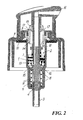
- Figure 2 is similar to Figure 1, but with the pump operating stem pressed to the end of its dispensing stroke.
-
- The pump shown in the drawings comprises a cup-
shaped body 1 defining achamber 2 presenting at its lower end a hole from which there extends ahollow appendix 3 on which one end of a dip tube, not shown in the drawings for simplicity, can be sealedly mounted in known manner: at said hole there is provided a unidirectional valve comprising aball 4 which can rest on and be sealedly urged (as shown in the drawings) against a seat provided at said hole, or can be raised away from said seat, to prevent outflow of fluid from thechamber 2 or to enable fluid to enter said chamber through theappendix 3 respectively. - The pump also comprises a
hollow stem 5, of which the upper portion (with respect to the drawings) projects from the cup-shaped body and the lower portion (with which apeg 6 forms an integral part) extends into thechamber 2. - A
piston 7 is mounted sealedly slidable on thestem 5 and is also sealedly slidable on the opposing inner surface of thebody 1, in correspondence with thechamber 2. - A
sleeve 8 is rigid with the upper end (again with respect to the drawings) of thebody 1 and is sealedly locked onto the free edge of thebody 1 by a profiledring cap 9 which can be fixed (by way of an elastic seal ring 10) onto the mouth of a container (not shown for simplicity) on which the pump is to be mounted. - The interior of the
chamber 2 houses aspring 11 which is compressed and acts between the base of the cup-shaped body and acollar 12 projecting from the hollow stem (specifically from thepeg 6 which forms an integral part of the stem) in order to urge it upwards: when the pump is in the rest state (Figure 1) thecollar 12 is urged against atubular lip 13 of the piston 7 (to seal against it), the piston in its turn being urged to seal against atubular lip 14 projecting from thesleeve 8. - It can be seen from Figure 1 that, when in the aforedescribed rest state, the
piston 7 sealedly closes (with its lip 13) ahole 15 provided between thestem 5 and thepeg 6 and communicating with the cavity of the stem, on the free end of which a dispensing pushbutton orcap 16 of known type is mounted. - Again examining the upper part of the figures of the drawings, there can be seen projecting from the sleeve 8 a
tubular lip 17 on which there sealedly presses (when the pump is in its rest state of Figure 1) anannular collar 18 which projects from thestem 5 outside thechamber 2 and above thepiston 7. - Finally it can be seen that the
ring 10 is shaped such as not to seal against the outer surface of the body 1 (for example thering 10 has a central hole with a profile different from that of the adjacent outer surface of the body 1), there projecting from thesleeve 8 anappendix 19 having an opening through which thestem 5 extends and is axially slidable, thisappendix 19 also not sealing against the outer surface of the stem: the non-existence of a seal between thering 10 and thebody 1 and between theappendix 19 and thestem 5 is a known fact, necessary to enable external air to penetrate into the container on which the pump is mounted, when the pump is operated (for example when at the end of the dispensing stroke of Figure 2) to draw into thechamber 2 the substance contained in the container and which the pump is intended to dispense. - The problem exists of preventing the fluid substance (which in the case of the described pump is of creamy type) from flowing or passing to the outside of the pump at the outer surface of the pump stem when the pump is at rest (Figure 1) and lies with the pump facing downwards with respect to the container on which it is mounted, notwithstanding the existence of the said air passageways. In other words, the pump must be such as to enable air to enter the container when the pump is operated, but the pump must ensure a perfect seal against accidental leakages of creamy substance when the pump is at rest.
- The presence of the two
tubular lips sleeve 8 and are simultaneously maintained pressed (by the spring 11) against theannular collars
Claims (2)
- A manually operable pump comprisingcharacterised in that said sleeve (8) presents a first tubular lip (14) against which said piston (7) rests and seals when the pump is in its rest position, and a second tubular lip (17) against which a first annular collar (18) projecting from the stem (5) outside the pump chamber (2) rests and seals when the pump is in its rest position.a cup-shaped body (1) defining an intake and compression chamber (2) for a creamy substance, which can enter the chamber (2) at one end through a hole provided in the cup-shaped body (1) and intercepted by a unidirectional valve (4),a hollow stem (5), of which a portion projects from the cup-shaped body (1) and another portion extends into said chamber (2),a piston (7) mounted on the stem (5) and sealing both against the stem and against the opposing surface of said chamber (2), said piston (7) bounding said chamber at its other end and being movable between a position in which it sealedly closes a hole (15) provided in the stem (5) and communicating with the stem cavity, and a position in which it leaves said hole (15) free to enable the creamy substance to flow from said chamber (2) to the outside of the pump through the stem cavity,a spring (11) acting between the cup-shaped body (1) and the stem (5) to urge this latter towards a sleeve (8) which is rigid with the cup-shaped body (1) on the outside of the pump chamber (2) and has an opening through which said stem (5) extends and is axially slidable,
- A pump as claimed in claim 1, characterised in that inside the pump chamber (2) there projects from said stem (5) a second annular collar (12) on which said piston (7) rests when the pump is in its rest position, to close and seal said stem hole (15) which communicates with the stem cavity.
Applications Claiming Priority (2)
| Application Number | Priority Date | Filing Date | Title |
|---|---|---|---|
| ITMI20041249 | 2004-06-22 | ||
| IT001249A ITMI20041249A1 (en) | 2004-06-22 | 2004-06-22 | MANUALLY OPERATED PUMP FOR DISPENSING CREAMY SUBSTANCES |
Publications (2)
| Publication Number | Publication Date |
|---|---|
| EP1609529A1 true EP1609529A1 (en) | 2005-12-28 |
| EP1609529B1 EP1609529B1 (en) | 2006-11-22 |
Family
ID=34956084
Family Applications (1)
| Application Number | Title | Priority Date | Filing Date |
|---|---|---|---|
| EP04030119A Active EP1609529B1 (en) | 2004-06-22 | 2004-12-20 | Manually operable pump for dispensing creamy substances |
Country Status (5)
| Country | Link |
|---|---|
| US (1) | US7108160B2 (en) |
| EP (1) | EP1609529B1 (en) |
| AT (1) | ATE345874T1 (en) |
| DE (1) | DE602004003356T2 (en) |
| IT (1) | ITMI20041249A1 (en) |
Cited By (2)
| Publication number | Priority date | Publication date | Assignee | Title |
|---|---|---|---|---|
| FR2913731A1 (en) * | 2007-03-12 | 2008-09-19 | Valois Sas | FLUID PRODUCT DELIVERY PUMP AND DISPENSER HAVING SUCH A PUMP |
| WO2008146319A3 (en) * | 2007-05-25 | 2009-03-12 | Emsar Spa | A dosing device for fluid products |
Families Citing this family (14)
| Publication number | Priority date | Publication date | Assignee | Title |
|---|---|---|---|---|
| US20070045349A1 (en) * | 2005-08-25 | 2007-03-01 | Continental Afa Dispensing Company | Liquid dispensing pump with shifting liquid piston |
| US20070110602A1 (en) * | 2005-11-17 | 2007-05-17 | Ever Rich Fountain Enterprise Co., Ltd | Pump |
| US20070119869A1 (en) * | 2005-11-25 | 2007-05-31 | Cheng-Yuan Su | Spray head |
| US7740154B2 (en) * | 2007-01-12 | 2010-06-22 | The Clorox Company | Bottle Fitment |
| FR2911640B1 (en) * | 2007-01-23 | 2012-09-21 | Rexam Dispensing Sys | PUMP FOR DISPENSING A DOSE OF FLUID PRODUCT AND RANGE COMPRISING SUCH PUMPS. |
| US7748576B2 (en) * | 2007-07-24 | 2010-07-06 | Hsih Tung Tooling Co., Ltd. | Pump assembly with pressable head |
| IT1393854B1 (en) * | 2009-04-01 | 2012-05-11 | Emsar Spa | DISPENSER. |
| IT1395730B1 (en) * | 2009-07-31 | 2012-10-19 | Lumson Spa | "CONTAINER ASSOCIATED WITH PUMPS AIRLESS AND METHOD FOR ITS REALIZATION" |
| CN201579158U (en) * | 2009-12-21 | 2010-09-15 | 陈秋火 | Back suction type drip-proof shower nozzle |
| US20110240677A1 (en) * | 2010-03-03 | 2011-10-06 | Walter Dwyer | Airless double-piston double-action pump and cosmetics bottle dispensing device |
| US20110303702A1 (en) * | 2010-06-11 | 2011-12-15 | Derxin (Shanghai) Cosmetics Co., Ltd. | Liquid spray head assembly |
| ITVI20130130A1 (en) * | 2013-05-08 | 2014-11-09 | Taplast Srl | DEVICE FOR DISTRIBUTION OF FLUIDS. |
| USD717666S1 (en) | 2014-03-14 | 2014-11-18 | The Clorox Company | Fluid dispenser |
| JP6882637B2 (en) * | 2015-12-24 | 2021-06-02 | イル カン,スン | Contents discharge pump |
Citations (2)
| Publication number | Priority date | Publication date | Assignee | Title |
|---|---|---|---|---|
| US3583605A (en) * | 1969-01-17 | 1971-06-08 | Diamond Int Corp | Liquid dispensing pump |
| DE1728199A1 (en) | 1968-09-09 | 1972-02-17 | Zeller Plastik Koehn Graebner | Closure with conveying and dispensing device for liquids |
Family Cites Families (9)
| Publication number | Priority date | Publication date | Assignee | Title |
|---|---|---|---|---|
| FR2686377B1 (en) * | 1992-01-20 | 1994-03-25 | Valois | IMPROVED PRECOMPRESSION PUMP. |
| FR2764005B1 (en) * | 1997-05-29 | 2004-12-10 | Sofab | ARTICULATED PISTON PUMP |
| US6209759B1 (en) * | 1997-07-04 | 2001-04-03 | Valois S.A. | Hand-operated pump with a free floating sleeve piston |
| FR2791400B1 (en) * | 1999-03-22 | 2002-04-26 | Sofab | RESPIRATION PUMP |
| FR2795779B1 (en) * | 1999-06-30 | 2001-09-14 | Valois Sa | IMPROVED PRE-PRESSURE PUMP |
| US6145710A (en) * | 1999-08-09 | 2000-11-14 | Carter; Miro S. | Metered output fluid dispenser |
| FR2810645B1 (en) * | 2000-06-22 | 2002-10-25 | Valois Sa | FLUID PRODUCT DISPENSING DEVICE |
| US6554160B2 (en) * | 2001-03-22 | 2003-04-29 | Valois S.A. | Dispenser member such as a pump or a valve |
| US20040069811A1 (en) * | 2002-10-10 | 2004-04-15 | Valois S.A.S. | Fixing member for fixing a dispensing member to an opening of a reservoir, and a dispenser including such a fixing member |
-
2004
- 2004-06-22 IT IT001249A patent/ITMI20041249A1/en unknown
- 2004-12-01 US US11/000,082 patent/US7108160B2/en active Active
- 2004-12-20 EP EP04030119A patent/EP1609529B1/en active Active
- 2004-12-20 DE DE602004003356T patent/DE602004003356T2/en active Active
- 2004-12-20 AT AT04030119T patent/ATE345874T1/en not_active IP Right Cessation
Patent Citations (2)
| Publication number | Priority date | Publication date | Assignee | Title |
|---|---|---|---|---|
| DE1728199A1 (en) | 1968-09-09 | 1972-02-17 | Zeller Plastik Koehn Graebner | Closure with conveying and dispensing device for liquids |
| US3583605A (en) * | 1969-01-17 | 1971-06-08 | Diamond Int Corp | Liquid dispensing pump |
Cited By (4)
| Publication number | Priority date | Publication date | Assignee | Title |
|---|---|---|---|---|
| FR2913731A1 (en) * | 2007-03-12 | 2008-09-19 | Valois Sas | FLUID PRODUCT DELIVERY PUMP AND DISPENSER HAVING SUCH A PUMP |
| WO2008129187A1 (en) * | 2007-03-12 | 2008-10-30 | Valois Sas | Pump for dispensing liquid product and dispenser comprising such pump |
| US8292130B2 (en) | 2007-03-12 | 2012-10-23 | Aptar France Sas | Pump for distributing liquid product and dispenser comprising such a pump |
| WO2008146319A3 (en) * | 2007-05-25 | 2009-03-12 | Emsar Spa | A dosing device for fluid products |
Also Published As
| Publication number | Publication date |
|---|---|
| ITMI20041249A1 (en) | 2004-09-22 |
| DE602004003356D1 (en) | 2007-01-04 |
| EP1609529B1 (en) | 2006-11-22 |
| US20050279770A1 (en) | 2005-12-22 |
| DE602004003356T2 (en) | 2007-09-13 |
| US7108160B2 (en) | 2006-09-19 |
| ATE345874T1 (en) | 2006-12-15 |
Similar Documents
| Publication | Publication Date | Title |
|---|---|---|
| US7108160B2 (en) | Manually operable pump for dispensing creamy substances | |
| US5738250A (en) | Liquid dispensing pump having water seal | |
| KR100346034B1 (en) | Manually operated spray device for liquid | |
| US7802701B2 (en) | Up-lock seal for dispenser pump | |
| EP1872859B1 (en) | Simplified pump for dispensing fluid substances withdrawn from a container | |
| US6974055B2 (en) | Adapter for a manually operated dispensing device of containers of liquid | |
| US4389003A (en) | Sliding inlet seal for an atomizing pump dispenser | |
| EP0222609B1 (en) | Dispenser pump | |
| US6824021B2 (en) | Actuating head of a double-acting pump for ejecting a product from a container | |
| US20030183655A1 (en) | Fluid dispensing device | |
| EP0179853A1 (en) | Pump for dispensing liquid from a container. | |
| KR850000600A (en) | Hand pump with flexible Pisonton | |
| JP2005503263A (en) | Dosing device with medium reservoir and pump device therefor | |
| JP2000189859A (en) | Manual pump | |
| US5738252A (en) | Upright/inverted sprayer | |
| US3949910A (en) | Dispensing pump | |
| JP2000504618A (en) | Manual fluid distribution pump | |
| US9296003B2 (en) | Dispensing pump | |
| US9884335B2 (en) | Hand held dispenser | |
| EP1525923A1 (en) | Manually operable invertible pump for dispensing atomized liquids | |
| JP2019507067A (en) | Discharge member and dispenser provided with the member | |
| JP3836312B2 (en) | Liquid jet pump | |
| US5110271A (en) | Hand-operable double-action metering and/or atomizing pump | |
| GB2051969A (en) | A Liquid Metering Device | |
| US7073690B2 (en) | Invertible pump with air passageways, for dispensing atomized liquids |
Legal Events
| Date | Code | Title | Description |
|---|---|---|---|
| PUAI | Public reference made under article 153(3) epc to a published international application that has entered the european phase |
Free format text: ORIGINAL CODE: 0009012 |
|
| AK | Designated contracting states |
Kind code of ref document: A1 Designated state(s): AT BE BG CH CY CZ DE DK EE ES FI FR GB GR HU IE IS IT LI LT LU MC NL PL PT RO SE SI SK TR |
|
| AX | Request for extension of the european patent |
Extension state: AL BA HR LV MK YU |
|
| 17P | Request for examination filed |
Effective date: 20051121 |
|
| GRAP | Despatch of communication of intention to grant a patent |
Free format text: ORIGINAL CODE: EPIDOSNIGR1 |
|
| RAP1 | Party data changed (applicant data changed or rights of an application transferred) |
Owner name: LUMSON S.P.A. |
|
| AKX | Designation fees paid |
Designated state(s): AT BE BG CH CY CZ DE DK EE ES FI FR GB GR HU IE IS IT LI LT LU MC NL PL PT RO SE SI SK TR |
|
| GRAS | Grant fee paid |
Free format text: ORIGINAL CODE: EPIDOSNIGR3 |
|
| GRAA | (expected) grant |
Free format text: ORIGINAL CODE: 0009210 |
|
| AK | Designated contracting states |
Kind code of ref document: B1 Designated state(s): AT BE BG CH CY CZ DE DK EE ES FI FR GB GR HU IE IS IT LI LT LU MC NL PL PT RO SE SI SK TR |
|
| PG25 | Lapsed in a contracting state [announced via postgrant information from national office to epo] |
Ref country code: LI Free format text: LAPSE BECAUSE OF FAILURE TO SUBMIT A TRANSLATION OF THE DESCRIPTION OR TO PAY THE FEE WITHIN THE PRESCRIBED TIME-LIMIT Effective date: 20061122 Ref country code: AT Free format text: LAPSE BECAUSE OF FAILURE TO SUBMIT A TRANSLATION OF THE DESCRIPTION OR TO PAY THE FEE WITHIN THE PRESCRIBED TIME-LIMIT Effective date: 20061122 Ref country code: SI Free format text: LAPSE BECAUSE OF FAILURE TO SUBMIT A TRANSLATION OF THE DESCRIPTION OR TO PAY THE FEE WITHIN THE PRESCRIBED TIME-LIMIT Effective date: 20061122 Ref country code: BE Free format text: LAPSE BECAUSE OF FAILURE TO SUBMIT A TRANSLATION OF THE DESCRIPTION OR TO PAY THE FEE WITHIN THE PRESCRIBED TIME-LIMIT Effective date: 20061122 Ref country code: CZ Free format text: LAPSE BECAUSE OF FAILURE TO SUBMIT A TRANSLATION OF THE DESCRIPTION OR TO PAY THE FEE WITHIN THE PRESCRIBED TIME-LIMIT Effective date: 20061122 Ref country code: RO Free format text: LAPSE BECAUSE OF FAILURE TO SUBMIT A TRANSLATION OF THE DESCRIPTION OR TO PAY THE FEE WITHIN THE PRESCRIBED TIME-LIMIT Effective date: 20061122 Ref country code: CH Free format text: LAPSE BECAUSE OF FAILURE TO SUBMIT A TRANSLATION OF THE DESCRIPTION OR TO PAY THE FEE WITHIN THE PRESCRIBED TIME-LIMIT Effective date: 20061122 Ref country code: LT Free format text: LAPSE BECAUSE OF FAILURE TO SUBMIT A TRANSLATION OF THE DESCRIPTION OR TO PAY THE FEE WITHIN THE PRESCRIBED TIME-LIMIT Effective date: 20061122 Ref country code: FI Free format text: LAPSE BECAUSE OF FAILURE TO SUBMIT A TRANSLATION OF THE DESCRIPTION OR TO PAY THE FEE WITHIN THE PRESCRIBED TIME-LIMIT Effective date: 20061122 Ref country code: PL Free format text: LAPSE BECAUSE OF FAILURE TO SUBMIT A TRANSLATION OF THE DESCRIPTION OR TO PAY THE FEE WITHIN THE PRESCRIBED TIME-LIMIT Effective date: 20061122 Ref country code: NL Free format text: LAPSE BECAUSE OF FAILURE TO SUBMIT A TRANSLATION OF THE DESCRIPTION OR TO PAY THE FEE WITHIN THE PRESCRIBED TIME-LIMIT Effective date: 20061122 Ref country code: SK Free format text: LAPSE BECAUSE OF FAILURE TO SUBMIT A TRANSLATION OF THE DESCRIPTION OR TO PAY THE FEE WITHIN THE PRESCRIBED TIME-LIMIT Effective date: 20061122 |
|
| REG | Reference to a national code |
Ref country code: GB Ref legal event code: FG4D |
|
| REG | Reference to a national code |
Ref country code: CH Ref legal event code: EP |
|
| PG25 | Lapsed in a contracting state [announced via postgrant information from national office to epo] |
Ref country code: IE Free format text: LAPSE BECAUSE OF NON-PAYMENT OF DUE FEES Effective date: 20061220 |
|
| REG | Reference to a national code |
Ref country code: IE Ref legal event code: FG4D |
|
| PG25 | Lapsed in a contracting state [announced via postgrant information from national office to epo] |
Ref country code: MC Free format text: LAPSE BECAUSE OF NON-PAYMENT OF DUE FEES Effective date: 20061231 |
|
| REF | Corresponds to: |
Ref document number: 602004003356 Country of ref document: DE Date of ref document: 20070104 Kind code of ref document: P |
|
| PG25 | Lapsed in a contracting state [announced via postgrant information from national office to epo] |
Ref country code: BG Free format text: LAPSE BECAUSE OF FAILURE TO SUBMIT A TRANSLATION OF THE DESCRIPTION OR TO PAY THE FEE WITHIN THE PRESCRIBED TIME-LIMIT Effective date: 20070222 Ref country code: DK Free format text: LAPSE BECAUSE OF FAILURE TO SUBMIT A TRANSLATION OF THE DESCRIPTION OR TO PAY THE FEE WITHIN THE PRESCRIBED TIME-LIMIT Effective date: 20070222 Ref country code: SE Free format text: LAPSE BECAUSE OF FAILURE TO SUBMIT A TRANSLATION OF THE DESCRIPTION OR TO PAY THE FEE WITHIN THE PRESCRIBED TIME-LIMIT Effective date: 20070222 |
|
| PG25 | Lapsed in a contracting state [announced via postgrant information from national office to epo] |
Ref country code: ES Free format text: LAPSE BECAUSE OF FAILURE TO SUBMIT A TRANSLATION OF THE DESCRIPTION OR TO PAY THE FEE WITHIN THE PRESCRIBED TIME-LIMIT Effective date: 20070305 |
|
| PG25 | Lapsed in a contracting state [announced via postgrant information from national office to epo] |
Ref country code: IS Free format text: LAPSE BECAUSE OF FAILURE TO SUBMIT A TRANSLATION OF THE DESCRIPTION OR TO PAY THE FEE WITHIN THE PRESCRIBED TIME-LIMIT Effective date: 20070322 |
|
| PG25 | Lapsed in a contracting state [announced via postgrant information from national office to epo] |
Ref country code: PT Free format text: LAPSE BECAUSE OF FAILURE TO SUBMIT A TRANSLATION OF THE DESCRIPTION OR TO PAY THE FEE WITHIN THE PRESCRIBED TIME-LIMIT Effective date: 20070423 |
|
| NLV1 | Nl: lapsed or annulled due to failure to fulfill the requirements of art. 29p and 29m of the patents act | ||
| ET | Fr: translation filed | ||
| REG | Reference to a national code |
Ref country code: CH Ref legal event code: PL |
|
| PLBE | No opposition filed within time limit |
Free format text: ORIGINAL CODE: 0009261 |
|
| STAA | Information on the status of an ep patent application or granted ep patent |
Free format text: STATUS: NO OPPOSITION FILED WITHIN TIME LIMIT |
|
| 26N | No opposition filed |
Effective date: 20070823 |
|
| PG25 | Lapsed in a contracting state [announced via postgrant information from national office to epo] |
Ref country code: GR Free format text: LAPSE BECAUSE OF FAILURE TO SUBMIT A TRANSLATION OF THE DESCRIPTION OR TO PAY THE FEE WITHIN THE PRESCRIBED TIME-LIMIT Effective date: 20070223 |
|
| PG25 | Lapsed in a contracting state [announced via postgrant information from national office to epo] |
Ref country code: EE Free format text: LAPSE BECAUSE OF FAILURE TO SUBMIT A TRANSLATION OF THE DESCRIPTION OR TO PAY THE FEE WITHIN THE PRESCRIBED TIME-LIMIT Effective date: 20061122 |
|
| PG25 | Lapsed in a contracting state [announced via postgrant information from national office to epo] |
Ref country code: TR Free format text: LAPSE BECAUSE OF FAILURE TO SUBMIT A TRANSLATION OF THE DESCRIPTION OR TO PAY THE FEE WITHIN THE PRESCRIBED TIME-LIMIT Effective date: 20061122 Ref country code: LU Free format text: LAPSE BECAUSE OF NON-PAYMENT OF DUE FEES Effective date: 20061220 Ref country code: HU Free format text: LAPSE BECAUSE OF FAILURE TO SUBMIT A TRANSLATION OF THE DESCRIPTION OR TO PAY THE FEE WITHIN THE PRESCRIBED TIME-LIMIT Effective date: 20070523 |
|
| PG25 | Lapsed in a contracting state [announced via postgrant information from national office to epo] |
Ref country code: CY Free format text: LAPSE BECAUSE OF FAILURE TO SUBMIT A TRANSLATION OF THE DESCRIPTION OR TO PAY THE FEE WITHIN THE PRESCRIBED TIME-LIMIT Effective date: 20061122 |
|
| REG | Reference to a national code |
Ref country code: FR Ref legal event code: PLFP Year of fee payment: 12 |
|
| REG | Reference to a national code |
Ref country code: FR Ref legal event code: PLFP Year of fee payment: 13 |
|
| REG | Reference to a national code |
Ref country code: FR Ref legal event code: PLFP Year of fee payment: 14 |
|
| PGFP | Annual fee paid to national office [announced via postgrant information from national office to epo] |
Ref country code: GB Payment date: 20231227 Year of fee payment: 20 |
|
| PGFP | Annual fee paid to national office [announced via postgrant information from national office to epo] |
Ref country code: IT Payment date: 20231122 Year of fee payment: 20 Ref country code: FR Payment date: 20231227 Year of fee payment: 20 Ref country code: DE Payment date: 20231117 Year of fee payment: 20 |