EP1609404A1 - Capsule type endoscope - Google Patents
Capsule type endoscope Download PDFInfo
- Publication number
- EP1609404A1 EP1609404A1 EP04723351A EP04723351A EP1609404A1 EP 1609404 A1 EP1609404 A1 EP 1609404A1 EP 04723351 A EP04723351 A EP 04723351A EP 04723351 A EP04723351 A EP 04723351A EP 1609404 A1 EP1609404 A1 EP 1609404A1
- Authority
- EP
- European Patent Office
- Prior art keywords
- capsule endoscope
- internal electric
- unit
- temperature
- power supply
- Prior art date
- Legal status (The legal status is an assumption and is not a legal conclusion. Google has not performed a legal analysis and makes no representation as to the accuracy of the status listed.)
- Withdrawn
Links
Images

Classifications
-
- A—HUMAN NECESSITIES
- A61—MEDICAL OR VETERINARY SCIENCE; HYGIENE
- A61B—DIAGNOSIS; SURGERY; IDENTIFICATION
- A61B1/00—Instruments for performing medical examinations of the interior of cavities or tubes of the body by visual or photographical inspection, e.g. endoscopes; Illuminating arrangements therefor
- A61B1/04—Instruments for performing medical examinations of the interior of cavities or tubes of the body by visual or photographical inspection, e.g. endoscopes; Illuminating arrangements therefor combined with photographic or television appliances
- A61B1/041—Capsule endoscopes for imaging
-
- A—HUMAN NECESSITIES
- A61—MEDICAL OR VETERINARY SCIENCE; HYGIENE
- A61B—DIAGNOSIS; SURGERY; IDENTIFICATION
- A61B1/00—Instruments for performing medical examinations of the interior of cavities or tubes of the body by visual or photographical inspection, e.g. endoscopes; Illuminating arrangements therefor
- A61B1/04—Instruments for performing medical examinations of the interior of cavities or tubes of the body by visual or photographical inspection, e.g. endoscopes; Illuminating arrangements therefor combined with photographic or television appliances
Definitions
- the present invention relates to a capsule endoscope shaped like a tablet, the capsule endoscope including a photographing optical system and an image pickup element.
- endoscope systems In examinations of, for example, a body cavity, endoscope systems have been generally in practical use and have been widespread. Various devices such as an endoscope, a light source, an image processor, and a display device are assembled into the endoscope system.
- the endoscope includes, for example, a tubular insertion portion having an image pickup element at the distal end thereof and an operation portion connected to the insertion portion.
- a universal cord extending from the insertion portion is connected to the light source and the image processor.
- the insertion portion is inserted into, for example, the mouth of a subject and is advanced through the body cavity thereof to observe a desired region.
- the light source has a lamp.
- the illumination light of the lamp is supplied to the endoscope.
- the image processor has a drive circuit for driving the image pickup element and an image processing circuit for producing video signals from electric signals photoelectrically converted through the image pickup element.
- the display receives the video signals produced by the image processing circuit in the image processor and displays an endoscopic image on a screen.
- the length of the insertion portion to be inserted into the body cavity is limited.
- the range of observation and examination is also limited.
- Japanese Unexamined Patent Application Publication No. 2001-95755 discloses a capsule endoscope system and includes various proposals.
- the capsule endoscope system primarily includes a small endoscope, namely, a capsule endoscope and a receiving and recording device.
- the capsule endoscope has image pickup means including a photographing optical system, illumination means, communication means, and power supply means and the like.
- the respective components are contained in a capsule-shaped casing.
- the receiving and recording device has communication means for communicating with the capsule endoscope by radio, and recording means for recording a received signal.
- the capsule endoscope for example, a subject swallows the capsule endoscope to introduce the capsule endoscope into their body cavity, so that the body cavity can be observed and examined.
- the capsule endoscope relatively easily achieves the observation and examination of a deep organ such as the small intestine. Generally, it is hard to observe and examine the small intestine using a conventional endoscope having the insertion portion.
- a power switch arranged in a predetermined position in the capsule endoscope is turned on and is then swallowed by a subject, thus starting endoscopy.
- the swallowed capsule endoscope advances through the body cavity of the subject by peristaltic motion of the gut and reaches a predetermined region to be observed and examined. Finally, the capsule endoscope is evacuated naturally.
- the power of the power supply is excessively supplied to an internal electric circuit, for example, if liquid and the like enter in a casing of the capsule endoscope or any trouble occurs in the internal electric circuit after the power switch of the capsule endoscope has been turned on, and the capsule endoscope has been introduced into the body cavity.
- the power of the power supply is consumed before the capsule endoscope reaches the desired position for observation, for example, as the result of a heavily increased consumption of the power.
- such problem occurs that observation or inspection cannot be made as desired.
- the present invention is to provide a capsule endoscope securing a higher safety by controlling for automatically interrupting the supply of power from the power supply in case any inconvenience or abnormality or the like has occurred in the internal electric circuit of the capsule endoscope introduced into the body cavity.
- the present invention is to provide a capsule endoscope which can avoid from obtaining in vain any image deteriorated in quality due to any inconvenience or the like occurred in the internal electric circuit system of the capsule endoscope inserted in the body cavity, thereby to make inspection or diagnosis or the like reliably at any time.
- the present invention provides a capsule endoscope including: temperature detecting means which is arranged in at least one of internal electric circuits and which detects an internal temperature of the corresponding internal electric circuit, converts information indicating the detected temperature into an electric signal in a predetermined form, and outputs the electric signal, the internal electric circuits constituting an image pickup unit, a signal processing unit, a communication unit, and an illumination unit, respectively; temperature determining means for performing a predetermined determination on the basis of the electric signal outputted from the temperature detecting means; and power control means for controlling power supply to the corresponding internal electric circuit on the basis of the determination result obtained by the temperature determining means.
- the temperature determining means determines that a trouble or an abnormal condition occurs in the corresponding internal electric circuit, so that the power control means performs a power-supply interruption control for interrupting the operation of the corresponding internal electric circuit.
- the capsule endoscope in the ON state which is put in a body cavity, can be changed to unavailable mode.
- a capsule endoscope system 10 has a capsule endoscope 1 and a receiving and recording device 2.
- the receiving and recording device 2 has a recording unit (not shown) for receiving image signals transmitted from the capsule endoscope 1 and recording the signals.
- the capsule endoscope 1 includes an image pickup unit 11, a signal processing unit 12, a communication unit 13, a power supply unit 14, an illumination unit 15, and a photographing optical system 16.
- the image pickup unit 11 functions as image pickup means and includes an image pickup element for receiving an image of an object, the image being formed by the photographing optical system 16, and performing predetermined photoelectric conversion to the image to generate predetermined image signals.
- the signal processing unit 12 serves as signal processing means for receiving the image signals outputted from the image pickup unit 11, performing various signal processing steps including a predetermined signal processing step to the received signals, and outputting the resultant image signals to the communication unit 13.
- the signal processing unit 12 also controls the illumination unit 15 and the image pickup unit 11. In other words, the signal processing unit 12 functions as a control unit for systematically controlling electric circuits included in the respective units of the capsule endoscope 1.
- the communication unit 13 functions as communication means for receiving the image signals generated from the signal processing unit 12 and for transmitting the signals to the receiving and recording device 2, arranged on the outside of the body of the subject, using predetermined radio communication means.
- the power supply unit 14 serves as power supply means for supplying power to the internal electric circuits, which are included in the image pickup unit 11, the signal processing unit 12, the communication unit 13, and the illumination unit 15, respectively.
- the power supply unit 14 supplies power to each unit by a predetermined amount required for the internal electric circuit included in the unit.
- the illumination unit 15 serves as illumination means for illuminating an object such as a digestive organ.
- the photographing optical system 16 forms the image of the object illuminated by the illumination unit 15.
- the image pickup unit 11 has the image pickup element for performing photoelectric conversion and the electric circuit including a plurality of electric components.
- the electric circuit performs the predetermined signal processing step to image signals serving as electric signals indicating the image.
- the electric signals are obtained by the photoelectric conversion through the image pickup element.
- the signal processing unit 12 has the electric circuit comprising a semiconductor circuit with a one-chip design. As mentioned above, the signal processing unit 12 performs various image signal processing steps and drive controls.
- the communication unit 13 includes the electric circuit for receiving signals generated from the signal processing unit 12 and for transmitting the signals to the receiving and recording device 2.
- the power supply unit 14 has the electric circuit comprising a plurality of electric components including a battery to supply a predetermined power to the respective electric circuits.
- the illumination unit 15 includes the electric circuit comprising a plurality of electric components such as light emitting diodes.
- the photographing optical system 16 includes, for example, a plurality of optical lenses and predetermined drive units for driving the optical lenses.
- the photographing optical system 16 converges a light beam, reflected from the object illuminated by the illumination unit 15, and forms the image of the object in a predetermined position, for example, on the image formation surface of the image pickup element in the image pickup unit 11.
- each internal electric circuit constituting each unit has a temperature detection circuit and predetermined means for controlling a circuit power supply included in the internal electric circuit.
- the internal electric circuit constituting the image pickup unit 11 has a temperature detection circuit 11a and an image pickup-unit power supply 11d, which will be described later.
- the internal electric circuit of the signal processing unit 12 has a temperature detection circuit 12a and predetermined means for controlling a power supply for the signal processing unit 12.
- the internal electric circuit of the communication unit 13 has a temperature detection circuit 13a and predetermined means for controlling a power supply for the communication unit 13.
- the internal electric circuit of the illumination unit 15 has a temperature detection circuit 15a and predetermined means for controlling a power supply for the illumination unit 15.
- Each predetermined means controlling the corresponding circuit power supply in the corresponding internal electric circuit, performs a predetermined determination on the basis of temperature information serving as a signal indicative of a temperature detected by the corresponding temperature detection circuit, 11a, 12a, 13a, 15a, and then performs a control action based on the determination result.
- Fig. 2 shows the image pickup unit 11 as an example.
- the image pickup unit 11 has the image pickup element and the electric circuit.
- the image pickup unit 11 further includes the image pickup-unit power supply 11d and an internal-circuit current controller 11c for controlling current flowing through the internal electric circuit constituting the image pickup unit 11.
- the image pickup-unit power supply 11d receives power from the power supply unit 14 in Fig. 1, and properly supplies the power to the electric circuit constituting the image pickup unit 11 by the required amount.
- the internal-circuit current controller 11c controls the image pickup-unit power supply 11d.
- Means for controlling the image pickup-unit power supply 11d includes the temperature detection circuit 11a, a comparator 11b serving as temperature determination means, and the internal-circuit current controller 11c serving as power control means.
- the temperature detection circuit 11a detects an internal or ambient temperature of the image pickup unit 11, converts information indicating the detected temperature into an electric signal in a predetermined form, and then generates the signal.
- the comparator 11b receives the signal from the temperature detection circuit 11a, compares the signal with a predetermined value as a reference temperature that is preset, and determines whether the detected temperature is higher than the predetermined value. The comparator 11b then outputs a predetermined signal indicating the determination result to the internal-circuit current controller 11c.
- the internal-circuit current controller 11c controls the operation of the image pickup-unit power supply 11d when the signal is equal to the predetermined value. For example, the internal-circuit current controller 11c allows the image pickup-unit power supply 11d to interrupt power supply.
- the temperature detection circuit 11a includes a resistor or a semiconductor circuit, which includes a diode, a bipolar transistor, or a metal-oxide-semiconductor transistor (MOS FET).
- the resistance of the resistor varies depending on, for example, temperature. Alternatively, the characteristics of the transistor vary depending on temperature.
- An output value of the temperature detection circuit 11a is generated as a temperature detection signal in a predetermined form.
- the temperature detection circuits 11a, 12a, 13a, and 15a each include a temperature detection device (not shown).
- the temperature detection devices are arranged in the internal electric circuits constituting the image pickup unit 11, the signal processing unit 12, the communication unit 13, and the illumination unit 15 in the capsule endoscope 1, respectively.
- the temperature detection device is included in at least one of the internal electric circuits.
- the temperature detection device includes a thermistor.
- the thermistor is integrated with each of the image pickup element (not shown) included in the image pickup unit 11, a processing circuit element (not shown) included in the signal processing unit 12, a communication element (not shown) included in the communication unit 13, and an illumination element (not shown) included in the illumination unit 15.
- the structure of each internal electric circuit is substantially the same as that of the above-mentioned image pickup unit 11.
- the internal electric circuit includes a circuit power supply for the corresponding unit, the temperature detection circuits 12a, 13a, and 15a, a comparator 11b, and an internal-circuit current controller 11c.
- the capsule endoscope 1 with the above configuration is used in combination with the receiving and recording device 2 having the recording unit for receiving image signals, captured and transmitted through the capsule endoscope 1, and for recording the signals.
- the image signals for observation of a desired region in the body cavity can be obtained and be recorded.
- the image signals obtained in this manner are output to, for example, a predetermined display to display an image corresponding to the image signals.
- the image is observed, so that examination and diagnosis can be made on the basis of the observation.
- the subject In examination using the capsule endoscope 1, the subject first swallows the capsule endoscope 1. Before the subject swallows the capsule endoscope 1, a predetermined power switch is turned on, thus activating the capsule endoscope 1. The swallowed capsule endoscope 1 advances through the body cavity of the subject by peristaltic motion and reaches an object region to be observed and examined.
- the body cavity is illuminated by the illumination unit 15 in the capsule endoscope 1 under operating conditions. Consequently, the image of the illuminated object is formed on the image formation surface of the image pickup unit 11 through the photographing optical system 16.
- the image pickup unit 11 performs predetermined photoelectric conversion to the optical image formed on the image formation surface. Thus, image signals corresponding to the image of the object are output to the signal processing unit 12.
- the signal processing unit 12 performs various signal processing steps to the supplied image signals.
- the resultant image signals are output to the communication unit 13.
- the communication unit 13 transmits the image signals to the receiving and recording device 2 provided in combination with the capsule endoscope 1.
- the receiving and recording device 2 converts the signals into signals in the optimum form for recording and then records the converted signals into a predetermined recording medium (not shown) included therein.
- the temperature detection circuits 11a, 12a, 13a, and 15a each start the execution of the temperature detecting operation.
- the circuits 11a, 12a, 13a, and 15a are integrated with the image pickup unit 11, the signal processing unit 12, the communication unit 13, and the illumination unit 15, respectively.
- the temperature detection circuits 11a, 12a, 13a, and 15a each detect a temperature to produce a detection signal, namely, a signal indicating temperature information of the corresponding unit.
- the detection signal is output from each temperature detection circuit to the corresponding comparator.
- the detection signal is generated from the temperature detection circuit 11a to the comparator 11b.
- Each comparator compares the signal, supplied from the corresponding temperature detection circuit, with the predetermined value.
- the comparator 11b compares the signal supplied from the temperature detection circuit 11a with the predetermined value.
- Each comparator generates the comparison result to the corresponding internal-circuit current controller.
- the comparator 11b outputs the comparison result to the internal-circuit current controller 11c.
- Each internal-circuit current controller 11c, and the like conducts a predetermined determination process on the basis of the comparison result supplied from the corresponding comparator 11b, and the like.
- each internal-circuit current controller When receiving the comparison result indicating that the output value of the corresponding temperature detection circuit 11a, 12a, 13a and 15a is higher than each reference temperature, each internal-circuit current controller performs a predetermined control process to stop the operation of the corresponding internal electric circuit.
- the internal-circuit current controller controls the corresponding power supply to interrupt power supply to the corresponding internal electric circuit among the image pickup unit 11, the signal processing unit 12, the communication unit 13 and the illumination unit 15.
- the control is called a power-supply interruption control (also referred to as an OFF control).
- the internal-circuit current controller 11c controls the image pickup-unit power supply 11d to interrupt power supply to the corresponding internal electric circuit.
- the internal-circuit current controller 11c, and the like determines that the corresponding internal electric circuit has a trouble or an abnormal condition, and then performs the control process to interrupt the operation of the corresponding internal electric circuit.
- the capsule endoscope 1 is unavailable.
- the capsule endoscope 1 advances through the body cavity by peristaltic motion of the gut as mentioned above. Finally, the capsule endoscope 1 is naturally evacuated from the body cavity with safety and reliability.
- a temperature of each internal electric circuit is detected.
- the power-supply interruption control for interrupting power supply to the internal electric circuit is automatically executed, so that the operation of the capsule endoscope 1 can be stopped.
- the capsule endoscope 1 in the OFF state is naturally evacuated from the body cavity.
- each internal electric circuit has the temperature detection circuit.
- temperatures of the respective internal electric circuits can be detected with higher accuracy.
- a predetermined reference temperature can be specified in each internal electric circuit. Consequently, control with more detailed settings can be easily performed.
- the temperature detection circuit 11a detects the increase in temperature of the image pickup unit 11, determines that the electric circuit included in the image pickup unit 11 has a trouble or an abnormal condition, and performs the power-supply interruption control to stop the operation of the image pickup unit 11.
- the temperature detection circuits 11a, 12a, 13a, and 15a are arranged as temperature detection means for detecting temperatures in the respective internal electric circuits.
- the temperature detection circuits 11a, 12a, 13a, and 15a for example, current detection circuits for detecting a current supplied to the corresponding internal electric circuit may be used.
- each internal electric circuit includes the current detection circuit, components of the internal electric circuit and the corresponding control process are modified in accordance with the modified configuration of the circuit.
- each comparator arranged subsequent to the current detection circuit, receives an output of the current detection circuit and compares a current signal with a reference current as a predetermined value in advance.
- the comparison result is supplied to the corresponding internal-circuit current controller.
- the internal-circuit current controller performs a determination process based on the comparison result supplied from the comparator.
- the internal-circuit current controller When receiving the comparison result indicating that an output of the current detection circuit is abnormal in comparison with the predetermined reference current, the internal-circuit current controller performs a predetermined control process to stop the operation of the corresponding internal electric circuit included with the illumination unit 15, the image pickup unit 11, the signal processing unit 12 or the communication unit 13.
- the control process is the same as that of the above-mentioned first embodiment, namely, the power-supply interruption control for controlling the circuit power supply.
- the current detection circuits for directly detecting a current flowing through the corresponding internal electric circuit instead of the temperature detection circuits according to the first embodiment, when the detection result of the current flowing through the internal electric circuit constituting, for example, the illumination unit indicates zero, it can be determined that the illumination operation is not performed. Because the illumination unit has a trouble, for example, an illumination light source member is unavailable in spite of the fact that power is supplied through the corresponding circuit power supply.
- the detection signals of the temperature detection circuits 11a, 12a, 13a, and 15a in the respective internal electric circuits are supplied to the corresponding comparators, respectively.
- Each comparator compares the received signal with the predetermined reference temperature.
- the comparison result is supplied to the corresponding internal-circuit current controller.
- the internal-circuit current controller performs the predetermined control process.
- the respective detection signals of the temperature detection circuits 11a, 12a, 13a, and 15a can be transmitted to the receiving and recording device 2 through the communication unit 13.
- the receiving and recording device 2 includes means corresponding to the comparator 11b and means corresponding to the internal-circuit current controller 11c. Accordingly, in the receiving and recording device 2, whether each internal electric circuit in the capsule endoscope 1 has a trouble or an abnormal condition is determined on the basis of the corresponding detection signal transmitted from the communication unit 13. A predetermined control signal based on the determination result may be transmitted to the corresponding internal electric circuit through the communication unit 13 in the capsule endoscope 1.
- the respective internal electric circuits in the capsule endoscope 1 can be easily simplified.
- the capsule endoscope 1 can be further miniaturized, resulting in the reduction in manufacturing cost.
- the power supply unit 14 is arranged in the capsule endoscope 1.
- the placement of the power supply unit 14 is not limited to the interior of the capsule endoscope 1.
- the power supply unit 14 can be placed in the exterior of the capsule endoscope 1, namely, a device which is not inserted into the body cavity and is used in the outside of the body. That is, the power supply unit 14 may be provided for the receiving and recording device 2 or an external power supply device, which is arranged separately from the receiving and recording device 2 and includes a predetermined power supply circuit. Power is supplied from the above-mentioned device through predetermined radio communication means. In other words, a so-called wireless power supply method can be used.
- the capsule endoscope 1 includes a receiving unit having means for receiving power supplied from the above-mentioned external power supply device in a wireless manner and for distributing the received power to the respective internal electric circuits in the capsule endoscope 1.
- a receiving unit having means for receiving power supplied from the above-mentioned external power supply device in a wireless manner and for distributing the received power to the respective internal electric circuits in the capsule endoscope 1.
- the signal processing unit 12 can communicate with the external power supply device through the communication unit 13 or the receiving unit so that the predetermined power-supply interruption control is performed in order to shut off power supply.
- the capsule endoscope 1 which receives power from the external power supply device in a wireless manner to drive the respective internal electric circuits, is controlled so that continuously-supplied power is shut off in predetermined cases.
- an abnormal information signal as a predetermined signal indicating the occurrence of a trouble or an abnormal condition in the internal electric circuit can be formed by the signal processing unit 12. The signal is transmitted from the signal processing unit 12 to the receiving and recording device 2 through the communication unit 13.
- predetermined announcement means such as a buzzer or a lighting or flashing device using a light emitting diode can be provided for the receiving and recording device 2.
- the operator or the subject can immediately notice the occurrence of a trouble in the capsule endoscope 1 put in the body cavity. For example, just after the announcement of the trouble, the subject again swallows another capsule endoscope 1, so that the examination can be smoothly continued without being interrupted.
- the capsule endoscope 1 which has already been put into the body cavity and may have a trouble or abnormal condition is subjected to the predetermined power-supply interruption control in the same way as the above embodiment. Therefore, the capsule endoscope 1 in the OFF state is naturally evacuated.
- the arrangement of the above-mentioned announcement means may produce the following advantages.
- the power-supply interruption control for interrupting the operation of the image pickup unit 11 is performed in the same way as the above embodiment. At that time, capturing image signals through the capsule endoscope 1 is suspended. In other words, if the image pickup unit 11 has any trouble or an abnormal condition, the use of the capsule endoscope 1 can be interrupted without uselessly capturing image signals with a large amount of noise components inappropriate for examination.
- the above-mentioned announcement means can immediately inform the operator or the subject of the occurrence of the trouble or abnormal condition in any internal electric circuit. Accordingly, at this time, the subject again swallows another capsule endoscope 1, so that the same examination can be continued. Therefore, time required for the examination is not wasted, resulting in more efficient examination and diagnosis.
- the temperature detection circuits 15a, 11a, 12a, and 13a are integrated with the illumination unit 15, the image pickup unit 11, the signal processing unit 12, and the communication unit 13, respectively.
- the present invention is not limited to the above structure.
- the present invention can be applied to any structure so long as a temperature in the interior of the capsule endoscope 1 can be detected by at least one temperature detection circuit 12a.
- any one of the internal electric circuits integrally can include a temperature detection circuit.
- the signal processing unit 12 integrally may include the temperature detection circuit 12a.
- the same advantages as those of the first embodiment can be obtained.
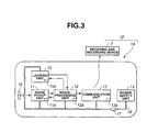
- Fig. 3 shows a capsule endoscope 1A according to a second embodiment of the present invention.
- the capsule endoscope 1A has substantially the same structure as that of the capsule endoscope 1 according to the first embodiment.
- the capsule endoscope 1A differs from the capsule endoscope 1 in such a way that the capsule endoscope 1A includes a thermal fuse 17 in a power/signal line 18 serving as a part of internal electric circuits.
- the capsule endoscope 1A has the thermal fuse 17 on the power/signal line 18 near the power supply unit 14.
- the respective internal electric circuits of the capsule endoscope 1A are connected to the power supply unit 14 through the thermal fuse 17.
- the other arrangement and components are the same as those of the first embodiment.
- the components similar to those of the first embodiment are referenced using the same reference numerals to omit the description thereof.
- the corresponding temperature detection circuit 11a, 12a, 13a, or 15a performs the power-supply interruption control.
- the power supply unit 14 supplies an excess of power and current exceeds the rated value of the thermal fuse 17, the thermal fuse 17 is disconnected. Consequently, the power supply through the power supply unit 14 is completely shut off, resulting in the interruption of the operation of the capsule endoscope 1A.
- the thermal fuse 17 is disconnected in the excess power supply mode of the power supply unit 14, so that the power supply from the power supply unit 14 to the internal electric circuits is interrupted.
- the power supply interruption control can be performed with more reliability.
- the thermal fuse 17 is arranged in the power/signal line 18.
- a thermistor serving as a resistor whose resistance varies depending on temperature can be arranged.
- the same advantages as those of the second embodiment can be obtained.
- the structure according to the second embodiment can be applied to the modifications of the first embodiment.
- the capsule endoscope 1A can be applied to the current detection circuits used instead of the temperature detection circuits, one temperature detection circuit provided for any one of the internal electric circuits, power supplied from the external power supply device in a wireless manner, and the other modifications.
- the same advantages as those of the first embodiment can be obtained.
- the capsule endoscope of the present invention controls to automatically interrupt the supply of power from the power supply when any inconvenience or abnormality or the like has occurred in the internal electric circuit system in the state that the capsule endoscope has been introduced into the body cavity. Therefore, the present invention is adapted to make reliable inspection or diagnosis or the like at any time while securing a higher safety by avoiding from obtaining in vain any image deteriorated in quality due to inconvenience or the like.
Landscapes
- Health & Medical Sciences (AREA)
- Life Sciences & Earth Sciences (AREA)
- Surgery (AREA)
- Biomedical Technology (AREA)
- Medical Informatics (AREA)
- Optics & Photonics (AREA)
- Pathology (AREA)
- Radiology & Medical Imaging (AREA)
- Biophysics (AREA)
- Engineering & Computer Science (AREA)
- Physics & Mathematics (AREA)
- Heart & Thoracic Surgery (AREA)
- Nuclear Medicine, Radiotherapy & Molecular Imaging (AREA)
- Molecular Biology (AREA)
- Animal Behavior & Ethology (AREA)
- General Health & Medical Sciences (AREA)
- Public Health (AREA)
- Veterinary Medicine (AREA)
- Endoscopes (AREA)
- Measurement Of The Respiration, Hearing Ability, Form, And Blood Characteristics Of Living Organisms (AREA)
Abstract
A capsule endoscope which can make reliable inspection
or diagnosis or the like at any time while securing a higher
safety by controlling such as to interrupt the supply of
power from a power supply when any inconvenience or
abnormality or the like has occurred in the internal
electric circuit system of the capsule endoscope in the
state that the capsule endoscope has been introduced into
the body cavity. In at least one of internal electric
circuits which form an image pickup unit 11, a signal
processing unit 12, a communication unit 13 and an
illumination unit 15 arranged in the capsule endoscope are
provided a temperature detection circuit 11a which detects
an internal temperature, converts information indicating the
detected temperature into an electric signal in a
predetermined form and then outputs the signal, a comparator
11b which receives the signal from the temperature detection
circuit 11a and make predetermined determination based on
the received signal, and an internal-circuit current
controller 11c which controls the supply of power to the
internal electric circuit based on the result of
determination by the comparator 11b.
Description
The present invention relates to a capsule endoscope
shaped like a tablet, the capsule endoscope including a
photographing optical system and an image pickup element.
In examinations of, for example, a body cavity,
endoscope systems have been generally in practical use and
have been widespread. Various devices such as an endoscope,
a light source, an image processor, and a display device are
assembled into the endoscope system.
The endoscope includes, for example, a tubular
insertion portion having an image pickup element at the
distal end thereof and an operation portion connected to the
insertion portion. A universal cord extending from the
insertion portion is connected to the light source and the
image processor. The insertion portion is inserted into,
for example, the mouth of a subject and is advanced through
the body cavity thereof to observe a desired region.
The light source has a lamp. The illumination light of
the lamp is supplied to the endoscope. The image processor
has a drive circuit for driving the image pickup element and
an image processing circuit for producing video signals from
electric signals photoelectrically converted through the
image pickup element. The display receives the video
signals produced by the image processing circuit in the
image processor and displays an endoscopic image on a screen.
In the conventional endoscope system, the length of the
insertion portion to be inserted into the body cavity is
limited. Thus, the range of observation and examination is
also limited.
For example, Japanese Unexamined Patent Application
Publication No. 2001-95755 discloses a capsule endoscope
system and includes various proposals. According to
Japanese Unexamined Patent Application Publication No. 2001-95755,
the capsule endoscope system primarily includes a
small endoscope, namely, a capsule endoscope and a receiving
and recording device. The capsule endoscope has image
pickup means including a photographing optical system,
illumination means, communication means, and power supply
means and the like. The respective components are contained
in a capsule-shaped casing. The receiving and recording
device has communication means for communicating with the
capsule endoscope by radio, and recording means for
recording a received signal.
According to the above-mentioned capsule endoscope
system, for example, a subject swallows the capsule
endoscope to introduce the capsule endoscope into their body
cavity, so that the body cavity can be observed and examined.
Advantageously, the capsule endoscope relatively easily
achieves the observation and examination of a deep organ
such as the small intestine. Generally, it is hard to
observe and examine the small intestine using a conventional
endoscope having the insertion portion.
In use of the capsule endoscope, a power switch
arranged in a predetermined position in the capsule
endoscope is turned on and is then swallowed by a subject,
thus starting endoscopy. The swallowed capsule endoscope
advances through the body cavity of the subject by
peristaltic motion of the gut and reaches a predetermined
region to be observed and examined. Finally, the capsule
endoscope is evacuated naturally.
In a structure of the capsule endoscope disclosed by
the Japanese Unexamined Patent Application Publication No.
2001-95755, however, its power switch cannot be returned to
OFF state if once turned on. It also fails to disclose
means to control the state of the power supply.
In other words, with the capsule endoscope disclosed by
the above Patent Application Publication, if a subject has
swallowed the capsule endoscope having the power switch
turned on, it is by no means possible to thereafter turn off
the power supply.
Hence, it might be possible that the power of the power
supply is excessively supplied to an internal electric
circuit, for example, if liquid and the like enter in a
casing of the capsule endoscope or any trouble occurs in the
internal electric circuit after the power switch of the
capsule endoscope has been turned on, and the capsule
endoscope has been introduced into the body cavity. On such
occasion, it comes about that the power of the power supply
is consumed before the capsule endoscope reaches the desired
position for observation, for example, as the result of a
heavily increased consumption of the power. As a
consequence, such problem occurs that observation or
inspection cannot be made as desired.
Meanwhile, it is well known that there is a tendency
with the image pickup means such as usual image pickup
element that the environment for use thereof is the one
under higher temperature, more noise components and the like
are caused in the image signal obtained. Therefore, in case
any video signal produced based on an image signal obtained
by an image pickup element under high temperature
environment has been displayed on a display device, there is
such problem that deterioration of the image quality can not
be avoided.
Incidentally, in case the power is excessively supplied
to the internal electric circuit of the capsule endoscope,
it comes about that internal temperature of the capsule
endoscope rises due to the cause as mentioned above, thereby
to deteriorate the environment for use of the image pickup
element. Then, further problem occurs that any endoscope
image excellent in image quality can not be obtained from
the image signal obtained at this time by the reasons as
mentioned above.
Therefore, the present invention is to provide a
capsule endoscope securing a higher safety by controlling
for automatically interrupting the supply of power from the
power supply in case any inconvenience or abnormality or the
like has occurred in the internal electric circuit of the
capsule endoscope introduced into the body cavity.
Also, the present invention is to provide a capsule
endoscope which can avoid from obtaining in vain any image
deteriorated in quality due to any inconvenience or the like
occurred in the internal electric circuit system of the
capsule endoscope inserted in the body cavity, thereby to
make inspection or diagnosis or the like reliably at any
time.
The present invention provides a capsule endoscope
including: temperature detecting means which is arranged in
at least one of internal electric circuits and which detects
an internal temperature of the corresponding internal
electric circuit, converts information indicating the
detected temperature into an electric signal in a
predetermined form, and outputs the electric signal, the
internal electric circuits constituting an image pickup unit,
a signal processing unit, a communication unit, and an
illumination unit, respectively; temperature determining
means for performing a predetermined determination on the
basis of the electric signal outputted from the temperature
detecting means; and power control means for controlling
power supply to the corresponding internal electric circuit
on the basis of the determination result obtained by the
temperature determining means. When the temperature
detecting means detects an increase in temperature, the
temperature determining means determines that a trouble or
an abnormal condition occurs in the corresponding internal
electric circuit, so that the power control means performs a
power-supply interruption control for interrupting the
operation of the corresponding internal electric circuit.
Thus, the capsule endoscope in the ON state, which is put in
a body cavity, can be changed to unavailable mode.
Hereinbelow, a description is given with reference to
the drawings.
Referring to Figs. 1 and 2, a first embodiment of the
present invention is described.
Referring to Fig. 1" a capsule endoscope system 10 has
a capsule endoscope 1 and a receiving and recording device 2.
The receiving and recording device 2 has a recording unit
(not shown) for receiving image signals transmitted from the
capsule endoscope 1 and recording the signals.
The capsule endoscope 1 includes an image pickup unit
11, a signal processing unit 12, a communication unit 13, a
power supply unit 14, an illumination unit 15, and a
photographing optical system 16.
The image pickup unit 11 functions as image pickup
means and includes an image pickup element for receiving an
image of an object, the image being formed by the
photographing optical system 16, and performing
predetermined photoelectric conversion to the image to
generate predetermined image signals. The signal processing
unit 12 serves as signal processing means for receiving the
image signals outputted from the image pickup unit 11,
performing various signal processing steps including a
predetermined signal processing step to the received signals,
and outputting the resultant image signals to the
communication unit 13. The signal processing unit 12 also
controls the illumination unit 15 and the image pickup unit
11. In other words, the signal processing unit 12 functions
as a control unit for systematically controlling electric
circuits included in the respective units of the capsule
endoscope 1. The communication unit 13 functions as
communication means for receiving the image signals
generated from the signal processing unit 12 and for
transmitting the signals to the receiving and recording
device 2, arranged on the outside of the body of the subject,
using predetermined radio communication means. The power
supply unit 14 serves as power supply means for supplying
power to the internal electric circuits, which are included
in the image pickup unit 11, the signal processing unit 12,
the communication unit 13, and the illumination unit 15,
respectively. The power supply unit 14 supplies power to
each unit by a predetermined amount required for the
internal electric circuit included in the unit. The
illumination unit 15 serves as illumination means for
illuminating an object such as a digestive organ. The
photographing optical system 16 forms the image of the
object illuminated by the illumination unit 15.
The image pickup unit 11 has the image pickup element
for performing photoelectric conversion and the electric
circuit including a plurality of electric components. The
electric circuit performs the predetermined signal
processing step to image signals serving as electric signals
indicating the image. The electric signals are obtained by
the photoelectric conversion through the image pickup
element.
The signal processing unit 12 has the electric circuit
comprising a semiconductor circuit with a one-chip design.
As mentioned above, the signal processing unit 12 performs
various image signal processing steps and drive controls.
The communication unit 13 includes the electric circuit
for receiving signals generated from the signal processing
unit 12 and for transmitting the signals to the receiving
and recording device 2.
The power supply unit 14 has the electric circuit
comprising a plurality of electric components including a
battery to supply a predetermined power to the respective
electric circuits.
The illumination unit 15 includes the electric circuit
comprising a plurality of electric components such as light
emitting diodes.
The photographing optical system 16 includes, for
example, a plurality of optical lenses and predetermined
drive units for driving the optical lenses. The
photographing optical system 16 converges a light beam,
reflected from the object illuminated by the illumination
unit 15, and forms the image of the object in a
predetermined position, for example, on the image formation
surface of the image pickup element in the image pickup unit
11.
In the capsule endoscope 1, each internal electric
circuit constituting each unit has a temperature detection
circuit and predetermined means for controlling a circuit
power supply included in the internal electric circuit. In
other words, referring to Figs. 1 and 2, the internal
electric circuit constituting the image pickup unit 11 has a
temperature detection circuit 11a and an image pickup-unit
power supply 11d, which will be described later. The
internal electric circuit of the signal processing unit 12
has a temperature detection circuit 12a and predetermined
means for controlling a power supply for the signal
processing unit 12. The internal electric circuit of the
communication unit 13 has a temperature detection circuit
13a and predetermined means for controlling a power supply
for the communication unit 13. The internal electric
circuit of the illumination unit 15 has a temperature
detection circuit 15a and predetermined means for
controlling a power supply for the illumination unit 15.
Each predetermined means, controlling the corresponding
circuit power supply in the corresponding internal electric
circuit, performs a predetermined determination on the basis
of temperature information serving as a signal indicative of
a temperature detected by the corresponding temperature
detection circuit, 11a, 12a, 13a, 15a, and then performs a
control action based on the determination result.
The schematic structure of the predetermined means for
controlling the corresponding circuit power supply in the
corresponding internal electric circuit will now be
described with reference to Fig. 2. Fig. 2 shows the image
pickup unit 11 as an example.
As mentioned above, the image pickup unit 11 has the
image pickup element and the electric circuit. The image
pickup unit 11 further includes the image pickup-unit power
supply 11d and an internal-circuit current controller 11c
for controlling current flowing through the internal
electric circuit constituting the image pickup unit 11.
The image pickup-unit power supply 11d receives power
from the power supply unit 14 in Fig. 1, and properly
supplies the power to the electric circuit constituting the
image pickup unit 11 by the required amount. The internal-circuit
current controller 11c controls the image pickup-unit
power supply 11d.
Means for controlling the image pickup-unit power
supply 11d includes the temperature detection circuit 11a, a
comparator 11b serving as temperature determination means,
and the internal-circuit current controller 11c serving as
power control means.
The temperature detection circuit 11a detects an
internal or ambient temperature of the image pickup unit 11,
converts information indicating the detected temperature
into an electric signal in a predetermined form, and then
generates the signal. The comparator 11b receives the
signal from the temperature detection circuit 11a, compares
the signal with a predetermined value as a reference
temperature that is preset, and determines whether the
detected temperature is higher than the predetermined value.
The comparator 11b then outputs a predetermined signal
indicating the determination result to the internal-circuit
current controller 11c. On the basis of the signal
generated from the comparator 11b and related to the
determination result, the internal-circuit current
controller 11c controls the operation of the image pickup-unit
power supply 11d when the signal is equal to the
predetermined value. For example, the internal-circuit
current controller 11c allows the image pickup-unit power
supply 11d to interrupt power supply.
The temperature detection circuit 11a includes a
resistor or a semiconductor circuit, which includes a diode,
a bipolar transistor, or a metal-oxide-semiconductor
transistor (MOS FET). The resistance of the resistor varies
depending on, for example, temperature. Alternatively, the
characteristics of the transistor vary depending on
temperature. An output value of the temperature detection
circuit 11a is generated as a temperature detection signal
in a predetermined form.
The temperature detection circuits 11a, 12a, 13a, and
15a each include a temperature detection device (not shown).
The temperature detection devices are arranged in the
internal electric circuits constituting the image pickup
unit 11, the signal processing unit 12, the communication
unit 13, and the illumination unit 15 in the capsule
endoscope 1, respectively. Alternatively, the temperature
detection device is included in at least one of the internal
electric circuits.
The temperature detection device includes a thermistor.
The thermistor is integrated with each of the image pickup
element (not shown) included in the image pickup unit 11, a
processing circuit element (not shown) included in the
signal processing unit 12, a communication element (not
shown) included in the communication unit 13, and an
illumination element (not shown) included in the
illumination unit 15.
As mentioned above, though schematic representations of
the detailed structures of the respective internal electric
circuits included in the signal processing unit 12, the
communication unit 13, and the illumination unit 15 are not
shown, the structure of each internal electric circuit is
substantially the same as that of the above-mentioned image
pickup unit 11. In other words, the internal electric
circuit includes a circuit power supply for the
corresponding unit, the temperature detection circuits 12a,
13a, and 15a, a comparator 11b, and an internal-circuit
current controller 11c.
The capsule endoscope 1 with the above configuration is
used in combination with the receiving and recording device
2 having the recording unit for receiving image signals,
captured and transmitted through the capsule endoscope 1,
and for recording the signals. Thus, the image signals for
observation of a desired region in the body cavity can be
obtained and be recorded.
The image signals obtained in this manner are output to,
for example, a predetermined display to display an image
corresponding to the image signals. The image is observed,
so that examination and diagnosis can be made on the basis
of the observation.
The operation of the capsule endoscope 1 will now be
described hereinbelow.
In examination using the capsule endoscope 1, the
subject first swallows the capsule endoscope 1. Before the
subject swallows the capsule endoscope 1, a predetermined
power switch is turned on, thus activating the capsule
endoscope 1. The swallowed capsule endoscope 1 advances
through the body cavity of the subject by peristaltic motion
and reaches an object region to be observed and examined.
The body cavity is illuminated by the illumination unit
15 in the capsule endoscope 1 under operating conditions.
Consequently, the image of the illuminated object is formed
on the image formation surface of the image pickup unit 11
through the photographing optical system 16. The image
pickup unit 11 performs predetermined photoelectric
conversion to the optical image formed on the image
formation surface. Thus, image signals corresponding to the
image of the object are output to the signal processing unit
12.
The signal processing unit 12 performs various signal
processing steps to the supplied image signals. The
resultant image signals are output to the communication unit
13. The communication unit 13 transmits the image signals
to the receiving and recording device 2 provided in
combination with the capsule endoscope 1. When receiving
the image signals, the receiving and recording device 2
converts the signals into signals in the optimum form for
recording and then records the converted signals into a
predetermined recording medium (not shown) included therein.
On the other hand, when the capsule endoscope 1 is
turned on, the temperature detection circuits 11a, 12a, 13a,
and 15a each start the execution of the temperature
detecting operation. The circuits 11a, 12a, 13a, and 15a
are integrated with the image pickup unit 11, the signal
processing unit 12, the communication unit 13, and the
illumination unit 15, respectively.
The temperature detection circuits 11a, 12a, 13a, and
15a each detect a temperature to produce a detection signal,
namely, a signal indicating temperature information of the
corresponding unit. The detection signal is output from
each temperature detection circuit to the corresponding
comparator. For example, in the image pickup unit 11, the
detection signal is generated from the temperature detection
circuit 11a to the comparator 11b. Each comparator compares
the signal, supplied from the corresponding temperature
detection circuit, with the predetermined value. For
example, the comparator 11b compares the signal supplied
from the temperature detection circuit 11a with the
predetermined value. Each comparator generates the
comparison result to the corresponding internal-circuit
current controller. For instance, in the image pickup unit
11, the comparator 11b outputs the comparison result to the
internal-circuit current controller 11c.
Each internal-circuit current controller 11c, and the
like conducts a predetermined determination process on the
basis of the comparison result supplied from the
corresponding comparator 11b, and the like.
When receiving the comparison result indicating that
the output value of the corresponding temperature detection
circuit 11a, 12a, 13a and 15a is higher than each reference
temperature, each internal-circuit current controller
performs a predetermined control process to stop the
operation of the corresponding internal electric circuit.
In other words, the internal-circuit current controller
controls the corresponding power supply to interrupt power
supply to the corresponding internal electric circuit among
the image pickup unit 11, the signal processing unit 12, the
communication unit 13 and the illumination unit 15. The
control is called a power-supply interruption control (also
referred to as an OFF control). For example, in the image
pickup unit 11, when the output value of the temperature
detection circuit 11a is higher than the reference value,
the internal-circuit current controller 11c controls the
image pickup-unit power supply 11d to interrupt power supply
to the corresponding internal electric circuit.
In this case, the internal-circuit current controller
11c, and the like determines that the corresponding internal
electric circuit has a trouble or an abnormal condition, and
then performs the control process to interrupt the operation
of the corresponding internal electric circuit. Thus, the
capsule endoscope 1 is unavailable.
During the execution of the above-mentioned series of
operations, the capsule endoscope 1 advances through the
body cavity by peristaltic motion of the gut as mentioned
above. Finally, the capsule endoscope 1 is naturally
evacuated from the body cavity with safety and reliability.
As mentioned above, in the capsule endoscope 1
according to the present embodiment, a temperature of each
internal electric circuit is detected. When the detected
temperature is higher than the reference value, it is
determined that the internal electric circuit has a trouble
or an abnormal condition. Then, the power-supply
interruption control for interrupting power supply to the
internal electric circuit is automatically executed, so that
the operation of the capsule endoscope 1 can be stopped.
In this case, the capsule endoscope 1 in the OFF state
is naturally evacuated from the body cavity.
Therefore, if it is determined that any of the internal
electric circuits included in the capsule endoscope 1 has a
trouble or abnormal condition after putting the capsule
endoscope 1 in the ON state into the body cavity of the
subject, an oversupply of power to each internal electric
circuit is interrupted to stop the operation of the capsule
endoscope 1, thus ensuring higher safety.
In the present capsule endoscope 1, each internal
electric circuit has the temperature detection circuit.
Thus, temperatures of the respective internal electric
circuits can be detected with higher accuracy. Moreover, a
predetermined reference temperature can be specified in each
internal electric circuit. Consequently, control with more
detailed settings can be easily performed.
For example, if a temperature in the image pickup unit
11 increases, captured image signals may include a large
amount of noise components. In this case, the temperature
detection circuit 11a detects the increase in temperature of
the image pickup unit 11, determines that the electric
circuit included in the image pickup unit 11 has a trouble
or an abnormal condition, and performs the power-supply
interruption control to stop the operation of the image
pickup unit 11.
Consequently, image signals having a deteriorated image
quality caused by the trouble or abnormal condition in the
image pickup unit 11, for example, image signals including a
large amount of noise components inappropriate for
examination are prevented from being captured uselessly.
Thus, observed images can always be obtained favorably.
According to the first embodiment, the temperature
detection circuits 11a, 12a, 13a, and 15a are arranged as
temperature detection means for detecting temperatures in
the respective internal electric circuits. Instead of the
temperature detection circuits 11a, 12a, 13a, and 15a, for
example, current detection circuits for detecting a current
supplied to the corresponding internal electric circuit may
be used. When each internal electric circuit includes the
current detection circuit, components of the internal
electric circuit and the corresponding control process are
modified in accordance with the modified configuration of
the circuit.
In other words, each comparator, arranged subsequent to
the current detection circuit, receives an output of the
current detection circuit and compares a current signal with
a reference current as a predetermined value in advance.
The comparison result is supplied to the corresponding
internal-circuit current controller. The internal-circuit
current controller performs a determination process based on
the comparison result supplied from the comparator.
The determination process will now be described.
When receiving the comparison result indicating that an
output of the current detection circuit is abnormal in
comparison with the predetermined reference current, the
internal-circuit current controller performs a predetermined
control process to stop the operation of the corresponding
internal electric circuit included with the illumination
unit 15, the image pickup unit 11, the signal processing
unit 12 or the communication unit 13. The control process
is the same as that of the above-mentioned first embodiment,
namely, the power-supply interruption control for
controlling the circuit power supply.
As mentioned above, in the use of the current detection
circuits for directly detecting a current flowing through
the corresponding internal electric circuit instead of the
temperature detection circuits according to the first
embodiment, when the detection result of the current flowing
through the internal electric circuit constituting, for
example, the illumination unit indicates zero, it can be
determined that the illumination operation is not performed.
Because the illumination unit has a trouble, for example, an
illumination light source member is unavailable in spite of
the fact that power is supplied through the corresponding
circuit power supply.
In other words, even when the photographing operation
is normally performed by the image pickup unit, so long as
the illumination operation through the illumination unit is
not performed in the body cavity, it is hard to capture
image signals used to obtain the optimum image for
examination and diagnosis.
In this case, therefore, power supply to at least the
illumination unit is immediately shut off to stop the
operation of the capsule endoscope 1. The capsule endoscope
1 in the OFF state is naturally evacuated. Consequently,
the useless operation for capturing image signals
inappropriate for examination using the capsule endoscope 1
with a trouble can be interrupted. The safety against a
trouble or an abnormal condition of each internal electric
circuit can be increased.
When the increase in current of power supplied to any
internal electric circuit is detected, it is determined that
the internal electric circuit has a trouble or an abnormal
condition, in the same way as the detection of the increase
in temperature in the foregoing first embodiment. As
mentioned above, when the current detection circuits are
used instead of the temperature detection circuits, the same
advantages as those of the first embodiment can be obtained.
According to the foregoing embodiment, the detection
signals of the temperature detection circuits 11a, 12a, 13a,
and 15a in the respective internal electric circuits are
supplied to the corresponding comparators, respectively.
Each comparator compares the received signal with the
predetermined reference temperature. The comparison result
is supplied to the corresponding internal-circuit current
controller. The internal-circuit current controller
performs the predetermined control process.
Different from the above embodiment, the respective
detection signals of the temperature detection circuits 11a,
12a, 13a, and 15a can be transmitted to the receiving and
recording device 2 through the communication unit 13.
In this structure, the receiving and recording device 2
includes means corresponding to the comparator 11b and means
corresponding to the internal-circuit current controller 11c.
Accordingly, in the receiving and recording device 2,
whether each internal electric circuit in the capsule
endoscope 1 has a trouble or an abnormal condition is
determined on the basis of the corresponding detection
signal transmitted from the communication unit 13. A
predetermined control signal based on the determination
result may be transmitted to the corresponding internal
electric circuit through the communication unit 13 in the
capsule endoscope 1.
Using the structure, the respective internal electric
circuits in the capsule endoscope 1 can be easily simplified.
Thus, the capsule endoscope 1 can be further miniaturized,
resulting in the reduction in manufacturing cost.
According to the first embodiment, the power supply
unit 14 is arranged in the capsule endoscope 1. The
placement of the power supply unit 14 is not limited to the
interior of the capsule endoscope 1. For example, the power
supply unit 14 can be placed in the exterior of the capsule
endoscope 1, namely, a device which is not inserted into the
body cavity and is used in the outside of the body. That is,
the power supply unit 14 may be provided for the receiving
and recording device 2 or an external power supply device,
which is arranged separately from the receiving and
recording device 2 and includes a predetermined power supply
circuit. Power is supplied from the above-mentioned device
through predetermined radio communication means. In other
words, a so-called wireless power supply method can be used.
In this case, the capsule endoscope 1 includes a
receiving unit having means for receiving power supplied
from the above-mentioned external power supply device in a
wireless manner and for distributing the received power to
the respective internal electric circuits in the capsule
endoscope 1. Thus, power supplied from the external power
supply device in a wireless manner can be distributed to the
respective internal electric circuits in the capsule
endoscope 1 through the receiving unit.
When the occurrence of a trouble or an abnormal
condition in any internal electric circuit in the capsule
endoscope 1 is detected by the corresponding detection means
such as the temperature detection circuit or the current
detection circuit, power supply to the internal electric
circuit is shut off and the reception of power through the
receiving unit is also interrupted by the same action as
that of the foregoing embodiment. In this manner, the
operation of the capsule endoscope 1 is interrupted, thus
obtaining the same advantages as those of the above
embodiment.
Further, when the occurrence of a trouble or an
abnormal condition in any internal electric circuit is
detected in the capsule endoscope 1 with the structure
according to the wireless power supply method, the signal
processing unit 12 can communicate with the external power
supply device through the communication unit 13 or the
receiving unit so that the predetermined power-supply
interruption control is performed in order to shut off power
supply.
As mentioned above, the capsule endoscope 1, which
receives power from the external power supply device in a
wireless manner to drive the respective internal electric
circuits, is controlled so that continuously-supplied power
is shut off in predetermined cases. Thus, the same
advantages as those of the above embodiment can be obtained.
On the other hand, according to the above embodiment,
if a trouble or an abnormal condition is detected in any
internal electric circuit of the capsule endoscope 1, only
the control for interrupting power supply is performed. In
addition, simultaneously with the power-supply interruption
control, an abnormal information signal as a predetermined
signal indicating the occurrence of a trouble or an abnormal
condition in the internal electric circuit can be formed by
the signal processing unit 12. The signal is transmitted
from the signal processing unit 12 to the receiving and
recording device 2 through the communication unit 13.
In this case, as means for informing the operator or
the subject of the occurrence of the trouble or abnormal
condition in response to the reception of the abnormal
information signal through the receiving and recording
device 2, predetermined announcement means such as a buzzer
or a lighting or flashing device using a light emitting
diode can be provided for the receiving and recording device
2.
In this structure, the operator or the subject can
immediately notice the occurrence of a trouble in the
capsule endoscope 1 put in the body cavity. For example,
just after the announcement of the trouble, the subject
again swallows another capsule endoscope 1, so that the
examination can be smoothly continued without being
interrupted.
In this case, the capsule endoscope 1 which has already
been put into the body cavity and may have a trouble or
abnormal condition is subjected to the predetermined power-supply
interruption control in the same way as the above
embodiment. Therefore, the capsule endoscope 1 in the OFF
state is naturally evacuated.
The arrangement of the above-mentioned announcement
means may produce the following advantages.
When the increase in temperature of the image pickup
unit 11 is detected by the temperature detection circuit 11a
and the occurrence of a trouble or abnormal condition in the
image pickup unit 11 is determined, the power-supply
interruption control for interrupting the operation of the
image pickup unit 11 is performed in the same way as the
above embodiment. At that time, capturing image signals
through the capsule endoscope 1 is suspended. In other
words, if the image pickup unit 11 has any trouble or an
abnormal condition, the use of the capsule endoscope 1 can
be interrupted without uselessly capturing image signals
with a large amount of noise components inappropriate for
examination.
Simultaneously with the interruption, the above-mentioned
announcement means can immediately inform the
operator or the subject of the occurrence of the trouble or
abnormal condition in any internal electric circuit.
Accordingly, at this time, the subject again swallows
another capsule endoscope 1, so that the same examination
can be continued. Therefore, time required for the
examination is not wasted, resulting in more efficient
examination and diagnosis.
According to the above embodiment, in the capsule
endoscope 1, the temperature detection circuits 15a, 11a,
12a, and 13a are integrated with the illumination unit 15,
the image pickup unit 11, the signal processing unit 12, and
the communication unit 13, respectively. The present
invention is not limited to the above structure. The
present invention can be applied to any structure so long as
a temperature in the interior of the capsule endoscope 1 can
be detected by at least one temperature detection circuit
12a.
Therefore; any one of the internal electric circuits
integrally can include a temperature detection circuit. For
example, only the signal processing unit 12 integrally may
include the temperature detection circuit 12a. In the
structure, the same advantages as those of the first
embodiment can be obtained.
Fig. 3 shows a capsule endoscope 1A according to a
second embodiment of the present invention.
Referring to Fig. 3, the capsule endoscope 1A has
substantially the same structure as that of the capsule
endoscope 1 according to the first embodiment. The capsule
endoscope 1A differs from the capsule endoscope 1 in such a
way that the capsule endoscope 1A includes a thermal fuse 17
in a power/signal line 18 serving as a part of internal
electric circuits.
According to the second embodiment, the capsule
endoscope 1A has the thermal fuse 17 on the power/signal
line 18 near the power supply unit 14. The respective
internal electric circuits of the capsule endoscope 1A are
connected to the power supply unit 14 through the thermal
fuse 17. The other arrangement and components are the same
as those of the first embodiment. The components similar to
those of the first embodiment are referenced using the same
reference numerals to omit the description thereof.
According to the second embodiment, in the capsule
endoscope 1A with the above-mentioned structure, if any
trouble or an abnormal condition occurs in any of the
internal electric circuits, the corresponding temperature
detection circuit 11a, 12a, 13a, or 15a performs the power-supply
interruption control. Moreover, for example, when
the power supply unit 14 supplies an excess of power and
current exceeds the rated value of the thermal fuse 17, the
thermal fuse 17 is disconnected. Consequently, the power
supply through the power supply unit 14 is completely shut
off, resulting in the interruption of the operation of the
capsule endoscope 1A.
According to the second embodiment, the same advantages
as those of the first embodiment can be obtained. Further,
the thermal fuse 17 is disconnected in the excess power
supply mode of the power supply unit 14, so that the power
supply from the power supply unit 14 to the internal
electric circuits is interrupted. Thus, the power supply
interruption control can be performed with more reliability.
According to the second embodiment, the thermal fuse 17
is arranged in the power/signal line 18. In place of the
thermal fuse 17, for example, a thermistor serving as a
resistor whose resistance varies depending on temperature
can be arranged. In the structure using the thermistor, the
same advantages as those of the second embodiment can be
obtained.
The structure according to the second embodiment can be
applied to the modifications of the first embodiment. In
other words, the capsule endoscope 1A can be applied to the
current detection circuits used instead of the temperature
detection circuits, one temperature detection circuit
provided for any one of the internal electric circuits,
power supplied from the external power supply device in a
wireless manner, and the other modifications. In the above
applied modifications, the same advantages as those of the
first embodiment can be obtained.
As mentioned, the capsule endoscope of the present
invention controls to automatically interrupt the supply of
power from the power supply when any inconvenience or
abnormality or the like has occurred in the internal
electric circuit system in the state that the capsule
endoscope has been introduced into the body cavity.
Therefore, the present invention is adapted to make reliable
inspection or diagnosis or the like at any time while
securing a higher safety by avoiding from obtaining in vain
any image deteriorated in quality due to inconvenience or
the like.
Claims (6)
- A capsule endoscope characterized by comprising:temperature detection means which is arranged in at least one of internal electric circuits and which detects an internal temperature of the corresponding internal electric circuit, converts information indicating the detected temperature into an electric signal in a predetermined form, and generates the electric signal, the internal electric circuits constituting an image pickup unit, a signal processing unit, a communication unit, and an illumination unit, respectively;temperature determination means for performing a predetermined determination on the basis of the electric signal generated from the temperature detection means; andpower control means for controlling power supply to the corresponding internal electric circuit on the basis of the determination result obtained by the temperature determination means.
- The capsule endoscope according to Claim 1, characterized in that when the temperature determination means determines that the internal temperature is higher than a predetermined value, the power control means controls so that the power supply to the corresponding internal electric circuit is interrupted.
- The capsule endoscope according to Claim 1, characterized in that
each internal electric circuit comprises a semiconductor device, and
the temperature detection means is integrated with the semiconductor device. - The capsule endoscope according to Claim 1, characterized in that the temperature detection means comprises a member which is independent of the internal electric circuits and is arranged in a power supply line constituting a part of the internal electric circuits.
- The capsule endoscope according to Claim 4, characterized in that the temperature detection means includes a thermal fuse.
- The capsule endoscope according to Claim 4, characterized in that the temperature detection means includes a thermistor.
Applications Claiming Priority (3)
| Application Number | Priority Date | Filing Date | Title |
|---|---|---|---|
| JP2003091882 | 2003-03-28 | ||
| JP2003091882A JP2004298241A (en) | 2003-03-28 | 2003-03-28 | Capsulated endoscope |
| PCT/JP2004/004157 WO2004086956A1 (en) | 2003-03-28 | 2004-03-25 | Capsule type endoscope |
Publications (2)
| Publication Number | Publication Date |
|---|---|
| EP1609404A1 true EP1609404A1 (en) | 2005-12-28 |
| EP1609404A4 EP1609404A4 (en) | 2007-06-27 |
Family
ID=32985331
Family Applications (1)
| Application Number | Title | Priority Date | Filing Date |
|---|---|---|---|
| EP04723351A Withdrawn EP1609404A4 (en) | 2003-03-28 | 2004-03-25 | Capsule type endoscope |
Country Status (4)
| Country | Link |
|---|---|
| US (1) | US20040193010A1 (en) |
| EP (1) | EP1609404A4 (en) |
| JP (1) | JP2004298241A (en) |
| WO (1) | WO2004086956A1 (en) |
Families Citing this family (23)
| Publication number | Priority date | Publication date | Assignee | Title |
|---|---|---|---|---|
| US8337482B2 (en) | 2004-04-19 | 2012-12-25 | The Invention Science Fund I, Llc | System for perfusion management |
| US9011329B2 (en) | 2004-04-19 | 2015-04-21 | Searete Llc | Lumenally-active device |
| US8024036B2 (en) | 2007-03-19 | 2011-09-20 | The Invention Science Fund I, Llc | Lumen-traveling biological interface device and method of use |
| US8092549B2 (en) | 2004-09-24 | 2012-01-10 | The Invention Science Fund I, Llc | Ciliated stent-like-system |
| US8512219B2 (en) | 2004-04-19 | 2013-08-20 | The Invention Science Fund I, Llc | Bioelectromagnetic interface system |
| US8353896B2 (en) | 2004-04-19 | 2013-01-15 | The Invention Science Fund I, Llc | Controllable release nasal system |
| US8361013B2 (en) | 2004-04-19 | 2013-01-29 | The Invention Science Fund I, Llc | Telescoping perfusion management system |
| JP4384544B2 (en) | 2004-05-25 | 2009-12-16 | オリンパス株式会社 | Receiver |
| WO2006090472A1 (en) | 2005-02-25 | 2006-08-31 | Olympus Corporation | Device to be introduced into subject, and radio-type system for acquiring information inside subject |
| US8257248B2 (en) * | 2005-03-09 | 2012-09-04 | Olympus Corporation | Body-insertable apparatus and body-insertable apparatus system |
| KR100812939B1 (en) * | 2005-06-17 | 2008-03-11 | 매그나칩 반도체 유한회사 | Image sensor for capsule endoscope include of frame puncturing function and method for processing the image data of the same |
| JP4789607B2 (en) * | 2005-12-05 | 2011-10-12 | オリンパスメディカルシステムズ株式会社 | Receiver |
| US8180436B2 (en) | 2006-04-12 | 2012-05-15 | The Invention Science Fund I, Llc | Systems for autofluorescent imaging and target ablation |
| US20120035438A1 (en) | 2006-04-12 | 2012-02-09 | Searete Llc, A Limited Liability Corporation Of The State Of Delaware | Path selection by a lumen traveling device in a body tub tree based on previous path |
| US8187189B2 (en) * | 2006-04-28 | 2012-05-29 | The Invention Science Fund I, Llc | Imaging via blood vessels |
| US20070282165A1 (en) * | 2006-05-31 | 2007-12-06 | Karl Storz Endovision | Optically coupled endoscope with microchip |
| US8163003B2 (en) * | 2006-06-16 | 2012-04-24 | The Invention Science Fund I, Llc | Active blood vessel sleeve methods and systems |
| US10130246B2 (en) | 2009-06-18 | 2018-11-20 | Endochoice, Inc. | Systems and methods for regulating temperature and illumination intensity at the distal tip of an endoscope |
| JP5272053B2 (en) | 2011-07-26 | 2013-08-28 | 富士フイルム株式会社 | Electronic endoscope apparatus and electronic endoscope system |
| CN103315756A (en) * | 2013-05-09 | 2013-09-25 | 苏州泽佑科技有限公司 | Image processing instrument with protection function |
| EP3189772A4 (en) * | 2014-09-03 | 2018-05-16 | Olympus Corporation | Endoscope device |
| EP3685732B1 (en) * | 2015-05-04 | 2023-12-20 | Endochoice | Systems for regulating temperature and illumination intensity at the distal tip of an endoscope |
| CN114287869A (en) * | 2021-12-31 | 2022-04-08 | 上海安翰医疗技术有限公司 | Capsule endoscope and control method thereof |
Family Cites Families (13)
| Publication number | Priority date | Publication date | Assignee | Title |
|---|---|---|---|---|
| JP2635316B2 (en) * | 1986-08-01 | 1997-07-30 | ミノルタ株式会社 | Oil application cleaning roller |
| US5060632A (en) * | 1989-09-05 | 1991-10-29 | Olympus Optical Co., Ltd. | Endoscope apparatus |
| JP3425835B2 (en) * | 1996-03-01 | 2003-07-14 | 富士電機株式会社 | Abnormality detection and protection circuit of semiconductor element of power bridge circuit device |
| US6419626B1 (en) * | 1998-08-12 | 2002-07-16 | Inbae Yoon | Surgical instrument endoscope with CMOS image sensor and physical parameter sensor |
| JP4477167B2 (en) * | 1999-09-06 | 2010-06-09 | オリンパス株式会社 | Electronic endoscope |
| JP2002248079A (en) * | 2000-05-11 | 2002-09-03 | Olympus Optical Co Ltd | Endoscope device |
| US6733441B2 (en) * | 2000-05-11 | 2004-05-11 | Olympus Corporation | Endoscope device |
| JP2002298808A (en) * | 2001-03-30 | 2002-10-11 | Olympus Optical Co Ltd | Electronics |
| JP3862582B2 (en) * | 2001-06-29 | 2006-12-27 | 富士フイルムホールディングス株式会社 | Fluorescence image acquisition method, apparatus and program |
| US20030043263A1 (en) * | 2001-07-26 | 2003-03-06 | Arkady Glukhovsky | Diagnostic device using data compression |
| US6951536B2 (en) * | 2001-07-30 | 2005-10-04 | Olympus Corporation | Capsule-type medical device and medical system |
| JP2003051370A (en) * | 2001-08-03 | 2003-02-21 | Matsushita Electric Ind Co Ltd | Infrared light bulb and heating device using the same |
| JP2003144385A (en) * | 2001-11-13 | 2003-05-20 | Pentax Corp | Electronic endoscope |
-
2003
- 2003-03-28 JP JP2003091882A patent/JP2004298241A/en active Pending
-
2004
- 2004-03-23 US US10/807,080 patent/US20040193010A1/en not_active Abandoned
- 2004-03-25 WO PCT/JP2004/004157 patent/WO2004086956A1/en not_active Ceased
- 2004-03-25 EP EP04723351A patent/EP1609404A4/en not_active Withdrawn
Also Published As
| Publication number | Publication date |
|---|---|
| EP1609404A4 (en) | 2007-06-27 |
| JP2004298241A (en) | 2004-10-28 |
| US20040193010A1 (en) | 2004-09-30 |
| WO2004086956A1 (en) | 2004-10-14 |
Similar Documents
| Publication | Publication Date | Title |
|---|---|---|
| US20040193010A1 (en) | Capsule endoscope | |
| US10973390B2 (en) | Wireless endoscope and wireless endoscope system | |
| US12102284B2 (en) | Endoscope apparatus, method of controlling endoscope apparatus and non-transitory computer readable recording medium recording program for controlling endoscope apparatus | |
| JP6467060B2 (en) | Endoscope management system, endoscope apparatus, management apparatus for managing endoscope apparatus, and management method for endoscope apparatus | |
| US8908022B2 (en) | Imaging apparatus | |
| US20090247824A1 (en) | Wireless image acquisition system | |
| EP1852051B1 (en) | Device to be introduced into subject, and radio-type system for acquiring information inside subject | |
| JP3706326B2 (en) | Endoscope device | |
| US20100271468A1 (en) | Multiple capsule camera apparatus and methods for using the same | |
| US9585543B2 (en) | Device and system for checking the status of an in-vivo imaging device | |
| JP2005342083A (en) | Capsule type communication system, capsule type medical device, and biological information receiving device | |
| JP2000147615A (en) | Imaging device | |
| CN102781306A (en) | Electronic endoscope system | |
| JP4814717B2 (en) | Electronic endoscope and electronic endoscope system | |
| US8562514B2 (en) | Medical apparatus and endoscope system with memory function | |
| JP2009201543A (en) | Endoscope system | |
| JP4716670B2 (en) | Electronic endoscope device | |
| CN113677255B (en) | Wireless endoscope, wireless endoscope device, and lighting control method | |
| JPWO2018020721A1 (en) | Endoscope system | |
| JP5185520B2 (en) | Electronic endoscope device | |
| JP2001075021A (en) | Electronic endoscope | |
| JPH0824218A (en) | Electronic endoscopic device | |
| JP4800695B2 (en) | Endoscope device | |
| JP5137385B2 (en) | Capsule medical device | |
| JP2007007339A (en) | Endoscope system |
Legal Events
| Date | Code | Title | Description |
|---|---|---|---|
| PUAI | Public reference made under article 153(3) epc to a published international application that has entered the european phase |
Free format text: ORIGINAL CODE: 0009012 |
|
| 17P | Request for examination filed |
Effective date: 20050916 |
|
| AK | Designated contracting states |
Kind code of ref document: A1 Designated state(s): AT BE BG CH CY CZ DE DK EE ES FI FR GB GR HU IE IT LI LU MC NL PL PT RO SE SI SK TR |
|
| AX | Request for extension of the european patent |
Extension state: AL LT LV MK |
|
| DAX | Request for extension of the european patent (deleted) | ||
| RBV | Designated contracting states (corrected) |
Designated state(s): DE FR GB |
|
| A4 | Supplementary search report drawn up and despatched |
Effective date: 20070531 |
|
| STAA | Information on the status of an ep patent application or granted ep patent |
Free format text: STATUS: THE APPLICATION IS DEEMED TO BE WITHDRAWN |
|
| 18D | Application deemed to be withdrawn |
Effective date: 20101002 |