EP1609353A1 - Schüttlerhilfe an einem Mähdrescher - Google Patents
Schüttlerhilfe an einem Mähdrescher Download PDFInfo
- Publication number
- EP1609353A1 EP1609353A1 EP05010409A EP05010409A EP1609353A1 EP 1609353 A1 EP1609353 A1 EP 1609353A1 EP 05010409 A EP05010409 A EP 05010409A EP 05010409 A EP05010409 A EP 05010409A EP 1609353 A1 EP1609353 A1 EP 1609353A1
- Authority
- EP
- European Patent Office
- Prior art keywords
- combine harvester
- crop
- harvester according
- conveyor
- measuring device
- Prior art date
- Legal status (The legal status is an assumption and is not a legal conclusion. Google has not performed a legal analysis and makes no representation as to the accuracy of the status listed.)
- Granted
Links
Images


Classifications
-
- A—HUMAN NECESSITIES
- A01—AGRICULTURE; FORESTRY; ANIMAL HUSBANDRY; HUNTING; TRAPPING; FISHING
- A01F—PROCESSING OF HARVESTED PRODUCE; HAY OR STRAW PRESSES; DEVICES FOR STORING AGRICULTURAL OR HORTICULTURAL PRODUCE
- A01F12/00—Parts or details of threshing apparatus
- A01F12/30—Straw separators, i.e. straw walkers, for separating residual grain from the straw
- A01F12/305—Straw separators, i.e. straw walkers, for separating residual grain from the straw combined with additional grain extracting means
Definitions
- the invention relates to a shaker aid for loosening the flow of material on the separator of a combine harvester according to the preamble of claim 1.
- a shaker aid designed as a rotary conveyor which consists of a rotatable rotary body with a virtually closed, cylindrical lateral surface and a plurality of carriers mounted eccentrically and rotatably therein.
- the drivers are arranged at intervals in the direction of the axis of rotation of the rotary body and movable radially through openings in driver guides in the lateral surface.
- the lateral surface of the rotary body is composed of metal covers which are bent in such a way that radially inwardly offset areas result which run parallel to the axis of rotation of the rotary body.
- the protruding parts of the rotary conveyor such as the cam guides are recessed in the inwardly offset areas, so that the grain halves do not adhere to it. Is a driver in a radially inwardly offset position, then the associated free end of the driver is within the outer diameter of the radially unequipped region of the rotating body.
- the entrainment are in and out of the circulation body of the rotating body through the driver guides, they engage to loosen up the transported straw on the shaker and lift it to improve the deposition of the residual grains.
- the tearing of the layer also favors the penetration of the grains through the straw.
- the adhering to the carriers crop is stripped when retracting the driver on the driver guides.
- a disadvantage of the known rotary conveyor that can not be prevented, the crop is conveyed through the rotary conveyor or wrapped around the rotary conveyor.
- the invention is therefore an object of the invention to provide a shaker, which avoids the disadvantages of the prior art described and by a adapted to the current harvest conditions setting, in particular a reduced Gutmit casserole .
- This object is achieved by the characterizing features of claim 1. Further advantageous effects of the subject invention will become apparent from the dependent claims.
- the fact that the Gutmit Spotifyintenstician the loosening and conveying member is changeable, can be prevented that crops wrapped around the conveying member or is conveyed through the conveying member.
- the Gutmit Spotifyintenstician with a Throwing measuring device determined, which is arranged above the conveyor drum, so that the winding drum umwickelnde and / or currently on the Conveyor drum funded crop can be measured directly.
- the throw-over measuring device determined in an advantageous embodiment of the invention a subsidized in the direction of rotation of the conveyor drum on the conveyor drum away Erntegutstrom, since only this Erntegutstrom wrapping and clogging of Loosening and conveying member causes.
- the throw measuring device from at least one rotatably mounted Flap exists, which is pivoted by the impact of crop flow can the throw measuring device can be manufactured easily and inexpensively.
- the flap By the flap is associated with an opener, which generates a signal when the Flap is located outside a locked position, only a simple Control needed for processing a signal.
- the shaker invention is the Throwing measuring device of at least one light barrier, so that the Erntegutstrom wear-minimizing contactless can be measured.
- the light barrier across the Direction of rotation of the conveyor drum arranged so that the crop flow over the Whole width of the conveyor drum can be determined.
- control unit for generating the control signal also crop-specific and machine-specific parameters consider. This has the particular advantage that the force and form fit between the flow and the loosening and conveying organ so early It can be changed that a supersonic entrainment of crop by the Conveying elements of the loosening and conveying member largely avoided can be.
- the signal generating control means for the definition of the basic setting of the loosening and randomlyorgans can by the signal generating control means and the significantly influenced by the crop to be processed machine specific parameters such as kinematic parameters of the Cutting mechanism and the working organs are taken into account.
- the shaker can be adjusted so that a Safety reserve until the throw of the crop is.
- the actuator fully extends until the trajectory reaches an upper position as soon as the Throwing measuring device senses a Erntegutstrom, a Erntegutstau before the shaker help be prevented.
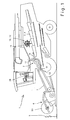
- FIG. 1 The embodiment of the invention shown in FIG. 1 is a self-propelled combine harvester 1 with a so-called tangential threshing mechanism 2 and a downstream Hordechüttler 3 as a separator 4.
- the crop 5 is received by a cutting unit 6, which is the crop 5 a feeder 7 supplies.
- the inclined conveyor 7 transfers the crop 5 to the Tangential threshing unit 2, which mechanically processes the crop.
- the Tangentialdrehisshing unit 2 arrives essentially from threshed stalks existing Gutstrom 10 via the turning drum 11 on the Horden presentler 3, the promotes the flow of material 10 in the rear region of the combine 1. there are still contained in the stream 10 grains, and possibly short straw and Chaff separated.
- Horden Above the Horden oftenlers 3 is a so-called Schüttler Anlagen 12 working loosening and conveying member 13 is arranged, the about a rotational axis 14 transverse to the direction of travel of the combine 1 is driven in rotation counterclockwise.
- the shaker aid 12 loosens the flow of material 10 and supports the promotion of the flow of material 10 on the Horde shakers 3.
- the loosening and Conveying member 13 consists of an approximately closed, about the axis of rotation 14th rotatably driven conveyor drum 15 and a crankshaft arranged therein 16, which is rotatable about the axis of rotation 14 relative to the conveyor drum 15.
- On the Crankshaft 16 are a plurality of conveyor tines 17 rotatably supported by passages 18 protrude in the conveyor drum 15 to the outside.
- the angular orientation of the conveyor tines 17 changes with respect to the conveyor drum 15 to a certain extent, so that the cross section of the Passages 18 corresponding to larger than the cross section of the conveyor tines 17th is executed.
- the length of the conveyor tines 17 is selected so that they do not have the Opening out into the conveyor drum 15 immerse sondem always in the passage 18 are performed.
- the conveyor drum 15 through Reinforced guide elements 19, which removably attached externally on the conveyor drum 15 are.
- the guide elements 19 serve as an improved guide for the same time Feed tines 17 in the passages 18.
- In the area of the guide elements 19 are additionally known per se stripping elements 23 with slots 24 on the Conveyor drum 15 attached.
- the crankshaft 16 is rigidly connected via a support arm 20 with a stub axle 21 which projects outwardly through the end face of the conveyor drum 15, wherein the axis of rotation 22 of the axle stub 21 is aligned with the axis of rotation 14 of the conveyor drum 15.
- an adjusting lever 26 is mounted against rotation at an angle 25 to the support arm 19, at the free end according to the invention designed as a spindle drive 27 actuator 28 is articulated.
- the spindle drive 26 is connected at the other end hingedly connected to the side wall 29 of the combine harvester 1.
- the actuator 28 which is operatively connected to a control unit 37 to be described later, the crankshaft 16 can be rotated continuously about the rotation axis 14 relative to the conveyor drum 15.
- the conveyor tines 17 rotate about the crankshaft 16 on a circular path of movement 30 and are thereby retracted and extended through the passages 18 of the conveyor drum 15 and the slots 24 of the stripping elements 23. If the spindle 31 of the spindle drive 27 moves in or out, the position of the crankshaft 16 and thus also the position of the circular movement path 30 of the conveyor tines 17 are changed relative to the conveyor drum 15 and relative to the tray shaker 3. In this case, the crankshaft 16 is rotated clockwise about the axis of rotation 14 when the spindle 31 of the spindle drive 27 extends and vice versa turned counterclockwise when the spindle 31 enters.
- crankshaft 16 If the crankshaft 16 is rotated clockwise about the axis of rotation 14, it moves upward, causing the trajectory 30 moves away from the Horden yetler 3. Conversely, the trajectory 30 approaches the Horden yetler 3 when the counterclockwise rotated about the rotation axis 14 crankshaft 16 moves downward.
- a cap measuring device 32 Above the conveyor drum 15, a cap measuring device 32 is arranged, with which a on the conveyor drum 15 in the direction of rotation of the conveyor drum 15 funded Erntegutstrom 33 is detected.
- the throw-over measuring device 32 consists in the illustrated embodiment of a pivotable flap 34, which is actuated by the energy of the impacting Erntegutstroms 33.
- a connected to the flap 34 opener 35 generates a position signal O as soon as the flap 34 is pivoted out of a closed position 36.
- the position signal O is transmitted to the control unit 37, which in the presence of a position signal O generates a control command signal S, which is transmitted to the actuator 28.
- the control unit 37 is connected to a control panel 38, via which an operator can enter a preselected position 39 of the movement path 30 and store it in the control unit 37.
- the control unit further input signals X can be supplied, which include information about crop-specific and machine-specific parameters. With respect to the crop parameters, this may be information about crop type, crop throughput, and crop moisture.
- the machine-specific parameters may in particular comprise a wide variety of kinematic parameters of the cutting unit 6 as well as the working members 2, 7 of the combine harvester 1. Specifically, these may be, among other things, threshing device settings such as the threshing drum speed or the size of the threshing slit 52, as well as the height of the reel 53 associated with the cutting unit 6.
- the movement path 30 in Figure 2 is in an upper position 40, wherein the spindle 31 of the spindle drive 27 is fully extended, so that an angle 41 between the adjusting lever 26 and a reference axis 42 has reached a maximum.
- the trajectory 30 of the conveyor tines 17 is removed at a vertical distance 43 of the Horden presentler 3 and the conveyor tines 17 penetrate at a maximum depth 44 in the crop stream 10, wherein they sweep an angle 45 when penetrating the crop flow.
- the conveyor tines 17 raise only an upper layer of the crop stream 10 slightly.
- the upwardly moving conveyor tines 17 are already retracted below a horizontal reference axis 42 in the stripping 23, so that the crop 3 is promoted only slightly upwards.
- the separation efficiency of the Horden—ler 2 is hardly increased in the upper position 40 of the trajectory 28 by the Schüttler Anlagen 5.
- the spindle 31 of the spindle drive 27 moves so far until the trajectory 30 reaches a Matterreserveposition 46, which has a smaller distance to Horden presentler than the preselected position 39th If the throw-measuring device 32 in this Automatreserveposition 42 of the trajectory 30 for a period sensed no position signal O, the spindle 30 extends until the trajectory 28 reaches the preselected position 39.
- the actuator 28 extends at least as far as until the movement path 28 has reached such a position in which further crop rotation by the feed tines 17 is avoided. 3, the conveyor tines 17 and the movement path 30 of the conveyor tines 17 are shown for comparison, when the movement path 30 is pivoted to a lower position 47 and the angle 41 has reached a minimum.
- the movement path 29 of the conveyor tines 17 is located in a compared to the distance 43 (see Figure 2) lower vertical distance 48 to Horden—ler 3. All disposed on the lower half of the conveyor drum 15 conveyor tines 17 protrude beyond the stripping elements 23.
- the conveyor tines 17 engage in comparison to FIG. 2 deeper into the material layer and remain engaged longer, as they pass over an angle at the intervention 50, which is greater than that angle 45 according to an upper position of Figure 2. It should be noted that the material layer thickness of the conveyed on the Horden presentler 3 Gutstroms 10 in Figure 2 and Figure 3 is the same.
- the throw-measuring device 32 consists of a light barrier 51 which is arranged transversely to the direction of rotation above the conveyor drum 15.
- the Gutmit Spotifyintenstician the loosening and conveying member 13 is changeable, on the one hand to loosen the Gutstrom 10 as good as possible, but at the same time to prevent a Erntegutstrom 33 supersaturated on the loosening and conveying member 13 is promoted.
- the Gutmit Cyprusintenstician is on the one hand dependent on the non-positive and the positive connection between the crop stream 10 and the conveyor tines 17.
- the positive connection is stronger, for example, in wet straw than dry straw, the positive connection is stronger in long straw than short straw.
- the Gutmit Cyprusintenstician is influenced by the change in the positive connection between the crop stream 10 and the conveyor tines 17, this can be achieved by changing the penetration depth of the conveyor tines 17 in the crop stream 10 and / or the number of penetrating into the material flow 10 feed tines 17.
- the Gutmit Cyprusintenstician by the change in the frictional connection between the crop flow 10 and the conveyor tines 17 can be influenced, which can be achieved by changing the angle between the conveyor tines 17 and the material flow 10. It is within the skill of one skilled in the art to modify the described embodiments in a manner not shown or to use in other machine systems to achieve the effects described, without departing from the scope of the invention.
Landscapes
- Life Sciences & Earth Sciences (AREA)
- Environmental Sciences (AREA)
- Threshing Machine Elements (AREA)
- Outside Dividers And Delivering Mechanisms For Harvesters (AREA)
- Harvester Elements (AREA)
Abstract
Description
Aus der EP 0 933 017 ist eine als Rotationsförderer ausgeführte Schüttlerhilfe bekannt, die aus einem drehbaren Rotationskörper mit einer nahezu geschlossenen, zylinderförmigen Mantelfläche und mehreren darin exzentrisch und drehbar gelagerten Mitnehmern besteht. Die Mitnehmer sind in Abständen in Richtung der Rotationsachse des Rotationskörpers angeordnet und radial durch Öffnungen in Mitnehmerführungen in der Mantelfläche beweglich. Die Mantelfläche des Rotationskörpers setzt sich aus Metallabdeckungen zusammen, die derart gebogen sind, dass sich radial nach innen versetzte Bereiche ergeben, die parallel zur Rotationsachse des Rotationskörpers verlaufen. Die vorstehenden Teile des Rotationsförderers wie beispielsweise die Mitnehmerführungen sind in den nach innen versetzten Bereichen versenkt, damit die Getreidehalme nicht daran haften bleiben. Befindet sich ein Mitnehmer in einer radial nach innen versetzten Position, dann befindet sich das zugehörige freie Ende des Mitnehmers innerhalb des äußeren Durchmessers des radial nicht versetzten Bereichs des Rotationskörpers. Die Mitnehmer werden bei einem Umlauf des Rotationskörpers durch die Mitnehmerführungen ein- und ausgefahren, dabei greifen sie zur Auflockerung in das auf dem Schüttler beförderte Stroh ein und heben es an, um die Abscheidung der Restkörner zu verbessern. Das Aufreißen der Gutschicht begünstigt zudem das Durchdringen der Körner durch das Stroh. Das an den Mitnehmern anhaftende Erntegut wird beim Einfahren der Mitnehmer an den Mitnehmerführungen abgestreift. Nachteilig bei dem bekannten Rotationsförderer ist, dass nicht verhindert werden kann, das Erntegut über den Rotationsförderer gefördert wird oder sich um den Rotationsförderer wickelt.
Diese Aufgabe wird erfindungsgemäß durch die kennzeichnenden Merkmale des Anspruchs 1 gelöst. Weitere vorteilhafte Wirkungen des Erfindungsgegenstandes ergeben sich aus den Unteransprüchen.
Dadurch, dass die Gutmitnahmeintensität des Auflockerungs- und Förderorgans änderbar ist, kann verhindert werden, dass sich Erntegut um das Förderorgan wickelt oder über das Förderorgan gefördert wird.
- Fig.1
- eine Seitenansicht eines Mähdreschers,
- Fig.2
- eine Ansicht des Auflockerungs- und Förderorgans mit der Bewegungsbahn der Förderzinken in einer oberen Position,
- Fig.3
- eine Ansicht des Auflockerungs- und Förderorgans mit der Bewegungsbahn der Förderzinken in einer unteren Position.
Während eines Umlaufs der Fördertrommel 15 drehen sich die Förderzinken 17 um die Kurbelwelle 16 auf einer kreisförmigen Bewegungsbahn 30 und werden dabei durch die Durchlässe 18 der Fördertrommel 15 und die Schlitze 24 der Abstreifelemente 23 ein- und ausgefahren.
Fährt die Spindel 31 des Spindelantriebs 27 ein oder aus, wird die Lage der Kurbelwelle 16 und damit auch die Lage der kreisförmigen Bewegungsbahn 30 der Förderzinken 17 relativ zur Fördertrommel 15 und relativ zu dem Hordenschüttler 3 verändert. Dabei wird die Kurbelwelle 16 im Uhrzeigersinn um die Drehachse 14 gedreht, wenn die Spindel 31 des Spindelantriebs 27 ausfährt und umgekehrt entgegen dem Uhrzeigersinn gedreht, wenn die Spindel 31 einfährt. Wird die Kurbelwelle 16 im Uhrzeigersinn um die Drehachse 14 gedreht, bewegt sie sich nach oben, wodurch sich die Bewegungsbahn 30 vom Hordenschüttler 3 weg bewegt. Umgekehrt nähert sich die Bewegungsbahn 30 dem Hordenschüttler 3, wenn die entgegen dem Uhrzeigersinn um die Drehachse 14 gedrehte Kurbelwelle 16 sich nach unten bewegt.
Oberhalb der Fördertrommel 15 ist eine Überwurfmesseinrichtung 32 angeordnet, mit der ein über die Fördertrommel 15 in Drehrichtung der Fördertrommel 15 geförderter Erntegutstrom 33 detektiert wird. Die Überwurfmesseinrichtung 32 besteht im dargestellten Ausführungsbeispiel aus einer schwenkbaren Klappe 34, die durch die Energie des aufprallenden Erntegutstroms 33 betätigt wird. Ein an der Klappe 34 angeschlossener Öffner 35 generiert ein Stellungssignal O sobald die Klappe 34 aus einer geschlossenen Position 36 heraus verschwenkt ist. Das Stellungssignal O wird an die Steuereinheit 37 übertragen, welche bei Vorhandensein eines Stellungssignals O ein Steuerbefehlssignal S generiert, das an das Stellglied 28 übermittelt wird. Die Steuereinheit 37 ist mit einem Bedienfeld 38 verbunden, über das ein Bediener eine vorgewählte Position 39 der Bewegungsbahn 30 eingeben und in der Steuereinheit 37 abspeichern kann. In vorteilhafter Weiterbildung der Erfindung können der Steuereinheit weitere Eingangssignale X zugeführt werden, die Informationen über erntegutspezifische sowie maschinenspezifische Parameter umfassen. Bezüglich der Erntegutparameter können dies Informationen zur Erntegutart, dem Erntegutdurchsatz sowie der Erntegutfeuchte sein. Die maschinenspezifischen Parameter können insbesondere verschiedenste kinematische Parameter des Schneidwerks 6 sowie der Arbeitsorgane 2, 7 des Mähdreschers 1 umfassen. Im Einzelnen können dies unter anderem Dreschwerkseinstellungen wie etwa die Dreschtrommeldrehzahl oder die Größe des Dreschspaltes 52 sowie die Höhe der dem Schneidwerk 6 zugeordneten Haspel 53 sein.
Sobald die Überwurfmesseinrichtung 32 jedoch einen Erntegutstrom 33 sensiert, fährt das Stellglied 28 zumindest soweit aus, bis die Bewegungsbahn 28 eine solche Position erreicht hat, bei der eine weitere Gutmitnahme durch die Förderzinken 17 unterbleibt.
In der Fig.3 sind zum Vergleich die Förderzinken 17 und die Bewegungsbahn 30 der Förderzinken 17 dargestellt, wenn die Bewegungsbahn 30 in eine untere Position 47 verschwenkt ist und der Winkel 41 ein Minimum erreicht hat.
In Fig.3 ist zudem ein alternatives Ausführungsbeispiel dargestellt, bei dem die Überwurfmesseinrichtung 32 aus einer Lichtschranke 51 besteht, die quer zur Drehrichtung oberhalb der Fördertrommel 15 angeordnet ist.
Bei dem erfindungsgemäßen Mähdrescher 1 ist die Gutmitnahmeintensität des Auflockerungs- und Förderorgan 13 änderbar, um einerseits den Gutstrom 10 so gut wie möglich aufzulockern jedoch gleichzeitig zu verhindern, dass ein Erntegutstrom 33 oberschlächtig über das Auflockerungs- und Förderorgan 13 gefördert wird.
Die Gutmitnahmeintensität ist dabei einerseits abhängig von der kraftschlüssigen sowie der formschlüssigen Verbindung zwischen dem Gutstrom 10 und den Förderzinken 17. Die kraftschlüssige Verbindung ist beispielweise bei feuchtem Stroh stärker ist als bei trockenem Stroh, die formschlüssige Verbindung ist bei langem Stroh stärker ist als bei Kurzstroh.
Die Gutmitnahmeintensität ist durch die Änderung des Formschlusses zwischen dem Gutstrom 10 und den Förderzinken 17 beeinflussbar, dies kann durch eine Veränderung der Eindringtiefe der Förderzinken 17 in den Gutstrom 10 und/oder der Anzahl der in den Gutstrom 10 eindringenden Förderzinken 17 erreicht werden.
Zudem ist die Gutmitnahmeintensität durch die Änderung des Kraftschlusses zwischen dem Gutstrom 10 und den Förderzinken 17 beeinflussbar ist, was durch eine Änderung des Winkels zwischen den Förderzinken 17 und dem Gutstrom 10 erreicht werden kann.
Es liegt im Rahmen des Könnens eines Fachmannes die beschriebenen Ausführungsbeispiele in nicht dargestellter Weise abzuwandeln oder in anderen Maschinensystemen einzusetzen, um die beschriebenen Effekte zu erzielen, ohne dabei den Rahmen der Erfindung zu verlassen.
- 1
- Mähdrescher
- 2
- Tangentialdreschwerk
- 3
- Hordenschüttler
- 4
- Abscheideeinrichtung
- 5
- Erntegut
- 6
- Schneidwerk
- 7
- Schrägförderer
- 9 10
- Gutstrom
- 11
- Wendetrommel
- 12
- Schüttlerhilfe
- 13
- Auflockerungs- und Förderorgan
- 14
- Drehachse
- 15
- Fördertrommel
- 16
- Kurbelwelle
- 17
- Förderzinken
- 18
- Durchlass
- 19
- Führungselemente
- 20
- Tragarm
- 21
- Achsstummel
- 22
- Drehachse
- 23
- Abstreifelement
- 24
- Schlitz
- 25
- Winkel
- 26
- Verstellhebel
- 27
- Spindelantrieb
- 28
- Stellglied
- 29
- Seitenwand
- 30
- Bewegungsbahn
- 31
- Spindel
- 32
- Überwurfmesseinrichtung
- 33
- Erngutstrom
- 34
- Klappe
- 35
- Öffner
- 36
- geschlossene Position
- 37
- Steuereinheit
- 38
- Bedienfeld
- 39
- vorgewählte Position
- 40
- obere Position
- 41
- Winkel
- 42
- Bezugsachse
- 43
- Lotrechter Abstand
- 44
- Tiefe
- 45
- Winkel
- 46
- Überwurfreserveposition
- 47
- untere Position
- 48
- lotrechter Abstand
- 49
- Tiefe
- 50
- Winkel
- 51
- Lichtschranke
- 52
- Dreschspalt
- 53
- Haspel
- O
- Stellungssignal
- S
- Steuerbefehlssignal
- X
- Eingangssignal
Claims (16)
- Mähdrescher mit einer Abscheideeinrichtung (4) zur Abscheidung eines Gutstroms von einem vorwiegend Erntegutreste enthaltenen Gutstrom (10) und wenigstens einem oberhalb der Abscheideeinrichtung (4) angeordneten Auflockerungs- und Förderorgan (13) zur Auflockerung des Gutstroms (10) auf dem Abscheideorgan (4), das wenigstens eine rotierende Fördertrommel (15) umfasst, an der Förderzinken (17) relativ beweglich zur Fördertrommel (15) angeordnet sind
dadurch gekennzeichnet, dass die Gutmitnahmeintensität des Auflockerungs- und Förderorgans (13) änderbar ist. - Mähdrescher nach Anspruch 1,
dadurch gekennzeichnet, dass die Gutmitnahmeintensität durch die Änderung des Formschlusses und/oder Kraftschlusses zwischen dem Gutstrom (10) und den Förderzinken (17) beeinflussbar ist. - Mähdrescher nach einem der vorhergehenden Ansprüche,
dadurch gekennzeichnet, dass die Gutmitnahmeintensität durch die Änderung der Drehzahl des Auflockerungs- und Förderorgans (13) beeinflussbar ist. - Mähdrescher nach einem der vorhergehenden Ansprüche,
dadurch gekennzeichnet, dass die Förderzinken (17) auf einer kreisförmigen Bewegungsbahn (30) umlaufen, deren Lage relativ zur Fördertrommel (15) änderbar ist. - Mähdrescher nach einem der vorhergehenden Ansprüche,
dadurch gekennzeichnet, dass die Gutmitnahmeintensität mit einer Überwurfmesseinrichtung (32) ermittelt wird, die oberhalb der Fördertrommel (15) angeordnet ist. - Mähdrescher nach einem der vorhergehenden Ansprüche,
dadurch gekennzeichnet, dass die Überwurfmesseinrichtung (32) einen in Drehrichtung der Fördertrommel (15) über die Fördertrommel (15) hinweg geförderten Erntegutstrom (33) ermittelt. - Mähdrescher nach einem der vorhergehenden Ansprüche,
dadurch gekennzeichnet, dass die Überwurfmesseinrichtung (33) aus wenigstens einer drehbar gelagerten Klappe (34) besteht, die durch den Aufprall des Erntegutstroms (33) verschwenkt wird. - Mähdrescher nach Anspruch 7,
dadurch gekennzeichnet, dass der Klappe (34) ein Öffner (35) zugeordnet ist, der ein Signal (O) generiert, sobald sich die Klappe (34) außerhalb einer Schließposition (36) befindet. - Mähdrescher nach einem der vorhergehenden Ansprüche,
dadurch gekennzeichnet, dass die Überwurfmesseinrichtung (32) aus wenigstens einer Lichtschranke (51) besteht und wobei die Lichtschranke (51) quer zur Drehrichtung der Fördertrommel (15) angeordnet ist. - Mähdrescher nach einem der vorhergehenden Ansprüche,
dadurch gekennzeichnet, dass die Lage der Bewegungsbahn (30) der Förderzinken (17) über ein Stellglied (28) änderbar ist. - Mähdrescher nach einem der vorhergehenden Ansprüche,
dadurch gekennzeichnet, dass das Stellglied (28) und die Überwurfmesseinrichtung (32) mit einer Steuereinheit (37) verbunden sind. - Mähdrescher nach einem der vorhergehenden Ansprüche,
dadurch gekennzeichnet, dass die Steuereinheit (37) das Stellsignal (S) in Abhängigkeit von einem oder mehreren Erntegutparametern oder Maschinenparametern generiert. - Mähdrescher nach Anspruch 12,
dadurch gekennzeichnet, dass die Erntegutparameter die Erntegutart, der Erntegutdurchsatz und die Erntegutfeuchte sein können. - Mähdrescher nach Anspruch 12,
dadurch gekennzeichnet, dass die Maschinenparameter kinematische Parameter des Schneidwerks (6) und kinematische Parameter der Arbeitsorgane (2, 7, 11) sein können. - Mähdrescher nach einem der vorhergehenden Ansprüche,
dadurch gekennzeichnet, dass die Bewegungsbahn (30) bis zu einer Überwurfreserveposition (46) verstellt wird, die eine vorgewählte Position (39) unterschreitet und das die Bewegungsbahn (30) anschließend in die vorgewählte Position (39) verstellt wird, wenn die Überwurfmesseinrichtung (32) in der Überwurfreserveposition (46) für einen Zeitraum keinen Erntegutstrom (33) sensiert. - Mähdrescher nach einem der vorhergehenden Ansprüche,
dadurch gekennzeichnet, dass, das Stellglied (28) bei Sensierung eines Erntegutstromes (33) durch die Überwurfmesseinrichtung (32) zumindest soweit ausfährt, bis die Bewegungsbahn (30) eine obere Position (40) erreicht, in der die Überwurfmesseinrichtung (32) keinen Erntegutstrom (33) mehr sensiert.
Applications Claiming Priority (2)
| Application Number | Priority Date | Filing Date | Title |
|---|---|---|---|
| DE102004031054A DE102004031054A1 (de) | 2004-06-25 | 2004-06-25 | Schüttlerhilfe an einem Mähdrescher |
| DE102004031054 | 2004-06-25 |
Publications (2)
| Publication Number | Publication Date |
|---|---|
| EP1609353A1 true EP1609353A1 (de) | 2005-12-28 |
| EP1609353B1 EP1609353B1 (de) | 2008-03-26 |
Family
ID=34936471
Family Applications (1)
| Application Number | Title | Priority Date | Filing Date |
|---|---|---|---|
| EP05010409A Expired - Lifetime EP1609353B1 (de) | 2004-06-25 | 2005-05-13 | Schüttlerhilfe an einem Mähdrescher |
Country Status (3)
| Country | Link |
|---|---|
| EP (1) | EP1609353B1 (de) |
| AT (1) | ATE390042T1 (de) |
| DE (2) | DE102004031054A1 (de) |
Cited By (2)
| Publication number | Priority date | Publication date | Assignee | Title |
|---|---|---|---|---|
| EP1961289A1 (de) * | 2007-02-22 | 2008-08-27 | CLAAS Selbstfahrende Erntemaschinen GmbH | Landwirtschaftliche Arbeitsmaschine |
| EP2103204A1 (de) * | 2008-03-20 | 2009-09-23 | CLAAS Selbstfahrende Erntemaschinen GmbH | Mähdrescher |
Citations (3)
| Publication number | Priority date | Publication date | Assignee | Title |
|---|---|---|---|---|
| EP0567192A1 (de) * | 1992-04-24 | 1993-10-27 | New Holland Belgium N.V. | Verstellung der Position eines Excenters zur Steuerung Einzugsschneckenfinger |
| EP0933017A1 (de) | 1998-01-29 | 1999-08-04 | Deere & Company | Rotationsförderer mit einem Rotationskörper und wenigstens einem Mitnehmer und Erntemaschine mit einem solchen Rotationsförderer |
| US6190253B1 (en) * | 1997-03-07 | 2001-02-20 | Deere & Company | Straw walkers having a supplemental rotary separator |
-
2004
- 2004-06-25 DE DE102004031054A patent/DE102004031054A1/de not_active Withdrawn
-
2005
- 2005-05-13 AT AT05010409T patent/ATE390042T1/de not_active IP Right Cessation
- 2005-05-13 DE DE502005003417T patent/DE502005003417D1/de not_active Expired - Lifetime
- 2005-05-13 EP EP05010409A patent/EP1609353B1/de not_active Expired - Lifetime
Patent Citations (3)
| Publication number | Priority date | Publication date | Assignee | Title |
|---|---|---|---|---|
| EP0567192A1 (de) * | 1992-04-24 | 1993-10-27 | New Holland Belgium N.V. | Verstellung der Position eines Excenters zur Steuerung Einzugsschneckenfinger |
| US6190253B1 (en) * | 1997-03-07 | 2001-02-20 | Deere & Company | Straw walkers having a supplemental rotary separator |
| EP0933017A1 (de) | 1998-01-29 | 1999-08-04 | Deere & Company | Rotationsförderer mit einem Rotationskörper und wenigstens einem Mitnehmer und Erntemaschine mit einem solchen Rotationsförderer |
Cited By (3)
| Publication number | Priority date | Publication date | Assignee | Title |
|---|---|---|---|---|
| EP1961289A1 (de) * | 2007-02-22 | 2008-08-27 | CLAAS Selbstfahrende Erntemaschinen GmbH | Landwirtschaftliche Arbeitsmaschine |
| RU2460271C2 (ru) * | 2007-02-22 | 2012-09-10 | КЛААС Зельбстфаренде Эрнтемашинен ГмбХ | Сельскохозяйственная рабочая машина |
| EP2103204A1 (de) * | 2008-03-20 | 2009-09-23 | CLAAS Selbstfahrende Erntemaschinen GmbH | Mähdrescher |
Also Published As
| Publication number | Publication date |
|---|---|
| DE502005003417D1 (de) | 2008-05-08 |
| ATE390042T1 (de) | 2008-04-15 |
| EP1609353B1 (de) | 2008-03-26 |
| DE102004031054A1 (de) | 2006-01-19 |
Similar Documents
| Publication | Publication Date | Title |
|---|---|---|
| DE2628414C2 (de) | ||
| EP1106049B1 (de) | Einzugs- und Pflückeinrichtung mit Häckseleinrichtung | |
| EP0933017B1 (de) | Rotationsförderer mit einem Rotationskörper und wenigstens einem Mitnehmer und Erntemaschine mit einem solchen Rotationsförderer | |
| EP0824856B1 (de) | Maschine zum reihenunabhängigen Mähen und Häckseln von Mais und dgl. stengelartigem Erntegut | |
| EP1106048B1 (de) | Einzugs- und Pflückeinrichtung einer Erntegutbergungsvorrichtung | |
| EP1161857B1 (de) | Einzugs- und Pflückeinrichtung | |
| DE2433948A1 (de) | Ernte- und dreschmaschine | |
| WO2001011940A1 (de) | Stellanordnung für die zinkenträger einer haspel für ein schneidwerk | |
| DE102005038553A1 (de) | Verfahren zum Überladen von Erntegut | |
| DE2462568A1 (de) | Dreschmaschine, insbesondere maehdrescher | |
| DE2729033A1 (de) | Maehdrescher | |
| DE2729012A1 (de) | Maehdrescher | |
| EP3203829B1 (de) | Vorrichtung zum bearbeiten von erntegut und verfahren zum steuern eines erntegutflusses in der vorrichtung | |
| EP3228174B1 (de) | Wurfrotor einer gutverteileinrichtung für eine selbstfahrende erntemaschine | |
| DE2118914A1 (de) | Aus wenigstens einem Paar zusammenwirkender Mähkreisel bestehendes Mähwerk und nachgeschaltetem Quetschwalzenpaar bestehende Halmgutaufbereitungsmaschine | |
| EP0503468A1 (de) | Schneidwerk für Mähdrescher | |
| EP0862849B1 (de) | Gutbearbeitungsvorrichtung | |
| DE19916645A1 (de) | Fördererzusammenbau | |
| DE2503693A1 (de) | Kornabscheidevorrichtung fuer einen maehdrescher | |
| EP1609353B1 (de) | Schüttlerhilfe an einem Mähdrescher | |
| DE69119407T2 (de) | Ablenkungsvorrichtung vor der Dreschvorrichtung eines Mähdreschers | |
| DE3329276A1 (de) | Futtererntemaschine mit seitlicher foerderung | |
| DE69121086T2 (de) | Steinauffangvorrichtung für Mähdrescher | |
| DE4209020C2 (de) | Trennvorrichtung | |
| EP0862850A1 (de) | Mähdrescher |
Legal Events
| Date | Code | Title | Description |
|---|---|---|---|
| PUAI | Public reference made under article 153(3) epc to a published international application that has entered the european phase |
Free format text: ORIGINAL CODE: 0009012 |
|
| AK | Designated contracting states |
Kind code of ref document: A1 Designated state(s): AT BE BG CH CY CZ DE DK EE ES FI FR GB GR HU IE IS IT LI LT LU MC NL PL PT RO SE SI SK TR |
|
| AX | Request for extension of the european patent |
Extension state: AL BA HR LV MK YU |
|
| 17P | Request for examination filed |
Effective date: 20060628 |
|
| AKX | Designation fees paid |
Designated state(s): AT BE BG CH CY CZ DE DK EE ES FI FR GB GR HU IE IS IT LI LT LU MC NL PL PT RO SE SI SK TR |
|
| 17Q | First examination report despatched |
Effective date: 20061010 |
|
| GRAP | Despatch of communication of intention to grant a patent |
Free format text: ORIGINAL CODE: EPIDOSNIGR1 |
|
| GRAS | Grant fee paid |
Free format text: ORIGINAL CODE: EPIDOSNIGR3 |
|
| GRAA | (expected) grant |
Free format text: ORIGINAL CODE: 0009210 |
|
| AK | Designated contracting states |
Kind code of ref document: B1 Designated state(s): AT BE BG CH CY CZ DE DK EE ES FI FR GB GR HU IE IS IT LI LT LU MC NL PL PT RO SE SI SK TR |
|
| REG | Reference to a national code |
Ref country code: GB Ref legal event code: FG4D Free format text: NOT ENGLISH |
|
| REG | Reference to a national code |
Ref country code: IE Ref legal event code: FG4D Free format text: LANGUAGE OF EP DOCUMENT: GERMAN Ref country code: CH Ref legal event code: EP |
|
| REF | Corresponds to: |
Ref document number: 502005003417 Country of ref document: DE Date of ref document: 20080508 Kind code of ref document: P |
|
| REG | Reference to a national code |
Ref country code: DE Ref legal event code: R096 Ref document number: 502005003417 Country of ref document: DE Effective date: 20080508 |
|
| PG25 | Lapsed in a contracting state [announced via postgrant information from national office to epo] |
Ref country code: FI Free format text: LAPSE BECAUSE OF FAILURE TO SUBMIT A TRANSLATION OF THE DESCRIPTION OR TO PAY THE FEE WITHIN THE PRESCRIBED TIME-LIMIT Effective date: 20080326 |
|
| NLV1 | Nl: lapsed or annulled due to failure to fulfill the requirements of art. 29p and 29m of the patents act | ||
| PG25 | Lapsed in a contracting state [announced via postgrant information from national office to epo] |
Ref country code: PL Free format text: LAPSE BECAUSE OF FAILURE TO SUBMIT A TRANSLATION OF THE DESCRIPTION OR TO PAY THE FEE WITHIN THE PRESCRIBED TIME-LIMIT Effective date: 20080326 Ref country code: SI Free format text: LAPSE BECAUSE OF FAILURE TO SUBMIT A TRANSLATION OF THE DESCRIPTION OR TO PAY THE FEE WITHIN THE PRESCRIBED TIME-LIMIT Effective date: 20080326 |
|
| REG | Reference to a national code |
Ref country code: IE Ref legal event code: FD4D |
|
| PG25 | Lapsed in a contracting state [announced via postgrant information from national office to epo] |
Ref country code: ES Free format text: LAPSE BECAUSE OF FAILURE TO SUBMIT A TRANSLATION OF THE DESCRIPTION OR TO PAY THE FEE WITHIN THE PRESCRIBED TIME-LIMIT Effective date: 20080707 Ref country code: SE Free format text: LAPSE BECAUSE OF FAILURE TO SUBMIT A TRANSLATION OF THE DESCRIPTION OR TO PAY THE FEE WITHIN THE PRESCRIBED TIME-LIMIT Effective date: 20080626 Ref country code: PT Free format text: LAPSE BECAUSE OF FAILURE TO SUBMIT A TRANSLATION OF THE DESCRIPTION OR TO PAY THE FEE WITHIN THE PRESCRIBED TIME-LIMIT Effective date: 20080901 Ref country code: SK Free format text: LAPSE BECAUSE OF FAILURE TO SUBMIT A TRANSLATION OF THE DESCRIPTION OR TO PAY THE FEE WITHIN THE PRESCRIBED TIME-LIMIT Effective date: 20080326 Ref country code: CZ Free format text: LAPSE BECAUSE OF FAILURE TO SUBMIT A TRANSLATION OF THE DESCRIPTION OR TO PAY THE FEE WITHIN THE PRESCRIBED TIME-LIMIT Effective date: 20080326 |
|
| PG25 | Lapsed in a contracting state [announced via postgrant information from national office to epo] |
Ref country code: NL Free format text: LAPSE BECAUSE OF FAILURE TO SUBMIT A TRANSLATION OF THE DESCRIPTION OR TO PAY THE FEE WITHIN THE PRESCRIBED TIME-LIMIT Effective date: 20080326 Ref country code: RO Free format text: LAPSE BECAUSE OF FAILURE TO SUBMIT A TRANSLATION OF THE DESCRIPTION OR TO PAY THE FEE WITHIN THE PRESCRIBED TIME-LIMIT Effective date: 20080326 |
|
| BERE | Be: lapsed |
Owner name: CLAAS SELBSTFAHRENDE ERNTEMASCHINEN G.M.B.H. Effective date: 20080531 |
|
| ET | Fr: translation filed | ||
| PG25 | Lapsed in a contracting state [announced via postgrant information from national office to epo] |
Ref country code: IS Free format text: LAPSE BECAUSE OF FAILURE TO SUBMIT A TRANSLATION OF THE DESCRIPTION OR TO PAY THE FEE WITHIN THE PRESCRIBED TIME-LIMIT Effective date: 20080726 Ref country code: MC Free format text: LAPSE BECAUSE OF NON-PAYMENT OF DUE FEES Effective date: 20080531 |
|
| PG25 | Lapsed in a contracting state [announced via postgrant information from national office to epo] |
Ref country code: EE Free format text: LAPSE BECAUSE OF FAILURE TO SUBMIT A TRANSLATION OF THE DESCRIPTION OR TO PAY THE FEE WITHIN THE PRESCRIBED TIME-LIMIT Effective date: 20080326 Ref country code: DK Free format text: LAPSE BECAUSE OF FAILURE TO SUBMIT A TRANSLATION OF THE DESCRIPTION OR TO PAY THE FEE WITHIN THE PRESCRIBED TIME-LIMIT Effective date: 20080326 Ref country code: LT Free format text: LAPSE BECAUSE OF FAILURE TO SUBMIT A TRANSLATION OF THE DESCRIPTION OR TO PAY THE FEE WITHIN THE PRESCRIBED TIME-LIMIT Effective date: 20080326 Ref country code: IE Free format text: LAPSE BECAUSE OF FAILURE TO SUBMIT A TRANSLATION OF THE DESCRIPTION OR TO PAY THE FEE WITHIN THE PRESCRIBED TIME-LIMIT Effective date: 20080326 |
|
| PLBE | No opposition filed within time limit |
Free format text: ORIGINAL CODE: 0009261 |
|
| STAA | Information on the status of an ep patent application or granted ep patent |
Free format text: STATUS: NO OPPOSITION FILED WITHIN TIME LIMIT |
|
| 26N | No opposition filed |
Effective date: 20081230 |
|
| PG25 | Lapsed in a contracting state [announced via postgrant information from national office to epo] |
Ref country code: BE Free format text: LAPSE BECAUSE OF NON-PAYMENT OF DUE FEES Effective date: 20080531 |
|
| REG | Reference to a national code |
Ref country code: DE Ref legal event code: R097 Ref document number: 502005003417 Country of ref document: DE Effective date: 20081230 |
|
| PG25 | Lapsed in a contracting state [announced via postgrant information from national office to epo] |
Ref country code: BG Free format text: LAPSE BECAUSE OF FAILURE TO SUBMIT A TRANSLATION OF THE DESCRIPTION OR TO PAY THE FEE WITHIN THE PRESCRIBED TIME-LIMIT Effective date: 20080626 |
|
| PG25 | Lapsed in a contracting state [announced via postgrant information from national office to epo] |
Ref country code: AT Free format text: LAPSE BECAUSE OF NON-PAYMENT OF DUE FEES Effective date: 20080513 |
|
| PG25 | Lapsed in a contracting state [announced via postgrant information from national office to epo] |
Ref country code: CY Free format text: LAPSE BECAUSE OF FAILURE TO SUBMIT A TRANSLATION OF THE DESCRIPTION OR TO PAY THE FEE WITHIN THE PRESCRIBED TIME-LIMIT Effective date: 20080326 |
|
| REG | Reference to a national code |
Ref country code: CH Ref legal event code: PL |
|
| PG25 | Lapsed in a contracting state [announced via postgrant information from national office to epo] |
Ref country code: LI Free format text: LAPSE BECAUSE OF NON-PAYMENT OF DUE FEES Effective date: 20090531 Ref country code: CH Free format text: LAPSE BECAUSE OF NON-PAYMENT OF DUE FEES Effective date: 20090531 |
|
| PG25 | Lapsed in a contracting state [announced via postgrant information from national office to epo] |
Ref country code: HU Free format text: LAPSE BECAUSE OF FAILURE TO SUBMIT A TRANSLATION OF THE DESCRIPTION OR TO PAY THE FEE WITHIN THE PRESCRIBED TIME-LIMIT Effective date: 20080927 Ref country code: LU Free format text: LAPSE BECAUSE OF NON-PAYMENT OF DUE FEES Effective date: 20080513 |
|
| PG25 | Lapsed in a contracting state [announced via postgrant information from national office to epo] |
Ref country code: TR Free format text: LAPSE BECAUSE OF FAILURE TO SUBMIT A TRANSLATION OF THE DESCRIPTION OR TO PAY THE FEE WITHIN THE PRESCRIBED TIME-LIMIT Effective date: 20080326 |
|
| PG25 | Lapsed in a contracting state [announced via postgrant information from national office to epo] |
Ref country code: GR Free format text: LAPSE BECAUSE OF FAILURE TO SUBMIT A TRANSLATION OF THE DESCRIPTION OR TO PAY THE FEE WITHIN THE PRESCRIBED TIME-LIMIT Effective date: 20080627 |
|
| REG | Reference to a national code |
Ref country code: FR Ref legal event code: PLFP Year of fee payment: 12 |
|
| REG | Reference to a national code |
Ref country code: FR Ref legal event code: PLFP Year of fee payment: 13 |
|
| REG | Reference to a national code |
Ref country code: FR Ref legal event code: PLFP Year of fee payment: 14 |
|
| PGFP | Annual fee paid to national office [announced via postgrant information from national office to epo] |
Ref country code: DE Payment date: 20180328 Year of fee payment: 14 |
|
| PGFP | Annual fee paid to national office [announced via postgrant information from national office to epo] |
Ref country code: NL Payment date: 20180523 Year of fee payment: 14 |
|
| PGFP | Annual fee paid to national office [announced via postgrant information from national office to epo] |
Ref country code: GB Payment date: 20180518 Year of fee payment: 14 |
|
| REG | Reference to a national code |
Ref country code: DE Ref legal event code: R119 Ref document number: 502005003417 Country of ref document: DE |
|
| GBPC | Gb: european patent ceased through non-payment of renewal fee |
Effective date: 20190513 |
|
| PG25 | Lapsed in a contracting state [announced via postgrant information from national office to epo] |
Ref country code: GB Free format text: LAPSE BECAUSE OF NON-PAYMENT OF DUE FEES Effective date: 20190513 Ref country code: DE Free format text: LAPSE BECAUSE OF NON-PAYMENT OF DUE FEES Effective date: 20191203 |
|
| PG25 | Lapsed in a contracting state [announced via postgrant information from national office to epo] |
Ref country code: FR Free format text: LAPSE BECAUSE OF NON-PAYMENT OF DUE FEES Effective date: 20190531 |
|
| P01 | Opt-out of the competence of the unified patent court (upc) registered |
Effective date: 20230512 |
|
| PGFP | Annual fee paid to national office [announced via postgrant information from national office to epo] |
Ref country code: IT Payment date: 20240524 Year of fee payment: 20 |