EP1608946B1 - Method and device for control of the capacity of a compressor - Google Patents
Method and device for control of the capacity of a compressor Download PDFInfo
- Publication number
- EP1608946B1 EP1608946B1 EP04704376A EP04704376A EP1608946B1 EP 1608946 B1 EP1608946 B1 EP 1608946B1 EP 04704376 A EP04704376 A EP 04704376A EP 04704376 A EP04704376 A EP 04704376A EP 1608946 B1 EP1608946 B1 EP 1608946B1
- Authority
- EP
- European Patent Office
- Prior art keywords
- compressor
- pressure
- air
- pressure tank
- time
- Prior art date
- Legal status (The legal status is an assumption and is not a legal conclusion. Google has not performed a legal analysis and makes no representation as to the accuracy of the status listed.)
- Expired - Lifetime
Links
- 238000000034 method Methods 0.000 title claims abstract description 33
- 238000004364 calculation method Methods 0.000 abstract description 2
- 238000012360 testing method Methods 0.000 description 17
- 230000008929 regeneration Effects 0.000 description 6
- 238000011069 regeneration method Methods 0.000 description 6
- 230000008878 coupling Effects 0.000 description 4
- 238000010168 coupling process Methods 0.000 description 4
- 238000005859 coupling reaction Methods 0.000 description 4
- 238000001035 drying Methods 0.000 description 4
- 238000005086 pumping Methods 0.000 description 4
- 238000005259 measurement Methods 0.000 description 3
- 230000000977 initiatory effect Effects 0.000 description 2
- 230000006835 compression Effects 0.000 description 1
- 238000007906 compression Methods 0.000 description 1
- 230000006866 deterioration Effects 0.000 description 1
- 239000007789 gas Substances 0.000 description 1
- 230000001788 irregular Effects 0.000 description 1
- 238000012986 modification Methods 0.000 description 1
- 230000004048 modification Effects 0.000 description 1
- 238000012544 monitoring process Methods 0.000 description 1
- 239000002699 waste material Substances 0.000 description 1
- XLYOFNOQVPJJNP-UHFFFAOYSA-N water Substances O XLYOFNOQVPJJNP-UHFFFAOYSA-N 0.000 description 1
Images

Classifications
-
- F—MECHANICAL ENGINEERING; LIGHTING; HEATING; WEAPONS; BLASTING
- F04—POSITIVE - DISPLACEMENT MACHINES FOR LIQUIDS; PUMPS FOR LIQUIDS OR ELASTIC FLUIDS
- F04B—POSITIVE-DISPLACEMENT MACHINES FOR LIQUIDS; PUMPS
- F04B49/00—Control, e.g. of pump delivery, or pump pressure of, or safety measures for, machines, pumps, or pumping installations, not otherwise provided for, or of interest apart from, groups F04B1/00 - F04B47/00
- F04B49/06—Control using electricity
- F04B49/065—Control using electricity and making use of computers
-
- F—MECHANICAL ENGINEERING; LIGHTING; HEATING; WEAPONS; BLASTING
- F04—POSITIVE - DISPLACEMENT MACHINES FOR LIQUIDS; PUMPS FOR LIQUIDS OR ELASTIC FLUIDS
- F04B—POSITIVE-DISPLACEMENT MACHINES FOR LIQUIDS; PUMPS
- F04B51/00—Testing machines, pumps, or pumping installations
-
- F—MECHANICAL ENGINEERING; LIGHTING; HEATING; WEAPONS; BLASTING
- F04—POSITIVE - DISPLACEMENT MACHINES FOR LIQUIDS; PUMPS FOR LIQUIDS OR ELASTIC FLUIDS
- F04B—POSITIVE-DISPLACEMENT MACHINES FOR LIQUIDS; PUMPS
- F04B2207/00—External parameters
- F04B2207/04—Settings
- F04B2207/043—Settings of time
Definitions
- the present invention relates to a method for control of the capacity of an air compressor and a device for performing the capacity test.
- US2782637A describes an apparatus for testing compressors.
- US4676095A describes an apparatus for measuring the work produced by a compressor.
- US5811669A describes a method for calculating flow of compressed gases.
- the object of the invention is to provide a method for checking the capacity of a compressor in a simple and reliable manner.
- the invention also incorporates a device comprising as few contained parts as possible for carrying out the check of the capacity of a compressor.
- capacity of a compressor here denotes the quantity of air which the compressor delivers per unit of time at a given compressor speed and ⁇ counterpressure.
- the compressor capacity is able to be checked in a simple and reliable manner.
- the advantage with this is that it is easy to check in the workshops when a change of compressor should be made.
- the compressor capacity in the vehicle is checked by air being allowed to flow out from the pressure tank through an opening of known geometry. Following a calculation, the quantity of evacuated air is established. After this, the compressor pumps back up to the initial pressure in the pressure tank. The compressor capacity is obtained by comparing the time it takes for the compressor to pump back up to the initial pressure with the time it takes when an acceptable compressor pumps the same quantity of air.
- the air is allowed to flow out from the pressure tank for a set period.
- the quantity of evacuated air is calculated.
- the compressor pumps back up to the initial pressure in the pressure tank and the time it takes to pump this known quantity of air is compared with a time value in order to evaluate the compressor capacity.
- the pressure is allowed to drop between two predefined pressures. The time which the pressure takes to drop is measured and the discharged quantity of air subsequently calculated. After this, the compressor pumps back up to the initial pressure in the pressure tank. The time it takes to pump this known quantity of air is compared with a reference value in order to evaluate the compressor capacity.
- a check is made that the pressure in the pressure tank lies within a predefined pressure range for a predefined time. This check enables a leakage of air from the compressed air system or to other reservoirs to be detected. Air leakage from the pressure tank renders the capacity check ineffectual.
- a traditional air dryer according to fig. 1 has a so-called off-line regeneration.
- the air which is pumped out from a compressor 1 deposits water droplets, which means that the air dryer 7 is exposed to moisture.
- the air dryer 7 has to be dried with dry air.
- the compressor 1, with incorporated motor 2 supplies compressed air to the air dryer 7 through a conduit 4.
- the air dryer 7 is in turn coupled, by a conduit 5, to a separate tank 8, constituting a regeneration tank containing dry air.
- the pressure tank 3 represents the compressed-air-consuming system in the vehicle.
- a valve 11 on the air dryer is opened in order thereby to reduce the pressure and terminate the pumping. Should the system also contain a control conduit 9 for relieving the compressor, this conduit, too, is activated.
- the air in the regeneration tank 8 is thereafter fed back through the air dryer 7 for drying of the drying mass in the air dryer 7. After this, it is possible to reuse the air dryer 7.
- the air dryer 7 has a pneumatic control unit 12 and the air dryer also often incorporates a pneumatic control signal which runs via the control conduit 9 disposed between the air dryer 7 and the compressor 1. This pneumatic control signal enables the pumping of the compressor to be shut off, so that the pumping of air can be started and stopped in a controlled manner.
- An electrically controlled air dryer has a so-called in-line regeneration according to fig. 2 for the purpose of drying the air, which means that a by-pass coupling 14 is used instead of the regeneration tank used in a traditional air dryer.
- the by-pass coupling 14 is disposed either in the air dryer 7 or between the pressure tank 3 and the air dryer 7.
- a valve 13 which can be opened and can let back air from the tank to the air dryer.
- the valve 13 is controlled via a wire 20 from an electric control unit 17, which is either an integral part of the air dryer or a separate control unit.
- the air dryer 7 is dried by dry air being taken from the pressure tank 3, after which this dry air is fed back through the air dryer 7 to dry the drying mass in the air dryer 7 until the air dryer has become once again dry.
- the method according to the invention can advantageously be used in an electrically controlled air dryer having a so-called in-line regeneration, since a special evacuation of air from the air tank is made on an already existing system. No extra equipment needs to be fitted on the vehicle in order to perform the capacity check on the compressor.
- the test device 18 in fig. 2 is constituted by a control unit 15 coupled to the ordinary control unit 17 of the air dryer.
- the control unit 15 comprises a processor, memory and suitable input and output circuits which are well known to the person skilled in the art.
- the control unit 15 is also connected to an instrument panel 16 for displaying generated information concerning the compressor capacity.
- the compressor is driven by a motor 2 and the speed of the motor is set to a predefined value prior to the start of the test.
- the compressor pumps air until a predefined pressure P1 is achieved in the pressure tank 3, after which the compressor is relieved of load. When this value of P1 has been found to be stable, i.e. air is not leaking out from the system, a quantity of air is evacuated from the pressure tank 3.
- a valve 13 being held open for a set period, in which the air is allowed to flow out.
- the air flows out through an opening (not shown) of predefined size.
- the pressure in the pressure tank is measured as the air is evacuated and, since the diameter of the opening is known, the discharge flow, and hence the evacuated quantity of air, can be calculated.
- the measurement of the pressure can take place continuously, i.e. analogously throughout the measurement or at regular or irregular intervals.
- an instantaneous pressure P2 is registered by the control unit 15.
- the compressor then refills the pressure tank 3 until the original pressure P1 has been achieved.
- the control unit 15 measures the time t1 consumed when the compressor increases the pressure from the pressure P2 in the pressure tank to the original pressure P1.
- the control unit then checks whether this time t1 lies within a predefined time range tr.
- the predefined time range tr is the time consumed when a compressor with acceptable capacity pumps the corresponding quantity of air. Values of tr for different compressor speeds can be stored in a database in the control unit 15.
- control unit 15 If the time t1 lies outside the predefined time range tr, the control unit 15 generates a error message indicating that the used compressor should be exchanged since its pump capacity is too low. This error message can be shown in an instrument panel 16 forming part of the test device.
- a compressor is fitted on a vehicle. Since the method presupposes that no air consumption occurs during execution of the method, the method is most advantageously carried out after the vehicle has been started and the compressed air system has reached a steady state.
- the compressor is driven by the engine of the vehicle, which has a preset speed of 1000 rpm.
- the pressure P1 is set to a level below the cut-off pressure of the system, for example 11.5 bar.
- a valve is thereafter held open for a certain period, whereupon the air is discharged through a predefined opening of known geometry.
- the air flow through the opening is calculated by continuously measuring the pressure in the pressure tank and the evacuated volume is subsequently calculated. This is done by applying a generally known correlation such as Bernoulli's equation.
- the pressure P1 in the tank is measured prior to the start of the test. Thereafter, the pressure is measured continuously as air is evacuated for a certain period, after which the evacuated quantity of air can be integrated on a forward basis.
- the air flow out in this way a method is obtained which is independent of the volume of the pressure tank and it is thus applicable to different types of vehicle and vehicle variants with variously large compressed air volumes. On certain vehicle variants superstructures can be fitted, which does not affect the measuring method.
- the method can be initiated, for example, when the vehicle is ready for servicing in a workshop and is connected via a connection 19 to a test apparatus in the workshop (not shown).
- the compressor capacity is thereafter reported to a service mechanic via the test apparatus.
- Another way of initiating the method is for the initiation to take place in a menu system present in the vehicle. In this case, the result is shown in the instrument panel 16.
- t1 For a twin-cylinder compressor with 700 cm 3 cubic capacity, a reasonable value of t1 is, for example, 5 seconds, and tr can be 1.7*t1, i.e. a deterioration in pump capacity of around 40% for an approved compressor.
- the compressor is driven by a motor 2 and the speed of the motor is set to a predefined value. The higher the chosen speed, the quicker the test can be performed.
- the compressor pumps air until a predefined pressure P1 is achieved in the pressure tank.
- a quantity of air is evacuated from the pressure tank 3. This is done by evacuating air through a predefined opening until a second pressure P2 in the pressure tank has been achieved and has been registered by the control unit 15.
- the time spent on getting the pressure to drop from the pressure P1 to the pressure P2 is used to calculate, with the aid of Bernoulli's equation, the volume of the evacuated quantity of air.
- the compressor pumps the pressure in the pressure tank 3 back up to the original pressure P1.
- the control unit 15 measures the time t1 consumed when the compressor increases the pressure from the pressure P2 in the pressure tank to the original pressure P1. The control unit then checks whether this time t1 lies within a predefined time range tr. If the time t1 lies outside the predefined time range tr, the control unit generates a error message. This error message can be shown in an instrument panel 16 forming part of the test device.
- Another refinement of the method includes a check that the first pressure (P1) in the pressure tank 3 lies within a predefined pressure range for a certain set period. A leakage of air from the compressed air system or to other reservoirs can thereby be detected. Air leakage from the pressure tank 3 renders the capacity check ineffectual.
- the method can be applied to a compressor forming part of a free-standing air generation unit used, for example, at building sites.
- the monitoring can be remote-controlled via the internet or by telephone. This is particularly advantageous in respect of free-standing air generation units, which are often unmonitored.
- the test can be realized independently by the system.
- the compressor is in this case set to conduct the test at regular intervals, for example each time it is started.
- the system can call a monitoring center and send error messages and/or a report of the compressor capacity.
- Another advantage with the invention is that the capacity check can be realized automatically by an algorithm in the control system ensuring that the test is conducted at programmed regular intervals.
- the method is not only applicable to ground vehicles, but also to, for example, airplanes, boats, etc.
- a flow meter in the predefined hole can be used, instead of calculating the flow from the pressure tank.
Landscapes
- Engineering & Computer Science (AREA)
- Mechanical Engineering (AREA)
- General Engineering & Computer Science (AREA)
- Computer Hardware Design (AREA)
- Control Of Positive-Displacement Pumps (AREA)
- Compressor (AREA)
- Control Of Positive-Displacement Air Blowers (AREA)
- Testing Of Devices, Machine Parts, Or Other Structures Thereof (AREA)
Abstract
Description
- The present invention relates to a method for control of the capacity of an air compressor and a device for performing the capacity test.
- In vehicle workshops, it is difficult to easily decide when a compressed air compressor incorporated in the vehicle should be exchanged and replaced by a new one. Usually, there are two criteria for change. The first is that the compressor shoots out oil in the air. This helps to make the air look dirty, but does not necessarily mean that the pump capacity is low. Since dirty air can be seen with the naked eye, it is possible to directly decide whether it is time to change compressor. The second criterion is that the compressor is pumping too slowly, that is to say that the compressor produces too little compressed air per unit of time. This checking of the pump capacity is more complicated and there has not been any simple way of gaining a reliable assessment. The checks which have been carried out in workshops have been imprecise and have not been suitable for various types of vehicle. In workshops, the test has been conducted by coupling an external manometer to the compressed air system of the vehicle and then measuring the time it takes for the compressor to raise the pressure to a certain value. This produces only an approximate time value, since it is not possible to adapt the test with regard to sources of error. For example, the test is not adaptable to the fact that different tank volumes ought to give different time values. Other sources of error are, for example, that the air supply varies if someone climbs into and out of the car during the measurement. The air volume can also be changed by the passage of air to other reservoirs in the vehicle. Attempts have been made to define "pump-up-time", i.e. the time it takes when the compressor starts from rest position until the motor has been run up to a predefined speed and the system has assumed a predefined pressure, but for practical reasons this has not proved successful in the workshops.
- Owing to these said difficulties in checking the compressor capacity, the compressor is in many cases changed long before its actual working life has expired. On the one hand, this is a waste of resources and, on the other hand, it is unnecessarily expensive to exchange working compressors solely because their capacity cannot be accurately assessed.
- US2782637A describes an apparatus for testing compressors. US4676095A describes an apparatus for measuring the work produced by a compressor. US5811669A describes a method for calculating flow of compressed gases.
- The object of the invention is to provide a method for checking the capacity of a compressor in a simple and reliable manner. The invention also incorporates a device comprising as few contained parts as possible for carrying out the check of the capacity of a compressor.
- The term "capacity of a compressor" here denotes the quantity of air which the compressor delivers per unit of time at a given compressor speed and · counterpressure.
- The inventive solution to this problem is described by the characteristic features in patent claim 1 regarding the method of evaluating the capacity of an air compressor and in the characterizing part of
patent claim 8 regarding the device. - The other patent claims contain advantageous embodiments and refinements of the method according to the invention.
- By virtue of the method according to the invention, the compressor capacity is able to be checked in a simple and reliable manner. The advantage with this is that it is easy to check in the workshops when a change of compressor should be made.
- In the method according to the invention, the compressor capacity in the vehicle is checked by air being allowed to flow out from the pressure tank through an opening of known geometry. Following a calculation, the quantity of evacuated air is established. After this, the compressor pumps back up to the initial pressure in the pressure tank. The compressor capacity is obtained by comparing the time it takes for the compressor to pump back up to the initial pressure with the time it takes when an acceptable compressor pumps the same quantity of air.
- In an advantageous refinement of the method, the air is allowed to flow out from the pressure tank for a set period. The quantity of evacuated air is calculated. After this, the compressor pumps back up to the initial pressure in the pressure tank and the time it takes to pump this known quantity of air is compared with a time value in order to evaluate the compressor capacity.
- In another refinement of the method, the pressure is allowed to drop between two predefined pressures. The time which the pressure takes to drop is measured and the discharged quantity of air subsequently calculated. After this, the compressor pumps back up to the initial pressure in the pressure tank. The time it takes to pump this known quantity of air is compared with a reference value in order to evaluate the compressor capacity.
- In another advantageous refinement of the method, prior to performance of the capacity check, a check is made that the pressure in the pressure tank lies within a predefined pressure range for a predefined time. This check enables a leakage of air from the compressed air system or to other reservoirs to be detected. Air leakage from the pressure tank renders the capacity check ineffectual.
- The invention will be described in greater detail below with reference to illustrative embodiments shown in the appended drawings, in which
- Fig. 1
- shows a traditionally controlled compressor system.
- Fig. 2
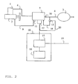
- shows an electrically controlled compressor system with a test device.
- The following described illustrative embodiments of the invention, with refinements, should be regarded only as examples and should by no means serve to limit the scope of protection of the patent claims. In the illustrative embodiments here described, the same reference numerals refer in the various figures to the same type of component.
- A traditional air dryer according to fig. 1 has a so-called off-line regeneration. The air which is pumped out from a compressor 1 deposits water droplets, which means that the
air dryer 7 is exposed to moisture. Following completion of the compression, theair dryer 7 has to be dried with dry air. The compressor 1, with incorporatedmotor 2, supplies compressed air to theair dryer 7 through a conduit 4. Theair dryer 7 is in turn coupled, by aconduit 5, to aseparate tank 8, constituting a regeneration tank containing dry air. Coupled to theair dryer 7 by aconduit 6, via anonreturn valve 10, is apressure tank 3. In this case, thepressure tank 3 represents the compressed-air-consuming system in the vehicle. When the pressure in thepressure tank 3 has reached a predefined maximum value, avalve 11 on the air dryer is opened in order thereby to reduce the pressure and terminate the pumping. Should the system also contain acontrol conduit 9 for relieving the compressor, this conduit, too, is activated. The air in theregeneration tank 8 is thereafter fed back through theair dryer 7 for drying of the drying mass in theair dryer 7. After this, it is possible to reuse theair dryer 7. Theair dryer 7 has apneumatic control unit 12 and the air dryer also often incorporates a pneumatic control signal which runs via thecontrol conduit 9 disposed between theair dryer 7 and the compressor 1. This pneumatic control signal enables the pumping of the compressor to be shut off, so that the pumping of air can be started and stopped in a controlled manner. - An electrically controlled air dryer has a so-called in-line regeneration according to fig. 2 for the purpose of drying the air, which means that a by-
pass coupling 14 is used instead of the regeneration tank used in a traditional air dryer. The by-pass coupling 14 is disposed either in theair dryer 7 or between thepressure tank 3 and theair dryer 7. In the by-pass coupling there is avalve 13, which can be opened and can let back air from the tank to the air dryer. Thevalve 13 is controlled via awire 20 from anelectric control unit 17, which is either an integral part of the air dryer or a separate control unit. Theair dryer 7 is dried by dry air being taken from thepressure tank 3, after which this dry air is fed back through theair dryer 7 to dry the drying mass in theair dryer 7 until the air dryer has become once again dry. - The method according to the invention can advantageously be used in an electrically controlled air dryer having a so-called in-line regeneration, since a special evacuation of air from the air tank is made on an already existing system. No extra equipment needs to be fitted on the vehicle in order to perform the capacity check on the compressor.
- The
test device 18 in fig. 2 is constituted by acontrol unit 15 coupled to theordinary control unit 17 of the air dryer. Thecontrol unit 15 comprises a processor, memory and suitable input and output circuits which are well known to the person skilled in the art. Thecontrol unit 15 is also connected to aninstrument panel 16 for displaying generated information concerning the compressor capacity. The compressor is driven by amotor 2 and the speed of the motor is set to a predefined value prior to the start of the test. The compressor pumps air until a predefined pressure P1 is achieved in thepressure tank 3, after which the compressor is relieved of load. When this value of P1 has been found to be stable, i.e. air is not leaking out from the system, a quantity of air is evacuated from thepressure tank 3. This is effected by avalve 13 being held open for a set period, in which the air is allowed to flow out. The air flows out through an opening (not shown) of predefined size. The pressure in the pressure tank is measured as the air is evacuated and, since the diameter of the opening is known, the discharge flow, and hence the evacuated quantity of air, can be calculated. The measurement of the pressure can take place continuously, i.e. analogously throughout the measurement or at regular or irregular intervals. When the evacuation of air has been completed, an instantaneous pressure P2 is registered by thecontrol unit 15. - The compressor then refills the
pressure tank 3 until the original pressure P1 has been achieved. Once the evacuated quantity of air has been calculated, the quantity of air pumped by the compressor when the pressure in the pressure tank was increased from the pressure P2 to the pressure P1 is known. Thecontrol unit 15 measures the time t1 consumed when the compressor increases the pressure from the pressure P2 in the pressure tank to the original pressure P1. The control unit then checks whether this time t1 lies within a predefined time range tr. The predefined time range tr is the time consumed when a compressor with acceptable capacity pumps the corresponding quantity of air. Values of tr for different compressor speeds can be stored in a database in thecontrol unit 15. If the time t1 lies outside the predefined time range tr, thecontrol unit 15 generates a error message indicating that the used compressor should be exchanged since its pump capacity is too low. This error message can be shown in aninstrument panel 16 forming part of the test device. - In one example, a compressor is fitted on a vehicle. Since the method presupposes that no air consumption occurs during execution of the method, the method is most advantageously carried out after the vehicle has been started and the compressed air system has reached a steady state. The compressor is driven by the engine of the vehicle, which has a preset speed of 1000 rpm. The pressure P1 is set to a level below the cut-off pressure of the system, for example 11.5 bar. A valve is thereafter held open for a certain period, whereupon the air is discharged through a predefined opening of known geometry. The air flow through the opening is calculated by continuously measuring the pressure in the pressure tank and the evacuated volume is subsequently calculated. This is done by applying a generally known correlation such as Bernoulli's equation. The pressure P1 in the tank is measured prior to the start of the test. Thereafter, the pressure is measured continuously as air is evacuated for a certain period, after which the evacuated quantity of air can be integrated on a forward basis. By letting the air flow out in this way, a method is obtained which is independent of the volume of the pressure tank and it is thus applicable to different types of vehicle and vehicle variants with variously large compressed air volumes. On certain vehicle variants superstructures can be fitted, which does not affect the measuring method.
- The principle of measuring how great a volume is discharged from the pressure tank is that the air, for a set period, is fed out from the pressure tank through an opening of specific geometry. If Bernoulli's equation is applied, then evacuated volume is obtained according to:


in which
V = evacuated volume (liters)
Φ = air flow (liters/s),
P = the air pressure (Pa) and
d = the diameter of the opening (dm) - The method can be initiated, for example, when the vehicle is ready for servicing in a workshop and is connected via a
connection 19 to a test apparatus in the workshop (not shown). The compressor capacity is thereafter reported to a service mechanic via the test apparatus. - Another way of initiating the method is for the initiation to take place in a menu system present in the vehicle. In this case, the result is shown in the
instrument panel 16. - Apart from the capacity check being simple to conduct, it is independent of the volume of the air reservoir and is therefore valid for vehicles of different types.
- For a twin-cylinder compressor with 700 cm3 cubic capacity, a reasonable value of t1 is, for example, 5 seconds, and tr can be 1.7*t1, i.e. a deterioration in pump capacity of around 40% for an approved compressor.
- In an alternative embodiment, the compressor is driven by a
motor 2 and the speed of the motor is set to a predefined value. The higher the chosen speed, the quicker the test can be performed. The compressor pumps air until a predefined pressure P1 is achieved in the pressure tank. When this value of P1 has been achieved, a quantity of air is evacuated from thepressure tank 3. This is done by evacuating air through a predefined opening until a second pressure P2 in the pressure tank has been achieved and has been registered by thecontrol unit 15. The time spent on getting the pressure to drop from the pressure P1 to the pressure P2 is used to calculate, with the aid of Bernoulli's equation, the volume of the evacuated quantity of air. The compressor pumps the pressure in thepressure tank 3 back up to the original pressure P1. Thecontrol unit 15 measures the time t1 consumed when the compressor increases the pressure from the pressure P2 in the pressure tank to the original pressure P1. The control unit then checks whether this time t1 lies within a predefined time range tr. If the time t1 lies outside the predefined time range tr, the control unit generates a error message. This error message can be shown in aninstrument panel 16 forming part of the test device. - Another refinement of the method includes a check that the first pressure (P1) in the
pressure tank 3 lies within a predefined pressure range for a certain set period. A leakage of air from the compressed air system or to other reservoirs can thereby be detected. Air leakage from thepressure tank 3 renders the capacity check ineffectual. - In another advantageous illustrative embodiment, the method can be applied to a compressor forming part of a free-standing air generation unit used, for example, at building sites.
- In another refinement, the monitoring can be remote-controlled via the internet or by telephone. This is particularly advantageous in respect of free-standing air generation units, which are often unmonitored. In this case, the test can be realized independently by the system. The compressor is in this case set to conduct the test at regular intervals, for example each time it is started. The system can call a monitoring center and send error messages and/or a report of the compressor capacity.
- Another advantage with the invention is that the capacity check can be realized automatically by an algorithm in the control system ensuring that the test is conducted at programmed regular intervals.
- The invention should not be considered to be limited to the illustrative embodiments described above, but rather a host of further variants and modifications are conceivable within the scope of the following patent claims. For example, the method is not only applicable to ground vehicles, but also to, for example, airplanes, boats, etc. For example, a flow meter in the predefined hole can be used, instead of calculating the flow from the pressure tank.
Claims (10)
- A method for evaluating the capacity of a compressor (1), comprising the following steps:- setting the speed of the compressor to a constant and predefined value,- with said compressor, filling a pressure tank (3) so that a first predefined pressure, P1, is achieved in the pressure tank (3) and subsequently relieving the compressor,- opening a valve (11) so that a quantity of air from the pressure tank (3) is allowed to flow out from an opening of predefined size,- measuring the pressure in the pressure tank (3) during the evacuation of the air,- shutting the valve (11) once said quantity of air has been evacuated,- registering instantaneous pressure, P2, in the pressure tank (3) once the valve (11) has been shut,- calculating the evacuated quantity of air,- with the compressor, filling the pressure tank (3) until the first pressure, P1, in the pressure tank (3) is registered again,- registering the time, t1, which is needed to raise the pressure in the pressure tank (3) from the pressure P2 to the pressure P1,- generating a error message if the time, t1, lies outside a predefined time range, tr.
- The method as claimed in patent claim 1, comprising the step of shutting the valve (11) after a specific time.
- The method as claimed in patent claim 1, comprising the step of shutting the valve (11) once a predefined pressure P2 has been measured in the pressure tank (3).
- The method as claimed in patent claims 1-3, comprising the step of checking that the pressure, P1, lies within a predefined pressure range, Pr, for a predefined time, tf, before said quantity of air is evacuated from the pressure tank (3).
- The method as claimed in claims 1-4, comprising the step of the method being carried out at predefined time intervals and/or each time the compressor is started.
- The method as claimed in claims 1-5, comprising the step of the method being initiated by a person using a menu system present in the vehicle.
- The method as claimed in patent claims 1-5, comprising the step of the method being initiated by an outer signal.
- A device for evaluating the capacity of an air compressor (1), comprising a pressure tank (3) having a valve (11) and an opening of known geometry, and a control unit (15), wherein said control unit (15) is designed to set the speed of the compressor (1) to a predefined value and open and shut the valve (11) so as to evacuate a certain quantity of air from the pressure tank (3) through the opening, after which the control unit (15), via the compressor (1), fills the pressure tank (3) with said quantity of air for a certain time, t1, and compares whether the time t1 lies within a predefined time range.
- The device as claimed in patent claim 8, characterized in that the device is connected to a compressor (1) forming part of a free-standing air generation unit.
- The device as claimed in patent claim 8, characterized in that the device is connected to a compressor fitted on a vehicle.
Applications Claiming Priority (3)
| Application Number | Priority Date | Filing Date | Title |
|---|---|---|---|
| SE0300777A SE524994C2 (en) | 2003-03-21 | 2003-03-21 | Method and apparatus for checking the capacity of a compressor |
| SE0300777 | 2003-03-21 | ||
| PCT/SE2004/000089 WO2004083801A1 (en) | 2003-03-21 | 2004-01-22 | Method and device for control of the capacity of a compressor |
Publications (2)
| Publication Number | Publication Date |
|---|---|
| EP1608946A1 EP1608946A1 (en) | 2005-12-28 |
| EP1608946B1 true EP1608946B1 (en) | 2007-03-28 |
Family
ID=20290738
Family Applications (1)
| Application Number | Title | Priority Date | Filing Date |
|---|---|---|---|
| EP04704376A Expired - Lifetime EP1608946B1 (en) | 2003-03-21 | 2004-01-22 | Method and device for control of the capacity of a compressor |
Country Status (7)
| Country | Link |
|---|---|
| US (1) | US7287423B2 (en) |
| EP (1) | EP1608946B1 (en) |
| AT (1) | ATE358272T1 (en) |
| BR (1) | BRPI0408596A (en) |
| DE (1) | DE602004005579T2 (en) |
| SE (1) | SE524994C2 (en) |
| WO (1) | WO2004083801A1 (en) |
Cited By (1)
| Publication number | Priority date | Publication date | Assignee | Title |
|---|---|---|---|---|
| CN102645373A (en) * | 2011-02-22 | 2012-08-22 | 上海德朗汽车零部件制造有限公司 | Computer test control system for pressure alternating test of air-air intercooler |
Families Citing this family (18)
| Publication number | Priority date | Publication date | Assignee | Title |
|---|---|---|---|---|
| CN1332133C (en) * | 2005-03-13 | 2007-08-15 | 周巽 | Method for deciding key characteristic of compressor qualified or not by timing exhaust volume |
| CN100419264C (en) * | 2005-03-13 | 2008-09-17 | 葛焕森 | Method for Determining Critical Compressor Characteristics by Elapsed Time Limiting Discharge Volume |
| DE102005019783A1 (en) * | 2005-04-28 | 2006-11-09 | Continental Aktiengesellschaft | Level control system for a motor vehicle |
| CN101672729B (en) * | 2009-10-14 | 2011-02-16 | 清华大学 | High-altitude and low-pressure characteristic simulation test station of air compressor in internal-combustion engine |
| DE102010024059A1 (en) * | 2010-06-17 | 2011-12-22 | Knorr-Bremse Systeme für Nutzfahrzeuge GmbH | Compressed air system for commercial vehicles, has compressor, low-pressure container for storing pressure air on pressure level, where high-pressure container is provided for storing pressure air on another pressure level |
| CN101984256B (en) * | 2010-11-16 | 2012-10-03 | 潍柴动力股份有限公司 | Load increasing and reducing device of air compressor |
| CN102645374B (en) * | 2011-02-22 | 2013-12-25 | 上海德朗汽车零部件制造有限公司 | Pressure alternating test system of air-air intercooler |
| CN102645337B (en) * | 2011-02-22 | 2014-10-15 | 上海理工技术转移有限公司 | Gas circulation system for pressure alternating test of gas-gas intercooler |
| CN102654469A (en) * | 2012-05-10 | 2012-09-05 | 沈阳仪表科学研究院 | Device for fire resistance tests of pressure elements |
| CN102749207B (en) * | 2012-07-11 | 2014-11-05 | 杭州沃镭科技有限公司 | Safe pressure test device for automobile-purposed air dryer |
| KR101532485B1 (en) * | 2013-09-17 | 2015-06-30 | 코리아에프티 주식회사 | Canister inspection equipment |
| CN106194698B (en) * | 2016-06-28 | 2018-09-14 | 上海高桥捷派克石化工程建设有限公司 | Compressor test run bench control system and control method |
| CN106197977B (en) * | 2016-07-06 | 2018-07-13 | 公安部天津消防研究所 | Gas extinguishing system high pressure, large-flow check valve action test device and method |
| CN106499651B (en) * | 2016-10-20 | 2017-11-28 | 北京理工大学 | A kind of centrifugal compressor Non-steady characteristics platform and test method |
| JP6851953B2 (en) * | 2017-10-30 | 2021-03-31 | アークレイ株式会社 | Pump drive method |
| CN108931277B (en) * | 2018-07-06 | 2020-06-19 | 西安工程大学 | Method for detecting total leakage of compressed air system of textile mill |
| CN113309692B (en) * | 2021-05-27 | 2023-02-03 | 广东电网有限责任公司 | A GIS equipment air pressure supply method, device, medium and electronic equipment |
| CN115683484A (en) * | 2022-10-10 | 2023-02-03 | 浙江氢途科技有限公司 | A new type of fuel cell gas tightness detection equipment and method |
Family Cites Families (7)
| Publication number | Priority date | Publication date | Assignee | Title |
|---|---|---|---|---|
| US2782637A (en) * | 1955-07-13 | 1957-02-26 | Gen Electric | Apparatus for testing compressors |
| US4052135A (en) * | 1976-05-11 | 1977-10-04 | Gardner-Denver Company | Control system for helical screw compressor |
| SE432465B (en) * | 1980-06-02 | 1984-04-02 | Sullair Tech Ab | VALVE ARRANGEMENTS FOR CAPACITY CONTROL OF SCREW COMPRESSORS |
| US4676095A (en) * | 1985-11-22 | 1987-06-30 | Columbia Gas System Service Corp. | Apparatus for measuring the work performed by a gas compressor |
| US5811669A (en) * | 1997-02-20 | 1998-09-22 | Rodolfo Esteban Polonyi | Cycling compressor performance metering |
| US6227815B1 (en) * | 1999-06-30 | 2001-05-08 | Campbell Hausfeld/Scott Fetzer Company | Pressure control for a reciprocating compressor |
| US7328587B2 (en) * | 2004-01-23 | 2008-02-12 | York International Corporation | Integrated adaptive capacity control for a steam turbine powered chiller unit |
-
2003
- 2003-03-21 SE SE0300777A patent/SE524994C2/en not_active IP Right Cessation
-
2004
- 2004-01-22 WO PCT/SE2004/000089 patent/WO2004083801A1/en not_active Ceased
- 2004-01-22 BR BRPI0408596-5A patent/BRPI0408596A/en not_active IP Right Cessation
- 2004-01-22 AT AT04704376T patent/ATE358272T1/en not_active IP Right Cessation
- 2004-01-22 DE DE602004005579T patent/DE602004005579T2/en not_active Expired - Lifetime
- 2004-01-22 EP EP04704376A patent/EP1608946B1/en not_active Expired - Lifetime
-
2006
- 2006-09-21 US US11/162,755 patent/US7287423B2/en not_active Expired - Fee Related
Cited By (1)
| Publication number | Priority date | Publication date | Assignee | Title |
|---|---|---|---|---|
| CN102645373A (en) * | 2011-02-22 | 2012-08-22 | 上海德朗汽车零部件制造有限公司 | Computer test control system for pressure alternating test of air-air intercooler |
Also Published As
| Publication number | Publication date |
|---|---|
| US7287423B2 (en) | 2007-10-30 |
| BRPI0408596A (en) | 2006-03-21 |
| WO2004083801A1 (en) | 2004-09-30 |
| ATE358272T1 (en) | 2007-04-15 |
| DE602004005579D1 (en) | 2007-05-10 |
| EP1608946A1 (en) | 2005-12-28 |
| SE0300777L (en) | 2004-09-22 |
| US20070012098A1 (en) | 2007-01-18 |
| SE524994C2 (en) | 2004-11-09 |
| SE0300777D0 (en) | 2003-03-21 |
| DE602004005579T2 (en) | 2007-12-06 |
Similar Documents
| Publication | Publication Date | Title |
|---|---|---|
| US7287423B2 (en) | Method and device for control of the capacity of a compressor | |
| US20060196250A1 (en) | Leakage tester | |
| CN110284953B (en) | Urea pump aging degree evaluation method and device | |
| CN114234038B (en) | Hydrogen management system and hydrogen cylinder valve state detection method thereof | |
| CN110678643B (en) | Maintenance system | |
| CN101253086A (en) | Method for determining initial pressure in a motor vehicle braking system | |
| JP2019167836A (en) | Abnormality diagnostic device and abnormality diagnostic method | |
| EP2999878A1 (en) | Method and device for functional control of a high pressure fuel pump | |
| WO2019181996A1 (en) | Error diagnosis device and error diagnosis method | |
| CN213022137U (en) | An air tightness detection system for hydrogen energy vehicles | |
| CN100354167C (en) | Braking controller and its fault diagnostic method | |
| CN116929639B (en) | A method for improving the efficiency of engine casing air tightness detection equipment | |
| CN214408457U (en) | High-pressure test device for pipeline rupture valve | |
| CN111152944A (en) | Surface tension storage tank bubble breaking point testing method and system | |
| JPH07133894A (en) | How to fill natural gas | |
| CN110594067A (en) | Fuel injector diagnostic systems and methods | |
| CN115503673A (en) | A processing method, device, equipment and storage medium for vehicle brake softness | |
| CN104180877B (en) | A kind of fuel sensor and combination instrument match test platform | |
| CN119712515B (en) | Electric air compressor control method, device, equipment and readable storage medium | |
| CN113795663A (en) | Method and direct water injection system for determining air quality | |
| CN222719932U (en) | Sensitivity detection device for gas alarm | |
| CN110926846A (en) | A water test device for fire terminal | |
| CN221664868U (en) | A high-pressure multi-stage compressor core installation and positioning structure and a vehicle-mounted air pump | |
| CN114062145B (en) | A water pipe testing device and water pipe detection system in a mold | |
| CN221664863U (en) | Multifunctional vehicle-mounted inflator pump with double-motor type high-low pressure inflator assembly |
Legal Events
| Date | Code | Title | Description |
|---|---|---|---|
| PUAI | Public reference made under article 153(3) epc to a published international application that has entered the european phase |
Free format text: ORIGINAL CODE: 0009012 |
|
| 17P | Request for examination filed |
Effective date: 20051021 |
|
| AK | Designated contracting states |
Kind code of ref document: A1 Designated state(s): AT BE BG CH CY CZ DE DK EE ES FI FR GB GR HU IE IT LI LU MC NL PT RO SE SI SK TR |
|
| AX | Request for extension of the european patent |
Extension state: AL LT LV MK |
|
| DAX | Request for extension of the european patent (deleted) | ||
| GRAP | Despatch of communication of intention to grant a patent |
Free format text: ORIGINAL CODE: EPIDOSNIGR1 |
|
| GRAS | Grant fee paid |
Free format text: ORIGINAL CODE: EPIDOSNIGR3 |
|
| GRAA | (expected) grant |
Free format text: ORIGINAL CODE: 0009210 |
|
| AK | Designated contracting states |
Kind code of ref document: B1 Designated state(s): AT BE BG CH CY CZ DE DK EE ES FI FR GB GR HU IE IT LI LU MC NL PT RO SE SI SK TR |
|
| PG25 | Lapsed in a contracting state [announced via postgrant information from national office to epo] |
Ref country code: FI Free format text: LAPSE BECAUSE OF FAILURE TO SUBMIT A TRANSLATION OF THE DESCRIPTION OR TO PAY THE FEE WITHIN THE PRESCRIBED TIME-LIMIT Effective date: 20070328 Ref country code: CH Free format text: LAPSE BECAUSE OF FAILURE TO SUBMIT A TRANSLATION OF THE DESCRIPTION OR TO PAY THE FEE WITHIN THE PRESCRIBED TIME-LIMIT Effective date: 20070328 Ref country code: LI Free format text: LAPSE BECAUSE OF FAILURE TO SUBMIT A TRANSLATION OF THE DESCRIPTION OR TO PAY THE FEE WITHIN THE PRESCRIBED TIME-LIMIT Effective date: 20070328 Ref country code: SI Free format text: LAPSE BECAUSE OF FAILURE TO SUBMIT A TRANSLATION OF THE DESCRIPTION OR TO PAY THE FEE WITHIN THE PRESCRIBED TIME-LIMIT Effective date: 20070328 Ref country code: BE Free format text: LAPSE BECAUSE OF FAILURE TO SUBMIT A TRANSLATION OF THE DESCRIPTION OR TO PAY THE FEE WITHIN THE PRESCRIBED TIME-LIMIT Effective date: 20070328 Ref country code: AT Free format text: LAPSE BECAUSE OF FAILURE TO SUBMIT A TRANSLATION OF THE DESCRIPTION OR TO PAY THE FEE WITHIN THE PRESCRIBED TIME-LIMIT Effective date: 20070328 |
|
| REG | Reference to a national code |
Ref country code: GB Ref legal event code: FG4D |
|
| REG | Reference to a national code |
Ref country code: CH Ref legal event code: EP |
|
| REF | Corresponds to: |
Ref document number: 602004005579 Country of ref document: DE Date of ref document: 20070510 Kind code of ref document: P |
|
| REG | Reference to a national code |
Ref country code: IE Ref legal event code: FG4D |
|
| PG25 | Lapsed in a contracting state [announced via postgrant information from national office to epo] |
Ref country code: ES Free format text: LAPSE BECAUSE OF FAILURE TO SUBMIT A TRANSLATION OF THE DESCRIPTION OR TO PAY THE FEE WITHIN THE PRESCRIBED TIME-LIMIT Effective date: 20070709 |
|
| REG | Reference to a national code |
Ref country code: SE Ref legal event code: TRGR |
|
| PG25 | Lapsed in a contracting state [announced via postgrant information from national office to epo] |
Ref country code: PT Free format text: LAPSE BECAUSE OF FAILURE TO SUBMIT A TRANSLATION OF THE DESCRIPTION OR TO PAY THE FEE WITHIN THE PRESCRIBED TIME-LIMIT Effective date: 20070828 |
|
| ET | Fr: translation filed | ||
| REG | Reference to a national code |
Ref country code: CH Ref legal event code: PL |
|
| PG25 | Lapsed in a contracting state [announced via postgrant information from national office to epo] |
Ref country code: SK Free format text: LAPSE BECAUSE OF FAILURE TO SUBMIT A TRANSLATION OF THE DESCRIPTION OR TO PAY THE FEE WITHIN THE PRESCRIBED TIME-LIMIT Effective date: 20070328 |
|
| PG25 | Lapsed in a contracting state [announced via postgrant information from national office to epo] |
Ref country code: RO Free format text: LAPSE BECAUSE OF FAILURE TO SUBMIT A TRANSLATION OF THE DESCRIPTION OR TO PAY THE FEE WITHIN THE PRESCRIBED TIME-LIMIT Effective date: 20070328 Ref country code: CZ Free format text: LAPSE BECAUSE OF FAILURE TO SUBMIT A TRANSLATION OF THE DESCRIPTION OR TO PAY THE FEE WITHIN THE PRESCRIBED TIME-LIMIT Effective date: 20070328 |
|
| PG25 | Lapsed in a contracting state [announced via postgrant information from national office to epo] |
Ref country code: DK Free format text: LAPSE BECAUSE OF FAILURE TO SUBMIT A TRANSLATION OF THE DESCRIPTION OR TO PAY THE FEE WITHIN THE PRESCRIBED TIME-LIMIT Effective date: 20070328 |
|
| PLBE | No opposition filed within time limit |
Free format text: ORIGINAL CODE: 0009261 |
|
| STAA | Information on the status of an ep patent application or granted ep patent |
Free format text: STATUS: NO OPPOSITION FILED WITHIN TIME LIMIT |
|
| 26N | No opposition filed |
Effective date: 20080102 |
|
| PG25 | Lapsed in a contracting state [announced via postgrant information from national office to epo] |
Ref country code: GR Free format text: LAPSE BECAUSE OF FAILURE TO SUBMIT A TRANSLATION OF THE DESCRIPTION OR TO PAY THE FEE WITHIN THE PRESCRIBED TIME-LIMIT Effective date: 20070629 |
|
| PG25 | Lapsed in a contracting state [announced via postgrant information from national office to epo] |
Ref country code: MC Free format text: LAPSE BECAUSE OF NON-PAYMENT OF DUE FEES Effective date: 20080131 |
|
| PG25 | Lapsed in a contracting state [announced via postgrant information from national office to epo] |
Ref country code: IE Free format text: LAPSE BECAUSE OF NON-PAYMENT OF DUE FEES Effective date: 20080122 Ref country code: EE Free format text: LAPSE BECAUSE OF FAILURE TO SUBMIT A TRANSLATION OF THE DESCRIPTION OR TO PAY THE FEE WITHIN THE PRESCRIBED TIME-LIMIT Effective date: 20070328 |
|
| PG25 | Lapsed in a contracting state [announced via postgrant information from national office to epo] |
Ref country code: CY Free format text: LAPSE BECAUSE OF FAILURE TO SUBMIT A TRANSLATION OF THE DESCRIPTION OR TO PAY THE FEE WITHIN THE PRESCRIBED TIME-LIMIT Effective date: 20070328 |
|
| PG25 | Lapsed in a contracting state [announced via postgrant information from national office to epo] |
Ref country code: BG Free format text: LAPSE BECAUSE OF FAILURE TO SUBMIT A TRANSLATION OF THE DESCRIPTION OR TO PAY THE FEE WITHIN THE PRESCRIBED TIME-LIMIT Effective date: 20070628 |
|
| PG25 | Lapsed in a contracting state [announced via postgrant information from national office to epo] |
Ref country code: HU Free format text: LAPSE BECAUSE OF FAILURE TO SUBMIT A TRANSLATION OF THE DESCRIPTION OR TO PAY THE FEE WITHIN THE PRESCRIBED TIME-LIMIT Effective date: 20070929 Ref country code: LU Free format text: LAPSE BECAUSE OF NON-PAYMENT OF DUE FEES Effective date: 20080122 |
|
| PG25 | Lapsed in a contracting state [announced via postgrant information from national office to epo] |
Ref country code: TR Free format text: LAPSE BECAUSE OF FAILURE TO SUBMIT A TRANSLATION OF THE DESCRIPTION OR TO PAY THE FEE WITHIN THE PRESCRIBED TIME-LIMIT Effective date: 20070328 |
|
| PGFP | Annual fee paid to national office [announced via postgrant information from national office to epo] |
Ref country code: DE Payment date: 20120118 Year of fee payment: 9 |
|
| PGFP | Annual fee paid to national office [announced via postgrant information from national office to epo] |
Ref country code: GB Payment date: 20120118 Year of fee payment: 9 Ref country code: SE Payment date: 20120112 Year of fee payment: 9 Ref country code: IT Payment date: 20120114 Year of fee payment: 9 |
|
| PGFP | Annual fee paid to national office [announced via postgrant information from national office to epo] |
Ref country code: NL Payment date: 20120117 Year of fee payment: 9 |
|
| PGFP | Annual fee paid to national office [announced via postgrant information from national office to epo] |
Ref country code: FR Payment date: 20130204 Year of fee payment: 10 |
|
| REG | Reference to a national code |
Ref country code: NL Ref legal event code: V1 Effective date: 20130801 |
|
| REG | Reference to a national code |
Ref country code: SE Ref legal event code: EUG |
|
| GBPC | Gb: european patent ceased through non-payment of renewal fee |
Effective date: 20130122 |
|
| PG25 | Lapsed in a contracting state [announced via postgrant information from national office to epo] |
Ref country code: NL Free format text: LAPSE BECAUSE OF NON-PAYMENT OF DUE FEES Effective date: 20130801 Ref country code: SE Free format text: LAPSE BECAUSE OF NON-PAYMENT OF DUE FEES Effective date: 20130123 Ref country code: DE Free format text: LAPSE BECAUSE OF NON-PAYMENT OF DUE FEES Effective date: 20130801 |
|
| REG | Reference to a national code |
Ref country code: DE Ref legal event code: R119 Ref document number: 602004005579 Country of ref document: DE Effective date: 20130801 |
|
| PG25 | Lapsed in a contracting state [announced via postgrant information from national office to epo] |
Ref country code: GB Free format text: LAPSE BECAUSE OF NON-PAYMENT OF DUE FEES Effective date: 20130122 |
|
| REG | Reference to a national code |
Ref country code: FR Ref legal event code: ST Effective date: 20140930 |
|
| PG25 | Lapsed in a contracting state [announced via postgrant information from national office to epo] |
Ref country code: FR Free format text: LAPSE BECAUSE OF NON-PAYMENT OF DUE FEES Effective date: 20140131 |
|
| PG25 | Lapsed in a contracting state [announced via postgrant information from national office to epo] |
Ref country code: IT Free format text: LAPSE BECAUSE OF NON-PAYMENT OF DUE FEES Effective date: 20140122 |