TECHNICAL FIELD
The present invention relates to a wireless ad hoc
communication system, and particularly relates to a wireless ad
hoc communication system, a terminal in this system, and a
processing method therein as well as a program to make a
computer (terminal) execute this method, wherein an alternative
route is discovered in order to prepare for a route switching
thereafter during transmission of a packet when the intermediate
link quality deteriorates.
BACKGROUND ART
Since a miniaturization and performance enhancement of an
electronic device has advanced and it becomes possible to carry
and use easily the electronic device, there is a requirement for
an environment that makes communication possible by connecting a
terminal to a network at a place where a necessity occurs. As
one of such environments, a development of a network that is
temporarily established whenever necessary, specifically
wireless ad hoc network technology, has been progressed. In this
wireless ad hoc network, a specific access point is not provided
and each terminal (for example, computer, handheld information
terminal (PDA: Personal Digital Assistance), mobile phone unit,
and the like) is autonomously distributed and mutually connected.
In this wireless ad hoc network, since a change in topology
frequently occurs differently from a conventional fixed network,
it is necessary to establish a route control method for securing
reliability, specifically a routing protocol. The routing
protocol of the wireless ad hoc network which has been proposed
presently is roughly classified into two categories that are an
on-demand method and a table drive method. In addition, a hybrid
method integrating these two methods has also been proposed.
The table drive method and the hybrid method are said to be
comparatively failure-resistant since route information is
always exchanged. On the other hand, a size of an overhead due
to constant transmission and reception of the information
becomes a problem. For example, it is inconvenient to always
exchange the route information from a view point of power
consumption when considering an environment in which a mobile
device driven by a battery is connected to a wireless ad hoc
network. In addition, there is also such a problem that it is
not possible to cope with a sudden failure when a cycle of
updating a route table is long.
On the other hand, in case of the on-demand method, a route
is formed by transmitting a route discovery request immediately
before starting communication, and therefore even when a failure
suddenly occurs in a link at a stage where the communication
starts, a valid route is formed disregarding that link. However,
when the quality of the link being used deteriorates during the
communication such that the route becomes not usable, the
communication is immediately interrupted and it is necessary to
form a route from a transmission source once again.
As a typical routing protocol of the on-demand method,
there is an AODV (Ad hoc On-demand Distance Vector) protocol
which is proposed by the MANET WG (Mobile Ad hoc NETwork Working
Group) of IETF (Internet Engineering Task Force), for example.
In this AODV protocol, a method has been proposed in which a
message requesting a rediscovery of a route is transmitted from
nodes at both ends and a route is newly formed by a method
called "local repair" when a failure occurs in a link to result
in break (for example, refer to Non-patent reference 1).
[Non-patent reference 1]
"Ad hoc ON-demand Distance Vector Routing", Charles E.
Perkins, et al., (USA), IETF, February 17, 2003, pp. 23-25,
Internet drafts <http://www.ietf.org/internet-drafts/draft-ietf-manet-aodv-13.txt>
DISCLOSURE OF THE INVENTION
According to the above-described prior art, a route to
which a failure occurs can be repaired by discovering an
alternative route, but when such repair is not possible, either
of nodes having a link in which the failure occurs as the route
transmits a route error message to a transmission source. A node
that has received the route error message transfers the route
error message further to the transmission source after deleting
the corresponding route.
Due to such nature, when a failure occurs in one link and a
repair is not possible, all routes are to be deleted while
repeating the transfer of the route error message. For example,
in such an ad hoc network that has 10 hops from a transmission
source to a reception destination, when a failure occurs in the
last one hop and a repair is not possible, all routes are to be
erased. Making up a route again from the beginning not only
incurs calculation costs but also requires time costs and incurs
packet loss.
Particularly, in a wireless ad hoc network, since a change
in topology occurs frequently due to a movement of a terminal
(node), a radio wave condition or the like, it is important to
secure a method capable of communication even at the time of a
break of a link. In the above-described prior art, when a
failure occurs in a link, it is tried to discover an alternative
route from a node where the failure is discovered, however, it
is necessary to erase all routes when that node once fails to
discover an alternative route. On the other hand, the
calculation costs and time costs become considerably high in a
method of discovering a route once again from a transmission
source. Particularly, in a large scale ad hoc network, since it
is too costly to erase all routes and to perform a route
discovery all over again from a transmission source even when a
failure occurs in one link close to a reception destination,
this method is not desirable in an environment of a power saving
orientation where a mobile device is assumed as a node.
Moreover, in the above-described prior art, the rediscovery
of the route is performed after the failure occurs in the link
to result in a break. Therefore, there is a possibility that a
smooth switching to a newly discovered route is not possible
since it takes time to rediscover a route after the break of the
link. Due to this reason, the method of the prior art is
considered not suitable to a situation where instantaneousness
is required, such as a case of a real-time distribution of a
moving image and voice, for example.
Particularly, in the wireless ad hoc network, it is
important to secure a method capable of communication even at
the time of a break of a link since a change in topology occurs
frequently due to a movement of a terminal (node), a radio wave
condition, and the like. Typically, a break of a link does not
occur suddenly, but there are many cases where the link quality
gradually deteriorates to be an eventual break. With an
alternative route being discovered in advance during a process
of such gradual deterioration, it is possible to cope with a
failure instantaneously, and consequentially it is expected to
improve the reliability.
Accordingly, the present invention is to attempt a repair
in an intermediate node without deleting all routes up to a
transmission source when an alternative route can not be
discovered in a certain node in a wireless ad hoc communication
system.
Further, the present invention is to obtain a prompt route
switching with an alternative route being discovered in advance
in order to prepare for a situation where the quality of a link
is deteriorated to result in break during communication in the
wireless ad hoc communication system.
In order to solve the problems described above, a wireless
ad hoc communication system according to the present invention
is formed of a plurality of terminals, including: a first
intermediate terminal which transmits an alternative route
discovery request when the quality of a link connected thereto
deteriorates between a source terminal that transmits
communication data and a destination terminal that receives this
communication data; and a second terminal which is positioned
upstream with respect to the first intermediate terminal between
the source terminal and the destination terminal and which
transmits data to the first intermediate terminal, wherein the
first intermediate terminal transmits a route error notification
to the second terminal when the request fails, and the second
intermediate terminal transmits an another-alternative-route
discovery request when the notification is received from the
first intermediate terminal. Accordingly, the second
intermediate terminal attempts restoration without deleting all
routes up to a transmission source when the alternative route
can not be discovered in the first intermediate terminal.
Further, the terminal of the present invention includes: a
route table in which a destination address of communication, the
next transfer destination address to reach the destination
address, a link state of a link connecting to the transfer
destination address, and an address list of a transmission
source that transmits the communication directed to the
destination address to this terminal are made to correspond and
are retained as a route entry; means for monitoring a state of
the link and for updating the link state; means for transmitting
to another terminal an alternative route discovery request with
respect to the corresponding destination address, when the
above-described link state becomes a stretched state; and means
for transmitting a route error notification to the transmission
source shown in the address list when the request fails.
Accordingly, the alternative route is searched when the link on
the route becomes the stretched state, and the alternative route
is searched further in a terminal of an upper stream than this
terminal by transmitting the route error notification when the
search fails.
Further, the terminal of the present invention includes: a
route table in which a destination address of communication, the
next transfer destination address to reach the destination
address, a link state of a link connecting to the transfer
destination address, and an address list of a transmission
source that transmits the communication directed to the
destination address to this terminal are made to correspond and
are retained as a route entry; means for monitoring a state of
the link and for updating the link state; and means for
transmitting route information on the link to the transmission
source shown in the address list when the link state becomes a
stretched state. Accordingly, transmission data is retained in a
data buffer in a terminal of an upper stream than this terminal
in preparation for a route switching thereafter by notifying the
route information.
Further, the terminal of the present invention includes a
data buffer and means for retaining data being transmitted to
another terminal in the data buffer when route information on a
link whose link state becomes a stretched state is received from
the above-described another terminal during transmission of the
data to the another terminal. Accordingly, the transmission data
retained in the data buffer in preparation for a route switching
thereafter when receiving the notification of the route
information.
Further, a processing method of the present invention is a
processing method in a terminal provided with a route table in
which a destination address of communication, the next transfer
destination address to reach the destination address, a link
state of a link connecting to the transfer destination address,
and an address list of a transmission source that transmits the
communication directed to the destination address to this
terminal are made to correspond and are retained as a route
entry, including the steps of: monitoring a state of the link
and updating the link state; transmitting route information on
the link to the transmission source shown in the address list
when the link state becomes a stretched state; transmitting to
another terminal an alternative route discovery request with
respect to the corresponding destination address, when the link
state becomes a stretched state; and transmitting a route error
notification to the transmission source shown in the address
list when the request fails. Accordingly, when the link on the
route becomes the stretched state, the link state is notified
and the transmission data is retained in the data buffer in
preparation for a route switching, and at the same time the
alternative route is searched and then the discovery of the
alternative route is urged in a terminal of an upper stream than
this terminal by transmitting the route error notification when
the search fails.
Further, the processing method of the present invention is
a processing method in a terminal provided with a data buffer,
including the steps of: retaining data being transmitted to
another terminal in the data buffer when route information on a
link whose link state becomes a stretched state is received from
another terminal during the transmission of the data to another
terminal; transmitting an alternative route discovery request
for the destination address to further another terminal when a
route error notification is received from another terminal
within a predetermined time after receiving the route
information; and discarding the data retained in the buffer when
the route error notification is not received from another
terminal even when the predetermined time passes after receiving
the route information. Accordingly, the discovery of the
alternative route is urged in a terminal of an upper stream than
this terminal by transmitting the route error notification when
the search for the alternative route fails, and the data that
becomes unnecessary is discarded from the data buffer when the
search for the alternative route is presumed to be successful.
Further, the processing method of the present invention is
a processing method in a terminal provided with: a route table
in which a destination address of communication, the next
transfer destination address to reach the destination address, a
link state of a link connecting to that transfer destination
address, and an address list of a transmission source that
transmits the communication directed to the destination address
to this terminal are made to correspond and are retained as a
route entry, and a data buffer, including the steps of:
retaining data being transmitted to another terminal in the data
buffer when a route information on a link whose link state
becomes a stretched state is received from another terminal
during the transmission of the data to another terminal;
transmitting an alternative route discovery request with respect
to the destination address to further another terminal when a
route error notification is received from another terminal
within predetermined time after receiving the route information;
transmitting a command to switch to this discovered alternative
route as a qualified route when the alternative route is
discovered with respect to the request; and transferring the
route error notification from another terminal to the
transmission source shown in the address list when the
alternative route is not discovered with respect to the request.
Accordingly, the alternative route is searched when the route
can not be discovered in a lower stream terminal than this
terminal, this discovered alternative route is switched as a
qualified route when the alternative route is discovered, and
the route error notification is transferred to a terminal of an
upper stream than this terminal in order to urge the discovery
of the alternative route when the alternative route can not be
discovered.
Further, a program of the present invention is a program to
make a terminal provided with a route table in which a
destination address of communication, the next transfer
destination address to reach the destination address, a link
state of a link connecting to the transfer destination address,
and an address list of a transmission source that transmits the
communication directed to the destination address to this
terminal are made to correspond and are retained as a route
entry, execute the procedures of: monitoring a state of the link
and updating the link state; transmitting route information on
the link to the transmission source shown in the address list
when the link state becomes a stretched state; transmitting an
alternative route discovery request with respect to the
corresponding destination address to further another terminal,
when the link state become the stretched state; and transmitting
a route error notification to the transmission source shown in
the above-described address list when the request fails.
Accordingly, the link state is notified to make the transmission
data retained in the data buffer in preparation for a route
switching and at the same time the alternative route is searched
when the link on the route becomes the stretched state, and then
the discovery of the alternative route is urged in a terminal of
an upper stream than this terminal by transmitting the route
error notification when the search fails.
Further, the program of the present invention is a program
to make a terminal provided with a data buffer execute the
procedures of: retaining data being transmitted to another
terminal in the data buffer when route information on a link
whose link state becomes a stretched state is received from
another terminal during the transmission of the data to another
terminal; transmitting an alternative route discovery request
with respect to the above-described destination address to
further another terminal when the route error notification is
received from another terminal within predetermined time after
receiving the route information; discarding the data retained in
the data buffer when the route error notification is not
received from another terminal even when the predetermined time
passes after receiving the route information. Accordingly, the
discovery of the alternative route is urged in a terminal of an
upper stream than this terminal by transmitting the route error
notification when the search with respect to the alternative
route fails, and the data that becomes unnecessary is discarded
from the data buffer when the search for the alternative route
is presumed to be successful.
Further, the program of the present invention is a program
to make a terminal provided with a route table in which a
destination address of communication, the next transfer
destination address to reach the destination address, a link
state of a link connecting to the transfer destination address,
and an address list of a transmission source that transmits the
communication directed to the destination address to this
terminal are made to correspond and are retained as a route
entry, and a data buffer, execute procedures of: retaining data
being transmitted to another terminal in the data buffer when
route information on a link whose link state becomes a stretched
state is received from the another terminal during the
transmission of the data to the another terminal; transmitting
an alternative route discovery request for the destination
address to further another terminal when a route error
notification is received from another terminal within
predetermined time after receiving the route information;
transmitting a command to switch to this discovered alternative
route as a qualified route when the alternative route is
discovered with respect to the request; and transferring the
route error notification from another terminal to the
transmission source shown in the address list when the
alternative route is not discovered with respect to the above-described
request. Accordingly, the alternative route is
searched when the route can not be discovered in a terminal of a
lower stream than this terminal, this discovered alternative
route is switched as the qualified route when the alternative
route is discovered, and the discovery of the alternative route
is urged by transferring the route error notification to a
terminal of an upper stream than this terminal when the
alternative route can not be discovered.
In order to solve the above-described problems, a wireless
ad hoc communication system of the present invention is formed
of a plurality of terminals and includes: a first intermediate
terminal that transmits an alternative route discovery request
when the quality of a link connected to this terminal
deteriorates between a source terminal that transmits
communication data and a destination terminal that receives the
communication data, and a second intermediate terminal that
sets a possible alternative route when the request is received,
wherein the first intermediate terminal transmits a command to
switch the route after the possible alternative route is set,
and the second intermediate terminal switches to the possible
alternative route as a qualified route when the command is
received. Accordingly, the possible alternative route is set
from the destination terminal to the source terminal and the
route switching is obtained promptly by using the quality
deterioration of the link as a trigger.
Further, the wireless ad hoc communication system of the
present invention is formed of a plurality of terminals and
includes: a source terminal that transmits communication data, a
destination terminal that receives the communication data, a
first intermediate terminal that transmits an alternative route
discovery request when the quality of a link connected to this
terminal deteriorates during transfer of the communication data
between the source terminal and the destination terminal, and a
second intermediate terminal that sets a possible alternative
route to the transmission terminal when the request is received
and transfers this request to further another terminal, wherein
the destination terminal transmits a reply to the request when
the request is received, the second intermediate terminal sets
the possible alternative route to the destination terminal when
the reply is received and transfers this reply to further
another terminal, the first intermediate terminal transmits a
first command to switch the route after the reply is received,
the second terminal switches to the possible alternative route
to the destination terminal as a qualified route when the first
command is received and transfers this first command to further
another terminal, the destination terminal transmits a second
command to switch when the first command is received, and the
second intermediate terminal switches to the possible
alternative route to the source terminal as the qualified route
when the second command is received and transfers the second
command to further another terminal. Accordingly, the possible
bidirectional alternative route is set between the source
terminal and the destination terminal and the route switching is
obtained promptly by using the quality deterioration of the link
as a trigger.
Further, a terminal of the present invention includes: a
route table in which a destination address of communication, the
next transfer destination address to reach the destination
address, and a link state of a link connecting to the transfer
destination address are made to correspond and are retained as a
route entry; means for monitoring a state of the link and for
updating the link state; and means for transmitting to another
terminal an alternative route discovery request with respect to
the corresponding destination address, when the link state
becomes a stretched state. Accordingly, the possible alternative
route is set and the route switching thereafter is obtained
promptly by using the quality deterioration of the link as a
trigger.
Further, the terminal of the present invention includes: a
route table in which a destination address of communication, the
next transfer destination address to reach the destination
address, and a link state of a link connecting to the transfer
destination address are made to correspond and are retained as a
route entry; means for receiving an alternative route discovery
request from another terminal; and means for setting a link
state of an alternative route to a source address in the request
as a candidate state into the above-described route table.
Accordingly, the possible alternative route is set to the
transmission source of the alternative route discovery request.
Further, the terminal of the present invention includes: a
route table in which a destination address of communication, the
next transfer destination address to reach the destination
address, and a link state of a link connecting to the transfer
destination address are made to correspond and are retained as a
route entry; means for receiving from another terminal a command
to switch to an alternative route; and means for setting an
route, whose link state is a candidate state, to the destination
address in the command as a valid state into the route table.
Accordingly, switching to the possible alternative route set in
advance as a qualified route is promptly performed.
Further, a processing method of the present invention is a
processing method in a terminal provided with a route table in
which a destination address of communication, the next transfer
destination address to reach the destination address, and a link
state of a link connecting to the transfer destination address
are made to correspond and are retained as a route entry,
including the steps of: monitoring a state of the link and
updating the link state; transmitting to another terminal an
alternative route discovery request with respect to the
corresponding destination address, when the link state becomes a
stretched state; and transmitting a command to switch to the
discovered alternative route as a qualified route. Accordingly,
the possible alternative route is set and the route switching is
obtained promptly by using the quality deterioration of the link
as a trigger.
Further, the processing method of the present invention is
a processing method in a terminal provided with a route table in
which a destination address of communication, the next transfer
destination address to reach the destination address, and a link
state of a link connecting to the transfer destination address
are made to correspond and are retained as a route entry,
including the steps of: receiving an alternative route discovery
request from another terminal; setting a link state of an
alternative route to a source address in the request as a
candidate state into the route table; transmitting a reply to
this request when the destination address in the request is an
address of this terminal and transferring this request to
another terminal when the destination address in the request is
not the address thereof. Accordingly, the possible alternative
route to the transmission source of the alternative route
discovery request is set.
Further, the processing method of the present invention is
a processing method in a terminal provided with a route table in
which a destination address of communication, the next transfer
destination address to reach the destination address, and a link
state of a link connecting to the transfer destination address
are made to correspond and are retained as a route entry,
including the steps of: receiving a command to switch to an
alternative route from another terminal; setting a route to the
destination address in the command as an invalid state into the
route table when there is a route whose link state is a
stretched state or a valid state; and setting the route, whose
link state is a candidate state, to the destination address in
the command as the valid state into the route table. Accordingly,
switching to the possible alternative route set in advance as a
qualified route is performed promptly.
Further, the program of the present invention is a program
to make a terminal provided with a route table in which a
destination address of communication, the next transfer
destination address to reach the destination address, and a link
state of a link connecting to the transfer destination address
are made to correspond and are retained as a route entry execute
the procedures of: monitoring a state of the link and updating
the link state; transmitting to another terminal an alternative
route discovery request with respect to the corresponding
destination address, when the link state becomes a stretched
state; and transmitting a command to switch to the discovered
alternative route as a qualified route. Accordingly, the
possible alternative route is set and the route switching is
obtained promptly by using the quality deterioration of the link
as a trigger.
Further, the program of the present invention is a program
to make a terminal provided with a route table in which a
destination address of communication, the next transfer
destination address to reach the destination address, and a link
state of a link connecting to the transfer destination address
are made to correspond and are retained as a route entry execute
the procedures of: receiving an alternative route discovery
request from another terminal; setting a link state of an
alternative route to a source address in the request as a
candidate state into the route table; and transmitting a reply
to the request when the destination address in the request is
the address of this terminal and transferring the request to
another terminal when the destination address in the request is
not the address thereof. Accordingly, the possible alternative
route to the transmission source of the alternative route
discovery request is set.
Furthermore, the program of the present invention is a
program to make a terminal proved with a route table in which a
destination address of communication, the next transfer
destination address to reach the destination address, and a link
state of a link connecting to the transfer destination address
are made to correspond and are retained as a route entry execute
the procedures of: receiving a command to switch to an
alternative route from another terminal; setting a route to the
destination address in the command as an invalid state into the
table when there is a route whose link state is a stretched
state or a valid state; and setting the route, whose link state
is a candidate state, to the destination address in the command
as a valid state into the route table. Accordingly, switching to
the possible alternative route set in advance as a qualified
route is promptly performed.
BRIEF DESCRIPTION OF DRAWINGS
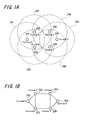
FIGS. 1A and 1B are diagrams showing an example of a
wireless ad hoc network that is assumed in a wireless ad hoc
communication system according to an embodiment of the present
invention;
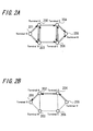
FIGS. 2A and 2B are diagrams showing a procedure for
setting a route in the wireless ad hoc network according to the
example of FIG. 1;
FIG. 3 is a diagram showing an outline of processing in
the embodiment of the present invention;
FIG. 4 is a diagram showing an configuration example of a
wireless terminal 100 in the embodiment of the present
invention;
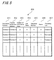
FIG. 5 is a diagram showing a configuration example of a
route table 610 retained in the wireless terminal 100 in the
embodiment of the present invention;
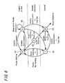
FIG. 6 is a diagram showing an example of a state
transition in a link state management process 40 according to
the embodiment of the present invention;
FIG. 7 is a diagram showing a configuration example of a
route information notification packet 830 that is used in a
route information notification process 50 according to the
embodiment of the present invention;
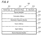
FIG. 8 is a diagram showing a configuration example of a
route request packet 810 that is used in an alternative route
search process 60 according to the embodiment of the present
invention;
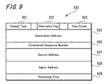
FIG. 9 is a diagram showing a configuration example of a
route reply packet 820 that is used in the alternative route
search process 60 according to the embodiment of the present
invention;
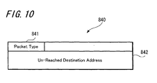
FIG. 10 is a diagram showing a configuration example of a
route error packet 840 that is used in the alternative route
search process 60 according to the embodiment of the present
invention;
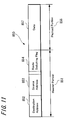
FIG. 11 is a diagram showing a configuration example of a
route switching packet 850 that is used in a route switching
process 70 according to the embodiment of the present invention;
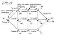
FIG. 12 is a diagram showing a route when a terminal C
transmits a route information notification in the embodiment of
the present invention;
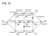
FIG. 13 is a diagram showing a route when the terminal C
transmits a route error in the embodiment of the present
invention;
FIG. 14 is a diagram showing a state in which a route is
switched to an alternative route between a terminal S and a
terminal D in the embodiment of the present invention;
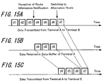
FIG. 15 is a diagram showing data transmission timing of a
terminal A before and after the route information notification
in the embodiment of the present invention;
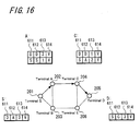
FIG. 16 is a diagram showing a route when communication is
performed from the terminal S toward the terminal D and contents
of a route table 610 in each terminal;
FIG. 17 is a diagram showing a route when the terminal A
requests an alternative route and the contents of the route
table 610 in each terminal;
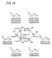
FIG. 18 is a diagram showing a route when a terminal B
transfers the request of the alternative route and the contents
of the route table 610 in each terminal;
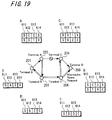
FIG. 19 is a diagram showing a route when a terminal E
transfers the request of the alternative route and the contents
of the route table 610 in each terminal;
FIG. 20 is a diagram showing a route when the terminal D
transmits a reply to the request of the alternative route and
the contents of the route table 610 in each terminal;
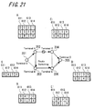
FIG. 21 is a diagram showing a route when the terminal A
transmits a command to switch a possible alternative route to a
qualified route and the contents of the route table 610 in each
terminal;
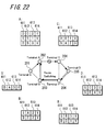
FIG. 22 is a diagram showing a route when the terminal D
transmits a command to switch a possible alternative route to a
qualified route and the contents of the route table 610 in each
terminal;
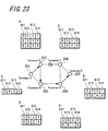
FIG. 23 is a diagram showing a state in which a route is
switched to an alternative route between the terminal S and the
terminal D and the contents of the route table 610 in each
terminal;
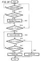
FIG. 24 is a flow chart showing a processing procedure when
the wireless terminal 100 in the embodiment of the present
invention receives the route information notification packet
830;
FIG. 25 is a flow chart showing a processing procedure when
the wireless terminal 100 in the embodiment of the present
invention receives the route error packet 840;
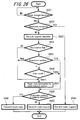
FIG. 26 is a flow chart showing a processing procedure when
the wireless terminal 100 in the embodiment of the present
invention receives the route request packet 810;
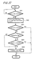
FIG. 27 is a flow chart showing a processing procedure when
the wireless terminal 100 in the embodiment of the present
invention receives the route reply packet 820; and
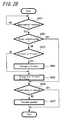
FIG. 28 is a flow chart showing a processing procedure when
the wireless terminal 100 in the embodiment of the present
invention receives the route switching packet 850.
BEST MODE FOR CARRYING OUT THE INVENTION
Next, embodiments of the present invention are explained in
detail by referring to the accompanied drawings.
FIG. 1 is a diagram showing an example of a wireless ad hoc
network that is assumed in a wireless ad hoc communication
system according to the embodiment of the present invention. In
an example of this FIG. 1A, six terminals of a terminal S (201)
through a terminal E (206) constitute a network of the wireless
ad hoc communication system. In addition, a dotted line around
each terminal indicates communication ranges 291 through 296 of
the terminals 201 through 206, respectively.
For example, the terminal A (202) and terminal B (203) are
included in the communication range 291 of the terminal S (201).
In addition, the terminal S (201), terminal B (203), and
terminal C (204) are included in the communication range 292 of
the terminal A (202). Also, the terminal S (201), terminal A
(202), and terminal E (206) are included in the communication
range 293 of the terminal B (203). Also, the terminal A (202),
terminal D (205), and terminal E (206) are included in the
communication range 294 of the terminal C (204). Moreover, the
terminal C (204) and terminal E (206) are included in the
communication range 295 of the terminal D (205). Further, the
terminal B (203), terminal C (204), and terminal D (205) are
included in the communication range 296 of the terminal E (206).
FIG. 1B schematically shows such a relation among the
terminals. In FIG. 1B, terminals existing within the
communication ranges of 291 through 296 are mutually connected
by lines. Therefore, it is understood that communication should
be performed by a plurality of hops through other terminals when
the communication is performed between terminals that are not
connected directly.
FIGS. 2A and 2B are diagrams showing a procedure for
setting a route in the wireless ad hoc network according to the
example of FIG. 1. In the case where a route is not yet set
between certain terminals, the prior art can be used as a
procedure for setting the route at the beginning. For example,
in the above-described AODV protocol, a route is set by
transmitting a route request message from a source terminal to a
destination terminal and by transmitting a route reply message
from the destination terminal to the source terminal.
FIG. 2A shows a flow of a packet when a route request is
made from the terminal S (201) to the terminal D (205). The
terminal S enters a route discovery process if a route to the
terminal D is not yet set at the time of transmitting data to
the terminal D. First, the terminal S broadcasts a route request
message (Route REQuest message: RREQ). The terminal A (202) and
terminal B (203) receiving this route request message set a
reverse path (Reverse Path) to the terminal S that is a
transmission source of the route request message. Here, the
reverse path means a path in which a neighbor terminal having
transmitted the route request message is made into the next
transfer destination when there arises a request that data is to
be transmitted to the transmission source of the route request
message.
The terminal A and terminal B which have received the route
request message further broadcast the route request message
since a destination is not these terminals. Hence, the route
request message is conveyed to the terminal C (204) and terminal
E (206). On the other hand, the route request message
broadcasted by the terminal A is also received in the terminal S
and terminal B, however, the received message is discarded in
the terminal S and terminal B since a request identifier
attached to the route request message matches. Similarly, the
route request message broadcasted by the terminal B is discarded
in the terminal S and terminal A. Thus, the request identifier
is used for checking duplicated receipt.
The terminal C and terminal E which have received the route
request message further broadcast the route request message
after setting a reverse path to the terminal S. Hence, the route
request message reaches the terminal D (205). Although the
terminal D receives the route request messages from both of the
terminal C and the terminal E, the route request message which
is received later is discarded.
FIG. 2B shows a flow of a packet when a route reply is made
from the terminal D to the terminal S. The terminal D transmits
a route reply message (Route REPly message: RREP) by a uni-cast
to the terminal S that is the transmission source, after setting
the reverse path to the terminal S. For example, when the
terminal D replies to the route request message from the
terminal C, the terminal D transmits the reply by the uni-cast
to the terminal C as a next transmission destination.
The terminal C having received the route reply message sets
a reverse path to the terminal D that is the transmission source
of the route reply message. Then, the terminal C transfers the
route reply message to the terminal A. Similarly, the terminal A
having received the route reply message sets a reverse path to
the terminal D that is the transmission source of the route
reply message, and transfers the route reply message to the
terminal S.
The terminal S having received the route reply message sets
a reverse path to the terminal D that is the transmission source
of the route reply message. Hence, the route discovery process
is completed.
FIG. 3 is a diagram showing an outline of processing in the
embodiment of the present invention. As already explained in FIG.
2, if the route to the destination address is not yet set when a
data communication request 10 is generated, the terminal enters
a route discovery process 20. Hence, the route is set between
terminals. The route among terminals is formed by passing
through at least one link 30 that mutually connects the
terminals.
After the route is set, the link is monitored by a link
state management process 40. Specifically, an item called a link
state in a route entry of a route table in each terminal is
updated appropriately. Each terminal retains information on a
link for connecting thereto in the route table as described
later, and this route table is updated whenever the link state
changes. Accordingly, each terminal can obtain the latest link
state without fail.
When the link state of the route being used becomes a
predetermined state, this link state is notified to the
transmission source in a route information notification process
50. For example, when the quality of the link deteriorates due
to some reason, a terminal on the transmission side connecting
to the link transmits a route information notification to the
transmission source. A terminal having received this route
information notification starts retaining data in a data buffer
provided therein. In addition, this route information
notification is transferred successively between each terminal
toward the transmission source.
When the link state of the route being used becomes the
predetermined state, an alternative route is searched in an
alternative route search process 60. For example, when the
quality of the link deteriorates due to some reason, the
terminal on the transmission side connecting to the link
transmits a route request in order to discover an alternative
route. The terminal which has transmitted the route request
receives a route reply in accordance with a predetermined
procedure, and thereby a possible alternative route is set.
However, when an appropriate alternative route is not
discovered for this route request, a route error is transmitted
to the next terminal on the route toward the transmission source.
Then, a terminal that has received this route error transmits a
route request in order to discover an alternative route. When an
appropriate alternative route is not discovered even by this
request, the route error is transferred further to the following
terminal on the route toward the transmission source and a
similar procedure is repeated until an alternative route is
discovered.
When the link state of the route being used becomes the
predetermined state after the possible alternative route is set,
a switching to the alternative route is made in a route
switching process 70. For example, when the quality of the link
is further deteriorated and a break of the link is about to
occur due to the same reason, the terminal having made the
possible alternative route set gives another terminal a command
to switch to the possible alternative route as a qualified route.
With this, the alternative route becomes the qualified route to
the destination terminal.
Next, a configuration example of a wireless terminal in the
embodiment of the present invention is explained by referring to
the accompanied drawing.
FIG. 4 is a diagram showing a configuration example of a
wireless terminal 100 in the embodiment of the present invention.
This wireless terminal 100 includes a communication processing
unit 110, a controller 120, a display unit 130, an operation
unit 140, and a memory 600, which are mutually connected by a
bus 180. In addition, an antenna 105 is connected to the
communication processing unit 110. The communication processing
unit 110 makes a frame of a network interface layer (data link
layer) from a signal that is received through the antenna 105.
Further, the communication processing unit 110 transmits the
frame of the network interface layer through the antenna 105.
Also, the communication processing unit 110 detects a
signal/noise ratio (S/N ratio) with respect to the signal
received through the antenna 105 and notifies to the controller
120.
The controller 120 controls the whole of the wireless
terminal 100. For example, predetermined processing is performed
by referring to the frame made by the communication processing
unit 110. The controller 120 has a timer 125 and measures time.
In addition, the controller 120 calculates an error rate of a
frame or packet.
The display unit 130 is provided to display predetermined
information, and a liquid crystal display or the like is used,
for example. The operation unit 140 is provided to make an
operation command to the wireless terminal 100 from the outside,
and a keyboard, button switch, or the like is used, for example.
The memory 600 is provided to retain data necessary for an
operation of the controller 120, and contains a route table 610
to retain information on a route for connecting this terminal
and a data buffer 620 to retain data that is transmitted to
another terminal as explained in the followings.
FIG. 5 is a diagram showing a configuration example of the
route table 610 retained in the wireless terminal 100 in the
embodiment of the present invention. The route table 610 retains
as a route entry a destination address 611, a transfer
destination address 612, the number of destination hops 613, a
link state 614, a sequence number 615, a owner 616, and a
preceding list 617. The destination address 611 shows an address
of a final destination terminal of that route. Here, the address
is only required to be the one which identifies a terminal
uniquely, and a MAC (Media Access Control) address, IP (Internet
Protocol) address, or the like can be used, for example. The
transfer destination address 612 shows an address of the next
terminal for transfer in order to reach the corresponding
destination address 611.
The number of destination hops 613 shows the number of
necessary links in order to reach the corresponding destination
address 611. For example, in case of the example of FIG. 1B, the
number of hops becomes 2, because it is necessary to pass two
links in total through the terminal A along the path to reach
the terminal S from the terminal C. The link state 614 shows a
state of a link with respect to a link to the corresponding
transfer destination address 612. This link state will be
explained later.
The sequence number 615 is provided to avoid a loop that
might be generated between a route formed in the past and a
route newly formed. It is possible to judge which route is the
newly formed one by numerically comparing a size of this
sequence number 615.
The owner 616 shows an owner of a corresponding link. Since
terminals connected to one link exist on both ends (which means
two) of the link, there is a possibility that two terminals
starts an action all at once when a change occurs in a state of
the link. Then, an owner is appointed to each link so that the
owner has a responsibility to manage the link. It is necessary
to appoint uniquely which terminal becomes the owner. For
example, it is possible to compare the IP addresses (or, MAC
addresses) by numerical values and to set a owner flag of that
route to the larger one at a stage where the route is set. In
addition, it is also possible to determine based on the number
of neighbor terminals, the performance of the terminal, and the
like other than the numerical size of the address. Since a
possibility of possessing a plurality of alternative routes is
high in a node having many neighbor terminals and since
calculation costs spent on a process for a discovery of an
alternative route become low in a terminal having a high
performance, those node and terminal are considered to be
eligible as the owner of the route. Here, in the example of FIG.
5, a case of being a owner is indicated as "1" and a case of
being not an owner is indicated as "0".
The preceding list 617 is one that shows an address group
of terminals in a reverse direction to the destination address
611 on that route. For example, in the case where there is a
route directed to the terminal S from the terminal D through the
terminal C and further through the terminal A, the preceding
list 617 of the route entry, in which the terminal S is the
destination address 611 and the terminal A is the transfer
destination address 612, contains the terminal D in the route
table 610 of the terminal C. Here, when there is additionally a
flow of data directed to the terminal S from a terminal X
through the terminal C and further through the terminal A, for
example, that preceding list 617 further contains the terminal X.
Next, a state transition of a link state in the embodiment
of the present invention is explained by referring to the
accompanied drawing.
FIG. 6 is a diagram showing an example of a state
transition in the link state management process 40 according to
the embodiment of the present invention. As a link state, it is
assumed that there are five kinds of state: a valid state (V-state:
Valid) 41, an invalid state (I-state: Invalid) 42, a
break state (B-state: Break) 43, a stretched state (S-state:
Stretched) 44, and a candidate state (C-state: Candidate) 45.
The valid state 41 is a state of being set as a qualified
route. The invalid state 42 is a state where although not used
as a route, the route entry is retained in the route table 610.
On the other hand, the break state 43 is a state where the route
is not used either, and the route entry is already deleted from
the route table 610. With this break state 43 being assumed, the
route entry can be minimized to increase an available memory and
management costs can be reduced.
The stretched state 44 is the state where a link having
been the valid state 41 until then becomes unstable due to a
deterioration of the link quality. For example, a case where a
reception state of a radio wave becomes deteriorated, a case
where a radio wave becomes difficult to pass through due to
shield by a human body, and the like are considered. However, it
is assumed that even this stretched state 44 is not such a state
that communication is completely impossible although there is
some problem in the communication. The candidate state 45 is a
state of being set as a possible alternative route by the
alternative route search process 60, and is a state of being not
yet used as a qualified route at this point of time although
this route is usable.
First, a route becomes the valid state 41 when the route is
set in the route discovery process 20, but thereafter a
transition is made to the stretched state 44 when the quality of
the link deteriorates. Further, when predetermined time passes
without using the route in the valid state 41, a transition is
made to the invalid state 42 as time out. Further, when the
alternative route switches to the qualified route, with respect
to the former link of the valid state 41 a transition is made to
the invalid state 42.
When the route turns to the stretched state 44, an
alternative route is discovered by the alternative route search
process 60. When the alternative route switches to the qualified
route, with respect to the former link of the stretched state 44
a transition is made to the invalid state 44. Further, when the
predetermined time passes without using the route in the
stretched state 44, a transition is made to either the invalid
state 42 or break state 43 with the time out. Note that a
transition is made to the break state 43 when the quality of the
link further deteriorates in the stretched state 44 such that
the link becomes a state completely incapable of performing the
communication, but the route again returns to the valid state 41
when the quality of the link becomes improved.
When the alternative route switches to the qualified route
in the candidate state 45, a transition is made to the valid
state 41. On the other hand, when the quality of the link is
further deteriorated in the candidate state 45 such that the
link becomes a state completely incapable of performing the
communication, or when the predetermined time passes without
being used, a transition is made to the break state 43 with time
out and the route is deleted from the route table 610.
Further, when the quality of the link deteriorates further
in the invalid state 42 such that the link becomes a state
completely incapable of performing the communication, or when
the predetermined time passes while leaving the route unused, a
transition is made to the break state 43 and is deleted from the
route table 610. On the other hand, it is assumed that with
respect to the valid state 41 a transition to the stretched
state 44 is made without fail and the transition is not directly
made to the break state 43 even when the quality deteriorates
abruptly to a level where the communication is not possible.
Note that whether the quality of the link is excellent or
not in this state transition is judged by the controller 120
based on a signal/noise ratio of a physical layer that is
detected by the communication processing unit 110 and an error
rate of a MAC sub-layer that is calculated by the controller 120.
In addition, the judgment of the time out is made on the basis
of the timer 125 of the controller 120.
Next, a packet configuration in the embodiment of the
present invention is explained by referring to the accompanied
drawing.
FIG. 7 is a diagram showing a configuration example of a
route information notification packet 830 that is used in the
route information notification process 50 according to the
embodiment of the present invention. When with respect to the
link state 614 in the route table 610 a transition is made from
the valid state (V-state) 41 to the stretched state (S-state) 44,
the route information notification packet 830 is transmitted by
a terminal on the transmission side, which is connected to the
link. This route information notification packet 830 contains a
packet type 831, a link state 832, a source address 833, an
upstream address 834, a downstream address 835, and a data
retention time 836.
The packet type 831 is a field that indicates a type of a
packet, and in case of this route information notification
packet 830, it is indicated that this packet is the route
information notification packet. The link state 832 is a field
that indicates a present link state of that link. In the
embodiment of the present invention, either one of the valid
state (V-state) 41 or stretched state (S-state) 44 is assumed as
this link state 832, but transmission may be made possible even
in a state other than the above-described states.
The source address 833 is a field that indicates an address
of a terminal which transmits data using that route. The
upstream address 834 and downstream address 835 are fields that
indicate addresses of terminals which specify a link having the
link state 832. Specifically, the upstream address 834 is a
terminal on the transmission side which is connected to that
link and indicates an address of a terminal that transmits the
route information notification packet 830. Also, the downstream
address 835 is a terminal on the reception side which is
connected to that link, and indicates an address of a terminal
corresponding to the next hop of the terminal that transmits the
route information notification packet 830.
The data retention time 836 is a field that designates how
long a terminal having received the route information
notification packet 830 should retain data under transmission in
the data buffer 620 (FIG. 4). For example, it is possible to
indicate that data should be retained for a duration from
several milliseconds to several seconds. On the other hand, when
data should not be retained, a value "0" is set in this data
retention time 836. When a route error message is not received
during a period of this data retention time 836 after receiving
the route information notification packet 830, the wireless
terminal 100 discards the data retained in the data buffer 620.
FIG. 8 is a diagram showing a configuration example of a
route request packet 810 that is used in the alternative route
search process 60 according to the embodiment of the present
invention. When with respect to the link state 614 in the route
table 610 a transition is made from the valid state (V-state) 41
to the stretched state (S-state) 44, the route request packet
810 is transmitted by a terminal on the transmission side which
is connected to that link. This route request packet 810
contains a packet type 811, an alternative flag 812, a hop count
813, a request identifier 814, a destination address 815, a
destination sequence number 816, a source address 817, an agent
address 818, and a source sequence number 819.
The packet type 811 is a field that indicates a type of a
packet, and in case of this route request packet 810, it is
shown that this packet is the route request packet. The
alternative flag 812 is a field that indicates whether the route
request packet 810 is used for initial route setting or is used
for setting a possible alternative route. For example, when the
alternative flag 812 is "OFF", the packet is a normal route
request and when the alternative flag is set to "ON", the packet
is a particular route request for setting a possible alternative
route. The route request packet 810 in which the alternative
flag 812 is set is transferred to other terminals than in the
stretched state 44 by multiple uni-casts. Further, in a terminal
having received the route request packet 810 in which the
alternative flag 812 is set, route information on a route
request source is formed without being restricted by limitations
on the sequence number and the number of hops which are
described later.
The hop count 813 is a field that indicates the number of
links passed through from the source address 817. The request
identifier 814 is a field that indicates an identifier for
uniquely identifying the route request relating to the route
request packet 810. This request identifier 814 is not changed
during a process in which the route request is transferred from
the source address 817 to the destination address 815.
The destination address 815 is a field that indicates an
address of a terminal that becomes a final destination of a
route to be set, and this destination address 815 indicates an
address of a final destination terminal of the route request
packet 810. The route to the destination address 815 is set with
this route request packet 810. The destination sequence number
816 is a field that indicates the maximum sequence number which
a terminal on the route toward the destination address 815 has
received in the past.
The source address 817 is a field that indicates an address
of a terminal which becomes a start of the route to be set. This
source address 817 indicates an address of a source terminal
which has first transmitted the route request packet 810 when
the alternative flag 812 is not set, but the source address 817
indicates the address of the source terminal which the following
agent address 818 has first transmitted the route request packet
810 when the alternative flag 812 is set. The agent address 818
is a field that indicates an address of a terminal which has
transmitted the route request packet 810 as an agent when the
alternative flag 812 is set.
The source sequence number 819 is a field that indicates
the present sequence number of the source terminal, and becomes
a destination sequence number for a terminal which has set a
route toward that source terminal.
FIG. 9 is a diagram showing a configuration example of the
route reply packet 820 which is used in the alternative route
search process 60 according to the embodiment of the present
invention. This route reply packet 820 is transmitted by the
terminal shown in the destination address 815 of the route
request packet 810 as a reply to the route request packet 810.
This route reply packet 820 contains a packet type 821, an
alternative flag 822, a hop count 823, a destination address 825,
a destination sequence number 826, a source address 827, an
agent address 828, and remaining time 829.
The packet type 821 is a field that indicates a type of a
packet, and in case of this route reply packet 820, it is
indicated that this packet is the route reply packet. Similarly
to the alternative flag 812, the alternative flag 822 is a field
that indicates whether the route reply packet 820 is used for
initial route setting or is used for setting a possible
alternative route. The route reply packet 820 in which this
alternative flag 822 is set is not transferred any further after
this packet is received by the terminal shown in the agent
address 818.
The hop count 823 is a field that indicates the number of
links passed through from the destination address 825. The
destination address 825 is a field that indicates an address of
a terminal which becomes a final destination of a route to be
set, and the destination address 825 indicates an address of a
terminal which has transmitted route reply packet 820. The
destination sequence number 826 is a field that indicates the
maximum sequence number which a terminal on the route toward the
destination address 825 has received in the past.
The source address 827 is a field that indicates an address
of a terminal which becomes a start of the route to be set. The
agent address 828 is a field that indicates an address of a
terminal which becomes a final destination of the route reply
packet 820 when the alternative flag 822 is set. The remaining
time 829 is a field that indicates remaining time of the route,
and is used to judge the above-described time out.
FIG. 10 is a diagram showing a configuration example of a
route error packet 840 which is used in the alternative route
search process 60 according to the embodiment of the present
invention. This route error packet 840 is transmitted by a
terminal on the transmission side which is connected to the link
in the case where an alternative route is not discovered even
though the alternative route is searched in the alternative
route search process 60, using the quality deterioration of the
link as a trigger. This route error packet 840 contains a packet
type 841 and an un-reached destination address 842. The packet
type 841 is a field that indicates a type of a packet, and in
case of this route error packet 840, it is indicated that this
packet is the route error packet.
The un-reached destination address 842 is a field that
indicates a destination address of a route that can not be
discovered even though an alternative route is searched in a
transmission terminal of the route error packet 840. A terminal
having received the route error packet 840 refers to this un-reached
destination address 842, changes the link state 614 from
the valid state to the stretched state in the route entry that
corresponds to the destination address 611 (FIG. 5) of the route
table 610, and searches an alternative route from the terminal.
In the case where the alternative route can not be discovered
even by this search, the link state 614 of the route entry is
changed from the stretched state to the invalid state (or,
deleted) and the route error packet 840 is transferred to the
address written in the preceding list 617.
FIG. 11 is a diagram showing a configuration example of the
route switching packet 850 which is used in the route switching
process 70 according to the embodiment of the present invention.
This route switching packet 850 is transmitted by a terminal
having transmitted the route request packet 810 for setting a
possible alternative route in order to switch to the possible
alternative route as a qualified route. A normal data packet can
be used as the route switching packet 850. For example, as shown
in FIG. 11, this packet can be obtained by partly changing a
definition of a header portion 851 in a data packet that
contains data 857 in a payload portion 856. However, in the case
where a header portion can not be changed in such a case of IPv4,
a data packet may be transmitted after the route switching
packet 850 that contains similar information is transmitted as a
control packet.
In the header portion 851 of the route switching packet 850
using the data packet, a route switching flag 854 is provided in
addition to a normal destination address 852 and source address
853. A terminal having received a data packet in which the route
switching flag 854 is set to "ON" switches a possible
alternative route to a qualified route. Specifically, a route
entry in which the destination address 611 corresponds to the
destination address 852 is searched in the route table 610, and
the link state 614 in such route entry is changed from the
candidate state 45 to the valid state 41. Further, prior to the
above, the link state 614 is changed to the invalid state 42 if
there is one whose link state 614 is either the valid state 41
or stretched state 44 in the route entry in which the
destination address 611 corresponds to the destination address
852.
Next, an operation in each process in the embodiment of the
present invention is explained by referring to the accompanied
drawing.
FIG. 12 is a diagram showing a route when the terminal C
transmits the route information notification packet 830 in the
embodiment of the present invention. Here, it is assumed that a
route passing through the terminal A, terminal B, and terminal C
is used when transmission of data is performed from the terminal
S to the terminal D. When the quality of the link between the
terminal C and the terminal D deteriorates to become a stretched
state, the terminal C transmits the route information
notification packet 830 to the terminal B. In this case, the
source address 833 shows the address of the terminal S that is a
data transmission source, the upstream address 834 shows the
address of the terminal C that transmits this route information
notification packet 830, and the downstream address 835 shows
the address of the terminal D that is the next hop, respectively,
in the route information notification packet 830 shown in FIG. 7.
As the link state 832, it is shown that the link state is the
stretched state.
The terminal B having received this route information
notification packet 830 retains data to be transmitted
thereafter to the terminal C in the data buffer 620 thereof. The
terminal B transfers this route information notification packet
830 further to the upstream terminal A. Hence, the terminal A
also starts retaining data to be transmitted thereafter to the
terminal B in the data buffer 620 thereof. Similarly, the
terminal A transfers this route information notification packet
830 further to the upstream terminal S. Hence, the terminal S
also starts retaining data to be transmitted thereafter to the
terminal A in the data buffer 620 thereof. Since the terminal S
is a transmission source of the data and the source address 833
corresponds to the address thereof, the terminal S does not
transfer this packet any further.
FIG. 13 is a diagram showing a route when the terminal C
transmits the route error packet 840 in the embodiment of the
present invention. After the terminal C transmits the route
information notification packet 830 in FIG. 12, the terminal C
transmits the route request packet 810 in order to search an
alternative route in place of the route between the terminal C
and the terminal D which is the stretched state. Viewing from
the terminal C, neighbor terminals other than the terminal D are
the terminal B and terminal G. Since the terminal B is included
in the preceding list 617 of the present route, a route passing
through the terminal B is not searched at this stage. Here, if a
route between the terminal C and the terminal G is already
broken as shown in FIG. 13, a route passing through the terminal
G can not be discovered, either. Therefore, the terminal C can
not discover any other route. Then, the terminal C transmits the
route error packet 840 to the terminal B.
The terminal B having received this route error packet 840
transmits the route request packet 810 in order to search an
alternative route between the terminal B and the terminal D.
Viewing from the terminal B, neighbor terminals other than the
terminal C are the terminal A and terminal F. Since the terminal
A is included in the preceding list 617 of the present route, a
route passing through the terminal A is not searched at this
stage. Here, if a route between the terminal F and the terminal
G and a route between the terminal F and the terminal I are
already broken as shown in FIG. 13, the terminal B can not
discover any other route. Then, the terminal B transfers the
route error packet 840 to the terminal A.
The terminal A having received this route error packet 840
transmits the route request packet 810 in order to search an
alternative route between the terminal A and the terminal D.
Viewing from the terminal A, neighbor terminals other than the
terminal B are the terminal S and terminal E. Since the terminal
S is included in the preceding list 617 of the present route, a
route passing through the terminal S is not searched at this
stage. With respect to the terminal E, a route to the terminal F
is broken but a route to the terminal H is connected as shown in
FIG. 13. The route request packet 810 transmitted from the
terminal A is transferred until the packet reaches the terminal
D from the terminal E, through the terminal H, terminal I, and
terminal J. During this process, a route toward the terminal S
from the terminal D is set in the route tables 610 in the
terminals on the route. At this stage, the link state 614 on
this route is a candidate state.
The terminal D having received the route request packet 810
transmits the route reply packet 820 to the terminal J. This
route reply packet 820 is transferred in a reverse direction to
the route in which this route request packet 810 has been
transferred. During this process, a route toward the terminal D
from the terminal S is set in the route tables 610 in the
terminals on the route. At this stage, the link state 614 on
this route is the candidate state.
FIG. 14 is a diagram showing a state in which the route is
switched to the alternative route between the terminal S and the
terminal D in the embodiment of the present invention. As
described above, the link state 614 on the route is the
candidate state at the stage where the alternative route has
been set by the route request packet 810 and route reply packet
820. The terminal A transmits the route switching packet 850 to
the terminal E in order to make this route switched into a
qualified route. The terminal E on the alternative route having
received this route switching packet 850 changes the link of the
candidate state into a valid state after changing the former
route into an invalid state. Further, this route switching
packet 850 is transferred until the packet reaches the terminal
D from the terminal E, through the terminal H, terminal I, and
terminal J. Hence, the alternative route is switched to be the
qualified route.
FIG. 15 is a diagram showing data transmission timing of
the terminal A before and after a route information notification
in the embodiment of the present invention. FIG. 15A shows a
flow of data when the data is transmitted from the terminal A to
the terminal B. Assuming that the route information notification
packet 830 is received when the terminal A has transmitted data
from d1 to d3, data on and after d4 is transmitted to the
terminal B, and also is retained in the data buffer 620 of the
terminal A as shown in FIG. 15B.
Assuming that the route switching packet 850 that the route
is switched to the terminal E is received when the terminal A
has transmitted data d6, the terminal A next transmits data to
the terminal E. At this time, the terminal A first transmits
data from d4 to d6 which have been retained in the data buffer
620 before transmitting the next data d7. Then, the terminal A
successively transmits data on and after d7 to the terminal E
after the transmission of the data from d4 to d6 which have been
retained in the data buffer 620 is completed to the terminal E.
In this way, the transmission data during the switching can be
transmitted without omission at the time of the route switching.
Here, although there is a possibility as a result that the data
from d4 to d6 transmitted by the former route through the
terminal B is received in duplicate by the terminal D, a problem
does not occur since the terminal D discards the data reached
later in that case.
Next, operations of the alternative route discovery process
50 and route switching process 60 in the embodiment of the
present invention are explained by referring to the accompanied
drawings.
FIG. 16 is a diagram showing a route when communication is
performed toward the terminal D from the terminal S and the
contents of the route table 610 in each terminal. The terminal A
and terminal C transfer a packet between the terminal S and the
terminal D. At this time, in the route table 610 of the terminal
S, the transfer destination address 612 is the terminal A in a
route entry in which the terminal D is the destination address
611. Further, in the route table 610 of the terminal A, the
transfer destination address 612 is the terminal C in a route
entry in which the terminal D is the destination address 611,
and the transfer destination address 612 is the terminal S in a
route entry in which the terminal S is the destination address
611. Further, in the route table 610 of the terminal C, the
transfer destination address 612 is the terminal D in a route
entry in which the terminal D is the destination address 611,
and the transfer destination address 612 is the terminal A in a
route entry in which the terminal S is the destination address
611. In addition, in the route table 610 of the terminal D, the
transfer destination address 612 is the terminal C in a route
entry in which the terminal S is the destination address 611.
Further, the link state for all of the above is the valid state
41.
Here, an assumption is made to a case where the quality of
the link between the terminal A and the terminal C deteriorates
to become an stretched state. If the terminal A is an owner of
this link, for example, the terminal A discovers an alternative
route in the following procedure.
FIG. 17 is a diagram showing a route and the contents of
the route table 610 in each terminal when the terminal A
requests an alternative route. Since the quality of the link
between the terminal A and the terminal C has deteriorated, the
link state 614 has changed from the valid state 41 to the
stretched state 44 with respect to the route to the terminal D
in the route table 610 of the terminal A and the route to the
terminal S in the route table 610 of the terminal C.
The terminal A transmits by multiple uni-casts the route
request packet 810 (FIG. 7) in which the alternative flag 812 is
set. However, in case of this example, the transmission becomes
the uni-cast transmission to the terminal B. The reason is that
the link to the terminal C is the stretched state, also the
terminal S is written in the preceding list 617 (FIG. 5), and
therefore the terminal A does not transmit the route request
packet 810 to the terminal S and terminal C. Further, the
address of the terminal S which is a start of the route is
written in the source address 817 of this route request packet
810.
The terminal B having received the route request packet 810
from the terminal A forms a route entry in which the destination
address 611 is the terminal S and the transfer destination
address 612 is the terminal A as a route toward the source
address 817, and sets the link state 614 to the candidate state
45.
FIG. 18 is a diagram showing a route and the contents of
the route table 610 in each terminal when the terminal B
transfers the request of the alternative route. The terminal B
having received the route request packet 810 from the terminal A
forms the route entry as described above, and then transfers the
route request packet 810 to the terminal S and terminal E.
Similarly to the above, the terminal S having received the route
request packet 810 interprets that this route request packet is
the packet transmitted therefrom and discards this route request
packet 810.
The terminal E having received the route request packet 810
from the terminal B forms a route entry in which the destination
address 611 is the terminal S and the transfer destination
address 612 is the terminal B as the route toward the source
address 817, and sets the link state 614 to the candidate state
45.
FIG. 19 is a diagram showing a route and the contents of
the route table 610 in each terminal when the terminal E
transfers the request of the alternative route. The terminal E
having received the route request packet 810 from the terminal B
forms the route entry as described above, and then transfers the
route request packet 810 further to the terminal C and terminal
D.
The terminal D having received the route request packet 810
from the terminal E forms a route entry in which the destination
address 611 is the terminal S and the transfer destination
address 612 is the terminal E as the route toward the source
address 817, and sets the link state 614 to the candidate state
45. Note that the terminal D receives thereafter the route
request packet 810 from the terminal C but discards the route
request packet 810 transmitted from the terminal C since the
request identifier 814 of the route request packet 810
corresponds to the one previously received from the terminal E.
FIG. 20 is a diagram showing a route and the contents of
the route table 610 in each terminal when the terminal D
transmits a reply to the request of the alternative route. The
terminal D having received the route request packet 810 from the
terminal E forms the route entry as described above, and then
toward the terminal S transmits the route reply packet 820 (FIG.
9) in which the alternative flag 822 is set, as a reply to that
route request packet 810. The destination address 825, source
address 827, and agent address 828 of this route reply packet
820 correspond to the destination address 815, source address
817, and agent address 818 of the route request packet 810,
respectively.
The route reply packet 820 from the terminal D is
transferred in a similar procedure to the route request packet
810, and an alternative route is formed in each terminal.
Specifically, the terminal E forms a route entry in which the
destination address 611 is the terminal D and the transfer
destination address 612 is the terminal D, and sets the link
state 614 to the candidate state 45. The terminal B forms a
route entry in which the destination address 611 is the terminal
D and the transfer destination address 612 is the terminal E,
and sets the link state 614 to the candidate state 45. In
addition, the terminal A forms a route entry in which the
destination address 611 is the terminal D and the transfer
destination address 612 is the terminal B, and sets the link
state 614 to the candidate state 45.
Since the alternative flag 822 is set and the agent address
828 is the address thereof, the terminal A receives the route
reply packet 820 and does not transfer any further. Thus, the
possible alternative route is set between the terminal S and the
terminal D. Note that a route error packet is transmitted to the
terminal A when there exists no route to be the alternative.
FIG. 21 is a diagram showing a route and the contents of
the route table 610 in each terminal when the terminal A
transmits a command to switch a possible alternative route to a
qualified route. When switching to the alternative route is
selected, and when there is a route entry in which the
destination address 611 is the terminal D and whose link state
614 is a stretched state or valid state in the route table 610
thereof, the terminal A first sets the link state 614 to an
invalid state by using a data communication request generated
thereafter as a trigger. Further, the link state 614 is set to a
valid state for a route entry in which the destination address
611 is the terminal D and whose link state 614 is a candidate
state. Specifically, the link state 614 of the route in which
the transfer destination address 612 is the terminal C is
changed from the stretched state to the invalid state, the link
state 614 of the route in which the transfer destination address
612 is the terminal B is changed from the candidate state to the
valid state. Further, the terminal A transmits the route
switching packet 850 directed to the terminal D to the terminal
B by referring to the route table 610 in which the link state
614 is thus changed.
The terminal B having received the route switching packet
850 from the terminal A changes the link state 614 of the route
in which the transfer destination address 612 is the terminal E
from the candidate state to the valid state. The terminal B
transfers the route switching packet 850 to the terminal E by
referring to the route table 610 in which the link state 614 is
thus changed.
The terminal E having received the route switching packet
850 from the terminal B changes the link state 614 of the route
in which the transfer destination address 612 is the terminal D
from the candidate state to the valid state. The terminal E
transfers the route switching packet 850 further to the terminal
D by referring to the route table 610 in which the link state
614 is thus changed. In this manner, a route table in the
forward direction is set when the route switching packet 850
transmitted by the terminal A reaches the terminal D.
FIG. 22 is a diagram showing a route and the contents of
the route table 610 in each terminal when the terminal D
transmits a command to switch a possible alternative route to
the qualified route. The terminal D having received the route
switching packet 850 from the terminal E changes the link state
614 of the route in which the transfer destination address 612
is the terminal C from the valid state to the invalid state and
changes the link state 614 of the route in which the transfer
destination address 612 is the terminal E from the candidate
state to the valid state by using a data communication request
generated thereafter as a trigger. Further, the terminal D
transmits this time the route switching packet 850 directed to
the terminal S to the terminal E by referring to the route table
610 in which the link state 614 is thus changed.
The terminal E having received the route switching packet
850 from the terminal D changes the link state 614 of the route
in which the transfer destination address 612 is the terminal B
from the candidate state to the valid state. The terminal E
transfers the route switching packet 850 to the terminal B by
referring to the route table 610 in which the link state 614 is
thus changed.
The terminal B having received the route switching packet
850 from the terminal E changes the link state 614 of the route
in which the transfer destination address 612 is the terminal A
from the candidate state to the valid state. The terminal B
transfers the route switching packet 850 further to the terminal
A by referring to the route table 610 in which the link state
614 is thus changed. In this manner, a route table in the
reverse direction is set when the route switching packet 850
transmitted by the terminal D reaches the terminal A.
FIG. 23 is a diagram showing a state where the route is
switched to the alternative route between the terminal S and the
terminal D and the contents of the route table 610 in each
terminal. When predetermined time passes in this state, or when
the link quality between the terminal A and the terminal C
further deteriorates to become a state completely incapable of
performing the communication, an unnecessary route entry in the
route table 610 is deleted by the link state management process
40. For example, there is such a possibility that the route
entry in which the transfer destination address 612 is the
terminal C is deleted in the route table 610 of the terminal A,
the route entry in which the transfer destination address 612 is
the terminal D is deleted in the route table 610 of the terminal
C, and the route entry in which the transfer destination address
612 is the terminal C is deleted in the route table 610 of the
terminal D. On the other hand, in case that the link quality
between the terminal A and the terminal C improves and the link
quality between the terminal B and the terminal E deteriorates,
there is also a possibility that the route is switched again to
the former route.
Next, a processing method in each terminal according to the
embodiment of the present invention is explained by referring to
the accompanied drawings.
FIG. 24 is a flow chart showing a processing procedure in
the case where the wireless terminal 100 in the embodiment of
the present invention receives the route information
notification packet 830. When the wireless terminal 100 receives
the route information notification packet 830 (step S911), and
when the source address 833 of the route information
notification packet 830 is not the address thereof (step S912),
the wireless terminal 100 transfers the route information
notification packet 830 toward the source address 833 (step
S913). Further, when the link state 832 of this route
information notification packet 830 is other than a stretched
state or break state (that is, a valid state, invalid state, or
candidate state) (step S914), the next route information
notification packet 830 is received (step S911).
In step S914, when it is judged that the link state 832 is
the stretched state or break state, the wireless terminal 100
retains transmission data on the present route in the data
buffer 620 (step S915). Further, when the route error packet 840
is received before the data retention time 836 passes (step
S917), an alternative route therefrom to a destination terminal
is searched (step S920). This is described later by referring to
FIG. 25.
On the other hand, when the data retention time 836 passes
(step S917) after starting the retention of data in the data
buffer 620 (step S915), the data retained in the data buffer 620
is discarded (step S918).
FIG. 25 is a flow chart showing a processing procedure when
the wireless terminal 100 in the embodiment of the present
invention receives the route error packet 840. When the route
error packet 840 is received (step S921), the wireless terminal
100 transmits the route request packet 810 in order to search an
alternative route from the terminal to the destination terminal
(step S922). When the route reply packet 820 is received with
respect to this route request packet 810, the alternative route
to the destination terminal is discovered (step S923), and so a
switching to the alternative route is performed by transmitting
the route switching packet 850 (step S960). Those procedures
from the route search to the route switching are described later
by referring to FIGS. 26 through 28.
When the route can not be discovered in step S923, the
route entry is deleted from the route table 610 or is changed to
an invalid state (step S924), and the data retained in the data
buffer 620 is discarded (step S925). Further, when the terminal
itself is not the transmission source of the data (step S926),
the route error packet 840 is transferred to the address written
in the preceding list 617 (step S927).
FIG. 26 is a flow chart showing a processing procedure when
the wireless terminal 100 in the embodiment of the present
invention receives the route request packet 810. When the
wireless terminal 100 receives the route request packet 810
(step S931), it is judged whether this route request packet is
received in duplicate by referring to the request identifier 814
of the route request packet 810 (step S932). If a route request
packet having the same request identifier has already been
received, the route request packet 810 received later is
discarded (step S943).
When it is judged in step S932 that this reception is not
duplication, the request identifier 814 of that route request
packet 810 is recorded (step S933), and is used thereafter for
judgment of the duplicated reception. Then, the alternative flag
812 of that route request packet 810 is referred to, and it is
judged whether this alternative flag 812 is set to "ON",
specifically whether this route request packet 810 is a route
request for discovering an alternative route (step S934). When
this route request packet 810 is the alternative route discovery
request, route information toward the route request source is
formed without making judgments of the following steps of S935
and S936 (step S937).
When it is judged in step S934 that this route request
packet is not the alternative route discovery request but a
normal (initial) route request, checking on the sequence number
(step S935) and checking on the hop count (step S936) are
performed. Specifically, when the destination sequence number
816 of the route request packet 810 is newer than the sequence
number 615 of the route set at present, the route information
toward the route request source is formed (step S937). On the
other hand, when the destination sequence number 816 of the
route request packet 810 is older than the sequence number 615
of the route set at present, the route information is not formed
(step S937). In addition, when the destination sequence number
816 of the route request packet 810 corresponds to the sequence
number 615 of the route set at present, the hop count 813 of the
route request packet 810 is compared with the number of
destination hops 613 of the route which is set at present, and
the route information toward the route request source is formed
(step S937) when the hop count 813 of the route request packet
810 is shorter.
When the route information toward the route request source
is formed in step S937, the following processing is specifically
performed. That is, the destination sequence number 816 of the
route request packet 810 is set to the sequence number 615, a
number in which "1" is added to the hop count 813 of the route
request packet 810 is set to the number of destination hops 613,
and an address of a neighbor terminal which has transmitted the
route request packet 810 is set to the transfer destination
address 612. In addition, the link state 614 is set to a valid
state when this route request packet is the normal (initial)
route request, but the link state 614 is set to a candidate
state when this route request packet is the alternative route
discovery request.
Further, when the destination address 815 of the route
request packet 810 is the address thereof (step S938), the route
reply packet 820 is transmitted to this route request packet 810
(step S941). On the other hand, when the destination address 815
of the route request packet 810 is not the address thereof, the
route request packet 810 is transferred to another terminal
(step S942). At this time, this route request packet is
transmitted by a broadcast when this route request packet is the
normal (initial) route request, but this route request packet is
transmitted by multiple uni-casts to terminals which are other
than the terminal connected to a link of the stretched state and
which are not written in the preceding list 617 (FIG. 5), when
this route request packet is the alternative route discovery
request.
FIG. 27 is a flow chart showing a processing procedure when
the wireless terminal 100 in the embodiment of the present
invention receives the route reply packet 820. When the wireless
terminal 100 receives the route reply packet 820 (step S951),
route information toward a transmission source of the route
reply is formed (step S952).
Further, when the source address 827 of the route reply
packet 820 corresponds to the address thereof (step S953), the
process is ended without performing further processing since it
means that a qualified route is set. On the other hand, when the
source address 827 of the route reply packet 820 does not
correspond to the address thereof, the alternative flag 822 is
further checked (step S954), and when the alternative flag 822
is not set, that route reply packet 820 is further transferred
by interpreting that as a normal route reply (step S956).
When the alternative flag 822 is set in step S954, the
agent address 828 is further checked (step S955), and when the
agent address 828 does not correspond to the address thereof,
the route reply packet 820 is further transferred (step S956).
On the other hand, when the agent address 828 corresponds to the
address thereof, the process is ended without performing further
processing since it means that a reply to the alternative route
request transmitted from the terminal itself is returned.
FIG. 28 is a flow chart showing a processing procedure when
the wireless terminal 100 in the embodiment of the present
invention receives the route switching packet 850. When the
wireless terminal 100 receives a data packet (step S961), it is
checked whether or not the route switching flag 854 of the data
packet is set (step S962). When the route switching flag 854 is
not set, a switching of the route is not performed since the
data packet is normal one.
When it is judged in step S962 that the route switching
flag 854 is set, the switching of the route is performed in the
following procedure since the data packet is the route switching
packet 850. First, in the route table 610, when there is a route
whose link state 614 is a valid state or stretched state in a
route entry in which the destination address 611 corresponds to
the destination address 852 (step S963), the link state 614 is
changed to an invalid state (step S964). Then, in the route
table 610, the link state 614 is changed from a candidate state
to a valid state in the route entry in which the destination
address 611 corresponds to the destination address 852 (step
S965).
Further, when the destination address 852 corresponds to
the address thereof (step S966), the process is ended without
performing further processing. On the other hand, when the
destination address 852 does not correspond to the address
thereof, the data packet is transferred to another terminal in
accordance with the route table 610 (step S967).
Thus, according to the embodiment of the present invention,
a state of the link 30 on the route set by the route discovery
process 20 is monitored by the link state management process 40,
and an alternative route is searched by the alternative route
search process 60 after the link state is notified by the route
information notification process 50 when the link quality
deteriorates. Accordingly, a terminal having received the
notification starts the retention of transmission data and
prepares for the switching of the alternative route thereafter
in the route switching process 70.
Also, when an alternative route is not discovered from a
certain terminal in the alternative route search process 60, a
route error is transmitted to a neighbor terminal on the
transmission side, and a terminal having received the route
error searches an alternative route. Accordingly, it is possible
to set the alternative route without deleting all the routes.
Specifically, it is possible to perform stable communication
even in an ad hoc network environment having a deteriorated
radio wave condition such that a failure of a link frequently
occurs, and a network of high reliability can be provided in
which the communication is performed continuously even in an
environment of the ad hoc network in which a movement of a node
happens frequently.
Having described preferred embodiments of the invention
with reference to the accompanying drawings, it is to be
understood that the invention is not limited thereto and that
various changes and modifications could be effected therein
without departing from the spirit or scope of the invention.
Moreover, the processing procedures described above may be
interpreted as a method having the series of procedures, and it
is also possible to interpret as a program to make these series
of procedures executed by a computer and/or a recording medium
to store that program.