EP1608044A1 - A construction and a method for connecting an intermediate connector and one or more electrical components - Google Patents
A construction and a method for connecting an intermediate connector and one or more electrical components Download PDFInfo
- Publication number
- EP1608044A1 EP1608044A1 EP05013142A EP05013142A EP1608044A1 EP 1608044 A1 EP1608044 A1 EP 1608044A1 EP 05013142 A EP05013142 A EP 05013142A EP 05013142 A EP05013142 A EP 05013142A EP 1608044 A1 EP1608044 A1 EP 1608044A1
- Authority
- EP
- European Patent Office
- Prior art keywords
- positioning
- electrical
- connector
- portions
- intermediate connector
- Prior art date
- Legal status (The legal status is an assumption and is not a legal conclusion. Google has not performed a legal analysis and makes no representation as to the accuracy of the status listed.)
- Granted
Links
Images


Classifications
-
- H—ELECTRICITY
- H01—ELECTRIC ELEMENTS
- H01R—ELECTRICALLY-CONDUCTIVE CONNECTIONS; STRUCTURAL ASSOCIATIONS OF A PLURALITY OF MUTUALLY-INSULATED ELECTRICAL CONNECTING ELEMENTS; COUPLING DEVICES; CURRENT COLLECTORS
- H01R13/00—Details of coupling devices of the kinds covered by groups H01R12/70 or H01R24/00 - H01R33/00
- H01R13/62—Means for facilitating engagement or disengagement of coupling parts or for holding them in engagement
- H01R13/629—Additional means for facilitating engagement or disengagement of coupling parts, e.g. aligning or guiding means, levers, gas pressure electrical locking indicators, manufacturing tolerances
- H01R13/631—Additional means for facilitating engagement or disengagement of coupling parts, e.g. aligning or guiding means, levers, gas pressure electrical locking indicators, manufacturing tolerances for engagement only
- H01R13/6315—Additional means for facilitating engagement or disengagement of coupling parts, e.g. aligning or guiding means, levers, gas pressure electrical locking indicators, manufacturing tolerances for engagement only allowing relative movement between coupling parts, e.g. floating connection
-
- H—ELECTRICITY
- H01—ELECTRIC ELEMENTS
- H01R—ELECTRICALLY-CONDUCTIVE CONNECTIONS; STRUCTURAL ASSOCIATIONS OF A PLURALITY OF MUTUALLY-INSULATED ELECTRICAL CONNECTING ELEMENTS; COUPLING DEVICES; CURRENT COLLECTORS
- H01R33/00—Coupling devices specially adapted for supporting apparatus and having one part acting as a holder providing support and electrical connection via a counterpart which is structurally associated with the apparatus, e.g. lamp holders; Separate parts thereof
- H01R33/74—Devices having four or more poles, e.g. holders for compact fluorescent lamps
- H01R33/76—Holders with sockets, clips, or analogous contacts adapted for axially-sliding engagement with parallely-arranged pins, blades, or analogous contacts on counterpart, e.g. electronic tube socket
- H01R33/7664—Holders with sockets, clips, or analogous contacts adapted for axially-sliding engagement with parallely-arranged pins, blades, or analogous contacts on counterpart, e.g. electronic tube socket having additional guiding, adapting, shielding, anti-vibration or mounting means
Definitions
- the present invention relates to a construction and a method for connecting an intermediate connector and one or more electrical components.
- a plurality of solenoid valves for hydraulic control are provided in a device in a casing, for example, in an automatic transmission of an automotive vehicle, and an intermediate connector for connecting these solenoid valves with an external circuitry is so provided as to penetrate the casing from the inside to the outside.
- An internal connector is fitted in a fitting portion inside the intermediate connector, and a plurality of connectors are provided at ends of wires drawn out from the internal connector and are connected with connector portions of the respective solenoid valves.
- One example of such a connecting construction is known from Japanese Unexamined Patent Publication No. H06-223903.
- the present invention was developed in view of the above problem, and an object thereof is to improve operability.
- a construction for connecting one or more electrical components arranged in or on a casing and an intermediate connector to be electrically connected with an external circuitry comprising:
- the one or more connector portions of the respective electrical components is/are at least partly fitted into the respective electrical-component fitting portions at once and the respective electrical component(s) is/are connected with the external circuitry via the intermediate connector. Accordingly, operability can be improved as compared to a case where the respective electrical components are individually connected as in the prior art. Further, at the time of the assembling, the electrical-component fitting portions and/or the electrical components provided with the aligning means are positioned in such postures fittable or insertable to the mating sides by the positioning means, and the electrical-component fitting portions and the electrical components are fitted to or connected with each other while being substantially aligned by the aligning means. Thus, the fitting operation can be smoothly carried out and, as a result, connection operability becomes better.
- a construction for connecting a plurality of electrical components arranged in a casing and an intermediate connector electrically connected with an external circuitry comprising:
- the respective electrical components are to be mounted in a device to be placed in the casing, and the positioning means comprises:
- the positioning means comprises:
- the respective electrical components are mounted in a device placed in the casing, and the positioning means comprises:
- the first positioning pin is first inserted into the first positioning recess, thereby positioning the intermediate connector and the device. Subsequently, the second positioning pins are inserted into the second positioning recesses, whereby the electrical-component fitting portions and the connector portions are aligned with each other by the aligning means while being positioned. Thus, the fitting operation can be smoothly carried out.
- each electrical component comprises the aligning means
- the positioning means comprises an alignment plate to be assembled before the intermediate connector, wherein the alignment plate is formed with one or more insertion holes through which the respective connector portion(s) is/are passed and which can support the connector portion(s) in such posture(s) at least partly fittable into the electrical-component fitting portion(s).
- the positioning means further comprises one or more guiding surfaces capable of guiding the passage of the respective connector portions through the insertion holes by being brought substantially into sliding contact with the respective connector portions at the time of the assembling are formed on at least part of the peripheral edges of the insertion holes.
- each electrical component comprises the aligning means
- the positioning means comprises an alignment plate to be assembled before the intermediate connector, wherein the alignment plate is formed with insertion holes through which the respective connector portions are passed and which can support the connector portions in such postures fittable into the electrical-component fitting portions, and guiding surfaces capable of guiding the passage of the respective connector portions through the insertion holes by being brought into sliding contact with the respective connector portions at the time of the assembling are formed on the peripheral edges of the insertion holes.
- the respective connector portions When the alignment plate is first assembled, the respective connector portions are guided by the guiding surfaces, thereby being passed through the insertion holes while being aligned by the aligning means to take such postures fittable into the electrical-component fitting portions. Thus, the connector portions are supported in the above postures. Thereafter, by assembling the intermediate connector, the respective connector portions aligned in advance are smoothly fitted into the corresponding electrical-component fitting portions. According to the present invention, it is not necessary to provide the electrical components and the intermediate connector with any special construction for positioning.
- the respective electrical components are to be mounted in a device placed in the casing and each electrical component includes the aligning means, and the positioning means comprises:
- the positioning means comprises one or more guiding portions capable of guiding the respective connector portions to such postures at least partly fittable into the electrical-component fitting portions by pressing outer surfaces of the respective connector portions as the positioning pin is moved along the positioning groove in a direction at an angle different from 0° or 180°, preferably substantially normal to an assembling direction.
- each electrical component includes the aligning means, and the positioning means comprises:
- a method for connecting one or more electrical components arranged in or on a casing and an intermediate connector to be electrically connected with an external circuitry comprising the following steps:
- the respective electrical components are mounted in a device to be placed in the casing, and the positioning means comprises:
- each electrical component comprises the aligning means
- the positioning means comprises an alignment plate which is assembled before the intermediate connector, wherein the alignment plate is formed with one or more insertion holes through which the respective connector portion(s) is/are passed and which can support the connector portion(s) in such posture(s) at least partly fittable into the electrical-component fitting portion(s), wherein the positioning means preferably further comprises one or more guiding surfaces capable of guiding the passage of the respective connector portions through the insertion holes by being brought substantially into sliding contact with the respective connector portions at the time of the assembling are formed on at least part of the peripheral edges of the insertion holes.
- each electrical component includes the aligning means, and the positioning means comprises:
- FIGS. 1 to 12 A first preferred embodiment of the present invention is described with reference to FIGS. 1 to 12.
- one or more, preferably a plurality of (two) solenoid valves 20 for hydraulic or pneumatic control are mounted in a valve body 30 placed in a casing C e.g. of an automatic transmission of an automotive vehicle, and are to be electrically connected with an external circuitry via an intermediate connector 10.
- FIGS. 3 and 4 concerning vertical direction VD while being made to directions of arrows X, Y in FIG. 1 concerning horizontal direction.
- the intermediate connector 10 includes a connector housing 11 made e.g. of a synthetic resin and having one or more, preferably a plurality of busbars arranged or embedded therein or thereon, and a part of this connector housing 11 to be mounted through an opening H formed in one surface of the casing C serves as an external-circuitry fitting or connection portion 12 connectable with an external connector (not shown) connected with the outer circuitry.
- a (preferably substantially laterally long) switchboard 14 is to be coupled to this external-circuitry fitting portion 12 by way of a (preferably substantially vertically extending) coupling portion 13, and is integrally or unitarily provided with one or more, e.g.
- Each valve fitting portion 15 preferably is substantially in the form of a rectangular tube projecting down (or towards the valve body 30) from the lower or facing surface of the switchboard 14, and a tapered or converging or rounded surface 15a is formed at least partly around the inner circumferential edge at the leading end thereof so as to guide a connecting operation of a connector portion 22.
- Bottom or distal ends of the busbars at least partly project into the valve fitting portion 15 and serve as connecting portions 15b with the solenoid valve 20.
- Two connecting portions 15b are arranged substantially side by side substantially along X-direction in each valve fitting portion 15.
- each solenoid valve 20 includes a substantially cylindrical main portion 21 having a coil (not shown) or the like inside, and is to be mounted by means of a bracket 40 with one end of the main portion 21 inserted through a side surface of the box-shaped valve body 30, so that a hydraulic pressure in a hydraulic path in the valve body 30 can be controlled or supplied.
- Two solenoid valves 20 are arranged substantially side by side substantially along X-direction.
- the substantially block-shaped connector portion 22 rectangular when viewed from above projects upward or outward at a part of the main portion 21 projecting out from the valve body 30, and a tapered surface 22a is formed around the outer circumferential edge of the leading end of this connector portion 22 in order to guide the mating movement of the connector portion 22 into the valve fitting portion 15.
- One or more, preferably a pair of terminal fittings 23 connected or connectable with lead wires of coils are at least partly accommodated preferably substantially side by side in the connector portion 22.
- One or more resilient contact pieces 23a of the terminal fittings 23 can be resiliently brought into contact with the connecting portions 15b of the intermediate connector 10.
- a mating direction MD of the connector portion 22 and the valve fitting portion 15 preferably extends along vertical direction VD, and preferably is the same direction in which the intermediate connector 10 is assembled with the valve body 30.
- Each solenoid valve 20 is so mounted as to be displaceable relative to the corresponding bracket 40 along horizontal direction in the shown example (direction at an angle different from 0° or 180°, preferably substantially normal to the mating direction MD), thereby being able to be aligned with the mating valve fitting portion 15.
- the solenoid 20 is provided with an aligning means. More specifically, the main portion 21 of the solenoid valve 20 is provided with a small-diameter portion 24 having a diameter smaller than the leading end of the main portion 21 where the connector portion 22 is provided, and the bracket 40 is mounted or mountable on this small-diameter portion 24.
- the bracket 40 preferably is substantially L-shaped as a whole, and the leading end of a vertical part 41 (or a part substantially parallel to the mating direction MD) at least partly fittable to the small-diameter portion 24 has a substantially annular shape extending along the outer circumferential surface of the small-diameter portion 24, so that the main portion 21 is rotatable or pivotable about its longitudinal axis relative to the vertical portion 41.
- the connector portion 22 is displaceable along X-direction relative to the valve fitting portion 15.
- a rotatable range of the main portion 21 can be restricted by unillustrated stoppers and can be, for example, restricted to an angle range of about 5° to left and right from a posture where the connector portion 22 is substantially vertical or aligned.
- the small-diameter portion 24 of the main portion 21 slides in contact with the vertical part 41 of the bracket 40, whereby the main portion 21 is slidable substantially along longitudinal direction (Y-direction) relative to the vertical part 41.
- the connector portion 22 is displaceable along Y-direction relative to the valve fitting portion 15.
- a horizontal part 42 of the bracket 40 is to be fixed to the valve body 30 by means of a screw or the like.
- the intermediate connector 10, the solenoid valve 20 and the valve body 30 are provided with one or more positioning means for positioning the solenoid valves 20 in such postures fittable into the valve fitting portions 15. More specifically, one or more, preferably a pair of substantially cylindrical first positioning pins 16 are so provided at (preferably substantially opposite) end position(s) of the switchboard 14 of the intermediate connector 10 with respect to X-direction as to project more downward than the valve fitting portions 15.
- a tapered or converging or rounded surface 16a is formed at least partly around the outer circumferential surface of a leading end portion of each first positioning pin 16 to be tapered or converging or rounded toward the leading end.
- first positioning recesses 31 capable of at least partly receiving the respective first positioning pin(s) 16 are formed at (preferably substantially opposite) end position(s) of the upper or facing surface of the valve body 30 with respect to X-direction.
- Each first positioning recess 31 preferably is substantially rectangular when viewed from above, and a tapered or converging or rounded surface 31a tapered or converging or rounded toward the inner side so that a receiving opening of the recess 31 is wider toward the leading end is formed around the inner circumferential surface of a leading end portion of the recess 31.
- the first positioning pins 16 are at least partly inserted into the first positioning recesses 31 to bring the outer and inner circumferential surfaces of the pins 16 and the recesses 31 into sliding contact, whereby the intermediate connector 10 can be positioned along X-direction and Y-direction with respect to the valve body 30.
- At least one second positioning pin 25 projecting more upward or outward than the connector portion 22 is provided at the (preferably other) end of the main portion 21 of each solenoid valve 20.
- the second positioning pin 25 preferably is substantially cylindrical and has such a height as to project more upward or outward than the connector portion 22.
- a tapered or converging or rounded surface 25a is so formed at least partly around the outer circumferential surface of a leading end portion of the second positioning pin 25 as to be tapered or converging or rounded toward the leading end.
- the second positioning pin 25 is coupled to or provided on a side surface of the connector portion 22 preferably via a coupling portion 26.
- each second positioning recess 17 preferably is substantially rectangular when viewed from below, and a tapered or converging or rounded surface 17a tapered or converging or rounded to make a receiving opening of the recess 17 wider toward the leading end is formed at least partly around the inner circumferential surface of a leading end portion of the recess 17.
- Peripheral portion(s) of the second positioning recesses 17 and the valve fitting portions 15 is/are formed to communicate with each other so that the coupling portions 26 are at least partly insertable.
- the second positioning pins 25 are at least partly inserted into the second positioning recesses 17 to bring the outer and inner circumferential surfaces thereof substantially into sliding contact before the connector portions 22 are at least partly fitted into the valve fitting portions 15, whereby the connector positions 22 are displaced along X- and/or Y-directions by the aligning means to have the postures thereof so corrected as to be at least partly fittable or insertable into the valve fitting portions 15.
- the intermediate connector 10 is assembled.
- the first positioning pin(s) 16 is/are first at least partly inserted into the corresponding first positioning recess(es) 31.
- the tapered surfaces 16a, 31a of the first positioning pin(s) 16 and the first positioning recess(es) 31 are brought substantially into sliding contact as shown in FIGS. 5 and 6, whereby the switchboard 14 (intermediate connector 10) is guided along X- and/or Y-directions to substantially correct such a displacement.
- the second positioning pin(s) 25 is/are at least partly inserted into the respective second positioning recess(es) 17 before the connector portion(s) 22 is/are at least partly fitted into the respective valve fitting portion(s) 15.
- the connector portion(s) 22 is/are displaced along X-and/or Y-directions relative to the corresponding valve fitting portion(s) 15, for example, because the mount positions of the respective solenoid 22 in the valve body 30 are displaced from proper ones or the positions of the connector portions 22 relative to the corresponding brackets 40 are displaced from substantially proper ones about their longitudinal axes and/or along longitudinal direction, the tapered or converging or rounded surfaces 17a, 25a of the second positioning pin(s) 25 and the second positioning recess(es) 17 are brought into sliding contact as shown in FIGS.
- the connector portion(s) 22 and the valve fitting portion(s) 15 is/are aligned in this way, the connector portion(s) 22 is/are smoothly at least partly fitted into the valve fitting portion(s) 15 as the assembling proceeds.
- the fitting operation is made smoother by the sliding contact of the tapered surfaces 15a, 22a of both as shown in FIGS. 9 and 10.
- the connector portion(s) 22 is/are fitted up to proper depth in the valve fitting portion(s) 15 and the connecting portion(s) 15b of the busbar(s) resiliently touch the respective contact piece(s) 23a of the terminal fitting(s) 23 as shown in FIGS. 11 and 12.
- the external-circuitry fitting portion 12 of the intermediate connector 10 is mounted through the opening H of the casing C, and the external connector is at least partly fitted or inserted into the external-circuitry fitting portion 12 to electrically connect the (both) solenoid valve(s) 20 with the external circuitry.
- the connector portion(s) 22 of the (preferably both) solenoid valve(s) 20 is/are fitted at once into the corresponding valve fitting portion(s) 15 as the intermediate connector 10 is assembled.
- operability can be improved, for example, by reducing the number of operation steps.
- the first positioning pin(s) 16 is/are at least partly inserted into the first positioning recess(es) 31 to position the intermediate connector 10 and the valve body 30 relative to each other and, thereafter, the second positioning pin(s) 25 is/are at least partly inserted into the second positioning recess(es) 17 to align the valve fitting portion(s) 15 and the connector portion(s) 22 with each other by the turning movements of the solenoid(s) 20 about its/their longitudinal axes and/or advancing or retreating movements thereof substantially along longitudinal direction relative to the bracket(s) 40 while positioning the valve fitting portion(s) 15 and the connector portion(s) 22 with respect to each other.
- the fitting operation is smoothly carried out to improve operability.
- one or more, preferably a plurality of solenoid valves 20 are to be mounted in a valve body 30 to be at least partly placed in a casing C.
- An intermediate connector 10 is integrally or unitarily provided with one or more respective valve fitting portions 15, and one or more connector portions 22 of the respective solenoid valves 20 are at least partly fittable or insertable into the valve fitting portion(s) 15 at once as the intermediate connector is assembled.
- the solenoid valves 20 are so mounted as to be displaceable substantially along horizontal direction relative to one or more brackets 40 fixed to the valve body 30.
- one or more first positioning pins 16 provided on the intermediate connector 10 are at least partly inserted into one or more first positioning recesses 31 formed in the valve body 30 and one or more second positioning pins 25 provided on the connector portion(s) 22 are at least partly inserted into one or more respective second positioning recesses 17 formed in the valve fitting portions 15, whereby the connector portions 22 are positioned in such postures at least partly fittable or insertable into the valve fitting portions 15.
- a second preferred embodiment of the present invention is described with reference to FIGS. 13 to 20.
- an alignment plate 50 separate from the intermediate connector 10 is used as a preferred positioning means.
- no repeated description is given on the similar or same construction as the first embodiment by identifying them by the same reference numerals. Further, the casing and other members are not shown in the second embodiment.
- one or more, e.g. three solenoid valves 20A are to be mounted preferably substantially side by side at or on a side surface of the valve body 30.
- Three valve fitting portions 15A are so formed in the switchboard 14 of the intermediate connector 10 as to substantially correspond to the respective solenoid valves 20A.
- the respective valve fitting portion(s) 15A is/are formed by recessing the lateral (lower) surface of the switchboard 14.
- the alignment plate 50 is made e.g. of a synthetic resin and in the form of a plate to be arranged substantially parallel with the switchboard 14.
- a corresponding number of (e.g. three) insertion holes 51 for permitting the passage of respective connector portion(s) 22A of the respective solenoids 20A are formed in the alignment plate 50.
- the connector portion(s) 22A is/are passed through this/these insertion hole(s) 51, thereby being supported in such postures at least partly fittable into the valve fitting portions 15A.
- the respective insertion hole(s) 51 vertically penetrate(s) the alignment plate 50, and respective guiding surface(s) 52 widened toward receiving openings for the connector portions 22A are at least partly circumferentially formed at the bottom ends of the insertion hole(s) 51.
- the passage of the connector portions 22A through the insertion holes 51 can be guided by these guiding surfaces 52.
- the alignment plate 50 Prior to the assembling of the intermediate connector 10, the alignment plate 50 is assembled.
- the connector portion(s) 22A is/are displaced along X- and/or Y-directions relative to the corresponding valve fitting portion(s) 15A, for example, because the mount positions of the respective valve solenoid 20A relative to the valve body 30 are displaced from proper ones and/or the positions of the connector portion(s) 22A relative to the corresponding bracket(s) 40 is/are displaced from proper one(s) about its/their longitudinal axes and/or along longitudinal direction, the leading end portion(s) of the respective connector portion(s) 22A is/are brought substantially into sliding contact with the guiding surface(s) 52 of the corresponding insertion hole(s) 51 of the alignment plate 50 as shown in FIGS.
- the solenoid valve(s) 20A turn(s) about its/their longitudinal axis/axes and/or advance(s) or retreat(s) along longitudinal direction relative to the bracket(s) 40 to correct the posture(s) of the connector portion(s) 22A to (the) proper one(s) so that the connector portion(s) 22A can be at least partly fitted into the valve fitting portion(s) 15A.
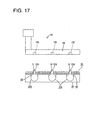
- the alignment plate 50 is assembled up to proper depth, the respective connector(s) 22A is/are supported in (the) proper posture(s) by being passed through the corresponding insertion hole(s) 51 as shown in FIGS. 17 and 18. Thereafter, when the intermediate connector 10 is assembled, the respective connector portion(s) 22A substantially aligned in advance is/are smoothly fitted into the corresponding valve fitting portion(s) 15A as shown in FIGS. 19 and 20.
- the construction can be simplified because no special construction is necessary to position the solenoid valves 20A and the intermediate connector 10 with respect to each other.
- FIGS. 21 to 30 A third preferred embodiment of the present invention is described with reference to FIGS. 21 to 30.
- the intermediate connector 10 and the valve body 30 are provided with one or more positioning means. It should be noted that no repeated description is given on the similar or same construction as the first embodiment by identifying them by the same reference numerals.
- one or more, preferably a pair of (preferably substantially cylindrical) positioning pins 18 project down or towards the valve body 30 at (preferably substantially opposite) end position(s) of the switchboard 14 of the intermediate connector 10 with respect to X-direction.
- a tapered or converging or rounded surface 18a tapered or converging or rounded toward the leading end is formed at least partly around the outer circumferential surface of a leading end portion of each positioning pin 18.
- valve fitting portions 15B corresponding to the respective solenoid valve(s) 20 are formed preferably substantially side by side in the switchboard 14, wherein the respective valve fitting portion(s) 15B is/are formed by recessing the lower surface of the switchboard 14.
- a (preferably substantially L-shaped) guiding portion 19 when viewed from below projects from the peripheral edge of each valve fitting portion 15B at the lower surface of the switchboard 14.
- Each guiding portion 19 includes a lateral plate portion 19a (first portion) extending substantially along X-direction and a longitudinal plate portion 19b (second portion) extending substantially along Y-direction (or in a direction at an angle different from 0° or 180°, preferably substantially normal to the first portion 19a), the lateral and longitudinal plate portions 19a, 19b being coupled to each other, and the inner surface of the guiding portion 19 preferably is substantially in flush with the inner circumferential surface of the valve fitting portion 15B.
- the lateral plate portion 19a of the guiding portion 19 can be brought into contact with an outer surface 22Ba of a connector portion 22B, the outer surface 22Ba extending substantially along X-direction, whereas the longitudinal plate portion 19b of the guiding portion 19 can be brought into contact with an outer surface 22Bb of the connector portion 22B, the outer surface 22Bb extending substantially along Y-direction (or in a direction at an angle different from 0° or 180°, preferably substantially normal to the outer surface 22Ba).
- the lateral and longitudinal plate portions 19a, 19b preferably are formed to be longer than corresponding sides of the valve fitting portion 15B.
- each positioning groove 32 preferably is substantially L-shaped when viewed from above and includes a lateral portion 32a extending substantially along X-direction and a longitudinal portion 32b extending substantially along Y-direction (or in a direction at an angle different from 0° or 180°, preferably substantially normal to the lateral portion 32a), the lateral and longitudinal portions 32a, 32b being coupled to each other.
- FIG. 22 is a starting position and a front end of the longitudinal portion 32b in FIG. 22 is a final position.
- the connector portions 22B of the respective solenoid valves 20B are pushed by the corresponding guiding portions 19 to substantially align the respective connector portions 22B with the corresponding valve fitting portion 15B.
- the connector portions 22B are distanced from or in contact with the longitudinal plate portions 19b even if the connector portions 22B are maximally inclined to left in FIG. 22 (toward the longitudinal portions 19b), and they are distanced from or in contact with the lateral portions 19a even if the connector portions 22B are maximally retracted backward (toward the lateral plate portions 19a).
- the connector portion(s) 22B of the respective solenoid valve(s) 20B is/are inclined to left (toward the longitudinal plate portions 19b) in FIG. 22 substantially along X-direction while being retracted backward in FIG. 22 (toward the lateral plate portions 19a) substantially along Y-direction.
- the intermediate connector 10 is assembled and the respective positioning pins 18 are at least partly inserted at the starting positions in the lateral portions 32a of the corresponding positioning grooves 32.
- the switchboard 14 is operated along X- and/or Y-directions so that the positioning pin(s) 18 move(s) substantially along the positioning groove(s) 32, while being held at such a height that the respective connector portion(s) 22B is/are distanced from the valve fitting portion(s) 15B.
- the one or more outer surfaces 22Bb of the connector portions 22B extending substantially along Y-direction are pushed by the longitudinal plate portions 19b, whereby the solenoid valves 20B turn or rotate about their longitudinal axes relative to the brackets 40 to correct the postures thereof with respect to X-direction to those fittable into the valve fitting portions 15B as shown in FIG. 27.
Abstract
Description
- The present invention relates to a construction and a method for connecting an intermediate connector and one or more electrical components.
- A plurality of solenoid valves for hydraulic control are provided in a device in a casing, for example, in an automatic transmission of an automotive vehicle, and an intermediate connector for connecting these solenoid valves with an external circuitry is so provided as to penetrate the casing from the inside to the outside. An internal connector is fitted in a fitting portion inside the intermediate connector, and a plurality of connectors are provided at ends of wires drawn out from the internal connector and are connected with connector portions of the respective solenoid valves. One example of such a connecting construction is known from Japanese Unexamined Patent Publication No. H06-223903.
- Since the respective connectors need to be individually connected with the corresponding solenoid valves in the above connecting construction, there has been a problem of poor operability due to a larger number of operation steps.
- The present invention was developed in view of the above problem, and an object thereof is to improve operability.
- This object is solved according to the invention by the features of the independent claims. Preferred embodiments of the invention are subject of the dependent claims.
- According to the invention, there is provided a construction for connecting one or more electrical components arranged in or on a casing and an intermediate connector to be electrically connected with an external circuitry, comprising:
- one or more electrical-component fitting portions which are integrally or unitarily provided in the intermediate connector and into which connector portions provided on the respective electrical components are to be at least partly fitted at once as the intermediate connector is assembled,
- at least one aligning means provided at least in or for either the electrical-component fitting portions or the electrical components for aligning the electrical-component fitting portions and the electrical components by displacing them relative to each other in a direction at an angle different from 0° or 180°, preferably substantially normal to a fitting direction, and
- at least one positioning means for positioning the electrical-component fitting portions and/or the electrical components provided with the aligning means in such postures fittable or insertable to the mating sides.
-
- When the intermediate connector is assembled, the one or more connector portions of the respective electrical components is/are at least partly fitted into the respective electrical-component fitting portions at once and the respective electrical component(s) is/are connected with the external circuitry via the intermediate connector. Accordingly, operability can be improved as compared to a case where the respective electrical components are individually connected as in the prior art. Further, at the time of the assembling, the electrical-component fitting portions and/or the electrical components provided with the aligning means are positioned in such postures fittable or insertable to the mating sides by the positioning means, and the electrical-component fitting portions and the electrical components are fitted to or connected with each other while being substantially aligned by the aligning means. Thus, the fitting operation can be smoothly carried out and, as a result, connection operability becomes better.
- According to a preferred embodiment of the invention, there is provided a construction for connecting a plurality of electrical components arranged in a casing and an intermediate connector electrically connected with an external circuitry, comprising:
- a plurality of electrical-component fitting portions which are integrally provided in the intermediate connector and into which connector portions provided on the respective electrical components are fitted at once as the intermediate connector is assembled,
- an aligning means provided at least in or for either the electrical-component fitting portions or the electrical components for aligning the electrical-component fitting portions and the electrical components by displacing them relative to each other in a direction substantially normal to a fitting direction, and
- a positioning means for positioning the electrical-component fitting portions and/or the electrical components provided with the aligning means in such postures fittable to the mating sides.
-
- Preferably, the respective electrical components are to be mounted in a device to be placed in the casing, and
the positioning means comprises: - at least one first positioning pin provided on either one of the intermediate connector and the device,
- at least one first positioning recess formed in the other of the intermediate connector and the device and capable of at least partly receiving the first positioning pin as the intermediate connector is assembled.
-
- Further preferably, the positioning means comprises:
- one or more second positioning pins provided on either the electrical-component fitting portions or the electrical component(s), and
- one or more second positioning recesses formed in the others of the electrical-component fitting portion(s) and the electrical component(s) and capable of receiving the respective second positioning pin(s) as the intermediate connector is assembled.
-
- Most preferably, the respective electrical components are mounted in a device placed in the casing, and
the positioning means comprises: - a first positioning pin provided on either one of the intermediate connector and the device,
- a first positioning recess formed in the other of the intermediate connector and the device and capable of receiving the first positioning pin as the intermediate connector is assembled,
- second positioning pins provided on either the electrical-component fitting portions or the electrical components, and
- second positioning recesses formed in the others of the electrical-component fitting portions and the electrical components and capable of receiving the second positioning pins as the intermediate connector is assembled.
-
- When the intermediate connector is assembled, the first positioning pin is first inserted into the first positioning recess, thereby positioning the intermediate connector and the device. Subsequently, the second positioning pins are inserted into the second positioning recesses, whereby the electrical-component fitting portions and the connector portions are aligned with each other by the aligning means while being positioned. Thus, the fitting operation can be smoothly carried out.
- According to a further preferred embodiment of the invention, each electrical component comprises the aligning means, and
the positioning means comprises an alignment plate to be assembled before the intermediate connector, wherein the alignment plate is formed with one or more insertion holes through which the respective connector portion(s) is/are passed and which can support the connector portion(s) in such posture(s) at least partly fittable into the electrical-component fitting portion(s). - Preferably, the positioning means further comprises one or more guiding surfaces capable of guiding the passage of the respective connector portions through the insertion holes by being brought substantially into sliding contact with the respective connector portions at the time of the assembling are formed on at least part of the peripheral edges of the insertion holes.
- Most preferably, each electrical component comprises the aligning means, and
the positioning means comprises an alignment plate to be assembled before the intermediate connector, wherein the alignment plate is formed with insertion holes through which the respective connector portions are passed and which can support the connector portions in such postures fittable into the electrical-component fitting portions, and guiding surfaces capable of guiding the passage of the respective connector portions through the insertion holes by being brought into sliding contact with the respective connector portions at the time of the assembling are formed on the peripheral edges of the insertion holes. - When the alignment plate is first assembled, the respective connector portions are guided by the guiding surfaces, thereby being passed through the insertion holes while being aligned by the aligning means to take such postures fittable into the electrical-component fitting portions. Thus, the connector portions are supported in the above postures. Thereafter, by assembling the intermediate connector, the respective connector portions aligned in advance are smoothly fitted into the corresponding electrical-component fitting portions. According to the present invention, it is not necessary to provide the electrical components and the intermediate connector with any special construction for positioning.
- According to a further preferred embodiment of the invention, the respective electrical components are to be mounted in a device placed in the casing and each electrical component includes the aligning means, and
the positioning means comprises: - at least one positioning pin provided on either one of the intermediate connector and the device,
- at least one positioning groove which is formed in the other of the intermediate connector and the device and into which the positioning pin is at least partly insertable at the time of the assembling.
-
- Preferably, the positioning means comprises one or more guiding portions capable of guiding the respective connector portions to such postures at least partly fittable into the electrical-component fitting portions by pressing outer surfaces of the respective connector portions as the positioning pin is moved along the positioning groove in a direction at an angle different from 0° or 180°, preferably substantially normal to an assembling direction.
- Most preferably, the respective electrical components are mounted in a device placed in the casing and each electrical component includes the aligning means, and
the positioning means comprises: - a positioning pin provided on either one of the intermediate connector and the device,
- a positioning groove which is formed in the other of the intermediate connector and the device and into which the positioning pin is insertable at the time of the assembling, and guiding portions capable of guiding the respective connector portions to such postures fittable into the electrical-component fitting portions by pressing outer surfaces of the respective connector portions as the positioning pin is moved along the positioning groove in a direction substantially normal to an assembling direction.
-
- According to the invention, there is further provided a method for connecting one or more electrical components arranged in or on a casing and an intermediate connector to be electrically connected with an external circuitry, in particular using a construction according to the invention or a preferred embodiment thereof, comprising the following steps:
- integrally or unitarily providing in the intermediate connector one or more electrical-component fitting portions into which connector portions provided on the respective electrical components are to be at least partly fitted at once as the intermediate connector is assembled,
- aligning the electrical-component fitting portions and the electrical components by means of an aligning means provided at least in or for either the electrical-component fitting portions or the electrical components by displacing the electrical-component fitting portions and the electrical components relative to each other in a direction at an angle different from 0° or 180°, preferably substantially normal to a fitting direction, and
- positioning the electrical-component fitting portions and/or the electrical components provided with the aligning means in such postures fittable to the mating sides by means of a positioning means.
-
- According to a preferred embodiment of the invention, the respective electrical components are mounted in a device to be placed in the casing, and
the positioning means comprises: - at least one first positioning pin provided on either one of the intermediate connector and the device, at least one first positioning recess formed in the other of the intermediate connector and the device and capable of at least partly receiving the first positioning pin as the intermediate connector is assembled and/or
- one or more second positioning pins provided on either the electrical-component fitting portions or the electrical component(s), and
- one or more second positioning recesses formed in the others of the electrical-component fitting portion(s) and the electrical component(s) and capable of receiving the respective second positioning pin(s) as the intermediate connector is assembled.
-
- Preferably, each electrical component comprises the aligning means, and
the positioning means comprises an alignment plate which is assembled before the intermediate connector, wherein the alignment plate is formed with one or more insertion holes through which the respective connector portion(s) is/are passed and which can support the connector portion(s) in such posture(s) at least partly fittable into the electrical-component fitting portion(s), wherein the positioning means preferably further comprises one or more guiding surfaces capable of guiding the passage of the respective connector portions through the insertion holes by being brought substantially into sliding contact with the respective connector portions at the time of the assembling are formed on at least part of the peripheral edges of the insertion holes. - Further preferably, the respective electrical components are mounted in a device placed in the casing and each electrical component includes the aligning means, and
the positioning means comprises: - at least one positioning pin provided on either one of the intermediate connector and the device,
- at least one positioning groove which is formed in the other of the intermediate connector and the device and into which the positioning pin is at least partly insertable at the time of the assembling wherein the positioning means preferably further comprises one or more guiding portions capable of guiding the respective connector portions to such postures at least partly fittable into the electrical-component fitting portions by pressing outer surfaces of the respective connector portions as the positioning pin is moved along the positioning groove in a direction at an angle different from 0° or 180°, preferably substantially normal to an assembling direction.
-
- These and other objects, features and advantages of the present invention will become more apparent upon reading of the following detailed description of preferred embodiments and accompanying drawings. It should be understood that even though embodiments are separately described, single features thereof may be combined to additional embodiments.
- FIG. 1 is a bottom view of an intermediate connector according to a first embodiment of the invention,
- FIG. 2 is a plan view of a valve body and solenoid valves,
- FIG. 3 is a front view partly in section showing a state before the intermediate connector is assembled,
- FIG. 4 is a side view partly in section showing the state before the intermediate connector is assembled,
- FIG. 5 is a front view partly in section showing a state where tapered surfaces of first positioning pins and first positioning recesses are in contact,
- FIG. 6 is a side view partly in section showing the state where the tapered surfaces of the first positioning pins and the first positioning recesses are in contact,
- FIG. 7 is a front view partly in section showing a state where tapered surfaces of second positioning pins and second positioning recesses are in contact,
- FIG. 8 is a side view partly in section showing the state where the tapered surfaces of the second positioning pins and the second positioning recesses are in contact,
- FIG. 9 is a front view partly in section showing a state where tapered surfaces of connector portions and valve fitting portions are in contact,
- FIG. 10 is a side view partly in section showing the state where the tapered surfaces of the connector portions and the valve fitting portions are in contact,
- FIG. 11 is a front view partly in section showing a state where the connector portions are properly fitted in the valve fitting portions,
- FIG. 12 is a side view partly in section showing the state where the connector portions are properly fitted in the valve fitting portions,
- FIG. 13 is a front view partly in section showing a state before an intermediate connector and an alignment plate according to a second embodiment of the invention are assembled,
- FIG. 14 is a side view partly in section showing the state before the intermediate connector and the alignment plate are assembled,
- FIG. 15 is a front view partly in section showing a state where guiding surfaces of the alignment plate are in contact with connector portions,
- FIG. 16 is a side view partly in section showing the state where the guiding surfaces of the alignment plate are in contact with the connector portions,
- FIG. 17 is a front view partly in section showing a state where the connector portions are passed through insertion holes of the alignment plate,
- FIG. 18 is a side view partly in section showing the state where the connector portions are passed through the insertion holes of the alignment plate,
- FIG. 19 is a front view partly in section showing a state where the intermediate connector is assembled,
- FIG. 20 is a side view partly in section showing the state where the intermediate connector is assembled,
- FIG. 21 is a bottom view of an intermediate connector according to a third embodiment of the invention,
- FIG. 22 is a plan view of a valve body and solenoid valves,
- FIG. 23 is a front view partly in section showing a state before the intermediate connector is assembled,
- FIG. 24 is a side view partly in section showing the state before the intermediate connector is assembled,
- FIG. 25 is a front view partly in section showing a state where positioning pins are inserted at starting positions in positioning grooves,
- FIG. 26 is a side view partly in section showing the state where the positioning pins are inserted at the starting positions in the positioning grooves,
- FIG. 27 is a front view partly in section showing a state where the positioning pins are located at middle positions of the positioning grooves,
- FIG. 28 is a side view partly in section showing the state where the positioning pins are located at the middle positions of the positioning grooves,
- FIG. 29 is a front view partly in section showing a state where the intermediate connector is assembled, and
- FIG. 30 is a side view partly in section showing the state where the intermediate connector is assembled.
-
- A first preferred embodiment of the present invention is described with reference to FIGS. 1 to 12. In this first embodiment, one or more, preferably a plurality of (two)
solenoid valves 20 for hydraulic or pneumatic control are mounted in avalve body 30 placed in a casing C e.g. of an automatic transmission of an automotive vehicle, and are to be electrically connected with an external circuitry via anintermediate connector 10. In the following description, reference is made to FIGS. 3 and 4 concerning vertical direction VD while being made to directions of arrows X, Y in FIG. 1 concerning horizontal direction. - As shown in FIGS. 1, 3 and 4, the
intermediate connector 10 includes aconnector housing 11 made e.g. of a synthetic resin and having one or more, preferably a plurality of busbars arranged or embedded therein or thereon, and a part of thisconnector housing 11 to be mounted through an opening H formed in one surface of the casing C serves as an external-circuitry fitting orconnection portion 12 connectable with an external connector (not shown) connected with the outer circuitry. A (preferably substantially laterally long)switchboard 14 is to be coupled to this external-circuitryfitting portion 12 by way of a (preferably substantially vertically extending)coupling portion 13, and is integrally or unitarily provided with one or more, e.g. two valvefitting portions 15 connectable with thesolenoid valves 20 and preferably extending side by side substantially along X-direction. Eachvalve fitting portion 15 preferably is substantially in the form of a rectangular tube projecting down (or towards the valve body 30) from the lower or facing surface of theswitchboard 14, and a tapered or converging or roundedsurface 15a is formed at least partly around the inner circumferential edge at the leading end thereof so as to guide a connecting operation of aconnector portion 22. Bottom or distal ends of the busbars at least partly project into thevalve fitting portion 15 and serve as connectingportions 15b with thesolenoid valve 20. Two connectingportions 15b are arranged substantially side by side substantially along X-direction in eachvalve fitting portion 15. Upper or distal ends of the two connectingportions 15b are arranged in the external-circuitryfitting portion 12 for electrical connection with terminals of the external connector. Aseal ring 12a for sealing up the opening H by being held in close contact with the inner circumferential surface of the opening H is mounted or mountable on the outer circumferential surface of the external-circuitryfitting portion 12. - As shown in FIGS. 2 to 4, each
solenoid valve 20 includes a substantially cylindricalmain portion 21 having a coil (not shown) or the like inside, and is to be mounted by means of abracket 40 with one end of themain portion 21 inserted through a side surface of the box-shapedvalve body 30, so that a hydraulic pressure in a hydraulic path in thevalve body 30 can be controlled or supplied. Twosolenoid valves 20 are arranged substantially side by side substantially along X-direction. The substantially block-shapedconnector portion 22 rectangular when viewed from above projects upward or outward at a part of themain portion 21 projecting out from thevalve body 30, and atapered surface 22a is formed around the outer circumferential edge of the leading end of thisconnector portion 22 in order to guide the mating movement of theconnector portion 22 into thevalve fitting portion 15. One or more, preferably a pair ofterminal fittings 23 connected or connectable with lead wires of coils are at least partly accommodated preferably substantially side by side in theconnector portion 22. One or moreresilient contact pieces 23a of theterminal fittings 23 can be resiliently brought into contact with the connectingportions 15b of theintermediate connector 10. A mating direction MD of theconnector portion 22 and thevalve fitting portion 15 preferably extends along vertical direction VD, and preferably is the same direction in which theintermediate connector 10 is assembled with thevalve body 30. - Each
solenoid valve 20 is so mounted as to be displaceable relative to thecorresponding bracket 40 along horizontal direction in the shown example (direction at an angle different from 0° or 180°, preferably substantially normal to the mating direction MD), thereby being able to be aligned with the matingvalve fitting portion 15. In other words, thesolenoid 20 is provided with an aligning means. More specifically, themain portion 21 of thesolenoid valve 20 is provided with a small-diameter portion 24 having a diameter smaller than the leading end of themain portion 21 where theconnector portion 22 is provided, and thebracket 40 is mounted or mountable on this small-diameter portion 24. Thebracket 40 preferably is substantially L-shaped as a whole, and the leading end of a vertical part 41 (or a part substantially parallel to the mating direction MD) at least partly fittable to the small-diameter portion 24 has a substantially annular shape extending along the outer circumferential surface of the small-diameter portion 24, so that themain portion 21 is rotatable or pivotable about its longitudinal axis relative to thevertical portion 41. Thus, theconnector portion 22 is displaceable along X-direction relative to thevalve fitting portion 15. A rotatable range of themain portion 21 can be restricted by unillustrated stoppers and can be, for example, restricted to an angle range of about 5° to left and right from a posture where theconnector portion 22 is substantially vertical or aligned. On the other hand, the small-diameter portion 24 of themain portion 21 slides in contact with thevertical part 41 of thebracket 40, whereby themain portion 21 is slidable substantially along longitudinal direction (Y-direction) relative to thevertical part 41. Thus, theconnector portion 22 is displaceable along Y-direction relative to thevalve fitting portion 15. Further, ahorizontal part 42 of thebracket 40 is to be fixed to thevalve body 30 by means of a screw or the like. - The
intermediate connector 10, thesolenoid valve 20 and thevalve body 30 are provided with one or more positioning means for positioning thesolenoid valves 20 in such postures fittable into the valvefitting portions 15. More specifically, one or more, preferably a pair of substantially cylindrical first positioning pins 16 are so provided at (preferably substantially opposite) end position(s) of theswitchboard 14 of theintermediate connector 10 with respect to X-direction as to project more downward than the valvefitting portions 15. A tapered or converging or roundedsurface 16a is formed at least partly around the outer circumferential surface of a leading end portion of eachfirst positioning pin 16 to be tapered or converging or rounded toward the leading end. On the other hand, a corresponding number of, preferably a pair of first positioning recesses 31 capable of at least partly receiving the respective first positioning pin(s) 16 are formed at (preferably substantially opposite) end position(s) of the upper or facing surface of thevalve body 30 with respect to X-direction. Eachfirst positioning recess 31 preferably is substantially rectangular when viewed from above, and a tapered or converging or roundedsurface 31a tapered or converging or rounded toward the inner side so that a receiving opening of therecess 31 is wider toward the leading end is formed around the inner circumferential surface of a leading end portion of therecess 31. In the process of assembling theintermediate connector 10 with thevalve body 30, the first positioning pins 16 are at least partly inserted into the first positioning recesses 31 to bring the outer and inner circumferential surfaces of thepins 16 and therecesses 31 into sliding contact, whereby theintermediate connector 10 can be positioned along X-direction and Y-direction with respect to thevalve body 30. - At least one
second positioning pin 25 projecting more upward or outward than theconnector portion 22 is provided at the (preferably other) end of themain portion 21 of eachsolenoid valve 20. Thesecond positioning pin 25 preferably is substantially cylindrical and has such a height as to project more upward or outward than theconnector portion 22. A tapered or converging or roundedsurface 25a is so formed at least partly around the outer circumferential surface of a leading end portion of thesecond positioning pin 25 as to be tapered or converging or rounded toward the leading end. Thesecond positioning pin 25 is coupled to or provided on a side surface of theconnector portion 22 preferably via acoupling portion 26. On the other hand, one or more, preferably a pair of projecting portions projecting the substantially same distance as the valvefitting portions 15 and coupled to or provided on (the side surfaces of) theswitchboard 14 are provided on theswitchboard 14 of theintermediate connector 10, and one or more second positioning recesses 17 capable of at least partly receiving the second positioning pin(s) 25 are formed in these projecting portions. Eachsecond positioning recess 17 preferably is substantially rectangular when viewed from below, and a tapered or converging or roundedsurface 17a tapered or converging or rounded to make a receiving opening of therecess 17 wider toward the leading end is formed at least partly around the inner circumferential surface of a leading end portion of therecess 17. Peripheral portion(s) of the second positioning recesses 17 and the valvefitting portions 15 is/are formed to communicate with each other so that thecoupling portions 26 are at least partly insertable. In the process of assembling theintermediate connector 10 with thevalve body 30, the second positioning pins 25 are at least partly inserted into the second positioning recesses 17 to bring the outer and inner circumferential surfaces thereof substantially into sliding contact before theconnector portions 22 are at least partly fitted into the valvefitting portions 15, whereby the connector positions 22 are displaced along X- and/or Y-directions by the aligning means to have the postures thereof so corrected as to be at least partly fittable or insertable into the valvefitting portions 15. - Next, functions of this embodiment constructed as above are described. After the one or more, preferably both
solenoid valves 20 are mounted into thevalve body 30, theintermediate connector 10 is assembled. As theintermediate connector 10 is lowered toward thevalve body 30, the first positioning pin(s) 16 is/are first at least partly inserted into the corresponding first positioning recess(es) 31. At this time, even if theintermediate connector 10 and thevalve body 30 are displaced along X-and/or Y-directions relative to each other, thetapered surfaces - As the assembling further proceeds, the second positioning pin(s) 25 is/are at least partly inserted into the respective second positioning recess(es) 17 before the connector portion(s) 22 is/are at least partly fitted into the respective valve fitting portion(s) 15. At this time, even if the connector portion(s) 22 is/are displaced along X-and/or Y-directions relative to the corresponding valve fitting portion(s) 15, for example, because the mount positions of the
respective solenoid 22 in thevalve body 30 are displaced from proper ones or the positions of theconnector portions 22 relative to thecorresponding brackets 40 are displaced from substantially proper ones about their longitudinal axes and/or along longitudinal direction, the tapered or converging orrounded surfaces - Since the connector portion(s) 22 and the valve fitting portion(s) 15 is/are aligned in this way, the connector portion(s) 22 is/are smoothly at least partly fitted into the valve fitting portion(s) 15 as the assembling proceeds. At this time, as shown in FIGS. 9 and 10, the fitting operation is made smoother by the sliding contact of the
tapered surfaces fitting portion 12 of theintermediate connector 10 is mounted through the opening H of the casing C, and the external connector is at least partly fitted or inserted into the external-circuitryfitting portion 12 to electrically connect the (both) solenoid valve(s) 20 with the external circuitry. - As described above, according to this embodiment, the connector portion(s) 22 of the (preferably both) solenoid valve(s) 20 is/are fitted at once into the corresponding valve fitting portion(s) 15 as the
intermediate connector 10 is assembled. Thus, as compared to a prior art in which connectors are individually connected with therespective solenoid valves 20, operability can be improved, for example, by reducing the number of operation steps. Further, during the assembling, the first positioning pin(s) 16 is/are at least partly inserted into the first positioning recess(es) 31 to position theintermediate connector 10 and thevalve body 30 relative to each other and, thereafter, the second positioning pin(s) 25 is/are at least partly inserted into the second positioning recess(es) 17 to align the valve fitting portion(s) 15 and the connector portion(s) 22 with each other by the turning movements of the solenoid(s) 20 about its/their longitudinal axes and/or advancing or retreating movements thereof substantially along longitudinal direction relative to the bracket(s) 40 while positioning the valve fitting portion(s) 15 and the connector portion(s) 22 with respect to each other. Thus, the fitting operation is smoothly carried out to improve operability. - Accordingly, to improve operability, one or more, preferably a plurality of
solenoid valves 20 are to be mounted in avalve body 30 to be at least partly placed in a casing C. Anintermediate connector 10 is integrally or unitarily provided with one or more respective valvefitting portions 15, and one ormore connector portions 22 of therespective solenoid valves 20 are at least partly fittable or insertable into the valve fitting portion(s) 15 at once as the intermediate connector is assembled. Thesolenoid valves 20 are so mounted as to be displaceable substantially along horizontal direction relative to one ormore brackets 40 fixed to thevalve body 30. At the time of the assembling, one or more first positioning pins 16 provided on theintermediate connector 10 are at least partly inserted into one or more first positioning recesses 31 formed in thevalve body 30 and one or more second positioning pins 25 provided on the connector portion(s) 22 are at least partly inserted into one or more respective second positioning recesses 17 formed in the valvefitting portions 15, whereby theconnector portions 22 are positioned in such postures at least partly fittable or insertable into the valvefitting portions 15. - A second preferred embodiment of the present invention is described with reference to FIGS. 13 to 20. In the second embodiment, instead of the respective positioning pins and the respective positioning recesses of the first embodiment, an
alignment plate 50 separate from theintermediate connector 10 is used as a preferred positioning means. In the second embodiment, no repeated description is given on the similar or same construction as the first embodiment by identifying them by the same reference numerals. Further, the casing and other members are not shown in the second embodiment. - As shown in FIG. 13, one or more, e.g. three
solenoid valves 20A are to be mounted preferably substantially side by side at or on a side surface of thevalve body 30. Three valvefitting portions 15A are so formed in theswitchboard 14 of theintermediate connector 10 as to substantially correspond to therespective solenoid valves 20A. The respective valve fitting portion(s) 15A is/are formed by recessing the lateral (lower) surface of theswitchboard 14. - The
alignment plate 50 is made e.g. of a synthetic resin and in the form of a plate to be arranged substantially parallel with theswitchboard 14. A corresponding number of (e.g. three) insertion holes 51 for permitting the passage of respective connector portion(s) 22A of therespective solenoids 20A are formed in thealignment plate 50. The connector portion(s) 22A is/are passed through this/these insertion hole(s) 51, thereby being supported in such postures at least partly fittable into the valvefitting portions 15A. The respective insertion hole(s) 51 vertically penetrate(s) thealignment plate 50, and respective guiding surface(s) 52 widened toward receiving openings for theconnector portions 22A are at least partly circumferentially formed at the bottom ends of the insertion hole(s) 51. The passage of theconnector portions 22A through the insertion holes 51 can be guided by these guiding surfaces 52. - Next, an assembling operation is described. Prior to the assembling of the
intermediate connector 10, thealignment plate 50 is assembled. Here, even if the connector portion(s) 22A is/are displaced along X- and/or Y-directions relative to the corresponding valve fitting portion(s) 15A, for example, because the mount positions of the respective valve solenoid 20A relative to the valve body 30 are displaced from proper ones and/or the positions of the connector portion(s) 22A relative to the corresponding bracket(s) 40 is/are displaced from proper one(s) about its/their longitudinal axes and/or along longitudinal direction, the leading end portion(s) of the respective connector portion(s) 22A is/are brought substantially into sliding contact with the guiding surface(s) 52 of the corresponding insertion hole(s) 51 of the alignment plate 50 as shown in FIGS. 15 and 16, whereby the solenoid valve(s) 20A turn(s) about its/their longitudinal axis/axes and/or advance(s) or retreat(s) along longitudinal direction relative to the bracket(s) 40 to correct the posture(s) of the connector portion(s) 22A to (the) proper one(s) so that the connector portion(s) 22A can be at least partly fitted into the valve fitting portion(s) 15A. When thealignment plate 50 is assembled up to proper depth, the respective connector(s) 22A is/are supported in (the) proper posture(s) by being passed through the corresponding insertion hole(s) 51 as shown in FIGS. 17 and 18. Thereafter, when theintermediate connector 10 is assembled, the respective connector portion(s) 22A substantially aligned in advance is/are smoothly fitted into the corresponding valve fitting portion(s) 15A as shown in FIGS. 19 and 20. - According to this embodiment described as above, the construction can be simplified because no special construction is necessary to position the
solenoid valves 20A and theintermediate connector 10 with respect to each other. - A third preferred embodiment of the present invention is described with reference to FIGS. 21 to 30. In the third embodiment, instead of the alignment plate shown in the second embodiment, the
intermediate connector 10 and thevalve body 30 are provided with one or more positioning means. It should be noted that no repeated description is given on the similar or same construction as the first embodiment by identifying them by the same reference numerals. - As shown in FIGS. 21, 23 and 24, one or more, preferably a pair of (preferably substantially cylindrical) positioning pins 18 project down or towards the
valve body 30 at (preferably substantially opposite) end position(s) of theswitchboard 14 of theintermediate connector 10 with respect to X-direction. A tapered or converging or roundedsurface 18a tapered or converging or rounded toward the leading end is formed at least partly around the outer circumferential surface of a leading end portion of eachpositioning pin 18. On the other hand, similar to the second embodiment, one or more, e.g. threevalve fitting portions 15B corresponding to the respective solenoid valve(s) 20 are formed preferably substantially side by side in theswitchboard 14, wherein the respective valve fitting portion(s) 15B is/are formed by recessing the lower surface of theswitchboard 14. A (preferably substantially L-shaped) guidingportion 19 when viewed from below projects from the peripheral edge of each valvefitting portion 15B at the lower surface of theswitchboard 14. Each guidingportion 19 includes alateral plate portion 19a (first portion) extending substantially along X-direction and alongitudinal plate portion 19b (second portion) extending substantially along Y-direction (or in a direction at an angle different from 0° or 180°, preferably substantially normal to thefirst portion 19a), the lateral andlongitudinal plate portions portion 19 preferably is substantially in flush with the inner circumferential surface of the valvefitting portion 15B. Thelateral plate portion 19a of the guidingportion 19 can be brought into contact with an outer surface 22Ba of aconnector portion 22B, the outer surface 22Ba extending substantially along X-direction, whereas thelongitudinal plate portion 19b of the guidingportion 19 can be brought into contact with an outer surface 22Bb of theconnector portion 22B, the outer surface 22Bb extending substantially along Y-direction (or in a direction at an angle different from 0° or 180°, preferably substantially normal to the outer surface 22Ba). The lateral andlongitudinal plate portions fitting portion 15B. - On the other hand, one or more, preferably a pair of
positioning grooves 32 into which the corresponding positioning pins 18 are at least partly insertable are formed in the upper surface of thevalve body 30 as shown in FIGS. 22 to 24. Each positioninggroove 32 preferably is substantially L-shaped when viewed from above and includes alateral portion 32a extending substantially along X-direction and alongitudinal portion 32b extending substantially along Y-direction (or in a direction at an angle different from 0° or 180°, preferably substantially normal to thelateral portion 32a), the lateral andlongitudinal portions positioning groove 32, a left end of thelateral portion 32a shown in FIG. 22 is a starting position and a front end of thelongitudinal portion 32b in FIG. 22 is a final position. As the inserted positioning pins 18 are moved along thepositioning grooves 32 from the starting positions towards or to the final positions, theconnector portions 22B of therespective solenoid valves 20B are pushed by the corresponding guidingportions 19 to substantially align therespective connector portions 22B with the corresponding valvefitting portion 15B. With the positioning pins 18 located at the starting positions, theconnector portions 22B are distanced from or in contact with thelongitudinal plate portions 19b even if theconnector portions 22B are maximally inclined to left in FIG. 22 (toward thelongitudinal portions 19b), and they are distanced from or in contact with thelateral portions 19a even if theconnector portions 22B are maximally retracted backward (toward thelateral plate portions 19a). - Next, the assembling operation is described. Prior to the assembling, the connector portion(s) 22B of the respective solenoid valve(s) 20B is/are inclined to left (toward the
longitudinal plate portions 19b) in FIG. 22 substantially along X-direction while being retracted backward in FIG. 22 (toward thelateral plate portions 19a) substantially along Y-direction. Thereafter, theintermediate connector 10 is assembled and the respective positioning pins 18 are at least partly inserted at the starting positions in thelateral portions 32a of thecorresponding positioning grooves 32. Theswitchboard 14 is operated along X- and/or Y-directions so that the positioning pin(s) 18 move(s) substantially along the positioning groove(s) 32, while being held at such a height that the respective connector portion(s) 22B is/are distanced from the valve fitting portion(s) 15B. - More specifically, in the process of moving the one or more positioning pins 18 substantially along X-direction from the starting positions of the
lateral portions 32a of thepositioning grooves 32 toward middle positions, the one or more outer surfaces 22Bb of theconnector portions 22B extending substantially along Y-direction are pushed by thelongitudinal plate portions 19b, whereby thesolenoid valves 20B turn or rotate about their longitudinal axes relative to thebrackets 40 to correct the postures thereof with respect to X-direction to those fittable into the valvefitting portions 15B as shown in FIG. 27. Thereafter, in the process of moving the positioning pins 18 along Y-direction from the intermediate or middle positions to the final positions of thelongitudinal portions 32b, the outer surfaces 22Ba of theconnector portions 22B extending substantially along X-direction are pushed by thelateral plate portions 19a, whereby thesolenoid valves 20B move laterally e.g. to right in FIG. 28 (forward from the plane of FIG. 22) substantially along longitudinal direction relative to thebrackets 40 to correct the postures thereof substantially with respect to Y-direction to those fittable into the valvefitting portions 15B as shown in FIG. 28. When theintermediate connector 10 is lowered after the one or morerespective connector portions 22B are substantially aligned with the respective valvefitting portions 15B in this way, the respective connector portion(s) 22B is/are smoothly fitted into the corresponding valve fitting portion(s) 15B as shown in FIGS. 29 and 30. - As described above, since no special construction is necessary to position the
solenoid valves 20B according to this embodiment, the construction can be simplified. - The present invention is not limited to the above described and illustrated embodiments. For example, the following embodiments are also embraced by the technical scope of the present invention as defined by the claims. Beside the following embodiments, various changes can be made without departing from the scope and spirit of the present invention as defined by the claims.
- (1) In the foregoing first embodiment, the intermediate connector may be formed with the first positioning recess(es) and the valve body may be provided with the first positioning pin(s), and/or the valve fitting portion(s) may be provided with the second positioning pin(s) and the connector portion(s) may be formed with the second positioning recess(es). Similarly, the intermediate connector may be formed with the positioning groove(s) and the valve body may be provided with the positioning pin(s) in the third embodiment.
- (2) The aligning means may be, for example, such that a main body of the solenoid valve is divided into two and the respective half pieces are so assembled as to turn about the longitudinal axis and/or to advance and retreat substantially along longitudinal direction. Further, the intermediate connector may be provided with the aligning means.
- (3) The number of the solenoid valves can be arbitrarily changed, and e.g. four or more solenoid valves may be provided according to the present invention. Further, electrical components other than the solenoid valves may be provided according to the present invention.
-
-
- 10 ...
- intermediate connector
- 15, 15A, 15B...
- valve fitting portion (electrical-component fitting portion)
- 16 ..
- first positioning pin
- 17 ...
- second positioning recess
- 18 ...
- positioning pin
- 19 ...
- guiding portion
- 20, 20A, 20B...
- solenoid valve (electrical component)
- 22, 22A, 22B...
- connector portion
- 22Ba, 22Bb ...
- outer surface
- 25 ...
- second positioning pin
- 30 ...
- valve body (device)
- 31 ...
- first positioning recess
- 32 ...
- positioning groove
- 40 ...
- bracket (aligning means)
- 50 ...
- alignment plate
- 51 ...
- insertion hole
- 52 ...
- guiding surface
- C ...
- casing
Upon assembling the intermediate connector, the positioning pin is inserted into the positioning groove and moved along the positioning groove in the direction substantially normal to the assembling direction by operating the intermediate connector. At this time, the guiding portions push the outer surfaces of the respective connector portions, which are, in turn, aligned by the aligning means to take such postures fittable into the electrical-component fitting portions. Thus, the fitting operation can be smoothly carried out. According to the present invention, it is not necessary to provide the electrical components with any special construction for positioning.
wherein the positioning means comprises:
Claims (11)
- A construction for connecting one or more electrical components (20; 20A; 20B) arranged in or on a casing (C) and an intermediate connector (10) to be electrically connected with an external circuitry, comprising:one or more electrical-component fitting portions (15; 15A; 15B) which are integrally or unitarily provided in the intermediate connector (10) and into which connector portions (22; 22A; 22B) provided on the respective electrical components (20; 20A; 20B) are to be at least partly fitted at once as the intermediate connector (10) is assembled,an aligning means (40) provided at least in or for either the electrical-component fitting portions (15; 15A; 15B) or the electrical components (20; 20A; 20B) for aligning the electrical-component fitting portions (15; 15A; 15B) and the electrical components (20; 20A; 20B) by displacing them relative to each other in a direction at an angle different from 0° or 180°, preferably substantially normal to a fitting direction (MD), anda positioning means (16, 31; 17, 25; 50; 18, 32) for positioning the electrical-component fitting portions (15; 15A; 15B) and/or the electrical components (20; 20A; 20B) provided with the aligning means (40) in such postures fittable to the mating sides.
- A construction according to claim 1, wherein:the respective electrical components (20; 20A; 20B) are to be mounted in a device (30) to be placed in the casing (C), andthe positioning means (16, 31; 17, 25; 50; 18, 32) comprises:at least one first positioning pin (16) provided on either one of the intermediate connector (10) and the device (30),at least one first positioning recess (31) formed in the other of the intermediate connector (10) and the device (30) and capable of at least partly receiving the first positioning pin (16) as the intermediate connector (10) is assembled.
- A construction according to one or more of the preceding claims, wherein:the positioning means (16, 31; 17, 25; 50; 18, 32) comprises:one or more second positioning pins (25) provided on either the electrical-component fitting portions (15) or the electrical component(s) (20), andone or more second positioning recesses (17) formed in the others of the electrical-component fitting portion(s) (15) and the electrical component(s) (20) and capable of receiving the respective second positioning pin(s) (25) as the intermediate connector (10) is assembled.
- A construction according to one or more of the preceding claims, wherein:each electrical component (20B) comprises the aligning means (40), andthe positioning means (16, 31; 17, 25; 50; 18, 32) comprises an alignment plate (50) to be assembled before the intermediate connector (10), wherein the alignment plate (50) is formed with one or more insertion holes (51) through which the respective connector portion(s) (22A) is/are passed and which can support the connector portion(s) (22A) in such posture(s) at least partly fittable into the electrical-component fitting portion(s) (15A).
- A construction according to claim 4, wherein the positioning means (16, 31; 17, 25; 50; 18, 32) further comprises one or more guiding surfaces (52) capable of guiding the passage of the respective connector portions (22A) through the insertion holes (51) by being brought substantially into sliding contact with the respective connector portions (15A) at the time of the assembling are formed on at least part of the peripheral edges of the insertion holes (52).
- A construction according to one or more of the preceding claims, wherein:the respective electrical components (20B) are to be mounted in a device (30) placed in the casing (C) and each electrical component (20B) includes the aligning means (40), andthe positioning means (16, 31; 17, 25; 50; 18, 32) comprises:at least one positioning pin (18) provided on either one of the intermediate connector (10) and the device (30),at least one positioning groove (32) which is formed in the other of the intermediate connector (10) and the device (30) and into which the positioning pin (18) is at least partly insertable at the time of the assembling.
- A construction according to claim 6, wherein the positioning means (16, 31; 17, 25; 50; 18, 32) comprises one or more guiding portions (32a, 32b) capable of guiding the respective connector portions (22B) to such postures at least partly fittable into the electrical-component fitting portions (15B) by pressing outer surfaces of the respective connector portions (22B) as the positioning pin (18) is moved along the positioning groove (32) in a direction at an angle different from 0° or 180°, preferably substantially normal to an assembling direction (MD).
- A method for connecting one or more electrical components (20; 20A; 20B) arranged in or on a casing (C) and an intermediate connector (10) to be electrically connected with an external circuitry, comprising the following steps:integrally or unitarily providing in the intermediate connector (10) one or more electrical-component fitting portions (15; 15A; 15B) into which connector portions (22; 22A; 22B) provided on the respective electrical components (20; 20A; 20B) are to be at least partly fitted at once as the intermediate connector (10) is assembled,aligning the electrical-component fitting portions (15; 15A; 15B) and the electrical components (20; 20A; 20B) by means of an aligning means (40) provided at least in or for either the electrical-component fitting portions (15; 15A; 15B) or the electrical components (20; 20A; 20B) by displacing the electrical-component fitting portions (15; 15A; 15B) and the electrical components (20; 20A; 20B) relative to each other in a direction at an angle different from 0° or 180°, preferably substantially normal to a fitting direction (MD), andpositioning the electrical-component fitting portions (15; 15A; 15B) and/or the electrical components (20; 20A; 20B) provided with the aligning means (40) in such postures fittable to the mating sides by means of a positioning means (16, 31; 17, 25; 50; 18, 32).
- A method according to claim 8, wherein:wherein the positioning means (16, 31; 17, 25; 50; 18, 32) comprises:the respective electrical components (20; 20A; 20B) are mounted in a device (30) to be placed in the casing (C), andthe positioning means (16, 31; 17, 25; 50; 18, 32) comprises:at least one first positioning recess (31) formed in the other of the intermediate connector (10) and the device (30) and capable of at least partly receiving the first positioning pin (16) as the intermediate connector (10) is assembled and/orat least one first positioning pin (16) provided on either one of the intermediate connector (10) and the device (30),one or more second positioning pins (25) provided on either the electrical-component fitting portions (15) or the electrical component(s) (20), andone or more second positioning recesses (17) formed in the others of the electrical-component fitting portion(s) (15) and the electrical component(s) (20) and capable of receiving the respective second positioning pin(s) (25) as the intermediate connector (10) is assembled.
- A method according to claim 8 or 9, wherein:each electrical component (20B) comprises the aligning means (40), andthe positioning means (16, 31; 17, 25; 50; 18, 32) comprises an alignment plate (50) which is assembled before the intermediate connector (10), wherein the alignment plate (50) is formed with one or more insertion holes (51) through which the respective connector portion(s) (22A) is/are passed and which can support the connector portion(s) (22A) in such posture(s) at least partly fittable into the electrical-component fitting portion(s) (15A), wherein the positioning means (16, 31; 17, 25; 50; 18, 32) preferably further comprises one or more guiding surfaces (52) capable of guiding the passage of the respective connector portions (22A) through the insertion holes (51) by being brought substantially into sliding contact with the respective connector portions (15A) at the time of the assembling are formed on at least part of the peripheral edges of the insertion holes (52).
- A method according to claim 8, 9 or 10, wherein:wherein the positioning means (16, 31; 17, 25; 50; 18, 32) preferably further comprises one or more guiding portions (32a, 32b) capable of guiding the respective connector portions (22B) to such postures at least partly fittable into the electrical-component fitting portions (15B) by pressing outer surfaces of the respective connector portions (22B) as the positioning pin (18) is moved along the positioning groove (32) in a direction at an angle different from 0° or 180°, preferably substantially normal to an assembling direction (MD).the respective electrical components (20B) are mounted in a device (30) placed in the casing (C) and each electrical component (20B) includes the aligning means (40), andthe positioning means (16, 31; 17, 25; 50; 18, 32) comprises:at least one positioning pin (18) provided on either one of the intermediate connector (10) and the device (30),at least one positioning groove (32) which is formed in the other of the intermediate connector (10) and the device (30) and into which the positioning pin (18) is at least partly insertable at the time of the assembling
Applications Claiming Priority (2)
| Application Number | Priority Date | Filing Date | Title |
|---|---|---|---|
| JP2004181782A JP4239906B2 (en) | 2004-06-18 | 2004-06-18 | Connection structure between relay connector and electrical parts |
| JP2004181782 | 2004-06-18 |
Publications (2)
| Publication Number | Publication Date |
|---|---|
| EP1608044A1 true EP1608044A1 (en) | 2005-12-21 |
| EP1608044B1 EP1608044B1 (en) | 2010-12-29 |
Family
ID=34937525
Family Applications (1)
| Application Number | Title | Priority Date | Filing Date |
|---|---|---|---|
| EP05013142A Expired - Fee Related EP1608044B1 (en) | 2004-06-18 | 2005-06-17 | A construction and a method for connecting an intermediate connector and one or more electrical components |
Country Status (5)
| Country | Link |
|---|---|
| US (1) | US7189101B2 (en) |
| EP (1) | EP1608044B1 (en) |
| JP (1) | JP4239906B2 (en) |
| CN (1) | CN100486038C (en) |
| DE (1) | DE602005025564D1 (en) |
Cited By (1)
| Publication number | Priority date | Publication date | Assignee | Title |
|---|---|---|---|---|
| FR3030914A1 (en) * | 2014-12-23 | 2016-06-24 | Renault Sa | MULTIFUNCTIONAL BATTERY CONNECTION SYSTEM |
Families Citing this family (16)
| Publication number | Priority date | Publication date | Assignee | Title |
|---|---|---|---|---|
| WO2006136123A1 (en) * | 2005-06-23 | 2006-12-28 | Siemens Aktiengesellschaft | Electronic module |
| EP2063498B1 (en) * | 2007-11-26 | 2012-01-11 | Sumitomo Wiring Systems, Ltd. | A connector mounting structure and connector mounting method |
| US7914318B2 (en) * | 2008-11-25 | 2011-03-29 | GM Global Technology Operations LLC | Electrical connector |
| JP5355161B2 (en) * | 2009-03-16 | 2013-11-27 | アイシン・エィ・ダブリュ株式会社 | Hydraulic control device for transmission |
| JP5275133B2 (en) * | 2009-05-14 | 2013-08-28 | 矢崎総業株式会社 | Connector module |
| JP5223810B2 (en) | 2009-08-05 | 2013-06-26 | 住友電装株式会社 | Connector mounting structure |
| US10631713B2 (en) * | 2014-03-17 | 2020-04-28 | Intuitive Surgical Operations, Inc. | Multi-stage instrument connector |
| CN104332759A (en) * | 2014-11-12 | 2015-02-04 | 成都缤果科技有限公司 | Positioning mechanism for USB (Universal Serial Bus) connection |
| JP6481859B2 (en) * | 2015-08-07 | 2019-03-13 | 株式会社オートネットワーク技術研究所 | Connector fitting device |
| JP6504008B2 (en) * | 2015-09-30 | 2019-04-24 | 株式会社オートネットワーク技術研究所 | Connector fitting member and connector fitting structure |
| JP6447744B2 (en) * | 2015-11-10 | 2019-01-09 | 株式会社オートネットワーク技術研究所 | Connector device |
| US10337533B2 (en) | 2016-02-02 | 2019-07-02 | Yazaki Corporation | Connecting structure of electromagnetic valve and hydraulic pressure control device |
| JP6852600B2 (en) * | 2017-07-05 | 2021-03-31 | 株式会社オートネットワーク技術研究所 | Standby connector |
| DE102018206277A1 (en) * | 2018-04-24 | 2019-10-24 | Zf Friedrichshafen Ag | Arrangement for producing an electrical connection of an actuator |
| DE102018208608A1 (en) * | 2018-05-30 | 2019-12-05 | Robert Bosch Gmbh | Arrangement and valve |
| DE102020210547A1 (en) | 2020-08-20 | 2022-02-24 | Robert Bosch Gesellschaft mit beschränkter Haftung | Electrically operated valve |
Citations (3)
| Publication number | Priority date | Publication date | Assignee | Title |
|---|---|---|---|---|
| DE3234738A1 (en) * | 1982-09-20 | 1984-03-22 | Siemens AG, 1000 Berlin und 8000 München | Multipin plug connector |
| DE3624834A1 (en) * | 1986-07-23 | 1988-01-28 | Mafi Transport Systeme Gmbh | Centring device with automatic joining (mating) of a plug connection |
| US5919057A (en) * | 1996-06-07 | 1999-07-06 | Yazaki Corporation | Removable main connector |
Family Cites Families (9)
| Publication number | Priority date | Publication date | Assignee | Title |
|---|---|---|---|---|
| US4225206A (en) * | 1979-08-06 | 1980-09-30 | General Motors Corporation | Electrical connector for electromagnetic fuel injector |
| US4950171A (en) * | 1989-08-11 | 1990-08-21 | Itt Corporation | Fuel injector connector system |
| US4959027A (en) * | 1990-02-20 | 1990-09-25 | Itt Corporation | Fuel injector adaptor |
| JPH06223903A (en) | 1993-01-27 | 1994-08-12 | Sumitomo Wiring Syst Ltd | Wiring structure for oil filled equipment |
| JP3126849B2 (en) | 1993-05-25 | 2001-01-22 | 矢崎総業株式会社 | Rotary fitting connector |
| DE4325980C2 (en) | 1993-08-03 | 2003-06-26 | Bosch Gmbh Robert | Device for the common electrical contacting of several electrically excitable units of internal combustion engines |
| JPH08293349A (en) | 1995-04-25 | 1996-11-05 | Japan Aviation Electron Ind Ltd | Connector fitting mechanism |
| US6506069B2 (en) | 2001-01-25 | 2003-01-14 | Kelsey-Hayes Company | Floating electrical connector for a pressure sensor |
| US6875058B2 (en) * | 2002-05-31 | 2005-04-05 | Caterpillar Inc. | Electrical adapter for a fuel injector with two sets of connectors |
-
2004
- 2004-06-18 JP JP2004181782A patent/JP4239906B2/en not_active Expired - Fee Related
-
2005
- 2005-06-17 EP EP05013142A patent/EP1608044B1/en not_active Expired - Fee Related
- 2005-06-17 DE DE602005025564T patent/DE602005025564D1/en active Active
- 2005-06-20 CN CNB2005100823673A patent/CN100486038C/en not_active Expired - Fee Related
- 2005-06-20 US US11/156,749 patent/US7189101B2/en not_active Expired - Fee Related
Patent Citations (3)
| Publication number | Priority date | Publication date | Assignee | Title |
|---|---|---|---|---|
| DE3234738A1 (en) * | 1982-09-20 | 1984-03-22 | Siemens AG, 1000 Berlin und 8000 München | Multipin plug connector |
| DE3624834A1 (en) * | 1986-07-23 | 1988-01-28 | Mafi Transport Systeme Gmbh | Centring device with automatic joining (mating) of a plug connection |
| US5919057A (en) * | 1996-06-07 | 1999-07-06 | Yazaki Corporation | Removable main connector |
Cited By (2)
| Publication number | Priority date | Publication date | Assignee | Title |
|---|---|---|---|---|
| FR3030914A1 (en) * | 2014-12-23 | 2016-06-24 | Renault Sa | MULTIFUNCTIONAL BATTERY CONNECTION SYSTEM |
| WO2016102797A1 (en) * | 2014-12-23 | 2016-06-30 | Renault S.A.S. | Multifunction battery connection system |
Also Published As
| Publication number | Publication date |
|---|---|
| US7189101B2 (en) | 2007-03-13 |
| JP2006004840A (en) | 2006-01-05 |
| JP4239906B2 (en) | 2009-03-18 |
| DE602005025564D1 (en) | 2011-02-10 |
| EP1608044B1 (en) | 2010-12-29 |
| CN100486038C (en) | 2009-05-06 |
| US20050282426A1 (en) | 2005-12-22 |
| CN1710753A (en) | 2005-12-21 |
Similar Documents
| Publication | Publication Date | Title |
|---|---|---|
| EP1608044A1 (en) | A construction and a method for connecting an intermediate connector and one or more electrical components | |
| US10355414B1 (en) | Connector with a connector position assurance device | |
| US20070134957A1 (en) | Lever fitting-type connector | |
| EP1715551B1 (en) | A connector and a method of assembling it | |
| EP0794594A2 (en) | Connector and auto-parts having the connector attached thereto | |
| EP0938162A2 (en) | Two-part electrical connector | |
| US20070249206A1 (en) | Connector | |
| US8210861B2 (en) | Connector assembly having two connectors capable of movement in differing directions | |
| CN108695646B (en) | Plug connector and method for producing a plug connection | |
| CN103181033A (en) | Electrical plug element with contact lock member and test stop | |
| US20110271507A1 (en) | Connector | |
| CN103650250B (en) | Adapter and connector assembly | |
| US6971894B2 (en) | Dual action mechanical assisted connector | |
| US10090620B2 (en) | Lever-type connector having a lever with two arms with one ends of the arms joined by an operating portion and other ends joined by a coupling | |
| DE10221662A1 (en) | A lever-type connector | |
| KR20030026231A (en) | Connector with a mating assistance device | |
| CN107123886A (en) | Terminal connecting structure and electric connector | |
| EP4084233A1 (en) | Terminal position assurance and corresponding connector assembly | |
| US9905970B2 (en) | Connector with mounting member that restricts rearward movement of connector until connector is connected properly to mating connector | |
| EP1919038A1 (en) | A connector | |
| CN108352656B (en) | Connector device | |
| US10205278B2 (en) | Connector connecting device | |
| US10326232B2 (en) | Connector connecting member enabling holding-side connectors to be connected easily to device-side connectors | |
| US10333251B2 (en) | Electrical connection device | |
| CN116601510A (en) | Single contact device for a test apparatus for the conduction testing of plug connectors and test apparatus |
Legal Events
| Date | Code | Title | Description |
|---|---|---|---|
| PUAI | Public reference made under article 153(3) epc to a published international application that has entered the european phase |
Free format text: ORIGINAL CODE: 0009012 |
|
| 17P | Request for examination filed |
Effective date: 20050623 |
|
| AK | Designated contracting states |
Kind code of ref document: A1 Designated state(s): AT BE BG CH CY CZ DE DK EE ES FI FR GB GR HU IE IS IT LI LT LU MC NL PL PT RO SE SI SK TR |
|
| AX | Request for extension of the european patent |
Extension state: AL BA HR LV MK YU |
|
| AKX | Designation fees paid |
Designated state(s): DE FR |
|
| 17Q | First examination report despatched |
Effective date: 20080506 |
|
| GRAP | Despatch of communication of intention to grant a patent |
Free format text: ORIGINAL CODE: EPIDOSNIGR1 |
|
| RIN1 | Information on inventor provided before grant (corrected) |
Inventor name: FUJISAKI, RYUICHI Inventor name: MAEGAWA, AKIHITO Inventor name: NAGASHIMA, SHINYU |
|
| GRAS | Grant fee paid |
Free format text: ORIGINAL CODE: EPIDOSNIGR3 |
|
| GRAA | (expected) grant |
Free format text: ORIGINAL CODE: 0009210 |
|
| AK | Designated contracting states |
Kind code of ref document: B1 Designated state(s): DE FR |
|
| REF | Corresponds to: |
Ref document number: 602005025564 Country of ref document: DE Date of ref document: 20110210 Kind code of ref document: P |
|
| REG | Reference to a national code |
Ref country code: DE Ref legal event code: R096 Ref document number: 602005025564 Country of ref document: DE Effective date: 20110210 |
|
| PLBE | No opposition filed within time limit |
Free format text: ORIGINAL CODE: 0009261 |
|
| STAA | Information on the status of an ep patent application or granted ep patent |
Free format text: STATUS: NO OPPOSITION FILED WITHIN TIME LIMIT |
|
| 26N | No opposition filed |
Effective date: 20110930 |
|
| REG | Reference to a national code |
Ref country code: DE Ref legal event code: R097 Ref document number: 602005025564 Country of ref document: DE Effective date: 20110930 |
|
| REG | Reference to a national code |
Ref country code: FR Ref legal event code: ST Effective date: 20120229 |
|
| PG25 | Lapsed in a contracting state [announced via postgrant information from national office to epo] |
Ref country code: FR Free format text: LAPSE BECAUSE OF NON-PAYMENT OF DUE FEES Effective date: 20110630 |
|
| PGFP | Annual fee paid to national office [announced via postgrant information from national office to epo] |
Ref country code: DE Payment date: 20150609 Year of fee payment: 11 |
|
| REG | Reference to a national code |
Ref country code: DE Ref legal event code: R119 Ref document number: 602005025564 Country of ref document: DE |
|
| PG25 | Lapsed in a contracting state [announced via postgrant information from national office to epo] |
Ref country code: DE Free format text: LAPSE BECAUSE OF NON-PAYMENT OF DUE FEES Effective date: 20170103 |