EP1607948A1 - Optical information recording medium, optical information recording device, information processing device, program, and information recording method - Google Patents
Optical information recording medium, optical information recording device, information processing device, program, and information recording method Download PDFInfo
- Publication number
- EP1607948A1 EP1607948A1 EP04722685A EP04722685A EP1607948A1 EP 1607948 A1 EP1607948 A1 EP 1607948A1 EP 04722685 A EP04722685 A EP 04722685A EP 04722685 A EP04722685 A EP 04722685A EP 1607948 A1 EP1607948 A1 EP 1607948A1
- Authority
- EP
- European Patent Office
- Prior art keywords
- recording
- information
- information recording
- opc
- area
- Prior art date
- Legal status (The legal status is an assumption and is not a legal conclusion. Google has not performed a legal analysis and makes no representation as to the accuracy of the status listed.)
- Granted
Links
Images


Classifications
-
- G—PHYSICS
- G11—INFORMATION STORAGE
- G11B—INFORMATION STORAGE BASED ON RELATIVE MOVEMENT BETWEEN RECORD CARRIER AND TRANSDUCER
- G11B7/00—Recording or reproducing by optical means, e.g. recording using a thermal beam of optical radiation by modifying optical properties or the physical structure, reproducing using an optical beam at lower power by sensing optical properties; Record carriers therefor
- G11B7/007—Arrangement of the information on the record carrier, e.g. form of tracks, actual track shape, e.g. wobbled, or cross-section, e.g. v-shaped; Sequential information structures, e.g. sectoring or header formats within a track
- G11B7/00736—Auxiliary data, e.g. lead-in, lead-out, Power Calibration Area [PCA], Burst Cutting Area [BCA], control information
-
- G—PHYSICS
- G11—INFORMATION STORAGE
- G11B—INFORMATION STORAGE BASED ON RELATIVE MOVEMENT BETWEEN RECORD CARRIER AND TRANSDUCER
- G11B7/00—Recording or reproducing by optical means, e.g. recording using a thermal beam of optical radiation by modifying optical properties or the physical structure, reproducing using an optical beam at lower power by sensing optical properties; Record carriers therefor
- G11B7/12—Heads, e.g. forming of the optical beam spot or modulation of the optical beam
- G11B7/125—Optical beam sources therefor, e.g. laser control circuitry specially adapted for optical storage devices; Modulators, e.g. means for controlling the size or intensity of optical spots or optical traces
- G11B7/126—Circuits, methods or arrangements for laser control or stabilisation
- G11B7/1267—Power calibration
-
- G—PHYSICS
- G11—INFORMATION STORAGE
- G11B—INFORMATION STORAGE BASED ON RELATIVE MOVEMENT BETWEEN RECORD CARRIER AND TRANSDUCER
- G11B7/00—Recording or reproducing by optical means, e.g. recording using a thermal beam of optical radiation by modifying optical properties or the physical structure, reproducing using an optical beam at lower power by sensing optical properties; Record carriers therefor
- G11B2007/0003—Recording, reproducing or erasing systems characterised by the structure or type of the carrier
- G11B2007/0009—Recording, reproducing or erasing systems characterised by the structure or type of the carrier for carriers having data stored in three dimensions, e.g. volume storage
- G11B2007/0013—Recording, reproducing or erasing systems characterised by the structure or type of the carrier for carriers having data stored in three dimensions, e.g. volume storage for carriers having multiple discrete layers
Definitions
- the present invention relates to information recording techniques for recording information on a recordable optical information recording medium having a recording layer of a multi-layer structure.
- AV audio-visual
- CD Compact Disc
- DVD Digital Versatile Disc
- a CLV (constant linear velocity) method As a recording/reproducing method applicable to such an optical disc, there are known a CLV (constant linear velocity) method, a CAV (constant angular velocity) method and a ACLV (zone CLV) method that combines the CLV method and the CAV method.
- the CLV method an optical disc is rotated at a constant linear velocity, which gives little complexity to data management or rotation speed control since a rotation speed is constant and a linear velocity is increased as it goes to an outer side, but is capable of providing a large recording capacity.
- the CLV method it is necessary to increase a rotation speed of an optical disc as a recording point goes inner side of the optical disc, which makes it difficult to rotate the optical disc at such a high speed.
- an increase in the rotation speed of the optical disc may cause a problem of increasing motor cost, increasing sound and vibration or difficulty in servo system design.
- the CAV method rotates an optical disc at a constant angular velocity (rotation speed), which makes easy to manage data or control the rotation speed.
- a recording capacity achieved by the CAV method is smaller than that of the CLV method.
- an optical disc is divided into a plurality of zones in a radial direction so that a linear velocity is constant within each zone. Then, a rotation speed is varied so that the linear velocity is increased as it goes to outer side of the optical disc. Therefore, the ZCLV method has the advantages of both the CLV method and the CAV method.
- an optical disk drive unit performs a test write on an optical disc to record before starting recording on the optical disc. Then, the optical disk drive unit acquires an optimum recording power based on a reproduction signal characteristic obtained by reproducing information recording in a area where the test write was performed so as to perform the recording with the thus-obtained optimum recording power. Thereby, a good recording quality can be achieved.
- the acquisition of the optimum recording power based on the reproduction signal obtained from the area where the test write is performed is referred to as an OPC (optimum power control).
- the area where the test write is performed when performing the OPC may be referred to as a PCA (power calibration area).
- a multi-layer optical disc having a recording layer containing a plurality of layers instead of single layer has been developed.
- a multilayer optical disc there is known one which uses an organic dye material in addition to a reproduction only optical disc having multilayered embossed pits. Since the organic dye material reacts with light irradiation and has transparency (high optical transmittance), the organic dye material is suitable for a material of the multilayer optical disc.
- the recording of the second recording layer is performed by transmitting a light beam through the first recording layer. Therefore, an amount of the light beam reaching the second recording layer may be changed depending on a state of the first recording layer as to whether it is in a erased state (high reflectance, low transmittance) or a recorded state (low reflectance, high transmittance). Accordingly, there is a problem in that an optimum recording power acquired by OPC is changed due to changes in the amount of the light beam. Such a fluctuation in the optimum recording power may be a cause of degradation of recording characteristic such as a jitter or an error rate of the second recording layer.
- a more specific object of the present invention is to provide an optical information recording apparatus which can maintain a stable recording quality when recording information on an optical information recording medium having a recording layer of a multilayer structure according to a constant linear velocity method.
- Another object of the present invention is to provide an optical information recording apparatus which can maintain a stable recording quality when recording information on an optical information recording medium having a recording layer of a multilayer structure according to a constant angular velocity method.
- a recordable optical information recording medium of a rotating type using a laser beam and having a recording layer of a multi-layer structure having an information recording area comprising a PCA (power calibration area), which permits test writing when performing an OPC (optimum power control) process to obtain an optimum recording power of a the laser beam with respect to the each recording layer, located on each of an inner circumferential part closer to a center of rotation than the information recording area and an outer circumferential part farther from the center of rotation than the information recording area.
- PCA power calibration area
- the PCA permitting a test write when performing an OPC process is provided on each of the inner circumference part inside the information recording are of the recording layer and the outer circumference part outside the information recording area where recording of information is to be performed according to a constant angular velocity method, thereby enabling to acquire by an interpolation method an optimum recording power at an intermediate linear velocity by performing the OPC in the inner circumference part and the outer circumference part with respect to the information recording area.
- an appropriate optimum recording power can be obtained.
- an optical information recording apparatus for recording information on a recordable optical information recording medium of a rotating type, which has a plurality of recording layers each having an information recording area in which information is recorded using a laser beam, according to a constant linear velocity method
- the optical information recording apparatus comprising: OPC means for performing (optimum power control) process for acquiring an optimum recording power of the laser beam with respect to the information recording area of each of the recording layers by performing a test write on a PCA (power calibration area) provided in each of the recording layers when performing recording of information; and state determination means for determining whether the information recording area of a first one of the recording layers is in a recorded state or an erased state, the first one of the recording layers being located on a side where the laser beam is incident, wherein an OPC process is performed on the PCA of a second one of the recording layers by the OPC means after causing a state of the information recording area of the first one of the recording layers, which is determined by the state determination means, to be equal to
- an appropriate optimum recording power can be acquired under a condition the same as that when performing information recording operation.
- an optical information recording apparatus for recording information on a recordable optical information recording medium of a rotating type, which has a plurality of recording layers each having an information recording area in which information is recorded using a laser beam, according to a constant angular velocity method
- the optical information recording apparatus comprising: OPC means for performing an OPC (optical power control) process to set an optimum recording power of the laser beam to a recording power corresponding at an intermediate linear velocity that is acquired by an interpolation method using a recording power of an inner circumference part and a recording power of an outer circumference part, which are acquired by performing a test write on a PCA (power calibration area) of the inner circumference part and the outer circumference part, the inner circumference part being closer to a center of rotation of the information recording medium than the information recording area provided to each of the recording layers, the outer circumference part being farther from the center of rotation of the information recording medium than the information recording area; and state determination means for determining whether the information recording area of a first one of
- an optimum recording power can be obtained by obtaining a recording power at an intermediate linear velocity by an interpolation method using a result of the OPC in the inner circumference part and the outer circumference part with respect to the information recording area under the same condition as the information recording operation.
- an appropriate optimum recording power can be obtained even in a case where the linear velocity increases toward the outer periphery.
- an information processing apparatus for processing a plurality of kinds of information processing, comprising the above-mentioned optical information recording apparatus.
- an information processing apparatus when performing a recording operation of information according to a constant linear velocity method or a recording operation of information according to a constant angular velocity using an optical information recording medium having a recording layer of a dual layer, an information processing apparatus can be provided which can use, as a memory apparatus, an optical information recording apparatus that can obtain an optimum recording power in an OPC operation.
- a computer readable program to be installed in an optical information recording apparatus for recording information on a recordable optical information recording medium of a rotating type, which has a plurality of recording layers each having an information recording area in which information is recorded using a laser beam, according to a constant linear velocity method, the computer readable program causing the computer to perform: an OPC function for performing (optimum power control) process for acquiring an optimum recording power of the laser beam with respect to the information recording area of each of the recording layers by performing a test write on a PCA (power calibration area) provided in each of the recording layers when performing recording of information; and a state determination function for determining whether the information recording area of a first one of the recording layers is in a recorded state or an erased state, the first one of the recording layers being located on a side where the laser beam is incident, wherein the program causing the computer to perform an OPC process by the OPC function on the PCA of a second one of the recording layers after causing a state of the
- an appropriate optimum recording power can be acquired under a condition the same as that when performing information recording operation.
- a computer readable program to be installed in an optical information recording apparatus for recording information on a recordable optical information recording medium of a rotating type, which has a plurality of recording layers each having an information recording area in which information is recorded using a laser beam, according to a constant angular velocity method
- an optimum recording power can be obtained by obtaining a recording power at an intermediate linear velocity by an interpolation method using a result of the OPC in the inner circumference part and the outer circumference part with respect to the information recording area under the same condition as the information recording operation.
- an appropriate optimum recording power can be obtained even in a case where the linear velocity increases toward the outer periphery.
- an information recording method for recording information on a recordable optical information recording medium of a rotating type, which has a plurality of recording layers each having an information recording area in which information is recorded using a laser beam, according to a constant linear velocity method
- the information recording method comprising: an OPC step of performing (optimum power control) process for acquiring an optimum recording power of the laser beam with respect to the information recording area of each of the recording layers by performing a test write on a PCA (power calibration area) provided in each of the recording layers when performing recording of information; and a state determination step of determining whether the information recording area of a first one of the recording layers is in a recorded state or an erased state, the first one of the recording layers being located on a side where the laser beam is incident, wherein an OPC process is performed on the PCA of a second one of the recording layers by the OPC means after causing a state of the information recording area of the first one of the recording layers, which is determined by the state determination means, to be
- an information recording method for recording information on a recordable optical information recording medium of a rotating type, which has a plurality of recording layers each having an information recording area in which information is recorded using a laser beam, according to a constant angular velocity method
- the information recording method comprising: an OPC step of performing an OPC (optical power control) process to set an optimum recording power of the laser beam to a recording power corresponding at an intermediate linear velocity that is acquired by an interpolation method using a recording power of an inner circumference part and a recording power of an outer circumference part, which are acquired by performing a test write on a PCA (power calibration area) of the inner circumference part and the outer circumference part, the inner circumference part being closer to a center of rotation of the information recording medium than the information recording area provided to each of the recording layers, the outer circumference part being farther from the center of rotation of the information recording medium than the information recording area; and a state determination step of determining whether the information recording area of a first
- an optimum recording power can be obtained by obtaining a recording power at an intermediate linear velocity by an interpolation method using a result of the OPC in the inner circumference part and the outer circumference part with respect to the information recording area under the same condition as the information recording operation.
- an appropriate optimum recording power can be obtained even in a case where the linear velocity increases toward the outer periphery.
- An optical information recording apparatus records information on an optical disc, which is a multilayer optical disc having two record layers as a recordable rotation-type optical information recording medium.
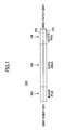
- FIG. 1 is an illustration showing an area structure of an optical disc 100 according to the first embodiment of the present invention.
- the optical disc 100 has a two-layer structure, which comprises a recording layer (first layer) 101 located on a side of an optical pickup 5 (refer to FIG. 2) mentioned later and a recording layer (second layer) 102.
- the optical disc 100 is a dye-type medium which uses an organic color dye material.
- FIG. 1 shows a cross-sectional view of the optical disc 100 taken along a radial direction.
- the optical disc 100 has an inner circumference PCA 103, an information recording area 104 and an outer PCA 105.
- the inner circumference PCA 103 is provided an inner side of the information recording area 104 so that a test write is performed during an OPC process.
- the outer PCA 105 is provided an outer side of the information recording area 104 so that a test write is performed during an OPC process. That is, the optical disc 100 according to the present embodiment has PCAs, which permit a test write during an OPC, on an inner side closer to a center of rotation than the information recording area 104 and an outer side farther from the center of rotation than the information recording area 104 in a two-layer structure.
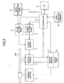
- FIG. 2 is a block diagram showing a structure of an optical disc drive apparatus 1, which records or reproduces information on or from the optical disc 100.
- the optical disc drive apparatus 1 rotates the optical disc 100 by the a rotation drive mechanism including a spindle motor 2.
- the spindle motor 2 is controlled to rotate at a constant angular velocity (rotation speed) by a motor driver 3 and a servo part 4 so that a write operation can be performed according to the CAV method or the ZCLV method.
- An optical pickup 5 is equipped with a semiconductor laser as a light source, an optical system, a focusing actuator, a tracking actuator, light-receiving actuator, a position sensor, etc. so as to project a laser beam onto a recording surface of the optical disc 100.
- the optical pickup 5 is movable in a radial direction of the disc) by a seek motor (not shown in the figure).
- the focusing actuator, the tracking actuator and the seek motor are controlled by the motor driver 3 and the servo part 4 in accordance with signals acquired from the light-receiving element and the a position sensor so that a laser spot is located at a desired target position on the optical disc 100.
- a power setting part 6 drives a laser driver 7 in accordance with a set recording power so as to drive the semiconductor laser of the optical pickup 5.
- the semiconductor laser of the optical pickup 5 is modulated between the recording power and a space power in accordance with a pulse signal input to the laser driver 7. Thereby, record marks and parts other than the record marks are formed on the recording layers of the optical disc 100.
- the pulse width set by the laser driver 7 may be fixed, the pulse width is set by the pulse setting part 8 in accordance with a linear velocity and a disc type in the present embodiment.
- the reason for setting the pulse width in accordance with a linear velocity and a disc type is to absorb a difference in sensitivity of a record mark length due to variation in the linear velocity and disc type.
- a disc type can be detected from a reproduction signal generated when information recorded in a specific area of the optical disc by the optical pickup 5. If, for example, disc manufacturers can be discriminated according to a certain method, the disc type may be classified according to each manufacture. It is better if the classification can be made further in detail within the same manufacture's discs.
- a specific manufacturer discrimination cord may be embedded in the optical disc 100 beforehand.
- a code for classification in further detail may be embedded in the optical disc 100.
- various parameters embedded in the optical disc 100 may be used. If, for example, a recommended power or pulse width is embedded, such information may be used.
- an optimum pulse width setting (write strategy) can be achieved in response to various optical discs of the same manufacture.
- a data generating part 10 When recording data, upon receipt of data transferred from a host (not shown) through an interface (I/F) 9 such as ATAPI or SCSI, a data generating part 10 applies to the data an encoding process or a modulating process in a predetermined format, and outputs the data as recording data in a serial format to the laser driver 7 through the pulse setting part 8.
- I/F interface
- a data generating part 10 applies to the data an encoding process or a modulating process in a predetermined format, and outputs the data as recording data in a serial format to the laser driver 7 through the pulse setting part 8.
- the optical disc drive apparatus 1 is equipped with a controller 11 for controlling each of the above-mentioned parts and also performing each function mentioned later.
- the controller 11 includes a microcomputer comprising a CPU (central processing unit) which controls each part, a ROM (read only memory) for storing fixed data such as a program executed by the CPU, a RAM (random access memory) for rewritably writing variable data such as work data, etc.
- a non-volatile memory 12 is connected to the controller 11.
- the controller 11 of the optical disk drive apparatus 1 performs an OPC process in the PCA of the optical disc 100 so as to acquire an optimum recording power.
- the OPC means acquisition of an optimum recording power based on a reproduction signal from an area where a test write was performed.
- a test write for a predetermined number of blocks for example, 10 blocks
- a predetermined number of blocks for example, 10 blocks
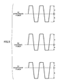
- the value P corresponding to a symmetry of an amplitude when the reproduction signal RF is AC-coupled. That is, referring to if FIG. 3 showing a state of the reproduction signal RF according to a recording power, (a) indicates an appropriate power, (b) indicates an excessive power, and (c) indicates an insufficient power.
- the lower side of the reproduction signal waveform corresponds to a part which forms record marks. Since a mark is recorded longer when a power is in excess, the duty shifts to a large even if the duty at a normal time is 50%.
- the evaluation measurement value P is represented as follows, where "a” is an upper side amplitude and "b" is a lower side amplitude that are detected by a peak and bottom detecting circuit (not shown).
- ⁇ (a-b)/(a+b) It can be appreciated from the example shown in FIG. 3 that P is substantially zero if a power is appropriate, ⁇ is increased if a power is in excess, and ⁇ is decreased if a power is insufficient.
- an optimum recording power is obtained as a recording power at which the value of P is a target value ⁇ target (for example, 0.04).
- the optical disc 100 is rotated at a constant angular velocity (rotation speed), and the test write is performed according to the CAV method or the ZCLV method.
- the optimum recording power is calculated according to the above-mentioned method, an instruction of the recording power is supplied to the laser driver 7.
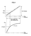
- FIG. 4 shows an example where a recording is performed while varying the power with 10 steps.
- a range of variation of the recording power is referred to as an OPC, and a central power of the range is represented by Pdef.
- the OPC range may be defined by varying within a range from +40% to -30% with respect to the Pdef with 10 steps, or may be varied with respect to the Pdef within a range from +5 mW to -4 mW by 1 mW.
- a ⁇ -curve (quadratic) is approximated in accordance with the thus-obtained 10 ⁇ values so as to acquire a power Popc corresponding to the target value ⁇ target. It is better to obtain the Popc near the Pdef under a normal condition since the Popc may somewhat fluctuate due to a condition at the time of executing the OPC process, such as a change in temperature. Moreover, since the Popc differs from an optical disc to an optical disc in many cases, the Popc may be set together with a pulse width (write strategy) corresponding to a type of an optical disc.
- a recording state of the information recording area 104 of the recording layer (first layer) 101 of the optical disc 100 is checked using management information of the optical disc 100 (step S1). If the reproduction signal RF is used, the optical pickup 5 is moved to in a radial direction from inner side to an outer side so as to acquire the reproduction signal RF. Then, position information of the optical pickup 5 and information regarding presence of the reproduction signal RF are stored.
- data in the management information recording area (not shown) is reproduced, and it is checked to what extent the information is recorded.
- step S2 After checking the recorded state of the information record area 104 of the recording layer (first layer) 101 of the optical disc 100 as mentioned above, an OPC is performed so as to acquire an optimum recording power. If information is recorded on the information record area 104 of the recording layer (first layer) 101 of the optical disc 100, (Y of step S2: state determination means), an OPC is performed on the inner circumference PCA 103 of the recording layer (first layer) 101 of the optical disc 100 (step S3: OPC means). Thereafter, an OPC is performed on the inner circumference PCA 103 of the recording layer (second layer) 102 of the optical disc 100 (step S4: OPC means).
- step S5 OPC means
- step S6 OPC means
- step S7 OPC means
- step S8 OPC means
- step S9 OPC means
- step S10 OPC means
- the reason for performing an OPC to the inner circumference PCA 103 and the outer circumference PCA 105 of the optical disc 100, respectively, is as follows.
- the optical disc 100 is rotated at a constant angular velocity (rotation speed), and a test write is performed according to the CAV method or the ZCLV method. If a recording is performed with a constant angular velocity (rotation speed), the linear velocity is increased as it goes toward an outer side. An increase in the linear velocity requires an increase in a recording power.
- an optimum recording power is acquired by performing an OPC on both an inner circumference part and an outer circumference part of the information recording area 104 of the optical disc 100.
- the reason for first performing the OPC on the recording layer (first layer) 101 of the optical disc 100, when information is recorded on the information recording area 104 of the recording layer (first layer) 101 of the optical disc 100 is as follows. That is, if information is recorded on the information recording area 104 of the recording layer (first layer) 101 of the optical disc 100, an OPC is performed on the PCA (the inner circumference PCA 103 and the outer circumference PCA 105) of the recording layer (second layer) 102 of the optical disc 100 in a state where information is written in the PCA (the inner circumference PCA 103 and the outer circumference PCA 105) of the recording layer (first layer) 101 of the optical disc 100 since the OPC is first performed on the recording layer (first layer) 101 of the optical disc 100.
- an optimum recording power is acquired in the same state where information is recorded on the information recording area 104 of the recording layer (first layer) 101 of the optical disc 100.
- the OPC is first performed on the recording layer (second layer) 102 of the optical disc 100 so that an optimum recording power is acquired in the same state where information is not recorded on the information recording area 104 of the recording layer (first layer) 101 of the optical disc 100.
- an optimum recording power can be acquired in the same state where information is recorded on the recording area.
- an optimum recording power is acquired by acquiring a recording power at an intermediate linear velocity according to an interpolation using a result of the OPC performed on the inner circumference PCA 103 and the outer circumference PCA 105. Then, the thus-acquired optimum recording power is set as the optimum recording power for the optical disc 100 (step S11), and informational recording is started (step S12).
- the optimum recording power is acquired by acquiring a recording power at an intermediate linear velocity according to an interpolation using the results of the OPC performed on the inner circumference PCA 103 and the outer circumference PCA 105 under the same condition as the information recording operation when performing information recording according to a constant angular velocity method using the optical disc 100 having a recording layer of a multilayer structure. Therefore, even in a case where the linear velocity increases as it moves toward an outer periphery, the optimum recording power can be acquired. Thereby, when performing information recording according to a constant angular velocity method using an information recording medium having a recording layer of a multilayer structure, a stable recording quality can be maintained.
- the optimum recording power, which is acquired when the OPC is performed first on the recording layer (first layer) of the optical disc 100 and the optimum recording power, which is acquired when the OPC is performed first on the recording layer (second layer) of the optical disc 100 may be stored as parameters in the non-volatile memory 12 so that the optimum recording power used can be switched in the middle of the information recording.
- An optical disc drive apparatus has basically the same structure as the optical disc drive apparatus according to the first embodiment.
- parts that are the same as the first embodiment are given the same reference numerals, and descriptions thereof will be omitted.
- the optical disc drive apparatus 1 according to the first embodiment uses the CAV method of the ZCAV method as the recording and reproducing method with respect to the optical disc 100
- the optical disc drive apparatus 1 according to the second embodiment uses the CLV method as the recording and reproducing method with respect to the optical disc 100.
- the optical disc 100 When the CLV method is used as the recording and reproducing method with respect to the optical disc 100, the optical disc 100 is rotated at a constant linear velocity, and a test write is performed according to the CLV method when performing an OPC.
- the relative velocity of the optical disc 100 and the laser beam from the semiconductor laser of the optical pickup 5 is always constant, it is not necessary to change the record conditions such as a recording power and a record pulse width over the whole surface of the optical disc if an optimum condition is once determined. For this reason, an OPC may be performed on either the inner circumference PCA 103 or the outer circumference PCA 105 of the optical disc 100, and information recording may be performed over the whole surface of the optical disc 100 at the same liner velocity using the thus-determined optimum recording power.
- a recorded state of the information recording area 104 of the recording layer (first layer) 101 of the optical disc 100 is checked using the reproduction signal RF or management information of the optical disc 100 (step S21).
- the optical pickup 5 is moved in a radial direction from an inner side to an outer side so as to acquire the reproduction signal RF, and the position information of the optical pickup 5 at this time and information regarding presence of the reproduction signal RF are stored.
- the management information of the optical disc 100 information recorded on the management information recording area (not shown) is reproduced and checks how far the information is recorded.
- an OPC is performed so as to acquire an optimum recording power.
- step S22 If information is recorded on the information record area 104 of the recording layer (first layer) 101 of the optical disc 100, (Y of step S22: state determination means), an OPC is performed on the inner circumference PCA 103 (or the outer circumference PCA 105) of the recording layer (first layer) 101 of the optical disc 100 (step S23: OPC means). Thereafter, an OPC is performed on the inner circumference PCA 103 (or the outer circumference PCA 105) of the recording layer (second layer) 102 of the optical disc 100 (step S24: OPC means).
- step S22 state determination means
- an OPC is performed on the inner circumference PCA 103 (or the outer circumference PCA 105) of the recording layer (second layer) 102 of the optical disc 100 (step S25: OPC means).
- an OPC is performed on the inner circumference PCA 103 (or the outer circumference PCA 105) of the recording layer (first layer) 101 of the optical disc 100 (step S26: OPC means).
- the reason for first performing the OPC on the recording layer (first layer) 101 of the optical disc 100, when information is recorded on the information recording area 104 of the recording layer (first layer) 101 of the optical disc 100, is as follows. That is, if information is recorded on the information recording area 104 of the recording layer (first layer) 101 of the optical disc 100, an OPC is performed on the inner circumference PCA 103 (or the outer circumference PCA 105) of the recording layer (second layer) 102 of the optical disc 100 in a state where information is written in the inner circumference PCA 103 (or the outer circumference PCA 105) of the recording layer (first layer) 101 of the optical disc 100 since the OPC is first performed on the recording layer (first layer) 101 of the optical disc 100.
- an optimum recording power is acquired in the same state where information is recorded on the information recording area 104 of the recording layer (first layer) 101 of the optical disc 100.
- the OPC is first performed on the recording layer (second layer) 102 of the optical disc 100 so that an optimum recording power is acquired in the same state where information is not recorded on the information recording area 104 of the recording layer (first layer) 101 of the optical disc 100.
- an optimum recording power can be acquired in the same state where information is recorded on the recording area.
- the thus-acquired optimum recording power is set as the optimum recording power of the optical disc 100 (step S27), and information recording is started (step S28).
- an optimum recording power can be obtained under the same condition as that when performing an information recording operation. Thereby, a stable recording quality can be maintained when performing information recording according to the constant linear velocity using the optical disc 100 having a recording layer of a multilayer structure.
- a rotation speed must be increased as a recording point goes further inner side when the CLV method is used, it may become difficult to rotate the optical disc at such a high speed.
- a motor cost may be increased so as to provided a spindle motor that can achieve a higher rotation speed, and an increase in the rotation speed may increase noise and vibration. Additionally, it may become difficult to design the servo system.
- measures may be taken to limit a decrease in the rotation speed on the outer side. That is, in such a case, the linear velocity increases toward the outer side. Therefore, as explained in the first embodiment, a result of an OPC at the outer side and a result of an OPC at the inner side are acquired so as to set a recording power at an intermediate linear velocity as an optimum recording power of the optical disc 100.
- the present invention is applied to a desk-top type personal computer 50, which is equipped with the optical disc drive apparatus 1 such as explained in the above-mentioned embodiments in addition to a 3.5-inch flexible disc drive apparatus 51.
- the optical disc drive apparatus 1 may be integrally incorporated in the personal computer 50, or may be a built-in type. Accordingly, a host is also incorporated in the personal computer 50.
- the optical disk drive apparatus 1 Since the above-mentioned optical disk drive apparatus 1 is built in the personal computer 50, the optical disk drive apparatus 1, which can acquire an optimum recording power in an OPC operation during a information recording operation according to the constant linear velocity method or the constant angular velocity method using the multilayer optical disc 100 having the two-layer recording layer, can be used as a memory apparatus of the personal computer 50.
- the optical disc drive apparatus is not limited to be built in the personal computer 50 as in the present embodiment, and may be provided alone and connected to an information processing apparatus such as an external host apparatus.
- the personal computer 50 is not limited to the desk-top type, and a portable type personal computer such as a notebook type computer may be used.
Landscapes
- Physics & Mathematics (AREA)
- Optics & Photonics (AREA)
- Optical Recording Or Reproduction (AREA)
- Optical Head (AREA)
- Optical Record Carriers And Manufacture Thereof (AREA)
Abstract
Description
Thus, instead of limiting an increase in the rotation speed on the inner side, measures may be taken to limit a decrease in the rotation speed on the outer side.
That is, in such a case, the linear velocity increases toward the outer side. Therefore, as explained in the first embodiment, a result of an OPC at the outer side and a result of an OPC at the inner side are acquired so as to set a recording power at an intermediate linear velocity as an optimum recording power of the
Claims (9)
- A recordable optical information recording medium of a rotating type using a laser beam and having a recording layer of a multi-layer structure having an information recording area, the optical information recording medium comprising a PCA (power calibration area), which permits test writing when performing an OPC (optimum power control) process to obtain an optimum recording power of a the laser beam with respect to said each recording layer, located on each of an inner circumferential part closer to a center of rotation than said information recording area and an outer circumferential part farther from the center of rotation than said information recording area.
- An optical information recording apparatus for recording information on a recordable optical information recording medium of a rotating type, which has a plurality of recording layers each having an information recording area in which information is recorded using a laser beam, according to a constant linear velocity method, said optical information recording apparatus comprising:wherein an OPC process is performed on the PCA of a second one of said recording layers by said OPC means after causing a state of the information recording area of said first one of said recording layers, which is determined by said state determination means, to be equal to a state of the PCA of said first one of said recording layers.OPC means for performing (optimum power control) process for acquiring an optimum recording power of the laser beam with respect to said information recording area of each of said recording layers by performing a test write on a PCA (power calibration area) provided in each of said recording layers when performing recording of information; andstate determination means for determining whether the information recording area of a first one of said recording layers is in a recorded state or an erased state, said first one of said recording layers being located on a side where the laser beam is incident,
- An optical information recording apparatus for recording information on a recordable optical information recording medium of a rotating type, which has a plurality of recording layers each having an information recording area in which information is recorded using a laser beam, according to a constant angular velocity method, said optical information recording apparatus comprising:wherein an OPC process by said OPC means is performed on the PCA of said inner circumference part and said outer circumference part of a second one of said recording layers after causing a state of the information recording area of a first one of said recording layers, which is determined by said state determination means, to be equal to a state of the PCA of said inner circumference part and said outer circumference part of the first one of said recording layers.OPC means for performing an OPC (optical power control) process to set an optimum recording power of the laser beam to a recording power corresponding at an intermediate linear velocity that is acquired by an interpolation method using a recording power of an inner circumference part and a recording power of an outer circumference part, which are acquired by performing a test write on a PCA (power calibration area) of the inner circumference part and the outer circumference part, the inner circumference part being closer to a center of rotation of said information recording medium than said information recording area provided to each of said recording layers, the outer circumference part being farther from the center of rotation of said information recording medium than the information recording area; andstate determination means for determining whether the information recording area of a first one of said recording layers is in a recorded state or an erased state, said first one of said recording layers being located on a side where the laser beam is incident,
- An information processing apparatus for processing a plurality of kinds of information processing, comprising:an optical information recording apparatus as claimed in claim 2.
- An information processing apparatus for processing a plurality of kinds of information processing, comprising:an optical information recording apparatus as claimed in claim 3.
- A computer readable program to be installed in an optical information recording apparatus for recording information on a recordable optical information recording medium of a rotating type, which has a plurality of recording layers each having an information recording area in which information is recorded using a laser beam, according to a constant linear velocity method, said computer readable program causing said computer to perform:wherein said program causing said computer to perform an OPC process by said OPC function on the PCA of a second one of said recording layers after causing a state of the information recording area of said first one of said recording layers, which is determined by said state determination means, to be equal to a state of the PCA of said first one of said recording layers.an OPC function for performing (optimum power control) process for acquiring an optimum recording power of the laser beam with respect to said information recording area of each of said recording layers by performing a test write on a PCA (power calibration area) provided in each of said recording layers when performing recording of information; anda state determination function for determining whether the information recording area of a first one of said recording layers is in a recorded state or an erased state, said first one of said recording layers being located on a side where the laser beam is incident,
- A computer readable program to be installed in an optical information recording apparatus for recording information on a recordable optical information recording medium of a rotating type, which has a plurality of recording layers each having an information recording area in which information is recorded using a laser beam, according to a constant angular velocity method, said computer readable program causing said computer to perform:wherein said program causing said computer to perform an OPC process by said OPC means on the PCA of said inner circumference part and said outer circumference part of a second one of said recording layers after causing a state of the information recording area of a first one of said recording layers, which is determined by said state determination means, to be equal to a state of the PCA of said inner circumference part and said outer circumference part of the first one of said recording layers.an OPC function for performing an OPC (optical power control) process to set an optimum recording power of the laser beam to a recording power corresponding at an intermediate linear velocity that is acquired by an interpolation method using a recording power of an inner circumference part and a recording power of an outer circumference part, which are acquired by performing a test write on a PCA (power calibration area) of the inner circumference part and the outer circumference part, the inner circumference part being closer to a center of rotation of said information recording medium than said information recording area provided to each of said recording layers, the outer circumference part being farther from the center of rotation of said information recording medium than the information recording area; anda state determination function for determining whether the information recording area of a first one of said recording layers is in a recorded state or an erased state, said first one of said recording layers being located on a side where the laser beam is incident,
- An information recording method for recording information on a recordable optical information recording medium of a rotating type, which has a plurality of recording layers each having an information recording area in which information is recorded using a laser beam, according to a constant linear velocity method, said information recording method comprising:wherein an OPC process is performed on the PCA of a second one of said recording layers by said OPC means after causing a state of the information recording area of said first one of said recording layers, which is determined by said state determination means, to be equal to a state of the PCA of said first one of said recording layers.an OPC step of performing (optimum power control) process for acquiring an optimum recording power of the laser beam with respect to said information recording area of each of said recording layers by performing a test write on a PCA (power calibration area) provided in each of said recording layers when performing recording of information; anda state determination step of determining whether the information recording area of a first one of said recording layers is in a recorded state or an erased state, said first one of said recording layers being located on a side where the laser beam is incident,
- An information recording method for recording information on a recordable optical information recording medium of a rotating type, which has a plurality of recording layers each having an information recording area in which information is recorded using a laser beam, according to a constant angular velocity method, said information recording method comprising:wherein an OPC process by said OPC means is performed on the PCA of said inner circumference part and said outer circumference art of a second one of said recording layers after causing a state of the information recording area of a first one of said recording layers, which is determined by said state determination means, to be equal to a state of the PCA of said inner circumference part and said outer circumference part of the first one of said recording layers.an OPC step of performing an OPC (optical power control) process to set an optimum recording power of the laser beam to a recording power corresponding at an intermediate linear velocity that is acquired by an interpolation method using a recording power of an inner circumference part and a recording power of an outer circumference part, which are acquired by performing a test write on a PCA (power calibration area) of the inner circumference part and the outer circumference part, the inner circumference part being closer to a center of rotation of said information recording medium than said information recording area provided to each of said recording layers, the outer circumference part being farther from the center of rotation of said information recording medium than the information recording area; anda state determination step of determining whether the information recording area of a first one of said recording layers is in a recorded state or an erased state, said first one of said recording layers being located on a side where the laser beam is incident,
Applications Claiming Priority (5)
| Application Number | Priority Date | Filing Date | Title |
|---|---|---|---|
| JP2003080826 | 2003-03-24 | ||
| JP2003080826 | 2003-03-24 | ||
| JP2004026683A JP2004310997A (en) | 2003-03-24 | 2004-02-03 | Optical information recording medium, optical information recorder, information processor, program and information recording method |
| JP2004026683 | 2004-02-03 | ||
| PCT/JP2004/003938 WO2004086378A1 (en) | 2003-03-24 | 2004-03-23 | Optical information recording medium, optical information recording device, information processing device, program, and information recording method |
Publications (3)
| Publication Number | Publication Date |
|---|---|
| EP1607948A1 true EP1607948A1 (en) | 2005-12-21 |
| EP1607948A4 EP1607948A4 (en) | 2008-10-08 |
| EP1607948B1 EP1607948B1 (en) | 2009-09-30 |
Family
ID=33100352
Family Applications (1)
| Application Number | Title | Priority Date | Filing Date |
|---|---|---|---|
| EP04722685A Expired - Lifetime EP1607948B1 (en) | 2003-03-24 | 2004-03-23 | Optical information recording medium, optical information recording device, information processing device, program, and information recording method |
Country Status (5)
| Country | Link |
|---|---|
| US (2) | US7304929B2 (en) |
| EP (1) | EP1607948B1 (en) |
| JP (1) | JP2004310997A (en) |
| DE (1) | DE602004023376D1 (en) |
| WO (1) | WO2004086378A1 (en) |
Cited By (1)
| Publication number | Priority date | Publication date | Assignee | Title |
|---|---|---|---|---|
| WO2006035721A1 (en) | 2004-09-28 | 2006-04-06 | Matsushita Electric Industrial Co., Ltd. | Optical disc and optical disc device |
Families Citing this family (22)
| Publication number | Priority date | Publication date | Assignee | Title |
|---|---|---|---|---|
| JP4114767B2 (en) * | 2000-10-13 | 2008-07-09 | パイオニア株式会社 | Information recording apparatus and information recording method |
| WO2004057585A1 (en) * | 2002-12-20 | 2004-07-08 | Mitsubishi Chemical Corporation | Optical recording medium, method recording optical recording medium, and recorder |
| JP2004310972A (en) * | 2003-03-25 | 2004-11-04 | Ricoh Co Ltd | Information processing device, information recording device, information processing system, information recording method, information recording program, and storage medium |
| JP3734816B2 (en) * | 2003-03-25 | 2006-01-11 | 株式会社リコー | Optical information recording apparatus, optical information recording medium, optical information recording method, program, and storage medium |
| JP2005209243A (en) * | 2004-01-20 | 2005-08-04 | Ricoh Co Ltd | Evaluation method, recording method, program, recording medium, and optical disc apparatus |
| KR100677114B1 (en) | 2004-04-27 | 2007-02-02 | 삼성전자주식회사 | Information storage medium, method and apparatus for recording / reproducing data of the information storage medium |
| JP2006040377A (en) * | 2004-07-26 | 2006-02-09 | Toshiba Corp | Optical disc, optical disc apparatus, and optical disc recording method |
| JP4263165B2 (en) * | 2004-12-09 | 2009-05-13 | 三洋電機株式会社 | Optical recording / reproducing device |
| KR20060082513A (en) * | 2005-01-12 | 2006-07-19 | 엘지전자 주식회사 | Recording medium and recording method and recording apparatus of recording medium |
| JP4445507B2 (en) * | 2005-01-14 | 2010-04-07 | パイオニア株式会社 | Recording apparatus, recording method, and computer program |
| TWI358063B (en) * | 2005-01-14 | 2012-02-11 | Pioneer Corp | Recording medium, recording apparatus and recordin |
| JP2006269038A (en) * | 2005-02-25 | 2006-10-05 | Samsung Electronics Co Ltd | Optical information recording apparatus, write strategy setting apparatus, write strategy setting method and program |
| JP2006268889A (en) * | 2005-03-22 | 2006-10-05 | Victor Co Of Japan Ltd | Optical information recording device |
| KR100688598B1 (en) * | 2005-03-25 | 2007-03-02 | 도시바삼성스토리지테크놀러지코리아 주식회사 | Method of controlling recording speed in disk drive and optical disk drive using same |
| JP2006309881A (en) * | 2005-04-28 | 2006-11-09 | Samsung Electronics Co Ltd | Optical information recording apparatus and optical information recording method |
| TWI309413B (en) * | 2005-05-17 | 2009-05-01 | Via Tech Inc | Optimum power calibration method and optical disk drive |
| KR20070003511A (en) * | 2005-06-30 | 2007-01-05 | 엘지전자 주식회사 | Recording medium and recording medium recording / reproducing method and apparatus |
| KR100657336B1 (en) * | 2005-07-13 | 2006-12-14 | 삼성전자주식회사 | Method for determining recording power of optical recording medium and optical recording and reproducing apparatus to which the method is applied |
| JP2007115341A (en) * | 2005-10-20 | 2007-05-10 | Funai Electric Co Ltd | Optical disk device and optical disk control method |
| JP2007317282A (en) * | 2006-05-24 | 2007-12-06 | Fujitsu Ltd | Storage device, self-diagnosis control device, and self-diagnosis method |
| US8400894B2 (en) * | 2010-08-25 | 2013-03-19 | Panasonic Corporation | Method for writing data on multilayer optical disc and optical disc drive |
| JP5045832B2 (en) * | 2011-03-10 | 2012-10-10 | 株式会社日立製作所 | MULTILAYER RECORDING TYPE OPTICAL DISC, MULTILAYER RECORDING TYPE OPTICAL DISC RECORDING METHOD, AND MULTILAYER RECORDING TYPE OPTICAL DISC RECORDING DEVICE |
Family Cites Families (27)
| Publication number | Priority date | Publication date | Assignee | Title |
|---|---|---|---|---|
| JP3039099B2 (en) * | 1992-02-14 | 2000-05-08 | ソニー株式会社 | Optical disk recording apparatus and method |
| US6052347A (en) * | 1996-02-23 | 2000-04-18 | Ricoh Company, Ltd. | Method and apparatus for detecting optimum recording power for an optical disk |
| JPH113550A (en) | 1997-06-12 | 1999-01-06 | Nikon Corp | Information recording / reproducing device |
| DE69938855D1 (en) * | 1998-10-21 | 2008-07-10 | Matsushita Electric Industrial Co Ltd | Optical information recording medium, method and apparatus for recording and reproduction |
| JP2002529881A (en) * | 1998-11-09 | 2002-09-10 | コーニンクレッカ フィリップス エレクトロニクス エヌ ヴィ | Method for recording on a multilayer optical recordable information carrier |
| JP3720624B2 (en) * | 1999-04-26 | 2005-11-30 | 株式会社リコー | Optical disc recording / reproducing apparatus and optimum recording power value determination method for optical disc |
| JP3720644B2 (en) * | 1999-08-06 | 2005-11-30 | 株式会社リコー | Optimal recording power value determination method and optimal recording power value determination device |
| JP2001118331A (en) * | 1999-10-19 | 2001-04-27 | Sony Corp | Recording device, recording / reproducing device, recording method |
| DE60113346T2 (en) * | 2000-07-26 | 2006-06-22 | Kabushiki Kaisha Toshiba, Kawasaki | Record carrier for information with an index start field |
| JP4114767B2 (en) * | 2000-10-13 | 2008-07-09 | パイオニア株式会社 | Information recording apparatus and information recording method |
| US20020126602A1 (en) * | 2001-01-11 | 2002-09-12 | Koninklijke Philips Electronics N.V. | Recording on a multilayer record carrier using feed forward power control |
| JP2003022532A (en) * | 2001-07-06 | 2003-01-24 | Columbia Music Entertainment Inc | Optical information recording medium and method and device for optical information recording |
| US20020136122A1 (en) | 2001-03-21 | 2002-09-26 | Kazuhiko Nakano | Optical information record medium, method of recording information on optical information record medium, and information recording apparatus |
| US6845071B2 (en) * | 2001-03-28 | 2005-01-18 | Matsushita Electric Industrial Co., Ltd. | Optical disc apparatus and recording power determining method thereof |
| JP3869743B2 (en) * | 2001-03-28 | 2007-01-17 | 松下電器産業株式会社 | Recording power determination method and recording power determination device |
| TWI224321B (en) * | 2001-04-17 | 2004-11-21 | Via Tech Inc | Optimal power calibration method of optical information recorder |
| TW509928B (en) * | 2001-04-17 | 2002-11-11 | Via Tech Inc | Optimal writing power calibration method |
| JP3793052B2 (en) * | 2001-07-16 | 2006-07-05 | 株式会社東芝 | Optical disc apparatus and recording condition setting method for a plurality of recording layers |
| JP2003091820A (en) | 2001-09-19 | 2003-03-28 | Ricoh Co Ltd | Information recording device and program |
| JP2003168216A (en) | 2001-11-29 | 2003-06-13 | Sony Corp | Optical recording medium, and recording apparatus and method for optical recording medium |
| KR101121968B1 (en) * | 2002-01-22 | 2012-03-13 | 파나소닉 주식회사 | Multi-layered information recording medium, recording method, and reproduction method |
| JP2004020421A (en) * | 2002-06-18 | 2004-01-22 | Seiko Instruments Inc | Analog chronograph clock with multiple motors |
| JP4055072B2 (en) | 2002-08-20 | 2008-03-05 | 株式会社リコー | Optical disc apparatus, tilt correction method, tilt control program, and recording medium recording this program |
| US6733329B2 (en) | 2002-08-21 | 2004-05-11 | Fu-I Yang | USB flash drive |
| JP2004086394A (en) | 2002-08-26 | 2004-03-18 | Dainippon Printing Co Ltd | Attendance management and attendance notification system |
| JP3962303B2 (en) | 2002-08-30 | 2007-08-22 | 株式会社リコー | Optical disk device |
| JP3584033B1 (en) | 2003-03-25 | 2004-11-04 | 株式会社リコー | Information recording method, information recording device, program and storage medium |
-
2004
- 2004-02-03 JP JP2004026683A patent/JP2004310997A/en active Pending
- 2004-03-23 EP EP04722685A patent/EP1607948B1/en not_active Expired - Lifetime
- 2004-03-23 WO PCT/JP2004/003938 patent/WO2004086378A1/en not_active Ceased
- 2004-03-23 DE DE602004023376T patent/DE602004023376D1/en not_active Expired - Lifetime
- 2004-09-03 US US10/933,229 patent/US7304929B2/en not_active Expired - Lifetime
-
2007
- 2007-04-23 US US11/790,019 patent/US7525888B2/en not_active Expired - Lifetime
Cited By (4)
| Publication number | Priority date | Publication date | Assignee | Title |
|---|---|---|---|---|
| WO2006035721A1 (en) | 2004-09-28 | 2006-04-06 | Matsushita Electric Industrial Co., Ltd. | Optical disc and optical disc device |
| EP1804240A4 (en) * | 2004-09-28 | 2008-09-17 | Matsushita Electric Industrial Co Ltd | OPTICAL DISK AND OPTICAL DISC DEVICE |
| EP2068318A1 (en) * | 2004-09-28 | 2009-06-10 | Panasonic Corporation | Optical disc and optical disc device |
| US8125865B2 (en) | 2004-09-28 | 2012-02-28 | Panasonic Corporation | Optical disc and optical disc apparatus |
Also Published As
| Publication number | Publication date |
|---|---|
| EP1607948A4 (en) | 2008-10-08 |
| WO2004086378A1 (en) | 2004-10-07 |
| DE602004023376D1 (en) | 2009-11-12 |
| US7304929B2 (en) | 2007-12-04 |
| US7525888B2 (en) | 2009-04-28 |
| JP2004310997A (en) | 2004-11-04 |
| US20050030862A1 (en) | 2005-02-10 |
| US20070223347A1 (en) | 2007-09-27 |
| EP1607948B1 (en) | 2009-09-30 |
Similar Documents
| Publication | Publication Date | Title |
|---|---|---|
| US7525888B2 (en) | Optical information recording medium, an optical information recording apparatus, an information processing apparatus, program and information recording method | |
| US6891786B2 (en) | Optical disk drive, its optical recording control method and data processing apparatus | |
| JP3718082B2 (en) | Optical disk recording device | |
| CA2513449C (en) | Information storage medium and method and apparatus for recording and/or reproducing data | |
| JP4186770B2 (en) | Information recording medium, control method thereof, and information recording / reproducing method | |
| EP1693836B1 (en) | Recording method, recorder and recording medium | |
| US20070115774A1 (en) | Information recording method and an information recording apparatus | |
| KR20050110526A (en) | Method for detecting the writing power in optical disc driver | |
| JP4339075B2 (en) | Optical disc apparatus and optical disc recording correction method | |
| JP2005011404A (en) | Optical recording medium, recording apparatus, and recording method | |
| CN101751941B (en) | Method for recording data on optical disc and optical disc apparatus | |
| JP3867962B2 (en) | Recording condition determining program, recording medium, recording condition determining method, and information recording apparatus | |
| US7088662B2 (en) | Optical disc drive and method for controlling the same | |
| JP4389809B2 (en) | Optical disk device | |
| JP2002304729A (en) | Optical disk apparatus, recording operation control method thereof, and information processing apparatus | |
| JP3968036B2 (en) | Optical disc apparatus and focus control method thereof | |
| JP4440907B2 (en) | Multi-layer storage medium | |
| JP2006155714A (en) | Optical disc recording / reproducing method and optical disc recording / reproducing apparatus | |
| US20070014216A1 (en) | Method of determining recording power and optical disc drive apparatus | |
| CN101022015A (en) | Optical information recording method and optical information recording apparatus | |
| JP2005276390A (en) | Optical disc medium, recording / reproducing apparatus, and laser power determination method | |
| JP2003242649A (en) | Optical recording medium recording apparatus, optical recording medium recording method, and optical recording medium | |
| KR20110001534A (en) | Data recording method and optical disk device on optical disk | |
| CN1751342A (en) | Optical information recording medium, optical information recording device, information processing device, program, and information recording method | |
| JP2005149571A (en) | Recording method for optical disc apparatus and optical disc apparatus |
Legal Events
| Date | Code | Title | Description |
|---|---|---|---|
| PUAI | Public reference made under article 153(3) epc to a published international application that has entered the european phase |
Free format text: ORIGINAL CODE: 0009012 |
|
| 17P | Request for examination filed |
Effective date: 20050906 |
|
| AK | Designated contracting states |
Kind code of ref document: A1 Designated state(s): AT BE BG CH CY CZ DE DK EE ES FI FR GB GR HU IE IT LI LU MC NL PL PT RO SE SI SK TR |
|
| AX | Request for extension of the european patent |
Extension state: AL LT LV MK |
|
| DAX | Request for extension of the european patent (deleted) | ||
| RBV | Designated contracting states (corrected) |
Designated state(s): DE ES FR GB IT NL |
|
| A4 | Supplementary search report drawn up and despatched |
Effective date: 20080908 |
|
| 17Q | First examination report despatched |
Effective date: 20081208 |
|
| GRAP | Despatch of communication of intention to grant a patent |
Free format text: ORIGINAL CODE: EPIDOSNIGR1 |
|
| GRAS | Grant fee paid |
Free format text: ORIGINAL CODE: EPIDOSNIGR3 |
|
| GRAA | (expected) grant |
Free format text: ORIGINAL CODE: 0009210 |
|
| AK | Designated contracting states |
Kind code of ref document: B1 Designated state(s): DE ES FR GB IT NL |
|
| REG | Reference to a national code |
Ref country code: GB Ref legal event code: FG4D |
|
| REF | Corresponds to: |
Ref document number: 602004023376 Country of ref document: DE Date of ref document: 20091112 Kind code of ref document: P |
|
| NLV1 | Nl: lapsed or annulled due to failure to fulfill the requirements of art. 29p and 29m of the patents act | ||
| PG25 | Lapsed in a contracting state [announced via postgrant information from national office to epo] |
Ref country code: ES Free format text: LAPSE BECAUSE OF FAILURE TO SUBMIT A TRANSLATION OF THE DESCRIPTION OR TO PAY THE FEE WITHIN THE PRESCRIBED TIME-LIMIT Effective date: 20100110 |
|
| PG25 | Lapsed in a contracting state [announced via postgrant information from national office to epo] |
Ref country code: NL Free format text: LAPSE BECAUSE OF FAILURE TO SUBMIT A TRANSLATION OF THE DESCRIPTION OR TO PAY THE FEE WITHIN THE PRESCRIBED TIME-LIMIT Effective date: 20090930 |
|
| PLBE | No opposition filed within time limit |
Free format text: ORIGINAL CODE: 0009261 |
|
| STAA | Information on the status of an ep patent application or granted ep patent |
Free format text: STATUS: NO OPPOSITION FILED WITHIN TIME LIMIT |
|
| 26N | No opposition filed |
Effective date: 20100701 |
|
| PG25 | Lapsed in a contracting state [announced via postgrant information from national office to epo] |
Ref country code: IT Free format text: LAPSE BECAUSE OF FAILURE TO SUBMIT A TRANSLATION OF THE DESCRIPTION OR TO PAY THE FEE WITHIN THE PRESCRIBED TIME-LIMIT Effective date: 20090930 |
|
| REG | Reference to a national code |
Ref country code: FR Ref legal event code: PLFP Year of fee payment: 13 |
|
| REG | Reference to a national code |
Ref country code: FR Ref legal event code: PLFP Year of fee payment: 14 |
|
| REG | Reference to a national code |
Ref country code: FR Ref legal event code: PLFP Year of fee payment: 15 |
|
| PGFP | Annual fee paid to national office [announced via postgrant information from national office to epo] |
Ref country code: DE Payment date: 20190321 Year of fee payment: 16 Ref country code: FR Payment date: 20190322 Year of fee payment: 16 Ref country code: GB Payment date: 20190320 Year of fee payment: 16 |
|
| REG | Reference to a national code |
Ref country code: DE Ref legal event code: R119 Ref document number: 602004023376 Country of ref document: DE |
|
| PG25 | Lapsed in a contracting state [announced via postgrant information from national office to epo] |
Ref country code: FR Free format text: LAPSE BECAUSE OF NON-PAYMENT OF DUE FEES Effective date: 20200331 Ref country code: DE Free format text: LAPSE BECAUSE OF NON-PAYMENT OF DUE FEES Effective date: 20201001 |
|
| GBPC | Gb: european patent ceased through non-payment of renewal fee |
Effective date: 20200323 |
|
| PG25 | Lapsed in a contracting state [announced via postgrant information from national office to epo] |
Ref country code: GB Free format text: LAPSE BECAUSE OF NON-PAYMENT OF DUE FEES Effective date: 20200323 |