EP1607915A1 - Sheet handling machine - Google Patents
Sheet handling machine Download PDFInfo
- Publication number
- EP1607915A1 EP1607915A1 EP05004379A EP05004379A EP1607915A1 EP 1607915 A1 EP1607915 A1 EP 1607915A1 EP 05004379 A EP05004379 A EP 05004379A EP 05004379 A EP05004379 A EP 05004379A EP 1607915 A1 EP1607915 A1 EP 1607915A1
- Authority
- EP
- European Patent Office
- Prior art keywords
- banknote
- banknotes
- housing part
- handling machine
- sheet
- Prior art date
- Legal status (The legal status is an assumption and is not a legal conclusion. Google has not performed a legal analysis and makes no representation as to the accuracy of the status listed.)
- Granted
Links
Images

Classifications
-
- B—PERFORMING OPERATIONS; TRANSPORTING
- B65—CONVEYING; PACKING; STORING; HANDLING THIN OR FILAMENTARY MATERIAL
- B65H—HANDLING THIN OR FILAMENTARY MATERIAL, e.g. SHEETS, WEBS, CABLES
- B65H9/00—Registering, e.g. orientating, articles; Devices therefor
- B65H9/06—Movable stops or gauges, e.g. rising and falling front stops
-
- G—PHYSICS
- G07—CHECKING-DEVICES
- G07D—HANDLING OF COINS OR VALUABLE PAPERS, e.g. TESTING, SORTING BY DENOMINATIONS, COUNTING, DISPENSING, CHANGING OR DEPOSITING
- G07D11/00—Devices accepting coins; Devices accepting, dispensing, sorting or counting valuable papers
- G07D11/10—Mechanical details
- G07D11/14—Inlet or outlet ports
-
- B—PERFORMING OPERATIONS; TRANSPORTING
- B65—CONVEYING; PACKING; STORING; HANDLING THIN OR FILAMENTARY MATERIAL
- B65H—HANDLING THIN OR FILAMENTARY MATERIAL, e.g. SHEETS, WEBS, CABLES
- B65H2701/00—Handled material; Storage means
- B65H2701/10—Handled articles or webs
- B65H2701/19—Specific article or web
- B65H2701/1912—Banknotes, bills and cheques or the like
Definitions
- the present invention relates to a sheet handling machine for handling sheets such as banknotes, and particularly to a sheet handling machine having a sheet housing part in which the size of a housing space for piling up and housing sheets is adjustable in accordance with the size of the sheets which are handled.
- Banknote handling machines for handling banknotes relating to transactions of deposits and withdrawals for example, an automated-teller machine (ATM) and a cash dispenser (CD) are conventionally placed at the branches of financial institutions such as banks.
- the sheet handling machine is provided with a banknote introducing part for introducing banknotes which users deposit, and a plurality of sheet housing parts for piling up and housing banknotes, such as banknote cartridges for housing banknotes introduced into a body or banknotes to be withdrawn by the users.
- the banknote handling machine pays out the sheets housed in the banknote introducing part and the banknote housing part such as a sheet cartridge one by one and transfers them, and determines the banknotes as true or false and denominations of the banknotes in the sheet identifying part and confirms the deposit amount and withdrawal amount, thereby handling the transactions.
- a platelike guide member (guide member of which mounting position is adjustable in the width direction of the housing space) capable of adjusting the width dimension of the housing space of the banknotes is mounted to the banknote housing part, considering that the banknote size differs for each denomination.
- the above described prior art has the problem that a foreign matter enters a gap between an outer side (opposite side of the housing space) of the guide member and an inner wall of the banknote housing part, and brings the machine body out of order.
- An object of the present invention is to solve the problem of the above described prior art and provide a sheet handling machine which reduces failure by preventing a matter from getting in between a guide member provided at a sheet housing part to be capable of adjusting a size of a housing part and a side wall of the sheet housing part.
- a sheet handling machine including a sheet housing part for piling up and housing sheets, by including a guide member mounted to at least one of side walls of the sheet housing part to be capable of adjusting a size of a housing space of the sheet housing part, wherein the guide member includes a mechanism for closing a gap provided between the guide member and the side wall of the above described housing part.
- the guide member can adjust the size of the housing part, and therefore, the housing space corresponding to the banknote of an optional denomination can be easily obtained, and failure due to inclusion of a foreign matter between the housing part and the guide member can be reduced.
- the guide member has the construction including an upright member vertically provided at a bottom surface of the above described sheet housing part toward a top surface from which banknotes to be housed come in, a turning member turnably mounted to an upper end portion of the upright member, and a biasing member for exerting a swinging force turning to a side of the side wall onto the turning member.
- the turning member turns to the side of the side wall of the sheet housing part by the biasing force by the biasing member.
- the above described biasing member is constructed by an elastic member for connecting the above described upright member provided at a side of the side wall, and the swinging member, whereby the swinging force turning to the side of the side wall of the sheet housing part can be exerted onto the swinging member with a simple construction, and a low-cost system can be provided.
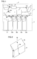
- Fig. 1 is a schematic internal sectional view showing a construction of a main part of the banknote handling machine according to an embodiment of this invention.
- a banknote handling machine 1 of this embodiment is constructed by an upper unit 2 and a lower unit 3 separable each other.
- the upper unit 2 includes a banknote identifying part 11 for determining the banknotes as true or false, denominations of the banknotes and the like, a deposit and withdrawal port 12 into which users input banknotes or from which banknotes are discharged to users, a temporary holding part 13 for temporarily holding the identified banknotes in the banknote identifying part 11, and a return holding part 14 for temporarily holding the banknotes (banknotes to be returned to the users) of which truth or falsehood and denomination cannot be determined in the banknote identifying part 11 among the banknotes inputted into the banknote introducing port 12 by the users.
- the lower unit 3 includes a recovering cartridge 21 for recovering banknotes and the like which the user forgets to take, and a cartridge 22 (22a to 22d) distinguished by denominations for housing the banknotes provided in accordance with denominations.
- the cartridge 22a houses thousand-yen notes
- the cartridge 22 b houses five thousand-yen notes
- the cartridges 22c and 22d house ten thousand-yen notes.
- banknote transfer passages for transferring the banknotes in the direction shown in the drawing are formed.
- the banknote transfer passages are connected at a point A where the banknotes are transferred to the lower unit 3 from the upper unit 2, and a point B where the banknotes are transferred to the upper unit 2 from the lower unit 3 when the upper unit 2 and the lower unit 3 are connected.
- the banknote transfer passage has a plurality of branch points, and each branch point is provided with a flapper for switching the destination of a banknote.
- a flapper 15a shown in the drawing switches the destination of a banknote between the banknote identifying part 11 and the deposit and withdrawal port 12, a flapper 15b switches the destination of a banknote between the lower unit 3, and the temporary holding part 13 or the return holding part 14, and a flapper 15c switches the destination of a banknote between the temporary holding part 13 and the return holding part 14.
- Flappers 23a to 23e which are provided at the lower unit 3 switch the transference of a banknote to the recovering cartridge 21 or the cartridge 22 (22a to 22d) by the denominations, and the transference to the upper unit 2. Further, a banknote transfer passage for transferring the banknotes paid out of the banknote cartridge 22 (22a to 22d) to the upper unit 2 is formed in the lower unit 3.
- a user inputs banknotes to be deposited into the deposit and withdrawal port 12.
- the banknote handling machine 1 pays out the banknotes inputted into the deposit and withdrawal port 12 one by one, and transfers them to the banknote identifying part 11.
- the banknote identifying part 11 truth or falsehood, and denominations are determined for each transferred banknote.
- the banknote identified in the banknote identifying part 11 is not transferred to the lower unit 3 side, but is transferred to the side of the temporary holding part 13 and the return holding part 14.
- the banknotes which are determined as a true note and of which denominations are determined are held in the temporary holding part 13, and the banknote at least whose truth or denomination is not identified is held in the return holding part 14. Switching of the transfer destination of the banknotes in the banknote transfer passage is performed by switching of the flappers 15b and 15c.
- the banknote handling machine 1 When the banknote handling machine 1 identifies all the banknotes inputted into the deposit and withdrawal port 12 in the banknote identifying part 11, it pays out the banknotes held in the return holding part 14 this time one by one, and transfers them to the deposit and withdrawal port 12. When the banknote handling machine 1 transfers all the banknotes held in the return holding part 14 this time to the deposit and withdrawal port 12, it switches the flapper 15a, and pays out the banknotes held in the temporary storing part 13 this time one by one, transfers them to the banknote identifying part 11 again, and determines truth or falsehood and denominations of them.
- the banknote handling machine 1 does not transfer banknotes which are identified again in the banknote identifying part 11 to the side of the temporary holding part 13 and the return holding part 14, but transfers them to the side of point A. Switching of the transfer destination of the banknotes can be performed by switching of the flapper 15b.
- the banknote handling machine 1 transfers each banknote to the cartridges 22a to 22d distinguished by denominations in accordance with the denomination when each banknote is identified again, and the banknote at least whose truth or denomination is not identified when it is identified again is transferred to the recovering cartridge 21.
- the banknote handling machine 1 controls the flappers 23a to 23e for each banknote transferred to the lower unit 3, and transfers and houses the banknotes into the corresponding cartridges 21, 22a to 22d.
- the withdrawal amount is inputted by a user in a display operating part not shown.
- the banknote handling machine 1 determines the number of banknotes to be withdrawn for each denomination based on the inputted amount to be withdrawn.
- the banknote handling machine 1 pays out the banknotes, of which number is determined here, one by one from the cartridges 22a to 22d distinguished by the denominations for each denomination.
- the banknotes paid out of the cartridges 22a to 22d distinguished by denominations are transferred to the banknote identifying part 11 at the side of the upper unit 2 via point B. In the banknote identifying part 11, truth or falsehood and denomination are determined for each transferred banknote.
- the banknote handling machine 1 transfers the banknote which is determined as a true note and whose denomination is determined in the banknote identifying part 11 to the temporary holding part by controlling the flappers 15b and 15c, and the banknote handling machine 1 transfers the banknote at least whose truth or denomination is not determined to the recovering cartridge 21.
- the banknote handling machine 1 After the banknote handling machine 1 holds the amount of banknotes to be withdrawn this time into the temporary holding part 13, it pays out the banknotes held in the temporary holding part 13 one by one and transfers them to the deposit and withdrawal port 12. The user takes out the banknotes from this deposit and withdrawal port 12.
- the banknote handling machine 1 pays out this banknote from the deposit and withdrawal port 12 and transfers it along the banknote transfer passage and houses it into the recovery cartridge 21.
- the deposit and withdrawal port 12, the temporary holding part 13, the return holding part 14, the recovering cartridge 21 and the cartridge 22 (22a to 22d) distinguished by denominations correspond to the sheet housing part called in this invention.
- a pair of guide members are mounted to each of the deposit and withdrawal port 12, the temporary holding part 13, the return holding part 14, the recovery cartridge 21, and the cartridge 22 distinguished by denomination (22a to 22d).
- a pair of guide members are mounted, with a space between them adjusted in accordance with the banknote with the largest width dimension which is handled in the machine body.
- a pair of guide members are mounted, with the space between a pair of guide members adjusted in accordance with the banknotes of the denominations housed therein.
- the deposit and withdrawal port 12 has a door not shown on a top surface. By opening and closing the door, input of the banknotes deposited by the users, and taking out of the banknotes to be withdrawn are limited. On a bottom surface side of the deposit and withdrawal port 12, a pickup roller for paying out the banknotes inputted into the deposit and withdrawal port 12, and a transfer roller for feeding the banknotes to be withdrawn into the deposit and withdrawal port 12 are disposed.
- FIG. 2 is a view showing the guide member
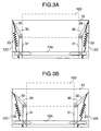
- Figs. 3A and 3B are views showing a state in which a pair of guide members are attached to the deposit and withdrawal port.
- a guide member 30 is constructed by an upright member 31 which is fixed to a mounting bar 12a provided at a bottom surface of the deposit and withdrawal port 12, a swinging member 32 pivotably mounted to a tip end of the upright member 31, and a spring 33 for connecting the upright member 31 and the swinging member 32 at a side of a side wall of the deposit and withdrawal port 12.
- the mounting bar 12a for mounting the guide member 30 is provided at the side of the bottom surface of the deposit and withdrawal port 12.
- This mounting bar 12a Long holes are formed in this mounting bar 12a at both sides, so that the positions at which a pair of guide members 30 (upright members 31) are mounted can be adjusted in a width direction, and the space between the upright members 31 can be adjusted as shown in Figs. 3A and 3B.
- the space between the upright members is determined in accordance with the width size of the banknote 100 to be housed. Accordingly, even in the machine in which different banknotes 100 with the largest width dimension are handled, the banknotes 100 can be housed by being aligned by only adjusting the space between the upright members 31.
- the swinging member 32 swings to the side of the side wall 122 of the deposit and withdrawal port 12 by biasing power provided by the spring 33, and its tip end stops in the state in which it abuts to the side wall 122 of the deposit and withdrawal port 12. Accordingly, as shown in Figs. 3A and 3B, the swinging member 32 stops in the state in which the tip end of the swinging member 32 abuts to the side wall 122 of the deposit and withdrawal port 12 irrespective of the space between the upright members 31 mounted to the deposit and withdrawal port 12 by being adjusted. Therefore, even if a gap occurs between the side wall 122 of the deposit and withdrawal port 12 and the guide member 30, the top surface of the gap is closed by the swinging member 32, and therefore, a foreign matter can be prevented from entering the gap.
- the banknote handling machine 1 not only the above described deposit and withdrawal port 12, but also the temporary holding part 13, the return holding part 14, the recovering cartridge 21 and the cartridge 22 distinguished by denomination (22a to 22d) are provided with the mounting bars with long holes formed therein so that the aforementioned pair of guide members 30 are mounted with a space corresponding to the banknotes 100 housed therein provided therebetween so that the banknotes 100 can be housed by being aligned.
- Positioning holes may be formed at the mounting positions of the upright members 31 for each kind of banknote 100 in the mounting bar 12a instead of the long holes, and the guide member 30 may be mounted by utilizing this hole. Thereby, adjustment of the mounting positions can be facilitated at the time of mounting the guide members 30, and operability can be enhanced.
- the upright member 31 and the swinging member 32 are connected with the spring 33, but they may be connected with another elastic body such as rubber.
- a pair of guide members 30 are mounted with the space therebetween adjusted in accordance with the width dimension of the banknote 100 to be housed, but the construction in which one guide member 30 is mounted to one of the side walls 122 with the space from the one side wall 122 adjusted may be adopted as shown in Figs. 4A and 4B.
- the same effect as the above described embodiment can be also provided, the required number of guide members 30 is reduced to half, and the machine body can be made at low cost.
- the guide member in the above described embodiment has the structure of closing the gap inlet between the housing part side surface and the guide member by the construction of the upright member 31, the swinging member 32 and the spring 33, but as the alternatives to the structure of closing the gap or the gap inlet, the same effect can be expected from the structures of, for example, (1) providing the guide member with a member of which volume expands or shrinks as the size of the housing part is adjusted by the guide member, and (2) using a sliding type lid which extends to contact the housing part side surface and closes the gap inlet as the lid for closing the inlet of the gap as the size of the housing part is adjusted, for the guide member, instead of the turning type lid.
Landscapes
- Physics & Mathematics (AREA)
- General Physics & Mathematics (AREA)
- Pile Receivers (AREA)
- Sheets, Magazines, And Separation Thereof (AREA)
Abstract
Description
At this time, the banknote handling machine 1 controls the
Claims (5)
- A sheet handling machine (1), comprising:wherein said guide member (30) has a mechanism for closing a gap provided between the guide member (30) and the side wall (122) of said housing part (22).a sheet housing part (22) for piling up and housing sheets; anda guide member (30) mounted to at least one of side walls (122) of said sheet housing part (22) to be capable of adjusting a size of a housing space of the sheet housing part (22),
- The sheet handling machine according to claim 1, wherein said guide member (30) comprises an upright member (31) vertically provided at a bottom surface of said sheet housing part (22) toward a top surface from which banknotes to be housed come in, a swinging member (32) pivotably mounted to an upper portion of the raised member (31), and a biasing member for exerting a swinging force swinging to a side of the side wall (122) onto the swinging member (32).
- The sheet handling machine according to claim 1, wherein said guide members (30) are provided at both side walls (122) of said housing part (22).
- The sheet handling machine according to claim 1, wherein said guide member (30) is provided at one of the side walls (122) of said housing part (22).
- The sheet handling machine according to claim 2, wherein said biasing member is an elastic member (33) for connecting said upright member (32) provided at the side of the side wall (122), and the swinging member (31).
Applications Claiming Priority (2)
| Application Number | Priority Date | Filing Date | Title |
|---|---|---|---|
| JP2004057542A JP4346475B2 (en) | 2004-03-02 | 2004-03-02 | Paper sheet processing equipment |
| JP2004057542 | 2004-03-02 |
Publications (2)
| Publication Number | Publication Date |
|---|---|
| EP1607915A1 true EP1607915A1 (en) | 2005-12-21 |
| EP1607915B1 EP1607915B1 (en) | 2007-05-23 |
Family
ID=34917916
Family Applications (1)
| Application Number | Title | Priority Date | Filing Date |
|---|---|---|---|
| EP05004379A Expired - Lifetime EP1607915B1 (en) | 2004-03-02 | 2005-02-28 | Sheet handling machine |
Country Status (6)
| Country | Link |
|---|---|
| US (1) | US7384037B2 (en) |
| EP (1) | EP1607915B1 (en) |
| JP (1) | JP4346475B2 (en) |
| CN (1) | CN100460300C (en) |
| DE (1) | DE602005001174T2 (en) |
| TW (1) | TWI265462B (en) |
Families Citing this family (18)
| Publication number | Priority date | Publication date | Assignee | Title |
|---|---|---|---|---|
| JP4292012B2 (en) * | 2003-02-10 | 2009-07-08 | 日立オムロンターミナルソリューションズ株式会社 | Banknote deposit and withdrawal device |
| US7140608B2 (en) * | 2004-10-28 | 2006-11-28 | International Currency Technology Corporation | Bill box for bill acceptor |
| JP2007156733A (en) * | 2005-12-02 | 2007-06-21 | Toshiba Corp | Paper sheet processing equipment |
| JP4951251B2 (en) * | 2006-02-27 | 2012-06-13 | 日立オムロンターミナルソリューションズ株式会社 | Automatic cash transaction equipment |
| JP2008308243A (en) * | 2007-06-12 | 2008-12-25 | Gradco Japan Ltd | Sheet processing apparatus and stacker provided with the same |
| JP2009078918A (en) * | 2007-09-05 | 2009-04-16 | Fujifilm Corp | Sheet stacking apparatus and sheet stacking method |
| EP2033918A3 (en) * | 2007-09-05 | 2011-11-02 | FUJIFILM Corporation | Sheet stacking apparatus and sheet stacking method |
| JP5157939B2 (en) * | 2009-01-29 | 2013-03-06 | 沖電気工業株式会社 | Banknote handling equipment |
| JP5280976B2 (en) * | 2009-08-31 | 2013-09-04 | 富士通フロンテック株式会社 | Paper handling equipment |
| JP5384278B2 (en) * | 2009-10-05 | 2014-01-08 | 日立オムロンターミナルソリューションズ株式会社 | Banknote handling equipment |
| JP5410932B2 (en) * | 2009-11-25 | 2014-02-05 | 日立オムロンターミナルソリューションズ株式会社 | Banknote handling equipment |
| JP5582222B2 (en) * | 2013-05-08 | 2014-09-03 | 沖電気工業株式会社 | Banknote deposit and withdrawal machine |
| JP6591787B2 (en) * | 2015-06-03 | 2019-10-16 | 日立オムロンターミナルソリューションズ株式会社 | Automatic cash transaction equipment |
| JP6794697B2 (en) * | 2016-07-21 | 2020-12-02 | 沖電気工業株式会社 | Media processing equipment and media trading equipment |
| JP6794696B2 (en) * | 2016-07-21 | 2020-12-02 | 沖電気工業株式会社 | Media processing equipment and media trading equipment |
| CN109427128B (en) * | 2017-08-25 | 2021-03-19 | 山东新北洋信息技术股份有限公司 | Bank note box and cash recycling machine using bank note box |
| US12148261B2 (en) * | 2022-12-27 | 2024-11-19 | Japan Cash Machine Co., Ltd. | Cashbox unit |
| JP7673102B2 (en) * | 2023-01-12 | 2025-05-08 | 日本金銭機械株式会社 | Transport System |
Citations (1)
| Publication number | Priority date | Publication date | Assignee | Title |
|---|---|---|---|---|
| JP2001101479A (en) * | 1999-10-01 | 2001-04-13 | Omron Corp | Paper processing equipment and banknote processing equipment |
Family Cites Families (7)
| Publication number | Priority date | Publication date | Assignee | Title |
|---|---|---|---|---|
| US3907128A (en) * | 1973-12-13 | 1975-09-23 | Ppg Industries Inc | Lead edge stop device |
| DE3618622A1 (en) * | 1986-06-03 | 1987-12-10 | Roland Man Druckmasch | BACK EDGE STOP AT BOW BOOMS ON BOW-PROCESSING MACHINES |
| JPH05310359A (en) * | 1992-05-11 | 1993-11-22 | Fujitsu Ltd | Aligning device for paper sheet |
| US5374051A (en) * | 1993-04-21 | 1994-12-20 | Xerox Corporation | Relief device for offset stacker tamping mechanism |
| US6572102B2 (en) * | 2001-10-18 | 2003-06-03 | Multifeeder Technology, Inc. | Catch tray for sheet feeder with adjustable depth feature |
| KR100431006B1 (en) * | 2002-05-10 | 2004-05-12 | 삼성전자주식회사 | Paper cartridge for printer |
| JP4160362B2 (en) * | 2002-10-30 | 2008-10-01 | グローリー株式会社 | Accumulator and circulating banknote deposit and withdrawal machine |
-
2004
- 2004-03-02 JP JP2004057542A patent/JP4346475B2/en not_active Expired - Fee Related
-
2005
- 2005-02-17 TW TW094104681A patent/TWI265462B/en not_active IP Right Cessation
- 2005-02-28 EP EP05004379A patent/EP1607915B1/en not_active Expired - Lifetime
- 2005-02-28 DE DE602005001174T patent/DE602005001174T2/en not_active Expired - Lifetime
- 2005-03-01 US US11/068,435 patent/US7384037B2/en not_active Expired - Fee Related
- 2005-03-01 CN CNB2005100515051A patent/CN100460300C/en not_active Expired - Fee Related
Patent Citations (1)
| Publication number | Priority date | Publication date | Assignee | Title |
|---|---|---|---|---|
| JP2001101479A (en) * | 1999-10-01 | 2001-04-13 | Omron Corp | Paper processing equipment and banknote processing equipment |
Non-Patent Citations (1)
| Title |
|---|
| PATENT ABSTRACTS OF JAPAN vol. 2000, no. 21 3 August 2001 (2001-08-03) * |
Also Published As
| Publication number | Publication date |
|---|---|
| JP2005250643A (en) | 2005-09-15 |
| JP4346475B2 (en) | 2009-10-21 |
| TW200534187A (en) | 2005-10-16 |
| US7384037B2 (en) | 2008-06-10 |
| CN1673058A (en) | 2005-09-28 |
| EP1607915B1 (en) | 2007-05-23 |
| TWI265462B (en) | 2006-11-01 |
| US20050200072A1 (en) | 2005-09-15 |
| DE602005001174T2 (en) | 2008-01-24 |
| CN100460300C (en) | 2009-02-11 |
| DE602005001174D1 (en) | 2007-07-05 |
Similar Documents
| Publication | Publication Date | Title |
|---|---|---|
| US7384037B2 (en) | Sheet handling machine | |
| CN100545877C (en) | Bezel device for automatic teller machine | |
| US9070241B2 (en) | Bill storage box and bill handling device | |
| CN101276493B (en) | Paper processing apparatus | |
| US9142076B2 (en) | Media case and banking machine | |
| JP4878516B2 (en) | Paper sheet stacking device | |
| JP6241363B2 (en) | Medium processing apparatus and medium storage cassette | |
| KR101016245B1 (en) | Withdrawal device of automatic teller machine | |
| KR102323439B1 (en) | Automatic teller machine for paper money | |
| KR20110069961A (en) | Open Structure of Banknote Module | |
| JP2022171617A (en) | Banknote processing equipment | |
| KR20110079344A (en) | Door open / close detection device of reject box | |
| KR100696993B1 (en) | Initialization method of automatic teller machine and automatic teller machine | |
| JP4838998B2 (en) | Banknote deposit and withdrawal machine | |
| KR20100080217A (en) | Temporary stacker of atm | |
| KR101199145B1 (en) | Apparatus for locking the front panel of ATM | |
| KR200377537Y1 (en) | Apparatus of supplying bills in a cash transaction machine | |
| KR200389004Y1 (en) | Apparatus of drawing bills in a cash transaction machine | |
| KR200393555Y1 (en) | Cash transaction machine | |
| KR20060042596A (en) | Banknote storage device of automatic teller machine | |
| KR200393046Y1 (en) | Device of locking for cassette | |
| KR101177936B1 (en) | Structure for drawing a bill in a cash transaction machine | |
| KR200374274Y1 (en) | Apparatus of receiving bills in a cash transaction machine | |
| KR100492462B1 (en) | Longitudinally bill-receiving atm | |
| KR20100080110A (en) | Apparatus for receiving and dispensing money in atm |
Legal Events
| Date | Code | Title | Description |
|---|---|---|---|
| PUAI | Public reference made under article 153(3) epc to a published international application that has entered the european phase |
Free format text: ORIGINAL CODE: 0009012 |
|
| AK | Designated contracting states |
Kind code of ref document: A1 Designated state(s): AT BE BG CH CY CZ DE DK EE ES FI FR GB GR HU IE IS IT LI LT LU MC NL PL PT RO SE SI SK TR |
|
| AX | Request for extension of the european patent |
Extension state: AL BA HR LV MK YU |
|
| 17P | Request for examination filed |
Effective date: 20060331 |
|
| AKX | Designation fees paid |
Designated state(s): CH DE LI |
|
| GRAP | Despatch of communication of intention to grant a patent |
Free format text: ORIGINAL CODE: EPIDOSNIGR1 |
|
| RIN1 | Information on inventor provided before grant (corrected) |
Inventor name: HAYASHI, SHUNSUKEC/O HITACHI-OMRON T. S. CORP. Inventor name: SAWAYAMA, HIDEYUKIC/O HITACHI-OMRON T. S. CORP. Inventor name: TOKUNAGA, DAISUKEC/O HITACHI-OMRON T. S. CORP. Inventor name: MIZUNO, SHOC/O HITACHI-OMRON T. S. CORP. |
|
| GRAS | Grant fee paid |
Free format text: ORIGINAL CODE: EPIDOSNIGR3 |
|
| GRAA | (expected) grant |
Free format text: ORIGINAL CODE: 0009210 |
|
| AK | Designated contracting states |
Kind code of ref document: B1 Designated state(s): CH DE LI |
|
| REG | Reference to a national code |
Ref country code: CH Ref legal event code: EP |
|
| REG | Reference to a national code |
Ref country code: CH Ref legal event code: NV Representative=s name: TROESCH SCHEIDEGGER WERNER AG |
|
| REF | Corresponds to: |
Ref document number: 602005001174 Country of ref document: DE Date of ref document: 20070705 Kind code of ref document: P |
|
| PLBE | No opposition filed within time limit |
Free format text: ORIGINAL CODE: 0009261 |
|
| STAA | Information on the status of an ep patent application or granted ep patent |
Free format text: STATUS: NO OPPOSITION FILED WITHIN TIME LIMIT |
|
| 26N | No opposition filed |
Effective date: 20080226 |
|
| PGFP | Annual fee paid to national office [announced via postgrant information from national office to epo] |
Ref country code: CH Payment date: 20100118 Year of fee payment: 6 |
|
| PGFP | Annual fee paid to national office [announced via postgrant information from national office to epo] |
Ref country code: DE Payment date: 20100318 Year of fee payment: 6 |
|
| REG | Reference to a national code |
Ref country code: CH Ref legal event code: PL |
|
| PG25 | Lapsed in a contracting state [announced via postgrant information from national office to epo] |
Ref country code: LI Free format text: LAPSE BECAUSE OF NON-PAYMENT OF DUE FEES Effective date: 20110228 Ref country code: CH Free format text: LAPSE BECAUSE OF NON-PAYMENT OF DUE FEES Effective date: 20110228 |
|
| REG | Reference to a national code |
Ref country code: DE Ref legal event code: R119 Ref document number: 602005001174 Country of ref document: DE Effective date: 20110901 |
|
| PG25 | Lapsed in a contracting state [announced via postgrant information from national office to epo] |
Ref country code: DE Free format text: LAPSE BECAUSE OF NON-PAYMENT OF DUE FEES Effective date: 20110901 |