EP1607817A1 - Procédé et dispositif de guidage d'un aéronef pour l'aide au parachutage - Google Patents
Procédé et dispositif de guidage d'un aéronef pour l'aide au parachutage Download PDFInfo
- Publication number
- EP1607817A1 EP1607817A1 EP05290753A EP05290753A EP1607817A1 EP 1607817 A1 EP1607817 A1 EP 1607817A1 EP 05290753 A EP05290753 A EP 05290753A EP 05290753 A EP05290753 A EP 05290753A EP 1607817 A1 EP1607817 A1 EP 1607817A1
- Authority
- EP
- European Patent Office
- Prior art keywords
- aircraft
- point
- flight
- flight path
- altitude
- Prior art date
- Legal status (The legal status is an assumption and is not a legal conclusion. Google has not performed a legal analysis and makes no representation as to the accuracy of the status listed.)
- Granted
Links
- 238000000034 method Methods 0.000 title claims abstract description 19
- 230000007704 transition Effects 0.000 claims abstract description 52
- 238000011144 upstream manufacturing Methods 0.000 claims description 6
- 230000001960 triggered effect Effects 0.000 claims description 3
- 230000000873 masking effect Effects 0.000 description 6
- 238000013459 approach Methods 0.000 description 5
- 230000001133 acceleration Effects 0.000 description 3
- 230000000007 visual effect Effects 0.000 description 3
- 238000012800 visualization Methods 0.000 description 3
- 238000012550 audit Methods 0.000 description 2
- 241001080024 Telles Species 0.000 description 1
- 230000003466 anti-cipated effect Effects 0.000 description 1
- 238000010586 diagram Methods 0.000 description 1
- 230000000694 effects Effects 0.000 description 1
- 210000000056 organ Anatomy 0.000 description 1
Images

Classifications
-
- G—PHYSICS
- G01—MEASURING; TESTING
- G01C—MEASURING DISTANCES, LEVELS OR BEARINGS; SURVEYING; NAVIGATION; GYROSCOPIC INSTRUMENTS; PHOTOGRAMMETRY OR VIDEOGRAMMETRY
- G01C5/00—Measuring height; Measuring distances transverse to line of sight; Levelling between separated points; Surveyors' levels
- G01C5/005—Measuring height; Measuring distances transverse to line of sight; Levelling between separated points; Surveyors' levels altimeters for aircraft
-
- G—PHYSICS
- G05—CONTROLLING; REGULATING
- G05D—SYSTEMS FOR CONTROLLING OR REGULATING NON-ELECTRIC VARIABLES
- G05D1/00—Control of position, course, altitude or attitude of land, water, air or space vehicles, e.g. using automatic pilots
- G05D1/10—Simultaneous control of position or course in three dimensions
- G05D1/101—Simultaneous control of position or course in three dimensions specially adapted for aircraft
- G05D1/105—Simultaneous control of position or course in three dimensions specially adapted for aircraft specially adapted for unpowered flight, e.g. glider, parachuting, forced landing
-
- G—PHYSICS
- G05—CONTROLLING; REGULATING
- G05D—SYSTEMS FOR CONTROLLING OR REGULATING NON-ELECTRIC VARIABLES
- G05D1/00—Control of position, course, altitude or attitude of land, water, air or space vehicles, e.g. using automatic pilots
- G05D1/10—Simultaneous control of position or course in three dimensions
- G05D1/101—Simultaneous control of position or course in three dimensions specially adapted for aircraft
- G05D1/106—Change initiated in response to external conditions, e.g. avoidance of elevated terrain or of no-fly zones
Definitions
- the present invention relates to a method and a guiding device of an aircraft.
- the guidance of the aircraft is implemented at less on an intermediate trajectory between a first trajectory of flight for a low-altitude flight, and a second flight path that starts at an initial point, and from which a parachute is made.
- the present invention therefore applies to parachuting from a aircraft, in particular of a military transport aircraft, of elements, in particular equipment and / or troops, which must be parachuted onto a determined reception area on the ground.
- a parachute it is necessary that the aircraft arrives stabilized at the right speed (with proper acceleration), at the right altitude and in a suitable aerodynamic configuration at the initial point corresponding to the beginning of the said (second) trajectory of flight, during which the parachuting is carried out.
- the aircraft is generally flown along a trajectory approach at low altitude, up to said second trajectory of flight, to allow the aircraft to benefit from masking by the ground and thus not be easily detectable.
- the pilot of such an aircraft generally only information about a deceleration point which is located upstream of the said initial point, and from which it is advisable to decelerate the aircraft.
- this deceleration point does not hold account of the terrain profile as it approaches the parachute zone, and the The pilot must therefore manually adjust the piloting of the aircraft to reach said initial point to the aforementioned special conditions, which is of course very difficult to achieve.
- the present invention relates to a method for guiding an aircraft at least on an intermediate trajectory between a first trajectory flight for a low-altitude flight and a second flight path which starts at an initial point, and from which is made a parachute, guiding method that overcomes the aforementioned drawbacks.
- said intermediate trajectory corresponds to a line segment connecting said transition point to said point initial.
- the aircraft can continue to fly low or return to a low-altitude flight after the phase parachuting (with parachuting done, interrupted or abandoned), and thus benefit from masking by the ground.
- the present invention also relates to a guiding device of an aircraft at least on an intermediate trajectory between a first flight path for a low-level flight and a second trajectory flight that starts at an initial point, and from which a parachuting.
- the device according to the invention therefore provides valuable assistance allowing an aircraft flying at low altitude to reach the beginning a parachuting phase in the best possible conditions, both in manual guidance and automatic guidance.
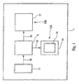
- FIG. 1 is the block diagram of a device according to the invention.
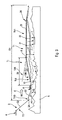
- Figures 2 and 3 are two graphs, respectively in the lateral plane and in the vertical plane, to explain the characteristics of the present invention.
- the guiding device considered here is a guiding device aircraft A, in particular a military transport aircraft, which allows the implementation, in the usual way, of a manual guidance by a pilot of the aircraft A and / or an automatic guidance, for example via an autopilot system.
- Characteristics essential of such a guiding device are known and do not enter directly in account in the context of the present invention. Also for reasons for simplification of the drawing, only the characteristics used for the implementation of the present invention have been represented in Figure 1.
- Said guiding device 1 makes it possible to guide the aircraft A along of a flight trajectory TO comprising a defined lateral trajectory TL0 in a lateral plane and partially shown in Figure 2 and a trajectory Vertical TV0 (or flight profile) defined in a vertical plane and represented partially in Figure 3.
- this flight trajectory TO includes a flight section SV at low altitude that starts at a point 2A, for example following a descent 3 from a cruise phase 4 at stabilized altitude, and ends at a point 2B.
- the flight path TO (at low altitude) must allow the aircraft A to follow closely the terrain overflown 5.
- the vertical trajectory TV0 is calculated, on this section SV of low-level flight, from a PT terrain profile that is located (at a predetermined guard height HG) above the relief 6 of the terrain 5 overflown, as shown on Figure 3.
- said flight path TO is a so-called string trajectory that consists of straight segments (Straight segments S1 in the lateral plane, separated by waypoints P1 as shown in Figure 2, and straight segments S2 in the vertical plane as shown in FIG. lateral and vertical transitions are constant radius arcs which are derived from setpoint speed considerations and maximum allowable load.
- the flight path can also be continuously curved in the vertical plane and / or in the plane lateral.
- This flight trajectory TO can be an anticipated trajectory, determined using predicted climb and descent performance. Of more, it is calculated using a digital database of the field and marry, at best and as close as possible, the configuration of the relief 6 of the ground 5 flew over.
- the present invention relates to the case, where during a flight on a such low altitude flight section SV, a parachuting phase must to be implemented.
- a parachuting phase consists of parachuting, on a reception area 7 determined on the ground, elements such as equipment and / or troops.
- elements such as equipment and / or troops.
- the aircraft A arrives so stabilized at an appropriate speed and in an aerodynamic configuration appropriate, at an initial point 8 corresponding to the beginning of a section flight path T1 (with a lateral trajectory TL1 and a trajectory vertical TV1 which is located at a height H1 above the ground), during from which is made the parachuting. He must also respect slope, acceleration, time, etc.
- configuration aerodynamic particular, a particular combination of positions movable elements (high lift flaps, landing gear, ...), on which the aerodynamic characteristics of the aircraft depend AT.
- the present invention applies equally well to a flight in conditions VMC ("Visual Meteorological Conditions"), that is to say meteorological conditions of visual flight that are expressed according to visibility, distance from clouds and ceiling, conditions equal to or greater than specified minima, than on a flight under IMC ("Instrument Meteorological Conditions” in English), that is to say instrument meteorological conditions that are expressed depending on the visibility, the distance from the clouds and the ceiling, ie conditions below the minimums specified for visual meteorological conditions.
- VMC Vehicle Meteorological Conditions
- IMC Instrument Meteorological Conditions
- Said set 11 of information sources also provides the time, slope, acceleration, ..., chosen by the operator.
- the aircraft A can reach the point 8 of the flight path T1 in a stabilized manner, that is to say at the predetermined speed and altitude and in the configuration planned aerodynamics, while respecting the instructions of time, slope, deceleration, ...
- This is very important to allow parachuting under the best possible stability conditions, after a approach at low altitude which is often unstable, since aircraft A then follows as much as possible the relief 6 of the ground 5 for reasons of masking especially.
- the device 1 according to the invention therefore allows to increase the comfort of driving, and to reduce the workload of the crew in such an approach phase which is often very demanding, while allowing to reach said initial point 8 in the best possible conditions.
- the vertical trajectory TVi of the intermediate trajectory Ti corresponds to the segment of the line 13B, which is located between the initial point 8 and the transition point 12 determined in the manner specified above.
- the parachuting can be realized in the best conditions possible.
- said display means 14 also exhibit at least said point 24 to the pilot of the aircraft A. This point 24 corresponds to the beginning of an intermediate flight phase to join said trajectory TO at low altitude.
- end point 2B of low altitude section SV is located downstream of the said point 24, in the direction of flight E of the aircraft A, this the last continues to fly low after the parachuting, and thus to benefit from a masking by the ground 5.
Landscapes
- Engineering & Computer Science (AREA)
- Radar, Positioning & Navigation (AREA)
- Remote Sensing (AREA)
- Physics & Mathematics (AREA)
- General Physics & Mathematics (AREA)
- Aviation & Aerospace Engineering (AREA)
- Automation & Control Theory (AREA)
- Navigation (AREA)
- Traffic Control Systems (AREA)
- Control Of Position, Course, Altitude, Or Attitude Of Moving Bodies (AREA)
- Position Fixing By Use Of Radio Waves (AREA)
- Toys (AREA)
Abstract
Description
- une vitesse prédéterminée ;
- une altitude prédéterminée ;
- une configuration aérodynamique prédéterminée de l'aéronef ;
- un taux de décélération ;
- un horaire de parachutage à respecter ; et
- une pente sol maximale de rejointe de l'altitude de parachutage.
- dans une première variante relative notamment à un guidage manuel, à l'étape b), on présente ledit point de transition à un pilote de l'aéronef ; et
- dans une seconde variante, lorsque l'aéronef est guidé automatiquement, le guidage automatique pour suivre ladite trajectoire intermédiaire est déclenché audit point de transition.
- on projette dans le plan vertical, à partir dudit point initial, en amont, une première droite présentant une première pente qui est positive et une seconde droite présentant une seconde pente qui est négative ;
- on détermine, dans le plan vertical, les différents points de croisement entre, d'une part, lesdites première et seconde droites et, d'autre part, ladite première trajectoire de vol ; et
- on choisit, comme point de transition, l'un desdits points de croisement, à savoir celui qui est situé le plus près dudit point initial, pour bénéficier le plus longtemps possible du masquage par le terrain.
- à l'étape a), on détermine, de plus :
- au moins un premier point auxiliaire correspondant à un point de changement de vitesse où l'aéronef doit décélérer ; et/ou
- au moins un second point auxiliaire correspondant à un point de changement de configuration aérodynamique de l'aéronef. On prévoit généralement plusieurs seconds points auxiliaires qui sont relatifs respectivement aux différentes configurations aérodynamiques successives à commander avant d'arriver à la configuration aérodynamique adéquate ; et
- à l'étape b), on utilise ledit premier point auxiliaire et/ou ledit second point auxiliaire pour piloter l'aéronef.
- ladite première trajectoire de vol, pour un vol à basse altitude, en amont de ladite deuxième trajectoire de vol ; et
- une troisième trajectoire de vol, également pour un vol à basse altitude, en aval de ladite deuxième trajectoire de vol.
- à l'étape a), on détermine de plus un point de transition auxiliaire, qui se trouve sur ladite deuxième trajectoire de vol, qui représente le début d'une trajectoire intermédiaire auxiliaire entre lesdites deuxième et troisième trajectoires de vol, et qui correspond au point où l'aéronef doit quitter ladite deuxième trajectoire de vol pour rejoindre ladite troisième trajectoire de vol ; et
- à l'étape b), on utilise ledit point de transition auxiliaire pour guider l'aéronef entre lesdites deuxième et troisième trajectoires de vol.
- des premiers moyens pour déterminer un point de transition qui se trouve sur ladite première trajectoire de vol, qui représente le début de ladite trajectoire intermédiaire, et qui correspond au point où l'aéronef doit quitter ladite première trajectoire de vol pour atteindre ledit point initial dans des conditions de vol prédéterminées ; et
- des seconds moyens qui utilisent ledit point de transition pour aider au guidage de l'aéronef entre lesdites première et deuxième trajectoires de vol.
- des moyens d'affichage pour présenter ledit point de transition sur au moins un écran de visualisation, de type tête haute ou de type tête basse, en coupe horizontale et/ou verticale ; et/ou
- un système de guidage automatique (déclenchable par un pilote) pour guider automatiquement ledit aéronef au moins le long de ladite trajectoire intermédiaire.
- des moyens 9 qui sont reliés par une liaison 10 à un ensemble 11 de
sources d'informations et qui permettent de déterminer un point de
transition 12 :
- qui se trouve sur ladite trajectoire de vol TO à basse altitude ;
- qui représente le début d'une trajectoire intermédiaire Ti, dont la trajectoire verticale TVi a été représentée sur la figure 3, ladite trajectoire intermédiaire Ti permettant de relier lesdites trajectoires TO et T 1 ; et
- qui correspond au point où l'aéronef A doit quitter ladite trajectoire
de vol TO à basse altitude pour atteindre ledit point initial 8 (de la
trajectoire de vol T1 de la phase de parachutage) dans des conditions
de vol prédéterminées. Dans un mode de réalisation préféré,
lesdites conditions de vol prédéterminées concernent au moins :
- une vitesse prédéterminée ;
- une altitude prédéterminée ;
- une configuration aérodynamique prédéterminée de l'aéronef A ;
- un taux de décélération ;
- un horaire de parachutage à respecter ; et
- une pente sol maximale de rejointe de l'altitude de parachutage ;
- des moyens 13A, 13B qui utilisent ledit point de transition 12 pour aider au guidage de l'aéronef A entre lesdites trajectoires de vol TO et T1.
- lesdits moyens 1 3A comprennent des moyens d'affichage 14 qui sont reliés par une liaison 1 5 aux moyens 9 et qui permettent de présenter sur un écran de visualisation 16 notamment ledit point de transition 12, ainsi que d'autres informations précisées ci-dessous. Ledit écran de visualisation 16 peut être un écran tête haute ou un écran tête basse. Il peut également s'agir d'un affichage horizontal ou d'un affichage vertical ; et
- lesdits moyens 13B comportent un système de guidage automatique usuel 17 qui est relié par une liaison 18 auxdits moyens 9. Ce système de guidage automatique usuel 17 comporte des moyens pour déterminer des ordres de pilotage et des moyens d'actionnement d'organes commandés (gouvernes, ...), auxquels sont appliqués ces ordres de pilotage.
- la trajectoire TO de vol à basse altitude, telle que prédite ;
- la procédure de parachutage planifiée avec la trajectoire de vol T1 ;
- une consigne de vitesse courante de l'aéronef A ; et
- le vecteur vitesse (position, vitesse, configuration aérodynamique) de l'aéronef A.
- ils projettent dans le plan vertical, à partir dudit point initial 8, comme représenté sur la figure 3, en amont (c'est-à-dire vers l'arrière, dans le sens contraire au sens de vol E de l'aéronef A) une première droite 13A présentant une pente α1 positive et une seconde droite 13B présentant une pente α2 négative. De préférence, les deux pentes α1 et α2 présentent la même valeur absolue, par exemple 3° ;
- ils déterminent, dans le plan vertical, les différents points de croisement entre, d'une part, lesdites droites 13A et 13B et, d'autre part, ladite trajectoire verticale TV0 ; et
- ils sélectionnent comme point de transition 12, l'un desdits points de croisement ainsi déterminés, à savoir celui qui est situé le plus près dudit point initial 8.
- des points auxiliaires correspondant à des points de changement de vitesse, où l'aéronef A doit décélérer, selon un taux de décélération prédéterminé, de manière à atteindre de façon stabilisée ledit point initial 8 à la bonne vitesse. Ceci est très important pour pouvoir réaliser un bon parachutage et dépend notamment du type d'éléments à parachuter. Le premier 1 9 desdits points auxiliaires peut être différent dudit point de transition 12, comme représenté sur la figure 3 qui montre également une phase de préparation 20 entre lesdits points 19 et 8 ; et
- des points auxiliaires supplémentaires (non représentés) correspondant à des points de changement de configuration aérodynamique de l'aéronef A. Ces points auxiliaires supplémentaires permettent également à l'aéronef A de ne pas arriver trop rapidement audit point initial 8.
- un point de lâcher 21 où les éléments à parachuter doivent être lâchés dudit aéronef A, et ceci au plus jusqu'à un point de fin de lâcher 22, pour que ces éléments puissent atteindre la zone de parachutage 7, comme illustré par des flèches F tenant compte de l'effet du vent. Ce point de lâcher 21 tient donc compte du vent qui pousse les parachutes : c'est ce qui explique l'écart latéral de ce point 21 par rapport à la piste 7 sur la figure 3 ;
- ledit point de fin de lâcher 22 ;
- un point 23 de fin de la séquence de parachutage ; et
- un point 24 de début de rattrapage de la trajectoire de vol TO à basse altitude.
Claims (15)
- Procédé de guidage d'un aéronef (A) au moins sur une trajectoire intermédiaire (Ti) entre une première trajectoire de vol (TO) pour un vol à basse altitude et une deuxième trajectoire de vol (T1) qui débute à un point initial (8), et à partir de laquelle est réalisé un parachutage,
caractérisé en ce que :a) on détermine un point de transition (12) qui se trouve sur ladite première trajectoire de vol (TO), qui représente le début de ladite trajectoire intermédiaire (Ti), et qui correspond au point où l'aéronef (A) doit quitter ladite première trajectoire de vol (TO) pour atteindre ledit point initial (8) dans des conditions de vol prédéterminées ; etb) on utilise ledit point de transition (12) pour guider l'aéronef (A) entre lesdites première et deuxième trajectoires de vol (TO, T1). - Procédé selon la revendication 1,
caractérisé en ce que lesdites conditions de vol prédéterminées concernent au moins certaines des conditions suivantes :une vitesse prédéterminée ;une altitude prédéterminée ;une configuration aérodynamique prédéterminée de l'aéronef (A) ;un taux de décélération ;un horaire de parachutage à respecter ; etune pente sol maximale de rejointe de l'altitude de parachutage. - Procédé selon l'une des revendications 1 et 2,
caractérisé en ce qu'à l'étape b), on présente ledit point de transition (12) à un pilote de l'aéronef (A). - Procédé selon l'une quelconque des revendications précédentes, caractérisé en ce que, lorsque l'aéronef (A) est guidé automatiquement, le guidage automatique pour suivre ladite trajectoire intermédiaire (Ti) est déclenché audit point de transition (12).
- Procédé selon l'une quelconque des revendications précédentes, caractérisé en ce qu'à l'étape a), pour déterminer ledit point de transition (12) :on projette dans le plan vertical, à partir dudit point initial (8), en amont, une première droite (13A) présentant une première pente (α1) qui est positive et une seconde droite (13B) présentant une seconde pente (α2) qui est négative ;on détermine, dans le plan vertical, les différents points de croisement entre, d'une part, lesdites première et seconde droites (13A, 13B) et, d'autre part, ladite première trajectoire de vol (TO) ; eton choisit, comme point de transition (12), l'un desdits points de croisement, à savoir celui qui est situé le plus près dudit point initial (8).
- Procédé selon l'une quelconque des revendications précédentes, caractérisé en ce que ladite trajectoire intermédiaire (Ti) correspond à un segment de droite reliant ledit point de transition (12) audit point initial (8).
- Procédé selon l'une quelconque des revendications précédentes, caractérisé en ce que :à l'étape a), on détermine, de plus, au moins un premier point auxiliaire (19) correspondant à un point de changement de vitesse où l'aéronef (A) doit décélérer ; età l'étape b), on utilise ledit premier point auxiliaire (19) pour piloter l'aéronef (A).
- Procédé selon l'une quelconque des revendications précédentes, caractérisé en ce que :à l'étape a), on détermine, de plus, au moins un second point auxiliaire correspondant à un point de changement de configuration aérodynamique de l'aéronef (A) ; età l'étape b), on utilise ledit second point auxiliaire pour piloter l'aéronef (A).
- Procédé selon l'une quelconque des revendications précédentes, caractérisé en ce que ladite deuxième trajectoire de vol (T1), à partir de laquelle est réalisé le parachutage, est insérée dans une section (SV) de vol à basse altitude comprenant :ladite première trajectoire de vol (TO), pour un vol à basse altitude, en amont de ladite deuxième trajectoire de vol (T1) ; etune troisième trajectoire de vol (TO), également pour un vol à basse altitude, en aval de ladite deuxième trajectoire de vol (T1).
- Procédé selon la revendication 9,
caractérisé en ce que :à l'étape a), on détermine de plus un point de transition auxiliaire (24), qui se trouve sur ladite deuxième trajectoire de vol (T1), qui représente le début d'une trajectoire intermédiaire auxiliaire entre lesdites deuxième et troisième trajectoires de vol (T1, TO), et qui correspond au point où l'aéronef (A) doit quitter ladite deuxième trajectoire de vol (T1) pour rejoindre ladite troisième trajectoire de vol (TO) ; età l'étape b), on utilise ledit point de transition auxiliaire (24) pour guider l'aéronef (A) entre lesdites deuxième et troisième trajectoires de vol (T1, TO). - Dispositif de guidage d'un aéronef au moins sur une trajectoire intermédiaire (Ti) entre une première trajectoire de vol (TO) pour un vol à , basse altitude et une deuxième trajectoire de vol (T1) qui débute à un point initial (8), et à partir de laquelle est réalisé un parachutage,
caractérisé en ce qu'il comporte :des premiers moyens (9) pour déterminer un point de transition (12) qui se trouve sur ladite première trajectoire de vol (TO), qui représente le début de ladite trajectoire intermédiaire (Ti), et qui correspond au point où l'aéronef (A) doit quitter ladite première trajectoire de vol (TO) pour atteindre ledit point initial (8) dans des conditions de vol prédéterminées ; etdes seconds moyens (13A, 13B) qui utilisent ledit point de transition (12) pour aider au guidage de l'aéronef (A) entre lesdites première et deuxième trajectoires de vol (TO, T1). - Dispositif selon la revendication 11,
caractérisé en ce que lesdits seconds moyens (1 3A) comportent des moyens d'affichage (14) pour présenter ledit point de transition (12) sur au moins un écran de visualisation (16). - Dispositif selon l'une des revendications 11 et 12,
caractérisé en ce que lesdits seconds moyens (13B) comportent un système de guidage automatique (17) pour guider automatiquement ledit aéronef (A) au moins le long de ladite trajectoire intermédiaire (Ti). - Aéronef,
caractérisé en ce qu'il comporte un dispositif (1) tel que celui spécifié sous l'une quelconque des revendications 11 à 13. - Aéronef,
caractérisé en ce qu'il comporte un dispositif (1) susceptible de mettre en oeuvre le procédé spécifié sous l'une quelconque des revendications 1 à 10.
Applications Claiming Priority (2)
| Application Number | Priority Date | Filing Date | Title |
|---|---|---|---|
| FR0405383 | 2004-05-18 | ||
| FR0405383A FR2870608B1 (fr) | 2004-05-18 | 2004-05-18 | Procede et dispositif de guidage d'un aeronef pour l'aide au parachutage |
Publications (2)
| Publication Number | Publication Date |
|---|---|
| EP1607817A1 true EP1607817A1 (fr) | 2005-12-21 |
| EP1607817B1 EP1607817B1 (fr) | 2007-05-30 |
Family
ID=34942074
Family Applications (1)
| Application Number | Title | Priority Date | Filing Date |
|---|---|---|---|
| EP05290753A Expired - Lifetime EP1607817B1 (fr) | 2004-05-18 | 2005-04-06 | Procédé et dispositif de guidage d'un aéronef pour l'aide au parachutage |
Country Status (6)
| Country | Link |
|---|---|
| US (1) | US7165747B2 (fr) |
| EP (1) | EP1607817B1 (fr) |
| AT (1) | ATE363680T1 (fr) |
| CA (1) | CA2503065C (fr) |
| DE (1) | DE602005001233T2 (fr) |
| FR (1) | FR2870608B1 (fr) |
Cited By (1)
| Publication number | Priority date | Publication date | Assignee | Title |
|---|---|---|---|---|
| FR2947067A1 (fr) * | 2009-06-23 | 2010-12-24 | Thales Sa | Procede et dispositif d'optimisation du point de deceleration d'un circuit d'attente |
Families Citing this family (5)
| Publication number | Priority date | Publication date | Assignee | Title |
|---|---|---|---|---|
| US20070288156A1 (en) * | 2006-05-17 | 2007-12-13 | The Boeing Company | Route search planner |
| DE102006033347A1 (de) * | 2006-07-19 | 2008-01-31 | Eads Deutschland Gmbh | Verfahren zur Ermittlung optimierter Bewegungsbahnen von Fahrzeugen |
| FR3020478B1 (fr) * | 2014-04-28 | 2016-05-20 | Airbus Operations Sas | Procede et ensemble de guidage d'un aeronef lors d'un vol a basse hauteur. |
| US9536435B1 (en) | 2015-07-13 | 2017-01-03 | Double Black Aviation Technology L.L.C. | System and method for optimizing an aircraft trajectory |
| CN109896014B (zh) * | 2019-03-28 | 2022-11-18 | 徐州臣赐网络科技有限公司 | 一种固定翼无人机楼顶空投指示方法 |
Citations (4)
| Publication number | Priority date | Publication date | Assignee | Title |
|---|---|---|---|---|
| GB1428948A (en) * | 1971-04-15 | 1976-03-24 | Gen Electric | Aircraft load delivery systems |
| EP0610128A1 (fr) * | 1993-02-02 | 1994-08-10 | Societe D'applications Generales D'electricite Et De Mecanique Sagem | Procédé de lancement et de contrôle d'un projectile à partir d'un aéronef et procédé de son guidage après lancement |
| DE4339251C1 (de) * | 1993-11-18 | 1995-04-27 | Nord Systemtechnik | Vorrichtung und Verfahren zur Ermittlung eines optimalen Abwurfpunktes von passiven Flugkörpern |
| US6289270B1 (en) * | 1998-05-19 | 2001-09-11 | Daimlerchrysler Ag | Method for generating connecting paths which can be used for guiding a vehicle to a predetermined target path |
Family Cites Families (7)
| Publication number | Priority date | Publication date | Assignee | Title |
|---|---|---|---|---|
| US3323762A (en) * | 1965-03-24 | 1967-06-06 | Lockheed Aircraft Corp | Aerial delivery system |
| US3401905A (en) * | 1966-10-06 | 1968-09-17 | Myles A. Rohrlick | Parachute low altitude delivery system |
| US4692869A (en) * | 1985-03-28 | 1987-09-08 | The Boeing Company | Aircraft navigational systems and methods for creating navigational guidepoints |
| US4651957A (en) * | 1985-06-20 | 1987-03-24 | The United States Of America As Represented By The Secretary Of The Air Force | Large capacity tow/release apparatus |
| US5110071A (en) * | 1990-04-18 | 1992-05-05 | The United States Of America As Represented By The Secretary Of The Air Force | Personnel capsule extraction apparatus |
| US5816535A (en) * | 1996-04-10 | 1998-10-06 | Lockheed Martin Corporation | Emergency cargo extraction parachute jettison system |
| FR2787587B1 (fr) * | 1998-12-18 | 2001-10-05 | Sextant Avionique | Procede pour l'elaboration en temps reel de trajectoires pour un aeronef |
-
2004
- 2004-05-18 FR FR0405383A patent/FR2870608B1/fr not_active Expired - Fee Related
-
2005
- 2005-04-06 AT AT05290753T patent/ATE363680T1/de not_active IP Right Cessation
- 2005-04-06 EP EP05290753A patent/EP1607817B1/fr not_active Expired - Lifetime
- 2005-04-06 DE DE602005001233T patent/DE602005001233T2/de not_active Expired - Lifetime
- 2005-04-08 CA CA2503065A patent/CA2503065C/fr not_active Expired - Fee Related
- 2005-05-05 US US11/122,104 patent/US7165747B2/en not_active Expired - Lifetime
Patent Citations (4)
| Publication number | Priority date | Publication date | Assignee | Title |
|---|---|---|---|---|
| GB1428948A (en) * | 1971-04-15 | 1976-03-24 | Gen Electric | Aircraft load delivery systems |
| EP0610128A1 (fr) * | 1993-02-02 | 1994-08-10 | Societe D'applications Generales D'electricite Et De Mecanique Sagem | Procédé de lancement et de contrôle d'un projectile à partir d'un aéronef et procédé de son guidage après lancement |
| DE4339251C1 (de) * | 1993-11-18 | 1995-04-27 | Nord Systemtechnik | Vorrichtung und Verfahren zur Ermittlung eines optimalen Abwurfpunktes von passiven Flugkörpern |
| US6289270B1 (en) * | 1998-05-19 | 2001-09-11 | Daimlerchrysler Ag | Method for generating connecting paths which can be used for guiding a vehicle to a predetermined target path |
Cited By (1)
| Publication number | Priority date | Publication date | Assignee | Title |
|---|---|---|---|---|
| FR2947067A1 (fr) * | 2009-06-23 | 2010-12-24 | Thales Sa | Procede et dispositif d'optimisation du point de deceleration d'un circuit d'attente |
Also Published As
| Publication number | Publication date |
|---|---|
| DE602005001233D1 (de) | 2007-07-12 |
| FR2870608A1 (fr) | 2005-11-25 |
| US7165747B2 (en) | 2007-01-23 |
| EP1607817B1 (fr) | 2007-05-30 |
| US20060102797A1 (en) | 2006-05-18 |
| CA2503065A1 (fr) | 2005-11-18 |
| DE602005001233T2 (de) | 2008-02-14 |
| CA2503065C (fr) | 2013-12-03 |
| ATE363680T1 (de) | 2007-06-15 |
| FR2870608B1 (fr) | 2006-08-11 |
Similar Documents
| Publication | Publication Date | Title |
|---|---|---|
| EP1598641B1 (fr) | Procédé et dispositif de révision d'un plan de vol d'un aéronef | |
| EP1600734B1 (fr) | Procédé et dispositif de guidage d'un aéronef à l'atterrissage | |
| CA2745515C (fr) | Procede et dispositif de determination et de mise a jour d'une altitude cible pour une descente d'urgence d'un aeronef | |
| EP1598721B1 (fr) | Procédé et dispositif de guidage automatique d'un aéronef, pour un vol au moins en partie à basse altitude | |
| FR3012630A1 (fr) | Procede d'aide a la navigation pour un aeronef en descente et en approche a poussee reduite | |
| EP1607816B1 (fr) | Système d'aide au pilotage d'un aéronef lors de l'approche d'une piste d'atterissage en vue d'un atterissage | |
| FR3017967A1 (fr) | Procede et systeme de gestion de vol | |
| EP1984797A1 (fr) | Procede et systeme pour predire la possibilite d arret complet d un aeronef sur une piste d atterissage | |
| CA2508287A1 (fr) | Procede de validation d'une contrainte de plan de vol | |
| FR2942566A1 (fr) | Procede pour la gestion du vol d'un aeronef | |
| WO2013079666A1 (fr) | Procédé de gestion d'un plan de vol vertical | |
| FR3037411A1 (fr) | Procede et systeme de determination automatique d'un profil optimise de descente et d'approche pour un aeronef | |
| FR2872316A1 (fr) | Procede de changement de procedure d'approche d'un aeronef | |
| EP1607817B1 (fr) | Procédé et dispositif de guidage d'un aéronef pour l'aide au parachutage | |
| EP1598719B1 (fr) | Procédé et dispositif pour déterminer automatiquement une trajectoire de capture d'une trajectoire de vol pour un aéronef, ainsi que méthode et système de guidage automatique d'un aéronef | |
| EP1598718B1 (fr) | Procédé et dispositif pour déterminer une altitude de sécurité pour un aéronef | |
| WO2021239696A1 (fr) | Procédé et système d'aide à l'approche d'un aéronef en vue de l'atterrissage | |
| EP1684145A1 (fr) | Procédé de gestion de vol pour un aeronef | |
| EP4571447A1 (fr) | Dispositif et procédé de gestion d énergie pour les phases de descente et d approche d'un aéronef | |
| FR2962819A1 (fr) | Procede et dispositif d'aide a la gestion de transitions de modes de guidage d'un avion | |
| FR3019364A1 (fr) | Procede et systeme d'aide au pilotage d'un aeronef. | |
| WO2022012907A1 (fr) | Selection automatique d'un plan de vol d'aeronef en phase d'approche | |
| FR2947067A1 (fr) | Procede et dispositif d'optimisation du point de deceleration d'un circuit d'attente | |
| FR2896072A1 (fr) | Procede et dispositif d'aide au pilotage d'un aeronef. | |
| FR2895794A1 (fr) | Procede et dispositif d'assistance au pilotage d'un aeronef en vol libre. |
Legal Events
| Date | Code | Title | Description |
|---|---|---|---|
| PUAI | Public reference made under article 153(3) epc to a published international application that has entered the european phase |
Free format text: ORIGINAL CODE: 0009012 |
|
| AK | Designated contracting states |
Kind code of ref document: A1 Designated state(s): AT BE BG CH CY CZ DE DK EE ES FI FR GB GR HU IE IS IT LI LT LU MC NL PL PT RO SE SI SK TR |
|
| AX | Request for extension of the european patent |
Extension state: AL BA HR LV MK YU |
|
| 17P | Request for examination filed |
Effective date: 20060111 |
|
| AKX | Designation fees paid |
Designated state(s): AT BE BG CH CY CZ DE DK EE ES FI FR GB GR HU IE IS IT LI LT LU MC NL PL PT RO SE SI SK TR |
|
| GRAP | Despatch of communication of intention to grant a patent |
Free format text: ORIGINAL CODE: EPIDOSNIGR1 |
|
| GRAS | Grant fee paid |
Free format text: ORIGINAL CODE: EPIDOSNIGR3 |
|
| GRAA | (expected) grant |
Free format text: ORIGINAL CODE: 0009210 |
|
| AK | Designated contracting states |
Kind code of ref document: B1 Designated state(s): AT BE BG CH CY CZ DE DK EE ES FI FR GB GR HU IE IS IT LI LT LU MC NL PL PT RO SE SI SK TR |
|
| PG25 | Lapsed in a contracting state [announced via postgrant information from national office to epo] |
Ref country code: FI Free format text: LAPSE BECAUSE OF FAILURE TO SUBMIT A TRANSLATION OF THE DESCRIPTION OR TO PAY THE FEE WITHIN THE PRESCRIBED TIME-LIMIT Effective date: 20070530 |
|
| REG | Reference to a national code |
Ref country code: GB Ref legal event code: FG4D Free format text: NOT ENGLISH |
|
| REG | Reference to a national code |
Ref country code: CH Ref legal event code: EP |
|
| REG | Reference to a national code |
Ref country code: IE Ref legal event code: FG4D Free format text: LANGUAGE OF EP DOCUMENT: FRENCH |
|
| REF | Corresponds to: |
Ref document number: 602005001233 Country of ref document: DE Date of ref document: 20070712 Kind code of ref document: P |
|
| GBT | Gb: translation of ep patent filed (gb section 77(6)(a)/1977) |
Effective date: 20070705 |
|
| PG25 | Lapsed in a contracting state [announced via postgrant information from national office to epo] |
Ref country code: ES Free format text: LAPSE BECAUSE OF FAILURE TO SUBMIT A TRANSLATION OF THE DESCRIPTION OR TO PAY THE FEE WITHIN THE PRESCRIBED TIME-LIMIT Effective date: 20070910 |
|
| REG | Reference to a national code |
Ref country code: SE Ref legal event code: TRGR |
|
| PG25 | Lapsed in a contracting state [announced via postgrant information from national office to epo] |
Ref country code: IS Free format text: LAPSE BECAUSE OF NON-PAYMENT OF DUE FEES Effective date: 20070930 |
|
| PG25 | Lapsed in a contracting state [announced via postgrant information from national office to epo] |
Ref country code: AT Free format text: LAPSE BECAUSE OF FAILURE TO SUBMIT A TRANSLATION OF THE DESCRIPTION OR TO PAY THE FEE WITHIN THE PRESCRIBED TIME-LIMIT Effective date: 20070530 Ref country code: PL Free format text: LAPSE BECAUSE OF FAILURE TO SUBMIT A TRANSLATION OF THE DESCRIPTION OR TO PAY THE FEE WITHIN THE PRESCRIBED TIME-LIMIT Effective date: 20070530 |
|
| NLV1 | Nl: lapsed or annulled due to failure to fulfill the requirements of art. 29p and 29m of the patents act | ||
| REG | Reference to a national code |
Ref country code: IE Ref legal event code: FD4D |
|
| PG25 | Lapsed in a contracting state [announced via postgrant information from national office to epo] |
Ref country code: NL Free format text: LAPSE BECAUSE OF FAILURE TO SUBMIT A TRANSLATION OF THE DESCRIPTION OR TO PAY THE FEE WITHIN THE PRESCRIBED TIME-LIMIT Effective date: 20070530 Ref country code: BG Free format text: LAPSE BECAUSE OF FAILURE TO SUBMIT A TRANSLATION OF THE DESCRIPTION OR TO PAY THE FEE WITHIN THE PRESCRIBED TIME-LIMIT Effective date: 20070830 Ref country code: CZ Free format text: LAPSE BECAUSE OF FAILURE TO SUBMIT A TRANSLATION OF THE DESCRIPTION OR TO PAY THE FEE WITHIN THE PRESCRIBED TIME-LIMIT Effective date: 20070530 Ref country code: PT Free format text: LAPSE BECAUSE OF FAILURE TO SUBMIT A TRANSLATION OF THE DESCRIPTION OR TO PAY THE FEE WITHIN THE PRESCRIBED TIME-LIMIT Effective date: 20071030 Ref country code: IE Free format text: LAPSE BECAUSE OF FAILURE TO SUBMIT A TRANSLATION OF THE DESCRIPTION OR TO PAY THE FEE WITHIN THE PRESCRIBED TIME-LIMIT Effective date: 20070530 Ref country code: SI Free format text: LAPSE BECAUSE OF FAILURE TO SUBMIT A TRANSLATION OF THE DESCRIPTION OR TO PAY THE FEE WITHIN THE PRESCRIBED TIME-LIMIT Effective date: 20070530 Ref country code: DK Free format text: LAPSE BECAUSE OF FAILURE TO SUBMIT A TRANSLATION OF THE DESCRIPTION OR TO PAY THE FEE WITHIN THE PRESCRIBED TIME-LIMIT Effective date: 20070530 |
|
| PG25 | Lapsed in a contracting state [announced via postgrant information from national office to epo] |
Ref country code: LT Free format text: LAPSE BECAUSE OF FAILURE TO SUBMIT A TRANSLATION OF THE DESCRIPTION OR TO PAY THE FEE WITHIN THE PRESCRIBED TIME-LIMIT Effective date: 20070530 Ref country code: SK Free format text: LAPSE BECAUSE OF FAILURE TO SUBMIT A TRANSLATION OF THE DESCRIPTION OR TO PAY THE FEE WITHIN THE PRESCRIBED TIME-LIMIT Effective date: 20070530 |
|
| PLBE | No opposition filed within time limit |
Free format text: ORIGINAL CODE: 0009261 |
|
| STAA | Information on the status of an ep patent application or granted ep patent |
Free format text: STATUS: NO OPPOSITION FILED WITHIN TIME LIMIT |
|
| PG25 | Lapsed in a contracting state [announced via postgrant information from national office to epo] |
Ref country code: GR Free format text: LAPSE BECAUSE OF FAILURE TO SUBMIT A TRANSLATION OF THE DESCRIPTION OR TO PAY THE FEE WITHIN THE PRESCRIBED TIME-LIMIT Effective date: 20070831 |
|
| 26N | No opposition filed |
Effective date: 20080303 |
|
| PG25 | Lapsed in a contracting state [announced via postgrant information from national office to epo] |
Ref country code: RO Free format text: LAPSE BECAUSE OF FAILURE TO SUBMIT A TRANSLATION OF THE DESCRIPTION OR TO PAY THE FEE WITHIN THE PRESCRIBED TIME-LIMIT Effective date: 20070530 |
|
| BERE | Be: lapsed |
Owner name: AIRBUS FRANCE Effective date: 20080430 |
|
| PG25 | Lapsed in a contracting state [announced via postgrant information from national office to epo] |
Ref country code: MC Free format text: LAPSE BECAUSE OF NON-PAYMENT OF DUE FEES Effective date: 20080430 |
|
| PG25 | Lapsed in a contracting state [announced via postgrant information from national office to epo] |
Ref country code: EE Free format text: LAPSE BECAUSE OF FAILURE TO SUBMIT A TRANSLATION OF THE DESCRIPTION OR TO PAY THE FEE WITHIN THE PRESCRIBED TIME-LIMIT Effective date: 20070530 |
|
| PG25 | Lapsed in a contracting state [announced via postgrant information from national office to epo] |
Ref country code: BE Free format text: LAPSE BECAUSE OF NON-PAYMENT OF DUE FEES Effective date: 20080430 |
|
| PG25 | Lapsed in a contracting state [announced via postgrant information from national office to epo] |
Ref country code: CY Free format text: LAPSE BECAUSE OF FAILURE TO SUBMIT A TRANSLATION OF THE DESCRIPTION OR TO PAY THE FEE WITHIN THE PRESCRIBED TIME-LIMIT Effective date: 20070530 |
|
| REG | Reference to a national code |
Ref country code: CH Ref legal event code: PL |
|
| PG25 | Lapsed in a contracting state [announced via postgrant information from national office to epo] |
Ref country code: CH Free format text: LAPSE BECAUSE OF NON-PAYMENT OF DUE FEES Effective date: 20090430 Ref country code: LI Free format text: LAPSE BECAUSE OF NON-PAYMENT OF DUE FEES Effective date: 20090430 |
|
| PG25 | Lapsed in a contracting state [announced via postgrant information from national office to epo] |
Ref country code: LU Free format text: LAPSE BECAUSE OF NON-PAYMENT OF DUE FEES Effective date: 20080406 Ref country code: HU Free format text: LAPSE BECAUSE OF FAILURE TO SUBMIT A TRANSLATION OF THE DESCRIPTION OR TO PAY THE FEE WITHIN THE PRESCRIBED TIME-LIMIT Effective date: 20071201 |
|
| PG25 | Lapsed in a contracting state [announced via postgrant information from national office to epo] |
Ref country code: TR Free format text: LAPSE BECAUSE OF FAILURE TO SUBMIT A TRANSLATION OF THE DESCRIPTION OR TO PAY THE FEE WITHIN THE PRESCRIBED TIME-LIMIT Effective date: 20070530 |
|
| REG | Reference to a national code |
Ref country code: GB Ref legal event code: 732E Free format text: REGISTERED BETWEEN 20110721 AND 20110727 |
|
| REG | Reference to a national code |
Ref country code: FR Ref legal event code: TP Owner name: AIRBUS HOLDING, FR Effective date: 20110913 Ref country code: FR Ref legal event code: CJ Effective date: 20110916 Ref country code: FR Ref legal event code: CD Owner name: AIRBUS HOLDING, FR Effective date: 20110916 Ref country code: FR Ref legal event code: CA Effective date: 20110916 |
|
| REG | Reference to a national code |
Ref country code: DE Ref legal event code: R082 Ref document number: 602005001233 Country of ref document: DE Representative=s name: MEISSNER & MEISSNER, DE |
|
| REG | Reference to a national code |
Ref country code: DE Ref legal event code: R081 Ref document number: 602005001233 Country of ref document: DE Owner name: AIRBUS OPERATIONS SAS, FR Free format text: FORMER OWNER: AIRBUS FRANCE, TOULOUSE, FR Effective date: 20120326 Ref country code: DE Ref legal event code: R082 Ref document number: 602005001233 Country of ref document: DE Representative=s name: MEISSNER & MEISSNER, DE Effective date: 20120326 Ref country code: DE Ref legal event code: R082 Ref document number: 602005001233 Country of ref document: DE Representative=s name: ANWALTSKANZLEI MEISSNER & MEISSNER, DE Effective date: 20120326 |
|
| PGFP | Annual fee paid to national office [announced via postgrant information from national office to epo] |
Ref country code: SE Payment date: 20130418 Year of fee payment: 9 |
|
| PGFP | Annual fee paid to national office [announced via postgrant information from national office to epo] |
Ref country code: IT Payment date: 20130422 Year of fee payment: 9 |
|
| REG | Reference to a national code |
Ref country code: SE Ref legal event code: EUG |
|
| PG25 | Lapsed in a contracting state [announced via postgrant information from national office to epo] |
Ref country code: SE Free format text: LAPSE BECAUSE OF NON-PAYMENT OF DUE FEES Effective date: 20140407 |
|
| PG25 | Lapsed in a contracting state [announced via postgrant information from national office to epo] |
Ref country code: IT Free format text: LAPSE BECAUSE OF NON-PAYMENT OF DUE FEES Effective date: 20140406 |
|
| REG | Reference to a national code |
Ref country code: FR Ref legal event code: PLFP Year of fee payment: 11 |
|
| REG | Reference to a national code |
Ref country code: FR Ref legal event code: PLFP Year of fee payment: 12 |
|
| REG | Reference to a national code |
Ref country code: FR Ref legal event code: PLFP Year of fee payment: 13 |
|
| REG | Reference to a national code |
Ref country code: FR Ref legal event code: PLFP Year of fee payment: 14 |
|
| PGFP | Annual fee paid to national office [announced via postgrant information from national office to epo] |
Ref country code: DE Payment date: 20180420 Year of fee payment: 14 |
|
| PGFP | Annual fee paid to national office [announced via postgrant information from national office to epo] |
Ref country code: FR Payment date: 20180420 Year of fee payment: 14 |
|
| PGFP | Annual fee paid to national office [announced via postgrant information from national office to epo] |
Ref country code: GB Payment date: 20180418 Year of fee payment: 14 |
|
| REG | Reference to a national code |
Ref country code: DE Ref legal event code: R119 Ref document number: 602005001233 Country of ref document: DE |
|
| GBPC | Gb: european patent ceased through non-payment of renewal fee |
Effective date: 20190406 |
|
| PG25 | Lapsed in a contracting state [announced via postgrant information from national office to epo] |
Ref country code: DE Free format text: LAPSE BECAUSE OF NON-PAYMENT OF DUE FEES Effective date: 20191101 Ref country code: GB Free format text: LAPSE BECAUSE OF NON-PAYMENT OF DUE FEES Effective date: 20190406 |
|
| PG25 | Lapsed in a contracting state [announced via postgrant information from national office to epo] |
Ref country code: FR Free format text: LAPSE BECAUSE OF NON-PAYMENT OF DUE FEES Effective date: 20190430 |