EP1607784A1 - Solid immersion lens, and sample observing method using it - Google Patents
Solid immersion lens, and sample observing method using it Download PDFInfo
- Publication number
- EP1607784A1 EP1607784A1 EP04722019A EP04722019A EP1607784A1 EP 1607784 A1 EP1607784 A1 EP 1607784A1 EP 04722019 A EP04722019 A EP 04722019A EP 04722019 A EP04722019 A EP 04722019A EP 1607784 A1 EP1607784 A1 EP 1607784A1
- Authority
- EP
- European Patent Office
- Prior art keywords
- sample
- solid immersion
- immersion lens
- sil
- coefficient
- Prior art date
- Legal status (The legal status is an assumption and is not a legal conclusion. Google has not performed a legal analysis and makes no representation as to the accuracy of the status listed.)
- Withdrawn
Links
Images





Classifications
-
- G—PHYSICS
- G02—OPTICS
- G02B—OPTICAL ELEMENTS, SYSTEMS OR APPARATUS
- G02B21/00—Microscopes
- G02B21/02—Objectives
-
- G—PHYSICS
- G01—MEASURING; TESTING
- G01N—INVESTIGATING OR ANALYSING MATERIALS BY DETERMINING THEIR CHEMICAL OR PHYSICAL PROPERTIES
- G01N21/00—Investigating or analysing materials by the use of optical means, i.e. using sub-millimetre waves, infrared, visible or ultraviolet light
- G01N21/17—Systems in which incident light is modified in accordance with the properties of the material investigated
- G01N21/1717—Systems in which incident light is modified in accordance with the properties of the material investigated with a modulation of one or more physical properties of the sample during the optical investigation, e.g. electro-reflectance
-
- G—PHYSICS
- G01—MEASURING; TESTING
- G01N—INVESTIGATING OR ANALYSING MATERIALS BY DETERMINING THEIR CHEMICAL OR PHYSICAL PROPERTIES
- G01N21/00—Investigating or analysing materials by the use of optical means, i.e. using sub-millimetre waves, infrared, visible or ultraviolet light
- G01N21/84—Systems specially adapted for particular applications
- G01N21/88—Investigating the presence of flaws or contamination
- G01N21/8806—Specially adapted optical and illumination features
-
- G—PHYSICS
- G01—MEASURING; TESTING
- G01N—INVESTIGATING OR ANALYSING MATERIALS BY DETERMINING THEIR CHEMICAL OR PHYSICAL PROPERTIES
- G01N21/00—Investigating or analysing materials by the use of optical means, i.e. using sub-millimetre waves, infrared, visible or ultraviolet light
- G01N21/84—Systems specially adapted for particular applications
- G01N21/88—Investigating the presence of flaws or contamination
- G01N21/95—Investigating the presence of flaws or contamination characterised by the material or shape of the object to be examined
- G01N21/9501—Semiconductor wafers
-
- G—PHYSICS
- G02—OPTICS
- G02B—OPTICAL ELEMENTS, SYSTEMS OR APPARATUS
- G02B21/00—Microscopes
- G02B21/33—Immersion oils, or microscope systems or objectives for use with immersion fluids
-
- G—PHYSICS
- G02—OPTICS
- G02B—OPTICAL ELEMENTS, SYSTEMS OR APPARATUS
- G02B21/00—Microscopes
- G02B21/36—Microscopes arranged for photographic purposes or projection purposes or digital imaging or video purposes including associated control and data processing arrangements
- G02B21/365—Control or image processing arrangements for digital or video microscopes
-
- G—PHYSICS
- G02—OPTICS
- G02B—OPTICAL ELEMENTS, SYSTEMS OR APPARATUS
- G02B3/00—Simple or compound lenses
Definitions
- the present invention relates to an observation method for observing a sample by using a solid immersion lens, and the solid immersion lens.
- a solid immersion lens As a lens for magnifying a light image from a sample to be observed, a solid immersion lens (SIL) has been known.
- the SIL is a lens having a hemispherical form or a hyperhemispherical form known as Weierstrass sphere.
- NA and magnification can be enlarged in the sample observation, which enables the observation with a high spatial resolution (see Japanese Patent Publication No. HEI 7-18806 and Japanese Patent Application Laid-Open No. 2002-189000).
- the SIL has been known to form an aplanatic image without spherical aberration and coma aberration in the above-mentioned hemispherical or hyperhemispherical form and the sample observation surface set in conformity thereto.
- the aberrations are lost at only one point in any of such configurations and conditions of use of the SIL. Therefore, the application of SIL is limited to optical pickups and the like.
- image surface characteristics are not favorable in the sample observation surface used in the SIL when observing a sample over a wide range.
- the resolution may become lower in peripheral parts of the resulting image than its center part, or the periphery or the center and its vicinity may become hard to see under the influence of curvature of field, thereby restricting the field of view usable for observations, and so forth.
- the present invention provides a sample observation method using a solid immersion lens having a spherical optical surface with a radius of curvature R L formed from a material having a refractive index n L ; wherein the sample is observed with the solid immersion lens, while using as a sample observation surface a surface, substantially orthogonal to an optical axis, including a point located downstream of a spherical center of the optical surface by k ⁇ (R L /n L ) along the optical axis, where k (0 ⁇ k ⁇ 1) is a coefficient set such that the solid immersion lens yields a geometric aberration characteristic satisfying a predetermined condition.
- the coefficient k is set by evaluating the geometric aberration characteristic caused by the solid immersion lens without employing a configuration corresponding to a hemispherical form using a surface including the spherical center as a sample observation surface or a configuration corresponding to a hyperhemispherical form using a surface including a point located downstream of the spherical center by R L /n L along the optical axis as a sample observation surface.
- a surface including the point determined by the coefficient k as a sample observation surface the sample is observed. This widens the field of view usable for observations, thereby making it possible to observe an image of a sample favorably with the solid immersion lens.
- the geometric aberration characteristic is evaluated with a virtual optical system using a back focal plane of the solid immersion lens as a pupil plane, and the coefficient k is set according to a result of the evaluation.
- using the back focal plane of the solid immersion lens as the pupil plane can make the object side telecentric, thus yielding a form practically suitable for observing reflected light with laser scanning, etc. It has been found that, when a solid immersion lens is used in combination with an actual microscope, the pupil position of an objective lens of the microscope fails to function as a pupil, whereby the pupil of an optical system including the solid immersion lens becomes the back focal position of the solid immersion lens.
- the geometric aberration characteristic caused by the solid immersion lens is evaluated by a sagittal image surface, a meridional image surface, or an average image surface of the sagittal image surface and meridional image surface, and the coefficient k is set according to a result of the evaluation.
- the geometric aberration characteristic on the sample observation surface caused by the solid immersion lens can be set favorably.
- the lens form is set in view of the refractive index n s and thickness t s of a sample such as a substrate to be observed while using the coefficient k set by evaluating the geometric aberration characteristic caused by the solid immersion lens. This makes it possible to favorably observe a desirable part to be observed in the sample while widening the field of view usable for observations as mentioned above.
- the coefficient k is a value within the range of 0.5 ⁇ k ⁇ 0.7. This enables observations under such a condition that the solid immersion lens yields a substantially flat image surface characteristic.
- the coefficient k is a value within the range of 0 ⁇ k ⁇ 0.5. This enables observations under such a condition that the chromatic aberration and spherical aberration caused by the solid immersion lens are substantially lowered.
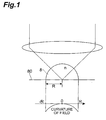
- Fig. 1 is a view showing an example of configuration and condition of use of a conventional solid immersion lens
- Fig. 2 is a view showing another example of configuration and condition of use of the conventional solid immersion lens
- Fig. 3 is a view showing the configuration and condition of use of a solid immersion lens employed in the sample observation method in accordance with the present invention
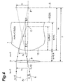
- Fig. 4 is a view showing a virtual optical system employed for evaluating geometric and chromatic aberration characteristics caused by the solid immersion lens shown in Fig. 3;
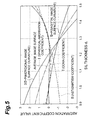
- Fig. 5 is a graph showing characteristics of the solid immersion lens evaluated by using the virtual optical system shown in Fig. 4;
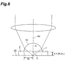
- Fig. 6 is a view showing another example of configuration and condition of use of the solid immersion lens employed in the sample observation method in accordance with the present invention.
- Fig. 7 is a view showing another embodiment of the solid immersion lens and sample observation method in accordance with the present invention.
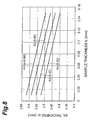
- Fig. 8 is a graph showing examples of the correlation between the thickness of a sample and the thickness of SIL
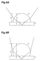
- Figs. 9A and 9B are side views showing the conversion of light in respective cases where the coefficient k is (A) smaller and (B) greater;
- Fig. 10 is a graph showing an example of the correlation between the value of coefficient k in SIL and the numerical aperture NA required for an objective lens;
- Fig. 11 is a graph showing an example of the correlation between the thickness of SIL + sample and the attained NA on the optical axis in the SIL.
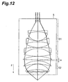
- Fig. 12 is a lateral sectional view showing the configuration of an objective lens.
- Fig. 1 is a view showing an example of the configuration and condition of use of the conventional SIL.
- the SIL 8 shown in Fig. 1 is a lens having a hemispherical form with a refractive index n and a radius of curvature R.
- the spherical center is a focal point, and a surface including the spherical center is set as a sample observation surface 80. Both the numerical aperture NA and magnitude in the sample observation are multiplied by n.
- a curvature of field occurs such that the image surface shifts downstream as being distanced farther from the focal point as shown in Fig. 1.
- Fig. 2 is a view showing another example of the configuration and condition of use of the conventional SIL.
- the SIL 9 shown in Fig. 2 is a lens having a hyperhemispherical form with a refractive index n and a radius of curvature R.
- n refractive index
- R radius of curvature
- a point located downstream of the spherical center by R/n along the optical axis is a focal point, and a surface including this point is set as a sample observation surface 90. Both the numerical aperture NA and magnitude in the sample observation are multiplied by n 2 .
- a curvature of field occurs such that the image surface shifts upstream in the direction opposite from that of Fig. 1 as being distanced farther from the focal point as shown in Fig. 2.
- the sample observation method using an SIL in accordance with the present invention observes an image of a sample by using a configuration and a condition of use of the SIL which are suitable for imaging according to the findings mentioned above.
- Fig. 3 is a view showing an embodiment of the sample observation method in accordance with the present invention, and the configuration and condition of use of the solid immersion lens used therefor.
- the sample observation method uses an SIL 1 formed from a material having a refractive index n L as a lens for enlarging a light image from a sample 2 to be observed.
- the SIL 1 is formed such that a spherical optical surface 10 having a radius of curvature R L about a point C as its spherical center is employed as a lens surface while an axis Ax acts as an optical axis.
- a point located downstream of the spherical center C of the spherical lens surface 10 by k ⁇ (R L /n L ) along the optical axis Ax is employed as a focal point.
- a surface 20 which includes this focal point and is substantially orthogonal to the optical axis Ax is observed with the SIL 1.
- the above coefficient k determining the focal point caused by the SIL 1 and the position of the sample observation surface 20 as seen from the spherical center C is a coefficient set so as to fall within the range of 0 ⁇ k ⁇ 1. Therefore, the focal point is located between the spherical center C and the point located downstream of the spherical center C by R L /n L along the optical axis.
- the coefficient k is set such that the SIL 1 yields a geometric aberration characteristic satisfying a predetermined condition.
- the magnification and curvature of field change successively between the spherical center C and the point located downstream of the spherical center C by R L /n L along the optical axis Ax.
- geometric aberration characteristics caused by the SIL 1 changes therein, etc. are evaluated.
- an appropriate coefficient k is set, and the focal point is selected thereby.
- the SIL 1 can be used under a condition in which the curvature of field is made smaller and the deterioration in aberration is sufficiently suppressed. This widens the field of view usable for observation, thereby making it possible to observe the image of the sample 2 favorably with the SIL 1.
- the sample observation surface 20 determined by the coefficient k coincides with a planar lens surface of the SIL 1 on the sample 2 side.
- Fig. 4 is a view showing a virtual optical system used for evaluating geometric and chromatic aberration characteristics caused by the SIL shown in Fig. 3.
- Fig. 5 is a graph showing characteristics of the SIL evaluated by using the virtual optical system shown in Fig. 4.
- n is the refractive index
- s is the distance from the object surface to a principal plane
- h is the height of a light beam.
- Overline bars indicate quantities concerning principal rays. In the specification, overlined “h 1 ", for example, will be referred to as “h - 1 ".
- a virtual optical system using the back focal plane of the SIL I as a pupil plane is introduced. Specifically, as shown in Fig. 4, a virtual objective lens 3 having no aberration is introduced so as to be placed at the back focal point F of the SIL 1.
- a focal length of this aberration-free virtual objective lens 3 is provided as fi, and a front focal position is provided as F'.
- the entrance pupil and the like are set as such, telecentricity is obtained inside the SIL 1, and thus can attain a form in conformity to an actual observation system for observing reflected light with laser scanning, etc. As a consequence, aberration and image surface characteristics caused by the SIL 1 can appropriately be evaluated.
- Fig. 4 illustrates two light beams l 1 , l 2 together with configurations of the SIL 1 and the optical system constructed by the virtual objective lens 3.
- the light beam l 1 passes a point on the optical axis Ax in a surface S' corresponding to the sample observation surface 20.
- the light beam l 1 passes a point F' on the optical axis Ax in the focal plane S of the virtual objective lens 3 as indicated by a dashed line.
- the light beam l 2 passes a point F on the optical axis Ax in the virtual objective lens 3, and yields a distance Y' from the optical axis Ax in the sample observation surface S'.
- the light beam l 2 yields a distance Y from the optical axis Ax in the focal plane S.
- Q 2 is the Abbe's invariant.
- Q 2 and J 2 are represented by the following expressions:
- Q 2 Q 2 h 2 / Q 2 h 2
- Fig. 5 is a graph showing the aberration coefficients of the spherical aberration coefficient I, coma coefficient II, astigmatism coefficient III, sagittal image surface curvature III+P, and meridional image surface curvature 3III+P determined by the above-mentioned expressions, respectively, and an average image surface of the sagittal image surface and meridional image surface.
- the curvature of field is generated in these points as mentioned above.
- the sagittal image surface curvature III+P is also zero.
- the astigmatism aberration coefficient III is also zero.
- the average image surface becomes flat at the point where the SIL has a thickness of 1.274 ⁇ R L , which is a calculation result totally different from that mentioned above.
- the solid immersion lens in accordance with the present invention and the sample observation method using the same are not limited to the embodiment mentioned above, but can be modified in various manners.
- the material for SIL is exemplified by silicon in the above-mentioned example, various materials other than silicon may be used according to materials of samples employed, observation conditions, etc.
- the refractive index of SIL is held constant at 3.5. This corresponds to a sample observation at a single wavelength, or a case where changes in refractive index caused by wavelength are negligible. Therefore, the condition where k is near 0.6 as mentioned above is effective when carrying out an observation, an inspection, or the like of the sample with light having a single wavelength.
- chromatic aberration is favorably balanced with other aberrations in the SIL made of silicon if k is about 0.3. It is thus preferred that the evaluation of image surface characteristics, the setting of coefficient k, etc. be carried out while taking account of the observation wavelength width if necessary.
- the coefficient k is set by the point at which the average image surface becomes flat.
- image surface characteristics caused by the SIL in the sample observation surface can favorably be set.
- the coefficient k may be set by a point within a predetermined condition range near the point where the average image surface becomes flat.
- the coefficient k may also be set by a point where the sagittal image surface or meridional image surface becomes flat instead of the average image surface.
- FIG. 3 shows a configuration in which the surface of the sample 2 becomes the sample observation surface 20
- the method of placing the SIL with respect to the sample is not limited thereto.
- FIG. 6 is a view showing another example of the configuration and condition of use of the solid immersion lens employed in the sample observation method in accordance with the present invention.
- the SIL 1 made of silicon is employed with respect to a silicon substrate 2 which is a sample
- the rear face of the substrate 2 is used as the sample observation surface 20.
- a predetermined part of the silicon substrate 2 functions as a downstream side part of the SIL 1, whereby an image of the sample can be observed as in the case where the front face is used as the sample observation surface 20.
- Such an observation method can be employed when inspecting a semiconductor device by a rear face observation, for example.
- Fig. 7 is a view showing another embodiment of the solid immersion lens and sample observation method in accordance with the present invention.
- an SIL 6 formed from a material having a refractive index n L is used as a lens for enlarging a light image from a sample 7 to be observed (e.g., semiconductor device).
- the SIL 6 is formed such that a spherical optical surface 60 having a radius of curvature R L about a point C as its spherical center is employed as a lens surface while an axis Ax acts as an optical axis.
- the coefficient k is set as in the embodiment of Fig. 3.
- the surface of the sample 7 opposite from the SIL 6 is employed as an observation surface 71 (e.g., a device surface of a semiconductor device).
- the SIL 6 is placed such that its flat lens surface on the sample 7 side is in close contact with the rear face 72 of the sample 7.
- the refractive index of the sample 7 is n S
- the thickness of the sample 7 is t S .
- the thickness t S is the thickness of the sample 7 from the rear face 72 to the observation surface 71, which is an actual observation surface with the SIL 6, along the optical axis Ax.
- the thickness of the SIL 6 along the optical axis Ax is d L ⁇ R L + k ⁇ (R L /n L ) in order to form a focal point on the observation surface 71 of the sample 7.
- a sample observation surface 70 which includes a point located downstream of the spherical center C of the lens surface 60 by k ⁇ (R L /n L ) along the optical axis Ax (0 ⁇ k ⁇ 1) and is substantially orthogonal to the optical axis Ax as mentioned above in connection with Fig. 3 is a virtual observation surface (an apparent observation surface determined from the lens form of the SIL 6) assuming that the refractive index of the sample 7 is identical to the refractive index n L of the SIL 6.
- the distance L corresponds to the focal length of the SIL 6 determined from the form of the lens surface 60.
- an optical path converging onto the actual observation surface 71 by way of the SIL 6 and sample 7 is indicated by solid lines.
- an optical path converging onto the virtual observation surface 70 assuming that the refractive index of the sample 7 is identical to that of the SIL 6 is indicated by dashed lines.
- the coefficient k is selected as in the embodiment shown in Fig. 3. In Fig.
- the thickness t S of the sample 7 is used as it is since the surface of the sample 7 on the side opposite from the SIL 6 is used as the observation surface 71.
- the observation surface is set within the sample 7, it will be sufficient if the thickness of the sample to the observation surface is used as t S .
- Fig. 8 is a graph showing examples of the correlation between the sample thickness and the SIL thickness.
- the abscissa indicates the thickness t S (mm) of the sample 7
- the ordinate indicates the thickness d L (mm) of the SIL 6.
- the thickness d L of the SIL 6 is set as in the examples shown in the graph of Fig. 8 according to their materials, values of coefficient k, etc.
- This enables observations under a condition where the solid immersion lens yields a substantially flat image surface characteristic.
- the observation with laser light from a monochromatic laser is free from the problem of chromatic aberration, whereby the coefficient k can be set so as to widen the field of view.
- Figs. 9A and 9B are side views showing the conversion of light when the coefficient k is (A) smaller and (B) greater, respectively.
- the coefficient k is set small, e.g., k is set so as to fall within the above-mentioned range of 0 ⁇ k ⁇ 0.5, the optical path of light as seen from the SIL becomes wider than that obtained when the coefficient k is greater as shown in Figs. 9A and 9B.
- Fig. 10 is a graph showing examples of correlation between the value of coefficient k in SIL and the numerical aperture NA required for an objective lens.
- the abscissa indicates the coefficient k set in the SIL, whereas the ordinate indicates the numerical aperture NA of the objective lens.
- Curves B1 and B2 represent the NAs required for the objective lens when the attained NA of the SIL on the optical axis is 3.0 and 2.5, respectively.
- the magnification in the SIL corresponding to the value of coefficient k is represented by curve B6.
- the NA required for the objective lens becomes greater as the attained NA in the SIL increases.
- the NA required for the objective lens increases as the value of coefficient k decreases as mentioned above in connection with Figs. 9A and 9B. Therefore, when setting the value of coefficient k in the SIL, its combination with the objective lens must be taken into consideration as well.
- Fig. 11 is a graph showing an example of correlation between the thickness of SIL + sample and the attained NA of SIL on the optical axis.
- the abscissa indicates the thickness (mm) of SIL + sample (Si substrate) from the vertex of SIL
- the ordinate indicates the attained NA of SIL on the optical axis.
- the NA of the objective lens is 0.76.
- Curves C1 and C2 represent attained NA when the material for SIL is Si and GaP, respectively. When the NA of the objective lens is held constant, the attained NA becomes greater as the thickness of SIL + sample increases.
- NAs of the SIL and objective lens are selected appropriately according to specific configurations.
- the attained NA in the SIL is on the order of 2.5 to 3.0, and the NA of the objective lens is about 0.76.
- the objective lens a normal objective lens can be used, whose magnification is about 50x, for example.
- the lens group of this objective lens 5 is constituted by two lens groups, i.e., a first lens group 51 and a second lens group 52, arranged along the optical axis.
- the gap u between the lens groups 51 and 52 can be changed by rotating a correction ring (not depicted) disposed on the outer peripheral part of the objective lens 5.
- the geometric aberration characteristic e.g., spherical aberration
- the coefficient k is preferably set within such a range that the spherical aberration in the SIL can be corrected by the correction ring in the objective lens.
- the coefficient k may be set within the range of 0.7 ⁇ k ⁇ 1.
- an objective lens having a lower NA can be combined therewith. Since a normal objective lens generates a large chromatic aberration, it is necessary to use a dedicatedly designed objective lens for purposes other than the monochromatic laser light.
- the solid immersion lens (SIL) in accordance with the present invention and the sample observation method using the same can be utilized as a sample observation method which can favorably observe an image of a sample with a solid immersion lens, and the solid immersion lens.
- the solid immersion lens and observation method in which the geometric aberration characteristic caused by the solid immersion lens is evaluated, the coefficient k (0 ⁇ k ⁇ 1) is set so as to satisfy a predetermined condition, and a surface which includes a point located downstream of the spherical center of the spherical optical surface of the solid immersion lens by k ⁇ (R L /n L ) along the optical axis and is substantially orthogonal to the optical axis is employed as a sample observation surface, can widen the field of view usable for observation, whereby the sample image can favorably be observed with the solid immersion lens.
- the lens form is set while taking account of the refractive index n S and thickness t S of the sample, a desirable observation part in the sample can favorably be observed:
Landscapes
- Physics & Mathematics (AREA)
- Chemical & Material Sciences (AREA)
- General Physics & Mathematics (AREA)
- Analytical Chemistry (AREA)
- Optics & Photonics (AREA)
- General Health & Medical Sciences (AREA)
- Health & Medical Sciences (AREA)
- Life Sciences & Earth Sciences (AREA)
- Biochemistry (AREA)
- Oil, Petroleum & Natural Gas (AREA)
- Immunology (AREA)
- Pathology (AREA)
- Engineering & Computer Science (AREA)
- Multimedia (AREA)
- Computer Vision & Pattern Recognition (AREA)
- Lenses (AREA)
- Investigating Or Analysing Materials By Optical Means (AREA)
- Microscoopes, Condenser (AREA)
Abstract
Description

Claims (10)
- A sample observation method using a solid immersion lens having a spherical optical surface with a radius of curvature RL formed from a material having a refractive index nL;
wherein the sample is observed with the solid immersion lens, while using as a sample observation surface a surface, substantially orthogonal to an optical axis, including a point located downstream of a spherical center of the optical surface by k × (RL/nL) along the optical axis, where k (0 < k < 1) is a coefficient set such that the solid immersion lens yields a geometric aberration characteristic satisfying a predetermined condition. - A sample observation method according to claim 1, wherein the solid immersion lens has a thickness of dL = RL + k × (RL/nL) along the optical axis; and
wherein the sample observation surface coincides with the sample-side lens surface of the solid immersion lens. - A sample observation method according to claim 1, wherein the solid immersion lens has a thickness of dL < RL + k × (RL/nL) along the optical axis, the sample observation surface being a virtual observation surface assuming that the sample has a refractive index equal to the refractive index nL of the solid immersion lens; and
wherein the thickness of the solid immersion lens satisfies dL = L - tS × (nL/nS) with respect to the length L = RL + k × (RL/nL) along the optical axis from a vertex to the virtual observation surface, where nS is the refractive index of the sample, and tS is the thickness of the sample to the actual observation surface. - A sample observation method according to any one of claims I to 3, wherein the geometric aberration characteristic is evaluated with a virtual optical system using a back focal plane of the solid immersion lens as a pupil plane, and the coefficient k is set according to a result of the evaluation.
- A sample observation method according to any one of claims 1 to 4, wherein the geometric aberration characteristic caused by the solid immersion lens is evaluated by a sagittal image surface, a meridional image surface, or an average image surface of the sagittal image surface and meridional image surface, and the coefficient k is set according to a result of the evaluation.
- A sample observation method according to any one of claims 1 to 5, wherein the coefficient k is a value within the range of 0.5 < k < 0.7.
- A sample observation method according to any one of claims 1 to 5, wherein the coefficient k is a value within the range of 0 < k ≤ 0.5.
- A solid immersion lens having a spherical optical surface with a radius of curvature RL formed from a material having a refractive index nL; wherein the distance along an optical axis from a vertex to a virtual observation surface assuming that a sample to be observed has a refractive index equal to the refractive index nL is L = RL + k × (RL/nL), where k (0 < k < 1) is a coefficient set such that the solid immersion lens yields a geometric aberration characteristic satisfying a predetermined condition; and
wherein the solid immersion lens has a thickness satisfying dL = L - tS × (nL/nS) along the optical axis, where nS is the refractive index of the sample, and tS is the thickness of the sample to an actual observation surface. - A solid immersion lens according to claim 8, wherein the coefficient k is a value within the range of 0.5 < k < 0.7.
- A solid immersion lens according to claim 8, wherein the coefficient k is a value within the range of 0 < k ≤ 0.5.
Applications Claiming Priority (5)
| Application Number | Priority Date | Filing Date | Title |
|---|---|---|---|
| JP2003078819 | 2003-03-20 | ||
| JP2003078819 | 2003-03-20 | ||
| JP2003146620 | 2003-05-23 | ||
| JP2003146620 | 2003-05-23 | ||
| PCT/JP2004/003734 WO2004088386A1 (en) | 2003-03-20 | 2004-03-19 | Solid immersion lens, and sample observing method using it |
Publications (2)
| Publication Number | Publication Date |
|---|---|
| EP1607784A1 true EP1607784A1 (en) | 2005-12-21 |
| EP1607784A4 EP1607784A4 (en) | 2011-05-04 |
Family
ID=33134271
Family Applications (1)
| Application Number | Title | Priority Date | Filing Date |
|---|---|---|---|
| EP04722019A Withdrawn EP1607784A4 (en) | 2003-03-20 | 2004-03-19 | Solid immersion lens, and sample observing method using it |
Country Status (6)
| Country | Link |
|---|---|
| US (2) | US7046449B2 (en) |
| EP (1) | EP1607784A4 (en) |
| JP (1) | JPWO2004088386A1 (en) |
| KR (1) | KR101074628B1 (en) |
| TW (1) | TWI336777B (en) |
| WO (1) | WO2004088386A1 (en) |
Families Citing this family (11)
| Publication number | Priority date | Publication date | Assignee | Title |
|---|---|---|---|---|
| US7312921B2 (en) * | 2004-02-27 | 2007-12-25 | Hamamatsu Photonics K.K. | Microscope and sample observation method |
| JP4643994B2 (en) * | 2005-01-19 | 2011-03-02 | 浜松ホトニクス株式会社 | Solid immersion lens holder |
| CN101126491B (en) * | 2006-08-18 | 2011-03-23 | 鸿富锦精密工业(深圳)有限公司 | LED module group |
| JP5364452B2 (en) | 2009-06-03 | 2013-12-11 | 浜松ホトニクス株式会社 | Immersion lens support device |
| US8767199B2 (en) | 2010-10-15 | 2014-07-01 | Infrared Laboratories, Inc. | Inspection system utilizing solid immersion lenses |
| WO2013031141A1 (en) * | 2011-08-29 | 2013-03-07 | パナソニック株式会社 | Molecule detecting apparatus, molecule detecting method, and cartridge for detecting molecules |
| DE102013203628B4 (en) * | 2013-03-04 | 2020-06-10 | Leica Microsystems Cms Gmbh | Immersion objective for microscopes and its use |
| JP6525161B2 (en) * | 2013-04-12 | 2019-06-05 | デイライト ソリューションズ、インコーポレイテッド | Refractive objective lens assembly for infrared light |
| KR20160013931A (en) | 2013-05-23 | 2016-02-05 | 어플라이드 머티리얼즈 이스라엘 리미티드 | An evaluation system and a method for evaluating a substrate |
| GB201704275D0 (en) * | 2017-03-17 | 2017-05-03 | Science And Tech Facilities Council | Super-resolution microscopy |
| JP2020020994A (en) * | 2018-08-02 | 2020-02-06 | 浜松ホトニクス株式会社 | Solid immersion lens unit and semiconductor inspection device |
Family Cites Families (26)
| Publication number | Priority date | Publication date | Assignee | Title |
|---|---|---|---|---|
| US5004307A (en) * | 1990-04-12 | 1991-04-02 | The Board Of Trustees Of The Leland Stanford Junior University | Near field and solid immersion optical microscope |
| US5220403A (en) * | 1991-03-11 | 1993-06-15 | International Business Machines Corporation | Apparatus and a method for high numerical aperture microscopic examination of materials |
| US5208648A (en) * | 1991-03-11 | 1993-05-04 | International Business Machines Corporation | Apparatus and a method for high numerical aperture microscopic examination of materials |
| US5125750A (en) * | 1991-03-14 | 1992-06-30 | The Board Of Trustees Of The Leland Stanford Junior University | Optical recording system employing a solid immersion lens |
| JPH0718806A (en) | 1993-07-02 | 1995-01-20 | Sekisui Chem Co Ltd | Outdoor step structure |
| JPH08315404A (en) | 1995-05-18 | 1996-11-29 | Sony Corp | Optical pickup device |
| EP0977192A4 (en) | 1997-04-14 | 2000-11-15 | Toray Industries | Optical recording device and optical recording medium |
| JPH113534A (en) | 1997-04-14 | 1999-01-06 | Toray Ind Inc | Optical recording device and optical recording medium |
| US5939709A (en) | 1997-06-19 | 1999-08-17 | Ghislain; Lucien P. | Scanning probe optical microscope using a solid immersion lens |
| JPH11203711A (en) * | 1998-01-08 | 1999-07-30 | Canon Inc | High numerical aperture optical system and optical information recording / reproducing apparatus using the same |
| JPH11202194A (en) * | 1998-01-16 | 1999-07-30 | Canon Inc | High numerical aperture optical system and optical information recording / reproducing apparatus using the same |
| JP2000011423A (en) * | 1998-06-23 | 2000-01-14 | Canon Inc | Information recording / reproducing optical system |
| JP3972484B2 (en) * | 1998-09-16 | 2007-09-05 | コニカミノルタオプト株式会社 | Solid immersion lens |
| JP2000121930A (en) | 1998-10-14 | 2000-04-28 | Nikon Corp | Imaging optical system using solid immersion lens, optical disk recording / reproducing apparatus and microscope using this imaging optical system |
| US6441359B1 (en) * | 1998-10-20 | 2002-08-27 | The Board Of Trustees Of The Leland Stanford Junior University | Near field optical scanning system employing microfabricated solid immersion lens |
| JP3997029B2 (en) | 1999-02-15 | 2007-10-24 | キヤノン株式会社 | Probe for light detection or light irradiation and manufacturing method thereof |
| US6687058B1 (en) * | 1999-06-21 | 2004-02-03 | The Trustees Of Boston University | Numerical aperature increasing lens (nail) techniques for high-resolution sub-surface imaging |
| JP2001023230A (en) | 1999-07-12 | 2001-01-26 | Nikon Corp | Optical head and optical recording / reproducing device |
| US6301055B1 (en) * | 2000-08-16 | 2001-10-09 | California Institute Of Technology | Solid immersion lens structures and methods for producing solid immersion lens structures |
| JP3602465B2 (en) * | 2000-10-10 | 2004-12-15 | Necエレクトロニクス株式会社 | Semiconductor device, semiconductor device evaluation analysis method, and semiconductor device processing apparatus |
| JP3840957B2 (en) * | 2001-01-24 | 2006-11-01 | 株式会社村田製作所 | Non-reciprocal circuit device and communication device |
| JP2002236087A (en) | 2001-02-08 | 2002-08-23 | Minolta Co Ltd | Optical system adjustment method, and optical recording / reproducing apparatus, microscope apparatus, and processing apparatus using the optical system adjustment method |
| US6621275B2 (en) * | 2001-11-28 | 2003-09-16 | Optonics Inc. | Time resolved non-invasive diagnostics system |
| US6594086B1 (en) * | 2002-01-16 | 2003-07-15 | Optonics, Inc. (A Credence Company) | Bi-convex solid immersion lens |
| US6683724B2 (en) * | 2002-06-13 | 2004-01-27 | Eastman Kodak Company | Solid immersion lens array and methods for producing a solid immersion lens array |
| WO2004003891A1 (en) * | 2002-06-28 | 2004-01-08 | Seagate Technology Llc | Heat assisted magnetic recording head with a planar waveguide |
-
2004
- 2004-03-19 JP JP2005504163A patent/JPWO2004088386A1/en active Pending
- 2004-03-19 US US10/804,193 patent/US7046449B2/en not_active Expired - Lifetime
- 2004-03-19 TW TW093107467A patent/TWI336777B/en not_active IP Right Cessation
- 2004-03-19 WO PCT/JP2004/003734 patent/WO2004088386A1/en not_active Ceased
- 2004-03-19 KR KR1020057017613A patent/KR101074628B1/en not_active Expired - Lifetime
- 2004-03-19 EP EP04722019A patent/EP1607784A4/en not_active Withdrawn
-
2005
- 2005-11-03 US US11/265,496 patent/US7149036B2/en not_active Expired - Lifetime
Also Published As
| Publication number | Publication date |
|---|---|
| US7046449B2 (en) | 2006-05-16 |
| KR20050112106A (en) | 2005-11-29 |
| WO2004088386A1 (en) | 2004-10-14 |
| TW200506340A (en) | 2005-02-16 |
| KR101074628B1 (en) | 2011-10-17 |
| US20060109562A1 (en) | 2006-05-25 |
| US20040240075A1 (en) | 2004-12-02 |
| EP1607784A4 (en) | 2011-05-04 |
| US7149036B2 (en) | 2006-12-12 |
| JPWO2004088386A1 (en) | 2006-07-06 |
| TWI336777B (en) | 2011-02-01 |
Similar Documents
| Publication | Publication Date | Title |
|---|---|---|
| US7046449B2 (en) | Solid immersion lens and sample observation method using it | |
| JP5479206B2 (en) | Catadioptric optical system and imaging apparatus having the same | |
| JPH08286113A (en) | Objective lens | |
| JP4066079B2 (en) | Objective lens and optical apparatus using the same | |
| KR101387823B1 (en) | Catadioptric system and image pickup apparatus | |
| JP3724520B2 (en) | Infrared optics | |
| JP3126028B2 (en) | High magnification objective lens | |
| JPH10288740A (en) | Long working distance microscope objective | |
| JP5868063B2 (en) | Imaging device | |
| US4753523A (en) | Low magnification projection objective lens | |
| US7869121B2 (en) | Small ultra-high NA catadioptric objective using aspheric surfaces | |
| US8947773B2 (en) | Catadioptric optical element and optical system including same | |
| JP5656682B2 (en) | Catadioptric optical system and imaging apparatus having the same | |
| US10884229B2 (en) | Immersion microscope objective | |
| JP4059644B2 (en) | Observation optical system | |
| JP2015036706A (en) | Imaging device | |
| US20040109238A1 (en) | Optical arrangement for microscope objective | |
| JP2001305431A (en) | Objective lens | |
| JP2015036706A5 (en) | ||
| JP5627476B2 (en) | Catadioptric optical system and imaging apparatus having the same | |
| US11402619B2 (en) | Immersion microscope objective | |
| JP2000241710A (en) | Microscope objective lens | |
| JP2015184544A (en) | Catadioptric optical system and imaging apparatus having the same | |
| JP2000249926A (en) | Microscope objective lens and microscope | |
| JPH09101462A (en) | Microscope objective lens |
Legal Events
| Date | Code | Title | Description |
|---|---|---|---|
| PUAI | Public reference made under article 153(3) epc to a published international application that has entered the european phase |
Free format text: ORIGINAL CODE: 0009012 |
|
| 17P | Request for examination filed |
Effective date: 20051004 |
|
| AK | Designated contracting states |
Kind code of ref document: A1 Designated state(s): AT BE BG CH CY CZ DE DK EE ES FI FR GB GR HU IE IT LI LU MC NL PL PT RO SE SI SK TR |
|
| AX | Request for extension of the european patent |
Extension state: AL LT LV MK |
|
| DAX | Request for extension of the european patent (deleted) | ||
| RBV | Designated contracting states (corrected) |
Designated state(s): DE FR |
|
| A4 | Supplementary search report drawn up and despatched |
Effective date: 20110406 |
|
| 17Q | First examination report despatched |
Effective date: 20110923 |
|
| STAA | Information on the status of an ep patent application or granted ep patent |
Free format text: STATUS: THE APPLICATION IS DEEMED TO BE WITHDRAWN |
|
| 18D | Application deemed to be withdrawn |
Effective date: 20120404 |