EP1607721A2 - Signal processing apparatus and method of differential transformer - Google Patents
Signal processing apparatus and method of differential transformer Download PDFInfo
- Publication number
- EP1607721A2 EP1607721A2 EP05253176A EP05253176A EP1607721A2 EP 1607721 A2 EP1607721 A2 EP 1607721A2 EP 05253176 A EP05253176 A EP 05253176A EP 05253176 A EP05253176 A EP 05253176A EP 1607721 A2 EP1607721 A2 EP 1607721A2
- Authority
- EP
- European Patent Office
- Prior art keywords
- frequency
- signal
- output
- differential transformer
- pass filter
- Prior art date
- Legal status (The legal status is an assumption and is not a legal conclusion. Google has not performed a legal analysis and makes no representation as to the accuracy of the status listed.)
- Granted
Links
Images




Classifications
-
- G—PHYSICS
- G01—MEASURING; TESTING
- G01D—MEASURING NOT SPECIALLY ADAPTED FOR A SPECIFIC VARIABLE; ARRANGEMENTS FOR MEASURING TWO OR MORE VARIABLES NOT COVERED IN A SINGLE OTHER SUBCLASS; TARIFF METERING APPARATUS; MEASURING OR TESTING NOT OTHERWISE PROVIDED FOR
- G01D5/00—Mechanical means for transferring the output of a sensing member; Means for converting the output of a sensing member to another variable where the form or nature of the sensing member does not constrain the means for converting; Transducers not specially adapted for a specific variable
- G01D5/12—Mechanical means for transferring the output of a sensing member; Means for converting the output of a sensing member to another variable where the form or nature of the sensing member does not constrain the means for converting; Transducers not specially adapted for a specific variable using electric or magnetic means
- G01D5/14—Mechanical means for transferring the output of a sensing member; Means for converting the output of a sensing member to another variable where the form or nature of the sensing member does not constrain the means for converting; Transducers not specially adapted for a specific variable using electric or magnetic means influencing the magnitude of a current or voltage
- G01D5/20—Mechanical means for transferring the output of a sensing member; Means for converting the output of a sensing member to another variable where the form or nature of the sensing member does not constrain the means for converting; Transducers not specially adapted for a specific variable using electric or magnetic means influencing the magnitude of a current or voltage by varying inductance, e.g. by a movable armature
- G01D5/22—Mechanical means for transferring the output of a sensing member; Means for converting the output of a sensing member to another variable where the form or nature of the sensing member does not constrain the means for converting; Transducers not specially adapted for a specific variable using electric or magnetic means influencing the magnitude of a current or voltage by varying inductance, e.g. by a movable armature differentially influencing two coils
- G01D5/2291—Linear or rotary variable differential transformers (LVDTs/RVDTs) having a single primary coil and two secondary coils
Definitions
- the present invention relates to a signal processing apparatus and method of a differential transformer for obtaining a measurement signal having a fast response speed from a differential transformer having a low excitation frequency. More particularly, the present invention relates to a signal processing apparatus and method of a differential transformer suitably employed in a high-resolution electric micrometer having a resolution of approximately 1 nm, in which the response speed of a measurement signal can be increased by a factor of 10 to 100 (200 Hz to 2 kHz) with the use of a conventional head having an excitation frequency of approximately 5 kHz.
- a conventional electric micrometer has been configured as disclosed in Japanese Patent Laid-Open Publication No. 2002-340505.
- the electric micrometer includes, as shown in Fig. 1, the displacement of a spindle 22 which is a part of a head 20 is transferred to a core 26, and sensor coils 28 and 30 are placed symmetrically with respect to the mechanical center point (neutral point) of the core 26 and are connected each other in series to form a differential transformer.
- a voltage is applied to the sensor coils 28 and 30 through an external oscillator 32, voltages E1 and E2 are generated at the ends of the sensor coils 28 and 30, respectively, as shown in Fig. 2 due to the impedance change of the sensor coils 28 and 30 according to the position of the core 26.
- the displacement of the spindle 22 is detected through the voltage difference (E1-E2) based on the change in the position of the core 26.
- a sine-wave driving signal having a frequency of, for example, 5 kHz generated in the oscillator 32 is applied to the sensor coils 28 and 30 (not shown in Fig. 3) of the head (cartridge head or lever head) 20 via a driving amplifier 34.
- the output signal obtained from the neutral point of the sensor coils 28 and 30 is amplified by a preamplifier 36, and the amplified signal is half-wave or full-wave rectified by means of a synchronous detector 38 in synchronization with the excitation signal generated by the oscillator 32.
- the 5 kHz component of the rectified signal is removed by a low-pass filter (LPF) 40, and the filtered analog signal is then displayed on a meter.
- LPF low-pass filter
- the filtered analog signal is converted into a digital signal by means of an analog-digital (A/D) converter 42, and the converted digital signal is digitally processed by a microprocessor 44 to digitally display.
- A/D analog-digital
- the digital data output signal output from the microprocessor 44 is subjected to processing by means of, for example, a parallel-serial converter, a shift register, a gate, a communication driver, and the like in accordance with need.
- the electronic micrometer is composed of the differential transformer (inductor), the balance adjustment for the capacitance component and also for the inductance component cannot be made with the use of a resistor. Therefore, the signal at the reference position cannot be accurately adjusted to zero.
- the excitation frequency cannot be increased due to the characteristics of the head 20, for example, it is at most 5 kHz. Therefore, a ripple component having a frequency of 5 kHz and generated at the synchronous detector 38 remains in the subsequent stages of the circuit. Therefore, the LPF 40 having a low cut-off frequency must be provided after the synchronous detector 38. However, this causes a reduction in the response speed (for example, approximately 20 Hz (-3 dB) in a low-end product having a resolution of 0.1 ⁇ m). Further, in a high-precision electronic micrometer which requires a resolution of approximately 1 nm, the response speed becomes much slower (several hundred milliseconds (several Hz)).
- various exemplary embodiments of this invention provide a measurement signal with a fast response speed from a differential transformer having a low excitation frequency.
- a signal processing apparatus of a differential transformer for obtaining a measurement signal with a fast response speed from a differential transformer having a low excitation frequency.
- the signal processing apparatus comprises: a high-frequency oscillator which generates a high-frequency signal having a frequency higherthan the excitation frequency of the differential transformer; a frequency divider which divides the high-frequency signal to generate a driving signal for the differential transformer; frequency reduction means which reduces the frequency of the high-frequency signal by the frequency of the driving signal; a mixer which mixes an output from the frequency reduction means with an output from the differential transformer; a high-pass filter or a band-pass filter which cuts a low-frequency component of an output from the mixer; and means which synchronously detects the output from the high-pass filter or the band-pass filter with the use of the high-frequency signal.
- the signal processing apparatus further comprises: a first PLL circuit which extracts and holds a frequency component of the output from the frequency reduction means; and a first phase shifter which matches a phase of the output from the frequency reduction means to a phase of the output from the differential transformer. This ensures that the phase of the output from the frequency reduction means is matched to the phase of the output from the differential transformer.
- the signal processing apparatus further comprises: a second PLL circuit which extracts and holds a frequency component of an output from the high-pass filter or the band-pass filter; and a second phase shifter which matches the phase of the high-frequency signal to a phase of an output from the high-pass filter or the band-pass filter. This ensures that the phase of the high-frequency signal is matched to the phase of the output from the high-pass filter.
- a signal processing method of a differential transformer for obtaining a measurement signal with a fast response speed from a differential transformer having a low excitation frequency, the method comprising the steps of: generating a high-frequency signal having a frequency higher than the excitation frequency of the differential transformer; dividing the high-frequency signal to generate a driving signal for the differential transformer; reducing the frequency of the high-frequency signal by the frequency of the driving signal; mixing the frequency reduced signal with an output from the differential transformer; cutting a low-frequency component of the mixed signal; and detecting the low-frequency cut signal with the use of the high-frequency signal.
- a measurement signal with a fast response speed can be obtained from a differential transformer having a low excitation frequency. Therefore, the response speed can be increased by a factor of 10 to 100 through the use of an electric circuit without modifying the existing head.
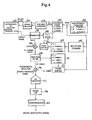
- the electric micrometer of a first exemplary embodiment of the present invention comprises, as in the conventional electric micrometer, a cartridge head or lever head (hereinafter referred to simply as a head) 20 with an excitation frequency of 5 kHz, a driving amplifier 34, a preamplifier 36, an A/D converter 42, and a microprocessor 44.
- the electric micrometer further comprises: a high-frequency (carrierwave) oscillator 50; a frequency divider 52; a sine-wave converter 54; a phase-locked loop (PLL) circuit 56; a multiplier (or divider) 60; a first PLL circuit 62; a first phase shifter 64; a mixer 66; a high-pass filter (HPF) 68; a second PLL circuit 70; a second phase shifter 72; a double balanced mixer 74; and an LPF 76.
- a high-frequency (carrierwave) oscillator 50 a frequency divider 52; a sine-wave converter 54; a phase-locked loop (PLL) circuit 56; a multiplier (or divider) 60; a first PLL circuit 62; a first phase shifter 64; a mixer 66; a high-pass filter (HPF) 68; a second PLL circuit 70; a second phase shifter 72; a double balanced mixer 74; and an LPF 76.
- carrierwave
- the high-frequency (carrierwave) oscillator 50 generates a rectangular shaped high frequency (carrierwave) signal having a radio frequency (for example, 2.56 MHz, 5.12 MHz, or 10.24 MHz) higher than the excitation frequency of the head 20 (5 kHz) by a factor of 500 to several thousand.
- a radio frequency for example, 2.56 MHz, 5.12 MHz, or 10.24 MHz
- the frequency divider 52 divides the high-frequency signal output from the high-frequency oscillator 50 (for example, by a factor of 1/512, 1/1024, or 1/2048) to obtain a signal having a frequency of 5 kHz (the excitation frequency of the head 20).
- the sine-wave converter 54 converts the rectangular wave signal output from the frequency divider 52 to a sine-wave signal to obtain a driving signal to be input to the driving amplifier 34 as in the conventional electric micrometer.
- the PLL circuit 56 extracts and holds a component with the same frequency as the excitation frequency (5 kHz) from the output of the preamplifier 36 as in the conventional electric micrometer.
- the multiplier (or divider) 60 serves as frequency reduction means which reduces the high frequency signal output from the high-frequency oscillator 50 by the excitation frequency.
- the first PLL circuit 62 accurately generates a signal having a frequency of 2.555 MHz, 5.115 MHz, or 10.235 MHz from the output of the multiplier 60.
- the first phase shifter 64 matches the phase of the output from the multiplier 60 via the first PLL circuit 62 to the phase of the output from the preamplifier 36.
- the mixer 66 mixes and modulates the output from the preamplifier 36 and the output from the first phase shifter 64.
- the HPF 68 cuts a component having a lower frequency (for example, 10.23 MHz) from the output of the mixer 66 (if the frequency of the high-frequency signal is 10.24 MHz, the frequencies of the output are 10.235 plus or minus 5 kHz) and passes a component having a higher frequency (for example, 10.24 MHz).
- a lower frequency for example, 10.23 MHz
- the frequencies of the output are 10.235 plus or minus 5 kHz
- the second PLL circuit 70 extracts and holds a component having a frequency of 2.56 MHz, 5.12 MHz, or 10.24 MHz output from the HPF 68.
- the second phase shifter 72 shifts the phase of the output from the high-frequency oscillator 50 according to the output from the second PLL circuit 70.
- the double balanced mixer 74 detects the output from the HPF 68 in synchronization with the output from the second phase shifter 72.
- the LPF 76 such as a digital LPF which is smaller than a conventional LPF passes a low-frequency component of the signal output from the double balanced mixer 74.
- the LPF 76 is provided at the output side of the A/D converter 42.
- the digital LPF 76 may be replaced with an analog filter provided before the A/D converter 42.
- the response speed can be increased through mixing a high-frequency signal to the output from the conventional head 20.
- the signal can be easily divided by the frequency divider 52 since the high-frequency oscillator 50 can generate a rectangular-shaped wave. No particular limitation is imposed on the method of dividing the output from the high-frequency oscillator 50.
- the sine-wave converter 54 may be omitted if a high-frequency oscillator generating a sine wave is employed.
- the phases of the signals can be accurately matched with each other since the first phase shifter 64 together with the first PLL circuit 62 and the second phase shifter 72 together with the second PLL circuit 70 are provided.
- One or both of the phase shifters may be omitted depending on performance specifications.
- the PLL circuit 56 of the first exemplary embodiment is omitted to deliver a signal with a frequency of 5 kHz from the frequency divider 52 to the first phase shifter 64.
- the high-pass filter 68 may be replaced with a band-pass filter or may be combined with a notch filter or a band-pass filter matched to the target frequency. It is preferred to adopt a band-pass filter having steep notch characteristics to increase the S/N ratio.
- the present invention has been applied to an electric micrometer, but the present invention may also be applied to other electric microproducts and other general measuring apparatus employing a differential transformer.
Landscapes
- Engineering & Computer Science (AREA)
- Power Engineering (AREA)
- Physics & Mathematics (AREA)
- General Physics & Mathematics (AREA)
- Measurement Of Length, Angles, Or The Like Using Electric Or Magnetic Means (AREA)
- Transmission And Conversion Of Sensor Element Output (AREA)
Abstract
Description
Claims (8)
- A signal processing apparatus of a differential transformer for obtaining a measurement signal with a fast response speed from a differential transformer having a low excitation frequency, the apparatus comprising:a high-frequency oscillator which generates a high-frequency signal having a frequency higher than the excitation frequency of the differential transformer;a frequency divider which divides the high-frequency signal to generate a driving signal for the differential transformer;frequency reduction means which reduces the frequency of the high-frequency signal by the frequency of the driving signal;a mixer which mixes an output from the frequency reduction means with an output from the differential transformer;a high-pass filter or a band-pass filter which cuts a low-frequency component of an output from the mixer; andmeans which synchronously detects the output from the high-pass filter or the band-pass filter with the use of the high-frequency signal.
- The signal processing apparatus of a differential transformer according to claim 1, further comprising:a first PLL circuit which extracts and holds a frequency component of the output from the frequency reduction means; anda first phase shifter which matches a phase of the output from the frequency reduction means to a phase of the output from the differential transformer.
- The signal processing apparatus of a differential transformer according to claim 1 or 2, further comprising:a second PLL circuit which extracts and holds a frequency component of an output from the high-pass filter or the band-pass filter; anda second phase shifter which matches the phase of the high-frequency signal to a phase of an output from the high-pass filter or the band-pass filter.
- Apparatus according to any of the preceding claims, wherein the high-frequency oscillator outputs a rectangular shaped wave.
- Apparatus according to any of claims 1 to 3, wherein the high-frequency oscillator outputs a sine wave.
- Apparatus according to any of the preceding claims, wherein the frequency reduction means is a multiplier or a divider.
- Apparatus according to any of the preceding claims, wherein the means which synchronously detects the output is a double balanced mixer.
- A signal processing method of a differential transformer for obtaining a measurement signal with a fast response speed from a differential transformer having a low excitation frequency, the method comprising the steps of:generating a high-frequency signal having a frequency higher than the excitation frequency of the differential transformer;dividing the high-frequency signal to generate a driving signal for the differential transformer;reducing the frequency of the high-frequency signal by the frequency of the driving signal;mixing the frequency reduced signal with an output from the differential transformer;cutting a low-frequency component of the mixed signal; anddetecting the low-frequency cut signal with the use of the high-frequency signal.
Applications Claiming Priority (4)
| Application Number | Priority Date | Filing Date | Title |
|---|---|---|---|
| JP2004153115 | 2004-05-24 | ||
| JP2004153115 | 2004-05-24 | ||
| JP2005141294A JP4690110B2 (en) | 2004-05-24 | 2005-05-13 | Differential transformer signal processing apparatus and signal processing method |
| JP2005141294 | 2005-05-13 |
Publications (3)
| Publication Number | Publication Date |
|---|---|
| EP1607721A2 true EP1607721A2 (en) | 2005-12-21 |
| EP1607721A3 EP1607721A3 (en) | 2007-01-03 |
| EP1607721B1 EP1607721B1 (en) | 2008-05-07 |
Family
ID=35159724
Family Applications (1)
| Application Number | Title | Priority Date | Filing Date |
|---|---|---|---|
| EP05253176A Ceased EP1607721B1 (en) | 2004-05-24 | 2005-05-24 | Signal processing apparatus and method of differential transformer |
Country Status (4)
| Country | Link |
|---|---|
| US (1) | US7395044B2 (en) |
| EP (1) | EP1607721B1 (en) |
| JP (1) | JP4690110B2 (en) |
| DE (1) | DE602005006470D1 (en) |
Families Citing this family (5)
| Publication number | Priority date | Publication date | Assignee | Title |
|---|---|---|---|---|
| US8963735B2 (en) | 2011-11-30 | 2015-02-24 | Rosemount Inc. | Turbine meter pre-scaling terminal block electronics |
| US9528815B2 (en) | 2013-02-08 | 2016-12-27 | Hamilton Sundstrand Corporation | Transformer based sensor arrangement |
| US9448275B2 (en) | 2013-06-25 | 2016-09-20 | The Boeing Company | Fault detection of four wire variable differential transformer sensors |
| JP6770300B2 (en) | 2015-09-29 | 2020-10-14 | 株式会社ミツトヨ | Signal processing circuit for measuring equipment |
| US10345357B2 (en) | 2016-02-29 | 2019-07-09 | The Boeing Company | Fault detection in variable differential transformer sensors based on zero-crossings of signals |
Family Cites Families (12)
| Publication number | Priority date | Publication date | Assignee | Title |
|---|---|---|---|---|
| JPS56143923A (en) | 1980-04-10 | 1981-11-10 | Noble Sangyo Kk | Vibrometer |
| JPS589019A (en) | 1981-07-10 | 1983-01-19 | Hitachi Ltd | Displacement speed detection device |
| FR2656087B1 (en) * | 1989-12-14 | 1992-03-13 | Commissariat Energie Atomique | INDUCTIVE SENSOR AND DEVICES FOR MEASURING THE MOVEMENT OF A MOBILE MEMBER. |
| JPH0797009B2 (en) * | 1989-12-29 | 1995-10-18 | 株式会社荏原製作所 | Inductance type displacement sensor |
| US6208875B1 (en) * | 1998-04-08 | 2001-03-27 | Conexant Systems, Inc. | RF architecture for cellular dual-band telephones |
| CA2401182A1 (en) * | 2000-02-28 | 2001-09-07 | Chandra Mohan | A novel low cost/low power analog transceiver architecture |
| US6882680B1 (en) * | 2000-06-09 | 2005-04-19 | Umbrella Capital, Llc | Quadrature phase modulation receiver for spread spectrum communications system |
| US6856794B1 (en) * | 2000-07-27 | 2005-02-15 | Sirf Technology, Inc. | Monolithic GPS RF front end integrated circuit |
| JP2002271241A (en) * | 2001-03-06 | 2002-09-20 | Matsushita Electric Ind Co Ltd | Relay device |
| JP3929256B2 (en) * | 2001-05-21 | 2007-06-13 | 株式会社ミツトヨ | Differential transformer signal processing device |
| US6753686B2 (en) | 2001-05-21 | 2004-06-22 | Mitutoyo Corporation | Method and apparatus for detecting failure of differential transformer, and method and apparatus for signal processing of differential transformer |
| US7006938B2 (en) * | 2004-06-16 | 2006-02-28 | Ami Semiconductor, Inc. | Reactive sensor modules using Pade' Approximant based compensation and providing module-sourced excitation |
-
2005
- 2005-05-13 JP JP2005141294A patent/JP4690110B2/en not_active Expired - Fee Related
- 2005-05-20 US US11/133,352 patent/US7395044B2/en active Active
- 2005-05-24 EP EP05253176A patent/EP1607721B1/en not_active Ceased
- 2005-05-24 DE DE602005006470T patent/DE602005006470D1/en not_active Expired - Lifetime
Also Published As
| Publication number | Publication date |
|---|---|
| JP2006010680A (en) | 2006-01-12 |
| US7395044B2 (en) | 2008-07-01 |
| US20050258817A1 (en) | 2005-11-24 |
| DE602005006470D1 (en) | 2008-06-19 |
| EP1607721A3 (en) | 2007-01-03 |
| EP1607721B1 (en) | 2008-05-07 |
| JP4690110B2 (en) | 2011-06-01 |
Similar Documents
| Publication | Publication Date | Title |
|---|---|---|
| JP3047231B1 (en) | Resolver | |
| JP3018197B2 (en) | Magnetic resonance imaging system | |
| US10955262B2 (en) | Rotation angle sensor for a stator | |
| JPH1172515A (en) | Broadband analog isolation circuit | |
| US7629795B2 (en) | Vector impedance measurement system and method of using same | |
| US20170268907A1 (en) | Inductive position sensor with frequency converter and goertzel filter for analyzing signals | |
| US6672159B2 (en) | Method for adjusting the phase-locking loop of an electronic evaluation device and corresponding electronic evaluation device | |
| EP1607721B1 (en) | Signal processing apparatus and method of differential transformer | |
| JPH0797009B2 (en) | Inductance type displacement sensor | |
| JP3761111B2 (en) | Angular velocity measuring device and angular velocity measuring method | |
| JP4126434B2 (en) | Improved method and apparatus for detecting resonant frequencies | |
| JP2008289153A (en) | Converter | |
| US20060207347A1 (en) | Arrangement for measuring the torque of rotating machine parts | |
| CN1120566C (en) | Frequency hopping and pilot frequency technology using for control sytsem for distortion generated from reducing circuit | |
| JP3346087B2 (en) | Magnetometer | |
| JPH06229852A (en) | Force detector | |
| JP3879579B2 (en) | Moisture sensor | |
| WO2007013302A1 (en) | Frequency component measuring device | |
| JP3929256B2 (en) | Differential transformer signal processing device | |
| JP3078391B2 (en) | Position detection device | |
| EP4707745A1 (en) | Inductive position sensor | |
| JPH0961506A (en) | Magnetic sensor circuit | |
| JPH11173872A (en) | Linear resolver signal generation method and linear resolver | |
| CN1702426A (en) | Signal processing apparatus and method of differential transformer | |
| JP2001289608A (en) | Rotation angle detector |
Legal Events
| Date | Code | Title | Description |
|---|---|---|---|
| PUAI | Public reference made under article 153(3) epc to a published international application that has entered the european phase |
Free format text: ORIGINAL CODE: 0009012 |
|
| AK | Designated contracting states |
Kind code of ref document: A2 Designated state(s): AT BE BG CH CY CZ DE DK EE ES FI FR GB GR HU IE IS IT LI LT LU MC NL PL PT RO SE SI SK TR |
|
| AX | Request for extension of the european patent |
Extension state: AL BA HR LV MK YU |
|
| PUAL | Search report despatched |
Free format text: ORIGINAL CODE: 0009013 |
|
| AK | Designated contracting states |
Kind code of ref document: A3 Designated state(s): AT BE BG CH CY CZ DE DK EE ES FI FR GB GR HU IE IS IT LI LT LU MC NL PL PT RO SE SI SK TR |
|
| AX | Request for extension of the european patent |
Extension state: AL BA HR LV MK YU |
|
| 17P | Request for examination filed |
Effective date: 20070129 |
|
| AKX | Designation fees paid |
Designated state(s): DE FR GB IT |
|
| 17Q | First examination report despatched |
Effective date: 20071015 |
|
| GRAP | Despatch of communication of intention to grant a patent |
Free format text: ORIGINAL CODE: EPIDOSNIGR1 |
|
| GRAS | Grant fee paid |
Free format text: ORIGINAL CODE: EPIDOSNIGR3 |
|
| GRAA | (expected) grant |
Free format text: ORIGINAL CODE: 0009210 |
|
| AK | Designated contracting states |
Kind code of ref document: B1 Designated state(s): DE FR GB IT |
|
| REG | Reference to a national code |
Ref country code: GB Ref legal event code: FG4D |
|
| REF | Corresponds to: |
Ref document number: 602005006470 Country of ref document: DE Date of ref document: 20080619 Kind code of ref document: P |
|
| PLBE | No opposition filed within time limit |
Free format text: ORIGINAL CODE: 0009261 |
|
| STAA | Information on the status of an ep patent application or granted ep patent |
Free format text: STATUS: NO OPPOSITION FILED WITHIN TIME LIMIT |
|
| 26N | No opposition filed |
Effective date: 20090210 |
|
| REG | Reference to a national code |
Ref country code: FR Ref legal event code: PLFP Year of fee payment: 12 |
|
| REG | Reference to a national code |
Ref country code: FR Ref legal event code: PLFP Year of fee payment: 13 |
|
| REG | Reference to a national code |
Ref country code: FR Ref legal event code: PLFP Year of fee payment: 14 |
|
| PGFP | Annual fee paid to national office [announced via postgrant information from national office to epo] |
Ref country code: IT Payment date: 20220524 Year of fee payment: 18 Ref country code: GB Payment date: 20220519 Year of fee payment: 18 Ref country code: FR Payment date: 20220523 Year of fee payment: 18 Ref country code: DE Payment date: 20220519 Year of fee payment: 18 |
|
| REG | Reference to a national code |
Ref country code: DE Ref legal event code: R119 Ref document number: 602005006470 Country of ref document: DE |
|
| GBPC | Gb: european patent ceased through non-payment of renewal fee |
Effective date: 20230524 |
|
| PG25 | Lapsed in a contracting state [announced via postgrant information from national office to epo] |
Ref country code: IT Free format text: LAPSE BECAUSE OF NON-PAYMENT OF DUE FEES Effective date: 20230524 Ref country code: DE Free format text: LAPSE BECAUSE OF NON-PAYMENT OF DUE FEES Effective date: 20231201 Ref country code: GB Free format text: LAPSE BECAUSE OF NON-PAYMENT OF DUE FEES Effective date: 20230524 |
|
| PG25 | Lapsed in a contracting state [announced via postgrant information from national office to epo] |
Ref country code: FR Free format text: LAPSE BECAUSE OF NON-PAYMENT OF DUE FEES Effective date: 20230531 |