EP1607703A2 - Drying chamber for wood - Google Patents
Drying chamber for wood Download PDFInfo
- Publication number
- EP1607703A2 EP1607703A2 EP04445111A EP04445111A EP1607703A2 EP 1607703 A2 EP1607703 A2 EP 1607703A2 EP 04445111 A EP04445111 A EP 04445111A EP 04445111 A EP04445111 A EP 04445111A EP 1607703 A2 EP1607703 A2 EP 1607703A2
- Authority
- EP
- European Patent Office
- Prior art keywords
- chamber
- drying
- timber
- drying chamber
- conditioning
- Prior art date
- Legal status (The legal status is an assumption and is not a legal conclusion. Google has not performed a legal analysis and makes no representation as to the accuracy of the status listed.)
- Withdrawn
Links
Images

Classifications
-
- F—MECHANICAL ENGINEERING; LIGHTING; HEATING; WEAPONS; BLASTING
- F26—DRYING
- F26B—DRYING SOLID MATERIALS OR OBJECTS BY REMOVING LIQUID THEREFROM
- F26B15/00—Machines or apparatus for drying objects with progressive movement; Machines or apparatus with progressive movement for drying batches of material in compact form
- F26B15/10—Machines or apparatus for drying objects with progressive movement; Machines or apparatus with progressive movement for drying batches of material in compact form with movement in a path composed of one or more straight lines, e.g. compound, the movement being in alternate horizontal and vertical directions
- F26B15/12—Machines or apparatus for drying objects with progressive movement; Machines or apparatus with progressive movement for drying batches of material in compact form with movement in a path composed of one or more straight lines, e.g. compound, the movement being in alternate horizontal and vertical directions the lines being all horizontal or slightly inclined
-
- F—MECHANICAL ENGINEERING; LIGHTING; HEATING; WEAPONS; BLASTING
- F26—DRYING
- F26B—DRYING SOLID MATERIALS OR OBJECTS BY REMOVING LIQUID THEREFROM
- F26B21/00—Arrangements for supplying or controlling air or other gases for drying solid materials or objects
- F26B21/20—Circulating air or gases in closed cycles, e.g. wholly within the drying enclosure
-
- F—MECHANICAL ENGINEERING; LIGHTING; HEATING; WEAPONS; BLASTING
- F26—DRYING
- F26B—DRYING SOLID MATERIALS OR OBJECTS BY REMOVING LIQUID THEREFROM
- F26B2210/00—Drying processes and machines for solid objects characterised by the specific requirements of the drying goods
- F26B2210/16—Wood, e.g. lumber, timber
Definitions
- the present invention relates to a travelling timber dryer that includes a drying chamber which is delimited by a first end wall and an opposite second end wall and which forms a passageway that has at least one timber drying zone in which timber, or wood, is dried with the aid of a drying atmosphere, wherein timber stacks consisting of at least one timber pack on a conveyer path are fed into the drying chamber through a first port in the first end wall, thereafter moved through the drying chamber and then exited through a second port in said opposing end wall.
- a conditioning zone is sometimes integrated in the drying chamber.
- This conditioning zone is not sufficiently effective in equalising the moisture quotient and in reducing mechanical stresses in the timber, owing to the fact that the control of the air humidity has technical limitations when this conditioning zone is not delimited to the drying climate in the remaining part of the chamber.
- the temperature in the conditioning zone is also influenced by the temperature in the drying zone.
- the present invention relates to a travelling dryer in which timber conditioning is effected in connection with the timber drying' process and in which the drying atmosphere and the conditioning atmosphere can be controlled independently of one another.
- An object of the invention is to enable the dried timber to be conditioned in direct connection with the drying process, with or without intermediate storage of the timber in a buffer zone.
- Yet another object of the invention is to provide a travelling dryer in which the timber on a conveyer path can be readily moved through both drying chamber and conditioning chamber through the medium of a conveyor path.
- the present invention relates to a travelling timber dryer.
- the dryer includes a drying chamber that has a first end wall and an opposite second end wall, wherein the drying chamber forms a passageway that includes at least one zone for drying said timber with the aid of a drying atmosphere.
- the invention is characterized by a conditioning chamber which is delimited from the drying chamber and which is located in connection therewith.
- the conditioning chamber will preferably have installed therein steaming equipment, circulation fans, an air-exchange arrangement and heating batteries. Because the conditioning zone is delimited, it can be used freely over mutually different conditioning phase durations without being dependent on the infeed cycle of the travelling dryer.
- FIG. 1 is a diagrammatic longitudinally sectioned view of a known travelling dryer.
- the illustrated dryer includes a drying chamber 1 in the form of a passageway that is delimited by a ceiling 2, two side walls situated respectively in front of and behind the plane of the sectioned view in figure 1, a first end wall 3 to the left of the figure, said wall including a first port through which timber, or wood is fed into the drying chamber 1, a second end wall 4 at the opposite end of the drying chamber, said second wall including a second port through which dried timber is exited from the drying chamber 1, and a floor 5 which forms or is a means for supporting a conveyor path (not shown). The conveyor path also continues beyond the end walls.
- the conveyor path functions to move the timber so as to pass it through the first port, stepwise through the drying chamber 1, and out through the second port.
- the timber is usually loaded on transport carriages in the form of timber stacks of mutually the same height.
- the first and the second ports are open solely during the infeed and outfeed of timber respectively.
- Each timber group 6, 7 consists of a number of stacks of timber, for instance five stacks 6a-6e and five stacks 7a-7e respectively, as shown in fig. 1.
- the timber groups 6, 7 may have mutually different lengths (in the longitudinal directions of the chamber) and thus do not consist of the same number of stacks.
- a timber stack consists of at least one timber pack, often three timber packs, as shown in figure 1.
- the timber stacks within a timber group 6, 7 are disposed at a short distance apart, in practice next to one another.
- the timber groups 6, 7 are spaced relatively wide apart and also relatively far from the end walls 3, 4.
- All timber packs, and therewith all timber stacks have mutually the same width, by width being meant the extension of the packs at right angles to the direction in which the timber moves through the drying chamber 1.
- the width of the packs is such as to enable them to move through the drying chamber I with a small clearance to the side walls.
- the drying chamber 1 also includes a respective first and second horizontal delimitation 8 and 9. These delimitations 8, 9 are located at a small distance above respective timber groups 6, 7 and have essentially the same length as the timber groups in the transporting direction of the timber and essentially the same width extension between the side walls.
- first heating batteries 10 for heating of the timber drying atmosphere.
- second heating batteries 11 are provided above the second timber group 7, between the ceiling 2 of the drying chamber 1 and the second horizontal delimitation 9.
- the drying chamber I includes in the ceiling 2 two inlet ports 12 and 13 for fresh drying atmosphere, between the first heating batteries 10 and the first end wall 3 and between the second heating batteries 11 and the second end wall 4 respectively, these ports being provided with a butterfly valve. Also provided is an outlet port 20 for spent drying atmosphere between the first end wall 3 and the first inlet port 12.
- a first group of fans or blowers 14 are mounted above the first delimitation 8, between the first inlet port 12 and the first heating batteries 10.
- a second group of fans or blowers 15 are disposed above the second delimitation 9, between the second inlet port 13 and the second heating batteries 11.
- sensors 16a, 16b and 17a, 17b for measuring the dry temperature of the drying atmosphere above the first delimitation 8 and the second delimitation 9, and also with sensors 18a, 18b and 19a, 19b for measuring the wet temperature of the drying atmosphere above the first delimitation 8 and the second delimitation 9 respectively.
- Drying atmosphere is introduced through the inlet ports 12 and 13 during the timber drying process.
- the drying atmosphere is driven by the fans or blowers 14 and 15 through the respective heating units 10 and 11, so as to form an overpressure in the space located between the timber groups 6, 7.
- the temperature and relative humidity of the atmosphere are controlled as a function of the values indicated by the means for measuring the wet and the dry temperatures.
- the drying atmosphere that has flowed through the first timber group 6 leaves the drying chamber 1 through the outlet port 20.
- the pressure between the timber groups in the central part of the drying chamber 1 will be higher than the pressure at its ends.
- a carriage loaded with stacks of timber is fed into the drying chamber through the port provided in the end wall 3 and takes the position referenced 6a.
- all timber stacks Prior to this, all timber stacks have been moved one step towards the second end wall 4, to the right in the figure, and the timber stack 7E nearest the end wall 4 has been exited through the port in the second end wall 4. Drying of this timber stack has been completed and the stack shall now be conditioned for equalising stresses in the timber. All positions in the drying chamber are fixed.
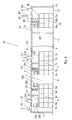
- FIG 2 is a diagrammatic illustration of a preferred embodiment of an inventive travelling dryer 40 that includes the drying chamber I of the figure 1 embodiment, a conditioning chamber 70 and a temporary storage chamber or buffer chamber 60 located between the drying chamber 1 and the conditioning chamber 70.
- the drying chamber 1, the buffer chamber 60 and the conditioning chamber 70 will all preferably have mutually the same width and height and therewith form a continuous passage delimited by walls, such as end walls in respect of the drying chamber 1 and the conditioning chamber 70.
- the three chambers will normally have mutually different lengths.
- a conveyor path moves through said three chambers.
- the conditioning chamber 70 includes a ceiling 72, two side walls, one in front and one behind the sectioned view of figure 2, a third end wall 73 to the left of the figure, said third end wall including a third port through which timber is fed into the conditioning chamber 70, a fourth end wall 74 located at the opposite end of the conditioning chamber 70 and including a fourth port through which conditioned timber is exited from the conditioning chamber 70 into a closed buffer zone, or exited directly from the dryer, and a floor 75 which forms or is means for supporting a conveyor path (not shown).
- This conveyor path is an extension of the conveyor path from the drying chamber 1 and also continues through the buffer chamber 60.
- a timber group 76 consisting, e.g., of three timber stacks 76a-c.
- a third horizontal delimitation 78 Located at a small height above the timber group 76 is a third horizontal delimitation 78. This delimitation has generally the same length as the timber group 76 in the direction of transportation, and extends inwardly of the side walls.
- the conditioning chamber 70 includes means for increasing the humidity of the atmosphere.
- the conditioning chamber 70 also includes a third inlet port 82 for fresh conditioning atmosphere, and a second outlet port 88 for spent conditioning atmosphere.
- a third group of fans or blowers 84 is disposed above the horizontal delimitation 78, between the third inlet port 82 and the heating batteries 80.
- a sensor 86 for measuring the dry temperature of the conditioning atmosphere and a sensor 89 for measuring the wet temperature of said atmosphere. It is also possible, of course, to measure the relative humidity of the atmosphere or some other known parameter that will provide information necessary for controlling conditioning of the timber.
- the buffer chamber 60 is located between the drying chamber 1 and the conditioning chamber 70.
- the ends of the buffer chamber 60 are delimited respectively by the second end wall 4 of the drying chamber and the end wall 73 of the conditioning chamber.
- the buffer chamber is used for the intermediate storage of dried timber stacks prior to passing said stacks into the conditioning chamber 70.
- the conditioning chamber 70 is in direct connection with the drying chamber 1.
- the end wall 73 of the conditioning chamber 1 consists of the end wall 4 of the drying chamber. It is essential that the treatment atmosphere of the conditioning chamber is not influenced by the atmosphere in and the conditions concerning the drying chamber.
Landscapes
- Engineering & Computer Science (AREA)
- Mechanical Engineering (AREA)
- General Engineering & Computer Science (AREA)
- Drying Of Solid Materials (AREA)
Abstract
The present invention relates to a travelling timber dryer (40). The dryer includes a drying chamber (1) that has a first end wall and an opposite second end wall (4), wherein the drying chamber (1) forms a passageway that has at least one zone for drying timber with the aid of a drying atmosphere. The invention is characterized in that the dryer includes a conditioning chamber (70) which is disposed in connection with the drying chamber (1) and delimited therefrom. <IMAGE>
Description
The present invention relates to a travelling timber dryer that includes a drying
chamber which is delimited by a first end wall and an opposite second end wall and
which forms a passageway that has at least one timber drying zone in which timber, or
wood, is dried with the aid of a drying atmosphere, wherein timber stacks consisting of
at least one timber pack on a conveyer path are fed into the drying chamber through a
first port in the first end wall, thereafter moved through the drying chamber and then
exited through a second port in said opposing end wall.
Travelling dryers of this kind are known to the art and used generally at present.
A conditioning zone is sometimes integrated in the drying chamber. This conditioning
zone is not sufficiently effective in equalising the moisture quotient and in reducing mechanical
stresses in the timber, owing to the fact that the control of the air humidity has
technical limitations when this conditioning zone is not delimited to the drying climate
in the remaining part of the chamber. The temperature in the conditioning zone is also
influenced by the temperature in the drying zone.
The present invention relates to a travelling dryer in which timber conditioning is
effected in connection with the timber drying' process and in which the drying atmosphere
and the conditioning atmosphere can be controlled independently of one another.
An object of the invention is to enable the dried timber to be conditioned in direct
connection with the drying process, with or without intermediate storage of the timber in
a buffer zone.
Yet another object of the invention is to provide a travelling dryer in which the
timber on a conveyer path can be readily moved through both drying chamber and conditioning
chamber through the medium of a conveyor path.
The present invention relates to a travelling timber dryer. The dryer includes a
drying chamber that has a first end wall and an opposite second end wall, wherein the
drying chamber forms a passageway that includes at least one zone for drying said timber
with the aid of a drying atmosphere. The invention is characterized by a conditioning
chamber which is delimited from the drying chamber and which is located in connection
therewith. The conditioning chamber will preferably have installed therein steaming
equipment, circulation fans, an air-exchange arrangement and heating batteries. Because
the conditioning zone is delimited, it can be used freely over mutually different conditioning
phase durations without being dependent on the infeed cycle of the travelling
dryer.
Preferred embodiments of the invention will be apparent from the dependent
claims.
Figure 1 is a diagrammatic longitudinally sectioned view of a known travelling
dryer. The illustrated dryer includes a drying chamber 1 in the form of a passageway that
is delimited by a ceiling 2, two side walls situated respectively in front of and behind the
plane of the sectioned view in figure 1, a first end wall 3 to the left of the figure, said
wall including a first port through which timber, or wood is fed into the drying chamber
1, a second end wall 4 at the opposite end of the drying chamber, said second wall including
a second port through which dried timber is exited from the drying chamber 1,
and a floor 5 which forms or is a means for supporting a conveyor path (not shown). The
conveyor path also continues beyond the end walls. The conveyor path functions to
move the timber so as to pass it through the first port, stepwise through the drying
chamber 1, and out through the second port. The timber is usually loaded on transport
carriages in the form of timber stacks of mutually the same height. The first and the second
ports are open solely during the infeed and outfeed of timber respectively.
Two groups of timber 6 and 7 respectively are located in the drying chamber 1.
Each timber group 6, 7 consists of a number of stacks of timber, for instance five stacks
6a-6e and five stacks 7a-7e respectively, as shown in fig. 1. The timber groups 6, 7 may
have mutually different lengths (in the longitudinal directions of the chamber) and thus
do not consist of the same number of stacks. A timber stack consists of at least one timber
pack, often three timber packs, as shown in figure 1. The timber stacks within a timber
group 6, 7 are disposed at a short distance apart, in practice next to one another. The
timber groups 6, 7 are spaced relatively wide apart and also relatively far from the end
walls 3, 4. All timber packs, and therewith all timber stacks, have mutually the same
width, by width being meant the extension of the packs at right angles to the direction in
which the timber moves through the drying chamber 1. The width of the packs is such as
to enable them to move through the drying chamber I with a small clearance to the side
walls.
The drying chamber 1 also includes a respective first and second horizontal delimitation
8 and 9. These delimitations 8, 9 are located at a small distance above respective
timber groups 6, 7 and have essentially the same length as the timber groups in the
transporting direction of the timber and essentially the same width extension between the
side walls.
Between the ceiling 2 of the drying chamber 1 and the first horizontal delimitation
8 above the first timber group 6 are provided first heating batteries 10 for heating of
the timber drying atmosphere. Similarly, second heating batteries 11 are provided above
the second timber group 7, between the ceiling 2 of the drying chamber 1 and the second
horizontal delimitation 9.
The drying chamber I includes in the ceiling 2 two inlet ports 12 and 13 for fresh
drying atmosphere, between the first heating batteries 10 and the first end wall 3 and
between the second heating batteries 11 and the second end wall 4 respectively, these
ports being provided with a butterfly valve. Also provided is an outlet port 20 for spent
drying atmosphere between the first end wall 3 and the first inlet port 12.
A first group of fans or blowers 14 are mounted above the first delimitation 8,
between the first inlet port 12 and the first heating batteries 10. A second group of fans
or blowers 15 are disposed above the second delimitation 9, between the second inlet
port 13 and the second heating batteries 11.
Also provided in the drying chamber 1 are sensors 16a, 16b and 17a, 17b for
measuring the dry temperature of the drying atmosphere above the first delimitation 8
and the second delimitation 9, and also with sensors 18a, 18b and 19a, 19b for measuring
the wet temperature of the drying atmosphere above the first delimitation 8 and the
second delimitation 9 respectively.
Drying atmosphere is introduced through the inlet ports 12 and 13 during the
timber drying process. The drying atmosphere is driven by the fans or blowers 14 and 15
through the respective heating units 10 and 11, so as to form an overpressure in the
space located between the timber groups 6, 7. As a result of this overpressure, the atmosphere
will flow through the timber stacks of the timber groups 6, 7 towards respective
end walls 3 and 4, wherewith drying of the timber takes place. The temperature and
relative humidity of the atmosphere are controlled as a function of the values indicated
by the means for measuring the wet and the dry temperatures. The drying atmosphere
that has flowed through the first timber group 6 leaves the drying chamber 1 through the
outlet port 20. As a result of the placement of the blowers or fans and the forced passage
of the drying atmosphere, the pressure between the timber groups in the central part of
the drying chamber 1 will be higher than the pressure at its ends.
By changing the direction of flow of said atmosphere in the drying chamber, it is
also possible to create in said chamber conditions whereby a higher pressure is obtained
at the ends of said chamber and whereby the lowest chamber pressure is obtained of the
central part of said chamber. This will require changing the feed direction of the fans or
blowers, in other words the flow direction of the atmosphere, the placement of the heating
batteries and the placement of the drying atmosphere ports. The measures necessary
to this end will be obvious to one of average skill in this art.
In a steady state, a carriage loaded with stacks of timber is fed into the drying
chamber through the port provided in the end wall 3 and takes the position referenced
6a. Prior to this, all timber stacks have been moved one step towards the second end wall
4, to the right in the figure, and the timber stack 7E nearest the end wall 4 has been exited
through the port in the second end wall 4. Drying of this timber stack has been completed
and the stack shall now be conditioned for equalising stresses in the timber. All
positions in the drying chamber are fixed.
Figure 2 is a diagrammatic illustration of a preferred embodiment of an inventive
travelling dryer 40 that includes the drying chamber I of the figure 1 embodiment, a
conditioning chamber 70 and a temporary storage chamber or buffer chamber 60 located
between the drying chamber 1 and the conditioning chamber 70. The drying chamber 1,
the buffer chamber 60 and the conditioning chamber 70 will all preferably have mutually
the same width and height and therewith form a continuous passage delimited by walls,
such as end walls in respect of the drying chamber 1 and the conditioning chamber 70.
On the other hand, the three chambers will normally have mutually different lengths. A
conveyor path moves through said three chambers.
The conditioning chamber 70 includes a ceiling 72, two side walls, one in front
and one behind the sectioned view of figure 2, a third end wall 73 to the left of the figure,
said third end wall including a third port through which timber is fed into the conditioning
chamber 70, a fourth end wall 74 located at the opposite end of the conditioning
chamber 70 and including a fourth port through which conditioned timber is exited from
the conditioning chamber 70 into a closed buffer zone, or exited directly from the dryer,
and a floor 75 which forms or is means for supporting a conveyor path (not shown).
This conveyor path is an extension of the conveyor path from the drying chamber 1 and
also continues through the buffer chamber 60.
Shown in the conditioning chamber 70 is a timber group 76 consisting, e.g., of
three timber stacks 76a-c. Located at a small height above the timber group 76 is a third
horizontal delimitation 78. This delimitation has generally the same length as the timber
group 76 in the direction of transportation, and extends inwardly of the side walls.
Provided between the ceiling 72 of the conditioning chamber and the horizontal
delimitation 78 are heating batteries 80, for heating the conditioning atmosphere. Although
not shown, the conditioning chamber includes means for increasing the humidity
of the atmosphere. The conditioning chamber 70 also includes a third inlet port 82 for
fresh conditioning atmosphere, and a second outlet port 88 for spent conditioning atmosphere.
A third group of fans or blowers 84 is disposed above the horizontal delimitation
78, between the third inlet port 82 and the heating batteries 80.
Also provided in the conditioning chamber 80 is a sensor 86 for measuring the
dry temperature of the conditioning atmosphere, and a sensor 89 for measuring the wet
temperature of said atmosphere. It is also possible, of course, to measure the relative
humidity of the atmosphere or some other known parameter that will provide information
necessary for controlling conditioning of the timber.
The buffer chamber 60 is located between the drying chamber 1 and the conditioning
chamber 70. The ends of the buffer chamber 60 are delimited respectively by the
second end wall 4 of the drying chamber and the end wall 73 of the conditioning chamber.
The buffer chamber is used for the intermediate storage of dried timber stacks prior
to passing said stacks into the conditioning chamber 70.
In a further embodiment of the invention, the conditioning chamber 70 is in direct
connection with the drying chamber 1. In this case, the end wall 73 of the conditioning
chamber 1 consists of the end wall 4 of the drying chamber. It is essential that the
treatment atmosphere of the conditioning chamber is not influenced by the atmosphere
in and the conditions concerning the drying chamber.
Claims (11)
- A travelling timber dryer (40) comprising a drying chamber (1) that includes a first end wall (3) and an opposite second end wall (4), wherein the drying chamber (1) forms a passageway that has at least one zone in which timber is dried with the aid of a drying atmosphere, wherein timber stacks (6a - 6e; 7a - 7e) consisting of one or more timber packs located on a conveyor path are fed into the drying chamber (1) through a first port in the first end wall (3), thereafter moved through the drying chamber (1) and exited through a second port in said opposite end wall (4), characterized by a conditioning chamber (70) arranged in connection with the drying chamber (I) and delimited from said drying chamber.
- A travelling dryer according to claim 1, characterized in that the atmosphere in the conditioning chamber (70) is separated from the atmosphere in the drying chamber (1).
- A travelling dryer according to claim 1 or 2, characterized in that the conveyor path continues from the drying chamber up to and through the conditioning chamber (70).
- A travelling dryer according to one or more of claims 1-3, characterized in that the conditioning chamber (70) is constructed together with the drying chamber (1); and in that the second end wall (4) of the drying chamber is common to both the drying chamber (1) and the conditioning chamber (70).
- A travelling dryer according to one or more of claims 1-3, characterized in that the conditioning chamber (70) is separate from the drying chamber (I).
- A travelling dryer according to claim 5, characterized by a buffer chamber (60) disposed between the drying chamber (1) and the conditioning chamber (70).
- A travelling dryer according to claim 5, characterized in that the conditioning chamber (70) has its own ports that delimit the conditioning chamber from the drying chamber atmosphere and the outdoor atmosphere respectively.
- A travelling dryer according to claim 6, characterized in that the conditioning chamber (70) has its own ports that delimit the conditioning chamber from the buffer chamber atmosphere and the outdoor atmosphere respectively.
- A travelling dryer according to one or more of claims 1-6, characterized in that the drying chamber (1) forms two drying zones.
- A travelling dryer according to claim 7, characterized in that the total pressure of the drying atmosphere is highest in the centre part of the drying chamber (1) and lowest at the ends of said chamber (1).
- A travelling dryer according to claim 7, characterized in that the total pressure of the drying atmosphere is lowest at the centre of the drying chamber (1) and highest at the ends of said chamber (1).
Applications Claiming Priority (2)
| Application Number | Priority Date | Filing Date | Title |
|---|---|---|---|
| SE0401545 | 2004-06-16 | ||
| SE0401545A SE0401545L (en) | 2004-06-16 | 2004-06-16 | Walking dryer |
Publications (1)
| Publication Number | Publication Date |
|---|---|
| EP1607703A2 true EP1607703A2 (en) | 2005-12-21 |
Family
ID=32710065
Family Applications (1)
| Application Number | Title | Priority Date | Filing Date |
|---|---|---|---|
| EP04445111A Withdrawn EP1607703A2 (en) | 2004-06-16 | 2004-10-16 | Drying chamber for wood |
Country Status (2)
| Country | Link |
|---|---|
| EP (1) | EP1607703A2 (en) |
| SE (1) | SE0401545L (en) |
Cited By (1)
| Publication number | Priority date | Publication date | Assignee | Title |
|---|---|---|---|---|
| WO2008133583A1 (en) * | 2007-04-26 | 2008-11-06 | Valutec Ab | Method for dynamic control of the drying period in a drying tunnel |
-
2004
- 2004-06-16 SE SE0401545A patent/SE0401545L/en not_active Application Discontinuation
- 2004-10-16 EP EP04445111A patent/EP1607703A2/en not_active Withdrawn
Cited By (1)
| Publication number | Priority date | Publication date | Assignee | Title |
|---|---|---|---|---|
| WO2008133583A1 (en) * | 2007-04-26 | 2008-11-06 | Valutec Ab | Method for dynamic control of the drying period in a drying tunnel |
Also Published As
| Publication number | Publication date |
|---|---|
| SE0401545D0 (en) | 2004-06-16 |
| SE0401545L (en) | 2005-12-17 |
Similar Documents
| Publication | Publication Date | Title |
|---|---|---|
| US5276980A (en) | Reversible conditioned air flow system | |
| EP0122902B1 (en) | Drive-through chamber type timber drying kiln | |
| EP0163711B1 (en) | Drying kiln for drying timber loads | |
| US7571554B2 (en) | Heat recovery and ventilation system for dryers | |
| US11047623B2 (en) | Grain dryer and method for using the same | |
| US5226244A (en) | Circulating air dryer | |
| US3149932A (en) | Drying kiln | |
| US11181319B2 (en) | Sawed wood drying system with secondary air circulation | |
| US20070130787A1 (en) | Veneer dryer | |
| CN100380080C (en) | A device for regulating the temperature of an object | |
| CS203981B2 (en) | Control system for drying plants | |
| EP1607703A2 (en) | Drying chamber for wood | |
| RU2367868C2 (en) | Multilayer-type conveyor drier, particularly for tabular products | |
| EP0162838B1 (en) | Run-through brick drying plant and method for the control of its operation | |
| US6601317B2 (en) | High-efficiency drying kiln particularly for wood-like material | |
| CN116157640A (en) | Dryers for drying plate-like products | |
| US20250297803A1 (en) | Continuous Drying Device | |
| JP2011169508A (en) | Lumber dryer | |
| ES2939250T3 (en) | Nozzle box for a panel-shaped material drying device | |
| US2951294A (en) | Method of drying lumber and a dry kiln for carrying the method into effect | |
| US1420296A (en) | Drying kiln | |
| JP2583214Y2 (en) | Room temperature constant humidity grain dryer | |
| KR200165546Y1 (en) | Drying apparatus of multi-step hotwind circulation for agricultural marine products | |
| SU951039A1 (en) | Continuous action dryer for sawn timbers | |
| FI74137B (en) | FOERFARANDE FOER ATT ARRANGERA CIRKULATION AV TORKLUFTEN I VIRKESTORKAR. |
Legal Events
| Date | Code | Title | Description |
|---|---|---|---|
| PUAI | Public reference made under article 153(3) epc to a published international application that has entered the european phase |
Free format text: ORIGINAL CODE: 0009012 |
|
| AK | Designated contracting states |
Kind code of ref document: A2 Designated state(s): AT BE BG CH CY CZ DE DK EE ES FI FR GB GR HU IE IT LI LU MC NL PL PT RO SE SI SK TR |
|
| AX | Request for extension of the european patent |
Extension state: AL HR LT LV MK |
|
| STAA | Information on the status of an ep patent application or granted ep patent |
Free format text: STATUS: THE APPLICATION IS DEEMED TO BE WITHDRAWN |
|
| 18D | Application deemed to be withdrawn |
Effective date: 20070502 |