EP1607642A1 - Drive shaft - Google Patents
Drive shaft Download PDFInfo
- Publication number
- EP1607642A1 EP1607642A1 EP05010745A EP05010745A EP1607642A1 EP 1607642 A1 EP1607642 A1 EP 1607642A1 EP 05010745 A EP05010745 A EP 05010745A EP 05010745 A EP05010745 A EP 05010745A EP 1607642 A1 EP1607642 A1 EP 1607642A1
- Authority
- EP
- European Patent Office
- Prior art keywords
- boot mounting
- shaft
- mounting part
- extension
- edge
- Prior art date
- Legal status (The legal status is an assumption and is not a legal conclusion. Google has not performed a legal analysis and makes no representation as to the accuracy of the status listed.)
- Granted
Links
- 238000010438 heat treatment Methods 0.000 description 23
- 230000006698 induction Effects 0.000 description 7
- 230000005540 biological transmission Effects 0.000 description 4
- 230000009467 reduction Effects 0.000 description 4
- 229910000851 Alloy steel Inorganic materials 0.000 description 3
- 230000003068 static effect Effects 0.000 description 3
- 239000000463 material Substances 0.000 description 2
- 230000002411 adverse Effects 0.000 description 1
- 230000015572 biosynthetic process Effects 0.000 description 1
- 239000012141 concentrate Substances 0.000 description 1
- 238000010348 incorporation Methods 0.000 description 1
- 239000011347 resin Substances 0.000 description 1
- 229920005989 resin Polymers 0.000 description 1
- 238000007789 sealing Methods 0.000 description 1
- XLYOFNOQVPJJNP-UHFFFAOYSA-N water Substances O XLYOFNOQVPJJNP-UHFFFAOYSA-N 0.000 description 1
Images




Classifications
-
- F—MECHANICAL ENGINEERING; LIGHTING; HEATING; WEAPONS; BLASTING
- F16—ENGINEERING ELEMENTS AND UNITS; GENERAL MEASURES FOR PRODUCING AND MAINTAINING EFFECTIVE FUNCTIONING OF MACHINES OR INSTALLATIONS; THERMAL INSULATION IN GENERAL
- F16C—SHAFTS; FLEXIBLE SHAFTS; ELEMENTS OR CRANKSHAFT MECHANISMS; ROTARY BODIES OTHER THAN GEARING ELEMENTS; BEARINGS
- F16C3/00—Shafts; Axles; Cranks; Eccentrics
- F16C3/02—Shafts; Axles
-
- F—MECHANICAL ENGINEERING; LIGHTING; HEATING; WEAPONS; BLASTING
- F16—ENGINEERING ELEMENTS AND UNITS; GENERAL MEASURES FOR PRODUCING AND MAINTAINING EFFECTIVE FUNCTIONING OF MACHINES OR INSTALLATIONS; THERMAL INSULATION IN GENERAL
- F16D—COUPLINGS FOR TRANSMITTING ROTATION; CLUTCHES; BRAKES
- F16D3/00—Yielding couplings, i.e. with means permitting movement between the connected parts during the drive
- F16D3/84—Shrouds, e.g. casings, covers; Sealing means specially adapted therefor
- F16D3/843—Shrouds, e.g. casings, covers; Sealing means specially adapted therefor enclosed covers
- F16D3/845—Shrouds, e.g. casings, covers; Sealing means specially adapted therefor enclosed covers allowing relative movement of joint parts due to the flexing of the cover
Definitions
- the present invention relates to a drive shaft used in an automotive drive train or the like, and more particularly, relates to a drive shaft comprising a shaft and a constant velocity joint.
- a power transmission device for automobiles or the like normally transmits a driving force through a drive shaft comprising a shaft portion and a constant velocity joint.
- the shaft portion undergoes induction heat treatment or the like to increase its strength, which results in the formation of a hardened layer up to a certain depth from the surface while leaving a non-hardened portion at the shaft core.
- Both ends thereof are in splined engagement with interior members of the constant velocity joint (for an example, refer to Japanese Patent Laid-Open Publication No. 2000-240669, paragraphs 2 to 10 and FIG. 1).
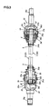
- FIG. 3 shows an example of such a drive train, wherein a shaft portion 1 has boot mounting parts 3, 5 and extensions 4, 6 respectively connected and coaxially formed with both ends of a shaft body 2.
- the inboard-side extension 4 of the shaft portion 1, for example, is connected to a driving-side member of a side gear or the like in a differential, via a tripod-type sliding constant velocity joint 30.
- the outboard-side extension 6, for example, is connected to a driven-side member of a hub or the like in a driven wheel, via a ball-type fixed constant velocity joint 35.
- Boots 33, 38 made from soft rubber, resin or the like are provided in order to seal the interiors of the constant velocity joints 30, 35 against dirt, water and so forth from outside. More specifically, the boots 33, 38 are respectively provided between the constant velocity joints 30, 35 and the boot mounting parts 3, 5 on both ends of the shaft body 2 of the shaft portion 1.
- each of the boots 33, 38 overlay an opening on each of exterior members 31, 36 of the constant velocity joints 30, 35, and is attached using bands 34a, 39a so as to form an airtight seal. Another end is attached via the boot mounting parts 3,5 using bands 34b, 39b so as to form an airtight seal as well.
- boot grooves 3a, 5a are formed on the boot mounting parts 3, 5.
- the inboard-side extension 4 comprises a cylindrical intermediate portion 4a, as well as an end 4b in spline engagement with an interior member 32a of the constant velocity joint 30.
- the intermediate portion 4a has an outer diameter smaller than the boot mounting part 3 and the end 4b. Both ends of the intermediate portion 4a are connected to the boot mounting part 3 and the end 4b by tapered portions 4c, 4d.
- the value for the outer diameter of the intermediate portion 4a of the extension 4 is the minimum necessary for obtaining a required transmitted torque.
- Formed on an opening-side of the inner surface of the exterior member 31 of the constant velocity joint 30 is a flank 31a that faces outward and leaves a slight clearance with the intermediate portion 4a.
- the flank 31a is formed in order to avoid interference with the intermediate portion 4a of the extension 4 at a maximum shaft intersection angle between the extension 4 and the exterior member 31.
- the outboard-side extension 6 comprises a cylindrical intermediate portion 6a, as well as an end 6b in spline engagement with an interior member 37 of the constant velocity joint 35.
- the intermediate portion 6a has a diameter smaller than the boot mounting part 5 and the end 6b. Both ends of the intermediate portion 6a are connected to the boot mounting part 5 and the end 6b by tapered portions 6c, 6d.
- the value for the outer diameter of the intermediate portion 6a of the extension 6 is the minimum necessary in terms of strength.
- Formed on an opening-side of the inner surface of the exterior member 36 of the constant velocity joint 35 is a flank 36a that faces outward, and also leaves a slight clearance with the intermediate portion 6a at a maximum shaft intersection angle.
- the position of a boundary between the intermediate portions 4a, 6a and the base side of tapered portions 4c, 6c at the maximum shaft intersection angle is set somewhat apart from outer edges 31b, 36b of the flanks 31a, 36a of the constant velocity joints 30, 35 and set towards the boot mounting parts 3, 5 sides.
- a hardened layer is formed up to a certain depth from the surface while leaving a non-hardened portion at the shaft core to increase the strength of the shaft in the drive shaft.
- the depth of heat treatment, t/R (where, t: depth of hardened layer, and R: radius of heat treated member), must be set to a certain optimum value.
- alloy steel used in the shaft differs depending on the material, but the optimum heat treatment depth t/R is within the range of 0.55 to 0.8.
- the static torsional strength improves as the heat treatment depth t/R increases; although the fatigue torsional strength falls once the heat treatment depth t/R exceeds a certain limit.
- the heat treatment depth t/R must be set to a value smaller than 0.8.
- the outer diameters of the intermediate portions 4a, 6a of the extensions 4, 6 are set to the minimum values necessary for obtaining the required transmitted torque.
- the boot grooves 3a, 5a are formed on the boot mounting parts 3, 5 to attach the boots 33, 38, and making the outer diameter of the bottom portion of the boot grooves 3a, 5a smaller than the outer diameter of the intermediate portions 4a, 6a would adversely affect strength.
- the outer diameters of the boot mounting parts 3, 5 forming both sides of the boot grooves 3a, 5a are larger than the outer diameters of the intermediate portions 4a, 6a, which results in an outer diameter of the shaft portion 1 that varies among the intermediate portions 4a, 6a and the boot mounting parts 3, 5.
- splines formed on the ends 4b, 6b necessitate an outer diameter larger than that of the intermediate portions 4a, 6a for the sake of ensuring strength, which also means the outer diameter of the shaft portion 1 varies among the intermediate portions 4a, 6a and the ends 4b, 6b as well.
- An induction heat treatment device is used to harden this type of shaft, and adjustment of the heat treatment depth t/R is performed by adjusting the magnitude of high frequency output, coil shape and frequency.
- variations in the outer diameter of the shaft portion 1 among the intermediate portions 4a, 6a and the boot mounting parts 3, 5 also vary the heat capacity per unit length, thus making it difficult to control the heat treatment depth t/R in the surrounding vicinity. This is due to sudden changes in the outer diameter at the tapered portions 4c, 4d, despite performing induction hardening on the shaft aiming for the optimum value. Consequently, the heat treatment depth t/R misses the target value, thereby lowering the strength in this vicinity.
- the drive shaft according to the present invention has a shaft body; a shaft portion provided with a boot mounting part coaxially formed on an end thereof, a coaxially formed extension subsequent to the boot mounting part; and a constant velocity joint attached to an end of the extension via an interior member.
- the extension has an intermediate portion with a cylindrical shape and an outer diameter smaller than that of the boot mounting part and the end of the extension.
- the constant velocity joint has an interior sealed from the outside by an end of a boot that is attached to the boot mounting part so as to form an airtight seal.
- the constant velocity joint is provided on an opening-side of an inner surface of an exterior member thereof with a flank that faces outward and leaves a slight clearance with the intermediate portion at a maximum shaft intersection angle between the extension and the exterior member.
- the intermediate portion has a first edge on the boot mounting part side that is positioned closer to the boot mounting part side than a position corresponding to an outer edge of the flank at the maximum shaft intersection angle or a position in a vicinity thereof.
- the boot mounting part is connected to the first edge by a tapered portion of the shaft body.
- the intermediate portion has a first edge on the boot mounting part side that is positioned closer to the boot mounting part side than a position corresponding to an outer edge of the flank at the maximum shaft intersection angle or a position in a vicinity thereof, and the boot mounting part is connected to the first edge by a tapered portion of the shaft body.
- the tapered portion is set to a maximum length. This in turn moderates variations in the outer diameter of the shaft portion between the intermediate portion and the boot mounting part, whereby variations in the heat capacity per unit length therebetween are moderated as well.
- the intermediate portion prefferably has a second edge on the end side that is positioned closer to the end side than a position corresponding to an inner edge of the flank at the maximum shaft intersection angle or a position in a vicinity thereof. It is also preferable for the end of the extension to be connected to the second edge by a tapered portion on the end side of the shaft body.
- the intermediate portion has a second edge on the end side that is positioned closer to the end side than a position corresponding to an inner edge of the flank at the maximum shaft intersection angle or a position in a vicinity thereof; and the end of the extension is connected to the second edge by a tapered portion on the end side of the shaft body. Therefore, variations in the outer diameter of the drive shaft between the intermediate portion and the end are moderated, whereby variations in the heat capacity per unit length therebetween are moderated as well. Consequently, it is possible to obtain a heat treatment depth t/R at or near an optimum value in the range between the end and the intermediate portion in the extension of the drive shaft. Reductions in local strength resulting from the shape-changing rate of the shaft portion can also be further improved.
- FIGS. 1 and 2 This embodiment applies the present invention to a power transmission device connecting a differential and a drive wheel of an automobile.
- the power transmission device is similar in practice to related art shown in FIG 3, except for the shape of an extension on both ends of the drive shaft.
- a shaft portion 10 in the embodiment comprises a shaft body 11 formed from alloy steel; boot mounting parts 12, 13 coaxially and integrally formed on ends thereof; and extensions 15, 20 coaxially and integrally formed subsequent to the boot mounting parts.
- a tripod-type sliding constant velocity joint 30 is connected to an end 17 of an inboard-side extension (extension) 15, whereas a ball-type fixed constant velocity joint 35 is connected to an end 22 of an outboard-side extension (extension) 20.
- Respective ends of boots 33, 38 also similar to that in the related art shown in FIG 3 overlay an opening in each of exterior members 31, 36 of the constant velocity joints 30, 35, and are attached using bands 34a, 39a so as to form an airtight seal. Other ends are attached to form an airtight seal using bands 34b, 39b via the boot mounting parts 12, 13 on which boot grooves 12a, 13a are formed.
- FIG. 1 is an enlarged view including the inboard-side extension 15 of the shaft portion 10 according to the embodiment.
- An intermediate portion 16 of the inboard-side extension 15 has a cylindrical shape with a fixed diameter. Based upon the same reason explained in the related art, the major diameter is smaller than the outer diameter of the boot mounting part 12 and the end 17.
- An edge 16a (that corresponds to a first edge in the claims) of the intermediate portion 16 is connected to the boot mounting part 12 by a tapered portion 18, whereas an edge 16b (that corresponds to a second edge in the claims) is connected to the end 17 by a tapered portion 19 on the end side.
- the outer diameter of the shaft body 11 is smaller than the outer diameter of the boot mounting part 12, and larger than the diameter of the intermediate portion 16.
- the tripod-type constant velocity joint 30 comprises an exterior member 31, a tripod 32, and three rollers 32c.
- the tripod 32 is formed with three trunnions 32b projecting from an interior member 32a at regular intervals in the circumferential direction.
- the rollers 32c are rotatably supported by each trunnion 32b, in addition to being guided and supported within the guiding grooves 31d of the exterior member 31.
- In spline engagement are the interior member 32a of the constant velocity joint 30 and the end 17 of the inboard-side extension 15.
- the inboard-side extension 15 in which the end 17 is in spline engagement with the interior member 32a is capable of freely swiveling around a center point O1 of the interior member 32a.
- the center point O1 is movable in the center axis direction of the exterior member 31.
- a flank 31a is formed on an opening side of the inner surface on the exterior member 31 of the tripod-type constant velocity joint 30.
- the flank 31a comprises a portion of a conical surface extending outward at a position in the circumferential direction between the guiding grooves 31d.
- the flank 31a is formed such that a slight clearance is created with the intermediate portion 16 of the inboard-side extension 15 at the maximum shaft intersection angle of the exterior member 31 and the inboard-side extension 15, with the center point O1 at the farthest inward position with respect to the exterior member 31.
- edge 16a on the boot mounting part 12 side of the intermediate portion 16 of the inboard-side extension 15 is at a position corresponding to an outer edge 31b of the flank 31a on the exterior member 31 at the maximum shaft intersection angle.
- another edge 16b on the end 17 side of the intermediate portion 16 is positioned closer to the end 17 side than a position corresponding to an inner edge 31c of the flank 31a on the exterior member 31.
- FIG. 2 shows an enlarged view including the outboard-side extension 20 of the shaft portion 10 according to the embodiment.
- an intermediate portion 21 of the outboard-side extension 20 Similar to the inboard-side extension 15, an intermediate portion 21 of the outboard-side extension 20 also has a cylindrical shape. The major diameter thereof is smaller than the outer diameter of the boot mounting part 13 and an end 22. An edge 21a of the intermediate portion 21 is connected to the boot mounting part 13 by a tapered portion 23, whereas another edge 21b is connected to the end 22 by a tapered portion 24 on the end side.
- the intermediate portion 21 has a diameter substantially identical to that of the intermediate portion 16 of the inboard-side extension 15, and which is smaller than that of the shaft body 11.
- the ball.type constant velocity joint 35 comprises an exterior member 36 and an interior member 37, in addition to six balls 37a.
- the exterior member 36 and the interior member 37 are respectively formed at regular intervals in the circumferential direction.
- the balls 37a roll within the ball grooves 36d, 37b.
- In spline engagement are the interior member 37 of the constant velocity joint 35 and the end 22 of the outboard-side extension 20.
- a conical flank 36a extending outward is formed on an opening side of the inner surface on the exterior member 36 of the ball-type constant velocity joint 35.
- the flank 36a is formed such that a slight clearance is created with the intermediate portion 21 of the outboard-side extension 20 at the maximum shaft intersection angle of the exterior member 36 and the outboard-side extension 20.
- the edge 21a on the boot mounting part 13 side of the intermediate portion 21 of the outboard-side extension 20 is in the vicinity of a position corresponding to an outer edge 36b of the flank 36a on the exterior member 36, but positioned closer to the boot mounting part 13 side to a certain extent.
- another edge 21b on the end 22 side of the intermediate portion 21 is in the vicinity of a position corresponding to an inner edge 36c of the flank 36a on the exterior member 36, but positioned closer to the end 22 side to a certain extent.
- the boot mounting parts 12, 13 and the extensions 15, 20 are coaxially formed integral with both ends of the shaft body 11.
- induction heat treatment is performed on the shaft portion 10 with a target value set such that a heat treatment depth t/R reaches an optimum value (0.55 to 0.8, although it may vary for alloy steel depending on the material).
- the edge 16a on the boot mounting part 12 side of the intermediate portion 16 is positioned corresponding to the outer edge 31b of the flank 31a at the maximum shaft intersection angle, with the center point O1 at the farthest position inward with respect to the exterior member 31.
- the length of the tapered portion 18 connecting the edge 16a and the boot mounting part 12 is set to a maximum length.
- This in turn moderates variations in the outer diameter of the shaft portion 10 between the intermediate portion 16 and the boot mounting part 12, whereby variations in the heat capacity per unit length therebetween are moderated as well. Accordingly, fluctuations in the heat treatment depth t/R therebetween are also reduced. Consequently, it is possible to obtain a heat treatment depth t/R at or near the target value in the range between the boot mounting part 12 and the intermediate portion 16 in the extension 15 of the shaft portion 10.
- the possibility of a decrease in local strength is greatly reduced.
- the edge 21a on the boot mounting part 13 side of the intermediate portion 21 is positioned closer to the boot mounting part 13 side than the vicinity of a position corresponding to the outer edge 36b of the flank 36a at the maximum shaft intersection angle.
- the edge 21a and the boot mounting part 13 are connected by the tapered portion 23. Therefore, similar to the inboard-side extension 15, variations in the outer diameter of the shaft portion 10 between the intermediate portion 21 and the boot mounting part 13 are moderated, thereby moderating variations in the heat capacity per unit length therebetween as well. In addition, concentration of the magnetic field during induction hardening is also suppressed.
- Another edge 21b on the end 22 side of the intermediate portion 21 in the outboard-side extension 20 is positioned closer to the end 22 side than the vicinity of a position corresponding to the inner edge 36c of the flank 36a at the maximum shaft intersection angle.
- the other edge 21b and the end 22 are connected by the tapered portion 24 on the end side. Therefore, variations in the outer diameter of the shaft portion 10 between the intermediate portion 21 and the end 22 are moderated, whereby variations in the heat capacity per unit length therebetween are moderated as well. Consequently, controlling the heat treatment depth t/R therebetween becomes easier, making it possible to further improve reductions in local strength compared to related art as shown in FIG 5, similar to the tapered portion 23 and boot mounting part 13 side. Moreover, there is an increase in strength corresponding to the increase in the length of the tapered portion compared to the conventional length, because the intermediate portion with a small diameter is shortened.
- Test 1 Static torsional strength (average) 1.00 1.11 (Using Test 1 as a reference set to 1.0)
- a drive shaft is configured from a shaft body, a shaft portion provided with extensions and boot mounting parts coaxially and integrally formed on ends thereof, and constant velocity joints attached to ends of the extensions via interior members.
- the outer diameter of intermediate portions of the extensions is smaller than that of the ends and the boot mounting parts.
- Formed on the opening-sides of the inner surfaces of the exterior members of the constant velocity joints are flanks that face outward and leave a slight clearance with the intermediate portions.
- Edges forming the boot mounting part sides of the intermediate portions are set to positions corresponding to outer edges of the flanks, and tapered portions connect the edges and the boot mounting parts.
Landscapes
- Engineering & Computer Science (AREA)
- General Engineering & Computer Science (AREA)
- Mechanical Engineering (AREA)
- Ocean & Marine Engineering (AREA)
- Shafts, Cranks, Connecting Bars, And Related Bearings (AREA)
- Sealing Devices (AREA)
Abstract
Description
- The disclosure of Japanese Patent Application No. 2004-176115 filed on June 14, 2004 including the specification, drawings and abstract is incorporated herein by reference in its entirety.
- The present invention relates to a drive shaft used in an automotive drive train or the like, and more particularly, relates to a drive shaft comprising a shaft and a constant velocity joint.
- A power transmission device for automobiles or the like normally transmits a driving force through a drive shaft comprising a shaft portion and a constant velocity joint. The shaft portion undergoes induction heat treatment or the like to increase its strength, which results in the formation of a hardened layer up to a certain depth from the surface while leaving a non-hardened portion at the shaft core. Both ends thereof are in splined engagement with interior members of the constant velocity joint (for an example, refer to Japanese Patent Laid-Open Publication No. 2000-240669,
paragraphs 2 to 10 and FIG. 1). FIG. 3 shows an example of such a drive train, wherein ashaft portion 1 hasboot mounting parts extensions 4, 6 respectively connected and coaxially formed with both ends of ashaft body 2. - The inboard-
side extension 4 of theshaft portion 1, for example, is connected to a driving-side member of a side gear or the like in a differential, via a tripod-type slidingconstant velocity joint 30. Meanwhile, the outboard-side extension 6, for example, is connected to a driven-side member of a hub or the like in a driven wheel, via a ball-type fixedconstant velocity joint 35.Boots constant velocity joints boots constant velocity joints boot mounting parts shaft body 2 of theshaft portion 1. One end of each of theboots exterior members constant velocity joints bands boot mounting parts bands 34b, 39b so as to form an airtight seal as well. In order to fixedly mount theboots boot grooves 3a, 5a are formed on theboot mounting parts - As shown in FIG 4, the inboard-
side extension 4 comprises a cylindricalintermediate portion 4a, as well as an end 4b in spline engagement with aninterior member 32a of theconstant velocity joint 30. Theintermediate portion 4a has an outer diameter smaller than theboot mounting part 3 and the end 4b. Both ends of theintermediate portion 4a are connected to theboot mounting part 3 and the end 4b by tapered portions 4c, 4d. The value for the outer diameter of theintermediate portion 4a of theextension 4 is the minimum necessary for obtaining a required transmitted torque. Formed on an opening-side of the inner surface of theexterior member 31 of theconstant velocity joint 30 is aflank 31a that faces outward and leaves a slight clearance with theintermediate portion 4a. Theflank 31a is formed in order to avoid interference with theintermediate portion 4a of theextension 4 at a maximum shaft intersection angle between theextension 4 and theexterior member 31. - Likewise, as shown in FIG. 5, the outboard-side extension 6 comprises a cylindrical intermediate portion 6a, as well as an end 6b in spline engagement with an
interior member 37 of theconstant velocity joint 35. The intermediate portion 6a has a diameter smaller than theboot mounting part 5 and the end 6b. Both ends of the intermediate portion 6a are connected to theboot mounting part 5 and the end 6b by tapered portions 6c, 6d. Similar to theextension 4, the value for the outer diameter of the intermediate portion 6a of the extension 6 is the minimum necessary in terms of strength. Formed on an opening-side of the inner surface of theexterior member 36 of theconstant velocity joint 35 is aflank 36a that faces outward, and also leaves a slight clearance with the intermediate portion 6a at a maximum shaft intersection angle. - For both the
extension 4 and the extension 6, the position of a boundary between theintermediate portions 4a, 6a and the base side of tapered portions 4c, 6c at the maximum shaft intersection angle is set somewhat apart fromouter edges flanks constant velocity joints boot mounting parts - As mentioned above, a hardened layer is formed up to a certain depth from the surface while leaving a non-hardened portion at the shaft core to increase the strength of the shaft in the drive shaft. In order to obtain a maximum overall increase in strength, the depth of heat treatment, t/R (where, t: depth of hardened layer, and R: radius of heat treated member), must be set to a certain optimum value. For example, alloy steel used in the shaft differs depending on the material, but the optimum heat treatment depth t/R is within the range of 0.55 to 0.8. In other words, the static torsional strength improves as the heat treatment depth t/R increases; although the fatigue torsional strength falls once the heat treatment depth t/R exceeds a certain limit. Therefore, the heat treatment depth t/R must be set to a value smaller than 0.8. The outer diameters of the
intermediate portions 4a, 6a of theextensions 4, 6 are set to the minimum values necessary for obtaining the required transmitted torque. Meanwhile, theboot grooves 3a, 5a are formed on theboot mounting parts boots boot grooves 3a, 5a smaller than the outer diameter of theintermediate portions 4a, 6a would adversely affect strength. Consequently, the outer diameters of theboot mounting parts boot grooves 3a, 5a are larger than the outer diameters of theintermediate portions 4a, 6a, which results in an outer diameter of theshaft portion 1 that varies among theintermediate portions 4a, 6a and theboot mounting parts intermediate portions 4a, 6a for the sake of ensuring strength, which also means the outer diameter of theshaft portion 1 varies among theintermediate portions 4a, 6a and the ends 4b, 6b as well. - An induction heat treatment device is used to harden this type of shaft, and adjustment of the heat treatment depth t/R is performed by adjusting the magnitude of high frequency output, coil shape and frequency. As explained earlier, variations in the outer diameter of the
shaft portion 1 among theintermediate portions 4a, 6a and theboot mounting parts boot mounting parts - In order to achieve the above object, the drive shaft according to the present invention has a shaft body; a shaft portion provided with a boot mounting part coaxially formed on an end thereof, a coaxially formed extension subsequent to the boot mounting part; and a constant velocity joint attached to an end of the extension via an interior member. The extension has an intermediate portion with a cylindrical shape and an outer diameter smaller than that of the boot mounting part and the end of the extension. The constant velocity joint has an interior sealed from the outside by an end of a boot that is attached to the boot mounting part so as to form an airtight seal. The constant velocity joint is provided on an opening-side of an inner surface of an exterior member thereof with a flank that faces outward and leaves a slight clearance with the intermediate portion at a maximum shaft intersection angle between the extension and the exterior member. The intermediate portion has a first edge on the boot mounting part side that is positioned closer to the boot mounting part side than a position corresponding to an outer edge of the flank at the maximum shaft intersection angle or a position in a vicinity thereof. Lastly, the boot mounting part is connected to the first edge by a tapered portion of the shaft body.
- According to a first aspect of the present invention as described above, the intermediate portion has a first edge on the boot mounting part side that is positioned closer to the boot mounting part side than a position corresponding to an outer edge of the flank at the maximum shaft intersection angle or a position in a vicinity thereof, and the boot mounting part is connected to the first edge by a tapered portion of the shaft body. In this state, the tapered portion is set to a maximum length. This in turn moderates variations in the outer diameter of the shaft portion between the intermediate portion and the boot mounting part, whereby variations in the heat capacity per unit length therebetween are moderated as well. Consequently, controlling the heat treatment depth t/R therebetween becomes easier, making it possible to obtain a heat treatment depth t/R at or near an optimum value in the range of the boot mounting part and the intermediate portion in the extension of the drive shaft. Reductions in local strength resulting from the shape-changing rate of the shaft portion can also be greatly improved.
- It is preferable in the drive shaft according to a second aspect of the present invention for the intermediate portion to have a second edge on the end side that is positioned closer to the end side than a position corresponding to an inner edge of the flank at the maximum shaft intersection angle or a position in a vicinity thereof. It is also preferable for the end of the extension to be connected to the second edge by a tapered portion on the end side of the shaft body.
- Furthermore, according to the second aspect of the present invention, the intermediate portion has a second edge on the end side that is positioned closer to the end side than a position corresponding to an inner edge of the flank at the maximum shaft intersection angle or a position in a vicinity thereof; and the end of the extension is connected to the second edge by a tapered portion on the end side of the shaft body. Therefore, variations in the outer diameter of the drive shaft between the intermediate portion and the end are moderated, whereby variations in the heat capacity per unit length therebetween are moderated as well. Consequently, it is possible to obtain a heat treatment depth t/R at or near an optimum value in the range between the end and the intermediate portion in the extension of the drive shaft. Reductions in local strength resulting from the shape-changing rate of the shaft portion can also be further improved.
-
- FIG. 1 is a partial enlarged view illustrating an inboard-side extension and a vicinity thereof in an embodiment of a drive shaft according to the present invention;
- FIG 2 is a partial enlarged view illustrating an outboard-side extension and a vicinity thereof in the embodiment shown in FIG 1;
- FIG. 3 is a vertical cross-sectional view illustrating an example of a power transmission device for an automobile including a drive shaft identical to the present invention;
- FIG 4 is a partial enlarged view identical to FIG 1 that illustrates an example of a drive shaft according to related art; and
- FIG 5 is a partial enlarged view identical to FIG 2 that illustrates an example of a drive shaft according to related art.
-
- Hereinafter, a preferred embodiment of a drive shaft according to the present invention will be described based upon an embodiment shown in FIGS. 1 and 2. This embodiment applies the present invention to a power transmission device connecting a differential and a drive wheel of an automobile. The power transmission device is similar in practice to related art shown in FIG 3, except for the shape of an extension on both ends of the drive shaft.
- A
shaft portion 10 in the embodiment comprises ashaft body 11 formed from alloy steel;boot mounting parts extensions end 17 of an inboard-side extension (extension) 15, whereas a ball-type fixed constant velocity joint 35 is connected to anend 22 of an outboard-side extension (extension) 20. Respective ends ofboots exterior members bands seal using bands 34b, 39b via theboot mounting parts boot grooves - FIG. 1 is an enlarged view including the inboard-
side extension 15 of theshaft portion 10 according to the embodiment. Anintermediate portion 16 of the inboard-side extension 15 has a cylindrical shape with a fixed diameter. Based upon the same reason explained in the related art, the major diameter is smaller than the outer diameter of theboot mounting part 12 and theend 17. An edge 16a (that corresponds to a first edge in the claims) of theintermediate portion 16 is connected to theboot mounting part 12 by a taperedportion 18, whereas an edge 16b (that corresponds to a second edge in the claims) is connected to theend 17 by a taperedportion 19 on the end side. The outer diameter of theshaft body 11 is smaller than the outer diameter of theboot mounting part 12, and larger than the diameter of theintermediate portion 16. - As mainly shown in FIG 3, the tripod-type constant velocity joint 30 comprises an
exterior member 31, atripod 32, and threerollers 32c. On an inner surface of theexterior member 31, threeaxial guiding grooves 31d are formed at regular intervals in the circumferential direction. Thetripod 32 is formed with threetrunnions 32b projecting from aninterior member 32a at regular intervals in the circumferential direction. Therollers 32c are rotatably supported by eachtrunnion 32b, in addition to being guided and supported within the guidinggrooves 31d of theexterior member 31. In spline engagement are theinterior member 32a of the constant velocity joint 30 and theend 17 of the inboard-side extension 15. Also in coaxial spline engagement are ashaft 31e coaxially projecting from theexterior member 31 in the axis direction and a side gear (not shown) of a differential. The inboard-side extension 15 in which theend 17 is in spline engagement with theinterior member 32a is capable of freely swiveling around a center point O1 of theinterior member 32a. Moreover, the center point O1 is movable in the center axis direction of theexterior member 31. - As shown in FIGS. 1 and 3, a
flank 31a is formed on an opening side of the inner surface on theexterior member 31 of the tripod-type constant velocity joint 30. Theflank 31a comprises a portion of a conical surface extending outward at a position in the circumferential direction between the guidinggrooves 31d. As shown in FIG. 1, theflank 31a is formed such that a slight clearance is created with theintermediate portion 16 of the inboard-side extension 15 at the maximum shaft intersection angle of theexterior member 31 and the inboard-side extension 15, with the center point O1 at the farthest inward position with respect to theexterior member 31. In addition, the edge 16a on theboot mounting part 12 side of theintermediate portion 16 of the inboard-side extension 15 is at a position corresponding to anouter edge 31b of theflank 31a on theexterior member 31 at the maximum shaft intersection angle. Meanwhile, another edge 16b on theend 17 side of theintermediate portion 16 is positioned closer to theend 17 side than a position corresponding to an inner edge 31c of theflank 31a on theexterior member 31. - FIG. 2 shows an enlarged view including the outboard-
side extension 20 of theshaft portion 10 according to the embodiment. Similar to the inboard-side extension 15, anintermediate portion 21 of the outboard-side extension 20 also has a cylindrical shape. The major diameter thereof is smaller than the outer diameter of theboot mounting part 13 and anend 22. Anedge 21a of theintermediate portion 21 is connected to theboot mounting part 13 by a taperedportion 23, whereas another edge 21b is connected to theend 22 by a taperedportion 24 on the end side. Theintermediate portion 21 has a diameter substantially identical to that of theintermediate portion 16 of the inboard-side extension 15, and which is smaller than that of theshaft body 11. - As mainly shown in FIG 3, the ball.type constant velocity joint 35 comprises an
exterior member 36 and aninterior member 37, in addition to sixballs 37a. On theexterior member 36 and theinterior member 37, sixball grooves balls 37a roll within theball grooves interior member 37 of the constant velocity joint 35 and theend 22 of the outboard-side extension 20. Also in spline engagement are ashaft 36e coaxially projecting from theexterior member 36 in the axis direction and a hub of a drive wheeL The outboard-side extension 20 in which theend 22 is in spline engagement with theinterior member 37 is capable of freely swiveling around acenter point 02 of theinterior member 37. - As shown in FIGS. 2 and 3, a
conical flank 36a extending outward is formed on an opening side of the inner surface on theexterior member 36 of the ball-type constant velocity joint 35. As shown in FIG. 2, theflank 36a is formed such that a slight clearance is created with theintermediate portion 21 of the outboard-side extension 20 at the maximum shaft intersection angle of theexterior member 36 and the outboard-side extension 20. In addition, at the maximum shaft intersection angle, theedge 21a on theboot mounting part 13 side of theintermediate portion 21 of the outboard-side extension 20 is in the vicinity of a position corresponding to anouter edge 36b of theflank 36a on theexterior member 36, but positioned closer to theboot mounting part 13 side to a certain extent. Meanwhile, another edge 21b on theend 22 side of theintermediate portion 21 is in the vicinity of a position corresponding to aninner edge 36c of theflank 36a on theexterior member 36, but positioned closer to theend 22 side to a certain extent. - In the
shaft portion 10, theboot mounting parts extensions shaft body 11. To obtain a maximum overall increase in strength, induction heat treatment is performed on theshaft portion 10 with a target value set such that a heat treatment depth t/R reaches an optimum value (0.55 to 0.8, although it may vary for alloy steel depending on the material). In the inboard-side extension 15, the edge 16a on theboot mounting part 12 side of theintermediate portion 16 is positioned corresponding to theouter edge 31b of theflank 31a at the maximum shaft intersection angle, with the center point O1 at the farthest position inward with respect to theexterior member 31. In this state, the length of the taperedportion 18 connecting the edge 16a and theboot mounting part 12 is set to a maximum length. This in turn moderates variations in the outer diameter of theshaft portion 10 between theintermediate portion 16 and theboot mounting part 12, whereby variations in the heat capacity per unit length therebetween are moderated as well. Accordingly, fluctuations in the heat treatment depth t/R therebetween are also reduced. Consequently, it is possible to obtain a heat treatment depth t/R at or near the target value in the range between theboot mounting part 12 and theintermediate portion 16 in theextension 15 of theshaft portion 10. Compared to related art such as that shown in FIG. 4, the possibility of a decrease in local strength is greatly reduced. Moreover, there is an increase in strength corresponding to the increase in the length of the tapered portion compared to a conventional length, because the intermediate portion with its small diameter is shortened. - In the outboard-
side extension 20 as well, theedge 21a on theboot mounting part 13 side of theintermediate portion 21 is positioned closer to theboot mounting part 13 side than the vicinity of a position corresponding to theouter edge 36b of theflank 36a at the maximum shaft intersection angle. Theedge 21a and theboot mounting part 13 are connected by the taperedportion 23. Therefore, similar to the inboard-side extension 15, variations in the outer diameter of theshaft portion 10 between theintermediate portion 21 and theboot mounting part 13 are moderated, thereby moderating variations in the heat capacity per unit length therebetween as well. In addition, concentration of the magnetic field during induction hardening is also suppressed. Consequently, controlling the heat treatment depth t/R therebetween becomes easier, making it possible to obtain a heat treatment depth t/R at or near the target value in the range of theboot mounting parts intermediate portions extensions shaft portion 10. Reductions in local strength can also be greatly improved compared to related art as shown in FIG 5. - Another edge 21b on the
end 22 side of theintermediate portion 21 in the outboard-side extension 20 is positioned closer to theend 22 side than the vicinity of a position corresponding to theinner edge 36c of theflank 36a at the maximum shaft intersection angle. The other edge 21b and theend 22 are connected by the taperedportion 24 on the end side. Therefore, variations in the outer diameter of theshaft portion 10 between theintermediate portion 21 and theend 22 are moderated, whereby variations in the heat capacity per unit length therebetween are moderated as well. Consequently, controlling the heat treatment depth t/R therebetween becomes easier, making it possible to further improve reductions in local strength compared to related art as shown in FIG 5, similar to the taperedportion 23 andboot mounting part 13 side. Moreover, there is an increase in strength corresponding to the increase in the length of the tapered portion compared to the conventional length, because the intermediate portion with a small diameter is shortened. - Shown below are the results for static torsional strength after induction heat treatment for a drive shaft with the shape of related art shown in FIGS. 4 and 5 (Test 1), and a drive shaft with the shape of the present invention shown in FIGS. 1 and 2 (Test 2). The values shown
use Test 1 as a reference (1.0).Test 1Test 2Static torsional strength (average) 1.00 1.11 (Using Test 1 as a reference set to 1.0) - A drive shaft is configured from a shaft body, a shaft portion provided with extensions and boot mounting parts coaxially and integrally formed on ends thereof, and constant velocity joints attached to ends of the extensions via interior members. The outer diameter of intermediate portions of the extensions is smaller than that of the ends and the boot mounting parts. Formed on the opening-sides of the inner surfaces of the exterior members of the constant velocity joints are flanks that face outward and leave a slight clearance with the intermediate portions. Edges forming the boot mounting part sides of the intermediate portions are set to positions corresponding to outer edges of the flanks, and tapered portions connect the edges and the boot mounting parts.
Claims (2)
- A drive shaft comprising:a shaft body;a shaft portion provided with a boot mounting part coaxially formed on an end thereof, a coaxially formed extension subsequent to the boot mounting part; anda constant velocity joint attached to an end of the extension via an interior member, whereinthe extension has an intermediate portion with a cylindrical shape and an outer diameter smaller than that of the boot mounting part and the end of the extension,the constant velocity joint has an interior sealed from the outside by an end of a boot that is attached to the boot mounting part so as to form an airtight seal,the constant velocity joint is provided on an opening-side of an inner surface of an exterior member thereof with a flank that faces outward and leaves a slight clearance with the intermediate portion at a maximum shaft intersection angle between the extension and the exterior member,the intermediate portion has a first edge on the boot mounting part side that is positioned closer to the boot mounting part side than a position corresponding to an outer edge of the flank at the maximum shaft intersection angle or a position in a vicinity thereof, andthe boot mounting part is connected to the first edge by a tapered portion of the shaft body.
- The drive shaft according to claim 1, wherein
the intermediate portion has a second edge on the end side that is positioned closer to the end side than a position corresponding to an inner edge of the flank at the maximum shaft intersection angle or a position in a vicinity thereof; and
the end of the extension is connected to the second edge by a tapered portion on the end side of the shaft body.
Applications Claiming Priority (2)
| Application Number | Priority Date | Filing Date | Title |
|---|---|---|---|
| JP2004176115 | 2004-06-14 | ||
| JP2004176115A JP4725039B2 (en) | 2004-06-14 | 2004-06-14 | Drive shaft |
Publications (2)
| Publication Number | Publication Date |
|---|---|
| EP1607642A1 true EP1607642A1 (en) | 2005-12-21 |
| EP1607642B1 EP1607642B1 (en) | 2012-12-26 |
Family
ID=34936635
Family Applications (1)
| Application Number | Title | Priority Date | Filing Date |
|---|---|---|---|
| EP05010745A Ceased EP1607642B1 (en) | 2004-06-14 | 2005-05-18 | Drive shaft |
Country Status (3)
| Country | Link |
|---|---|
| US (1) | US7435182B2 (en) |
| EP (1) | EP1607642B1 (en) |
| JP (1) | JP4725039B2 (en) |
Families Citing this family (7)
| Publication number | Priority date | Publication date | Assignee | Title |
|---|---|---|---|---|
| US7793953B2 (en) * | 2006-08-15 | 2010-09-14 | Ride The Ducks International, Llc | Steering knuckle boot |
| WO2015153431A2 (en) | 2014-04-04 | 2015-10-08 | Dana Automotive Systems Group, Llc | Constant velocity joint assembly |
| WO2017139581A1 (en) | 2016-02-10 | 2017-08-17 | Dana Automotive Systems Group, Llc | Direct pinion mount constant velocity joint |
| KR20180133904A (en) | 2016-05-10 | 2018-12-17 | 데이나 오토모티브 시스템즈 그룹 엘엘씨 | Boot assembly for constant velocity joint |
| EP3601826A1 (en) | 2017-03-31 | 2020-02-05 | Dana Automotive Systems Group, LLC | A constant velocity joint assembly |
| US12247621B2 (en) * | 2017-10-24 | 2025-03-11 | Ntn Corporation | Wheel bearing device |
| USD987697S1 (en) * | 2021-05-14 | 2023-05-30 | Zhejiang Precise Driveline Machinery Co., Ltd | Protective cover for drive shaft |
Citations (5)
| Publication number | Priority date | Publication date | Assignee | Title |
|---|---|---|---|---|
| US4904227A (en) * | 1987-04-30 | 1990-02-27 | Honda Giken Kogyo Kabushiki Kaisha | Stopper apparatus for inner member in sliding universal joints |
| US5632683A (en) * | 1992-09-30 | 1997-05-27 | Ntn Corporation | Homokinetic joint having ball retaining structure |
| JP2000240669A (en) | 1999-02-18 | 2000-09-05 | Ntn Corp | Power transmission shaft |
| US6319337B1 (en) * | 1999-02-10 | 2001-11-20 | Ntn Corporation | Power transmission shaft |
| US6390928B1 (en) * | 1999-08-16 | 2002-05-21 | Gkn Lobro Gmbh | Driveshaft adapted to a preferred torque transmitting direction |
Family Cites Families (8)
| Publication number | Priority date | Publication date | Assignee | Title |
|---|---|---|---|---|
| JPS594823A (en) * | 1982-06-29 | 1984-01-11 | Hitachi Ltd | Gas turbine combustor for low calory gas |
| JPS60129519A (en) * | 1983-12-14 | 1985-07-10 | Hitachi Zosen Corp | Dust removing method for exhaust gas |
| JPH01303319A (en) * | 1988-05-30 | 1989-12-07 | Toyoda Mach Works Ltd | Uniform joint |
| NL8801394A (en) * | 1988-05-31 | 1989-12-18 | Skf Ind Trading & Dev | HOMOKINETIC COUPLING. |
| JPH11101256A (en) * | 1997-09-29 | 1999-04-13 | Ntn Corp | Constant velocity joint |
| JP2000065083A (en) * | 1998-08-24 | 2000-03-03 | Nippon Seiko Kk | Constant velocity joint |
| JP2001323945A (en) * | 2000-05-15 | 2001-11-22 | Ntn Corp | Constant velocity joint |
| JP4219583B2 (en) * | 2001-10-26 | 2009-02-04 | Ntn株式会社 | Fixed type constant velocity universal joint |
-
2004
- 2004-06-14 JP JP2004176115A patent/JP4725039B2/en not_active Expired - Lifetime
-
2005
- 2005-05-18 EP EP05010745A patent/EP1607642B1/en not_active Ceased
- 2005-05-26 US US11/137,578 patent/US7435182B2/en not_active Expired - Fee Related
Patent Citations (5)
| Publication number | Priority date | Publication date | Assignee | Title |
|---|---|---|---|---|
| US4904227A (en) * | 1987-04-30 | 1990-02-27 | Honda Giken Kogyo Kabushiki Kaisha | Stopper apparatus for inner member in sliding universal joints |
| US5632683A (en) * | 1992-09-30 | 1997-05-27 | Ntn Corporation | Homokinetic joint having ball retaining structure |
| US6319337B1 (en) * | 1999-02-10 | 2001-11-20 | Ntn Corporation | Power transmission shaft |
| JP2000240669A (en) | 1999-02-18 | 2000-09-05 | Ntn Corp | Power transmission shaft |
| US6390928B1 (en) * | 1999-08-16 | 2002-05-21 | Gkn Lobro Gmbh | Driveshaft adapted to a preferred torque transmitting direction |
Also Published As
| Publication number | Publication date |
|---|---|
| US7435182B2 (en) | 2008-10-14 |
| JP2005351465A (en) | 2005-12-22 |
| EP1607642B1 (en) | 2012-12-26 |
| JP4725039B2 (en) | 2011-07-13 |
| US20050277479A1 (en) | 2005-12-15 |
Similar Documents
| Publication | Publication Date | Title |
|---|---|---|
| US4950206A (en) | Constant velocity ratio universal joints | |
| US8047724B2 (en) | Bearing device for wheel | |
| GB2339465A (en) | Drive assembly | |
| EP1607642B1 (en) | Drive shaft | |
| US10962063B2 (en) | Fixed constant velocity universal joint | |
| US20200217371A1 (en) | Power transmission shaft | |
| US7217194B2 (en) | Constant velocity universal joint | |
| US9133887B2 (en) | Constant velocity joint | |
| US20160356317A1 (en) | Constant-velocity joint | |
| WO2023026831A1 (en) | Sliding-type constant-velocity joint | |
| JP2006090518A (en) | Power transmission device | |
| JP4279301B2 (en) | Drive wheel bearing device | |
| EP3159564B1 (en) | Manufacturing method for constant velocity universal joint outer joint member and outer joint member | |
| EP1450059B1 (en) | Fixed type constant velocity joint | |
| CN103748375A (en) | Constant velocity universal joint and method for producing same | |
| CN120720340A (en) | Outer coupling member for constant velocity universal joint and fixed constant velocity universal joint equipped with the same | |
| JP2006064060A (en) | Constant velocity universal joint | |
| KR20170094861A (en) | Cross Groove Constant Velocity Joint | |
| US20030224860A1 (en) | Constant velocity joints | |
| WO2025205018A1 (en) | Outer joint member for constant velocity universal joint | |
| JP5128396B2 (en) | Inner joint member of constant velocity universal joint, assembly method of constant velocity universal joint, drive shaft assembly, and propeller shaft assembly | |
| JPH11280779A (en) | Universal joint | |
| WO2025047345A1 (en) | Sliding constant velocity universal joint and wheel driving device provided with same | |
| JP2009191901A (en) | Cage of constant speed universal joint, propeller shaft assembly, and drive shaft assembly | |
| CN118257792A (en) | Power transmission shaft, drive shaft, and outer coupling member |
Legal Events
| Date | Code | Title | Description |
|---|---|---|---|
| PUAI | Public reference made under article 153(3) epc to a published international application that has entered the european phase |
Free format text: ORIGINAL CODE: 0009012 |
|
| AK | Designated contracting states |
Kind code of ref document: A1 Designated state(s): AT BE BG CH CY CZ DE DK EE ES FI FR GB GR HU IE IS IT LI LT LU MC NL PL PT RO SE SI SK TR |
|
| AX | Request for extension of the european patent |
Extension state: AL BA HR LV MK YU |
|
| 17P | Request for examination filed |
Effective date: 20060619 |
|
| AKX | Designation fees paid |
Designated state(s): DE |
|
| RAP1 | Party data changed (applicant data changed or rights of an application transferred) |
Owner name: JTEKT CORPORATION |
|
| 17Q | First examination report despatched |
Effective date: 20061027 |
|
| RIN1 | Information on inventor provided before grant (corrected) |
Inventor name: NISHI, KOJIJTEKT CORPORATION Inventor name: ICHIKAWA, KAZUYUKIJTEKT CORPORATION Inventor name: INAGAKI, YUJIJTEKT CORPORATION |
|
| GRAP | Despatch of communication of intention to grant a patent |
Free format text: ORIGINAL CODE: EPIDOSNIGR1 |
|
| GRAS | Grant fee paid |
Free format text: ORIGINAL CODE: EPIDOSNIGR3 |
|
| GRAA | (expected) grant |
Free format text: ORIGINAL CODE: 0009210 |
|
| AK | Designated contracting states |
Kind code of ref document: B1 Designated state(s): DE |
|
| REG | Reference to a national code |
Ref country code: DE Ref legal event code: R096 Ref document number: 602005037558 Country of ref document: DE Effective date: 20130307 |
|
| PLBE | No opposition filed within time limit |
Free format text: ORIGINAL CODE: 0009261 |
|
| STAA | Information on the status of an ep patent application or granted ep patent |
Free format text: STATUS: NO OPPOSITION FILED WITHIN TIME LIMIT |
|
| 26N | No opposition filed |
Effective date: 20130927 |
|
| REG | Reference to a national code |
Ref country code: DE Ref legal event code: R097 Ref document number: 602005037558 Country of ref document: DE Effective date: 20130927 |
|
| PGFP | Annual fee paid to national office [announced via postgrant information from national office to epo] |
Ref country code: DE Payment date: 20190508 Year of fee payment: 15 |
|
| REG | Reference to a national code |
Ref country code: DE Ref legal event code: R119 Ref document number: 602005037558 Country of ref document: DE |
|
| PG25 | Lapsed in a contracting state [announced via postgrant information from national office to epo] |
Ref country code: DE Free format text: LAPSE BECAUSE OF NON-PAYMENT OF DUE FEES Effective date: 20201201 |