EP1607250A1 - Self cooling actuator - Google Patents
Self cooling actuator Download PDFInfo
- Publication number
- EP1607250A1 EP1607250A1 EP05104711A EP05104711A EP1607250A1 EP 1607250 A1 EP1607250 A1 EP 1607250A1 EP 05104711 A EP05104711 A EP 05104711A EP 05104711 A EP05104711 A EP 05104711A EP 1607250 A1 EP1607250 A1 EP 1607250A1
- Authority
- EP
- European Patent Office
- Prior art keywords
- actuator
- aperture
- housing
- armature
- air
- Prior art date
- Legal status (The legal status is an assumption and is not a legal conclusion. Google has not performed a legal analysis and makes no representation as to the accuracy of the status listed.)
- Granted
Links
- 238000001816 cooling Methods 0.000 title claims description 3
- 239000000725 suspension Substances 0.000 claims abstract description 12
- 230000003247 decreasing effect Effects 0.000 claims description 10
- 238000000034 method Methods 0.000 claims description 10
- 238000007789 sealing Methods 0.000 claims description 5
- 239000012530 fluid Substances 0.000 claims 1
- 239000007788 liquid Substances 0.000 claims 1
- XLYOFNOQVPJJNP-UHFFFAOYSA-N water Substances O XLYOFNOQVPJJNP-UHFFFAOYSA-N 0.000 description 4
- 230000001681 protective effect Effects 0.000 description 2
- CWYNVVGOOAEACU-UHFFFAOYSA-N Fe2+ Chemical compound [Fe+2] CWYNVVGOOAEACU-UHFFFAOYSA-N 0.000 description 1
- 229910000831 Steel Inorganic materials 0.000 description 1
- 230000003044 adaptive effect Effects 0.000 description 1
- 239000000428 dust Substances 0.000 description 1
- 230000005484 gravity Effects 0.000 description 1
- 239000000463 material Substances 0.000 description 1
- 238000012986 modification Methods 0.000 description 1
- 230000004048 modification Effects 0.000 description 1
- 210000003254 palate Anatomy 0.000 description 1
- 230000002028 premature Effects 0.000 description 1
- 238000000926 separation method Methods 0.000 description 1
- 239000010959 steel Substances 0.000 description 1
Images

Classifications
-
- B—PERFORMING OPERATIONS; TRANSPORTING
- B60—VEHICLES IN GENERAL
- B60G—VEHICLE SUSPENSION ARRANGEMENTS
- B60G17/00—Resilient suspensions having means for adjusting the spring or vibration-damper characteristics, for regulating the distance between a supporting surface and a sprung part of vehicle or for locking suspension during use to meet varying vehicular or surface conditions, e.g. due to speed or load
- B60G17/015—Resilient suspensions having means for adjusting the spring or vibration-damper characteristics, for regulating the distance between a supporting surface and a sprung part of vehicle or for locking suspension during use to meet varying vehicular or surface conditions, e.g. due to speed or load the regulating means comprising electric or electronic elements
- B60G17/0152—Resilient suspensions having means for adjusting the spring or vibration-damper characteristics, for regulating the distance between a supporting surface and a sprung part of vehicle or for locking suspension during use to meet varying vehicular or surface conditions, e.g. due to speed or load the regulating means comprising electric or electronic elements characterised by the action on a particular type of suspension unit
- B60G17/0157—Resilient suspensions having means for adjusting the spring or vibration-damper characteristics, for regulating the distance between a supporting surface and a sprung part of vehicle or for locking suspension during use to meet varying vehicular or surface conditions, e.g. due to speed or load the regulating means comprising electric or electronic elements characterised by the action on a particular type of suspension unit non-fluid unit, e.g. electric motor
-
- H—ELECTRICITY
- H02—GENERATION; CONVERSION OR DISTRIBUTION OF ELECTRIC POWER
- H02K—DYNAMO-ELECTRIC MACHINES
- H02K11/00—Structural association of dynamo-electric machines with electric components or with devices for shielding, monitoring or protection
- H02K11/30—Structural association with control circuits or drive circuits
- H02K11/33—Drive circuits, e.g. power electronics
-
- H—ELECTRICITY
- H02—GENERATION; CONVERSION OR DISTRIBUTION OF ELECTRIC POWER
- H02K—DYNAMO-ELECTRIC MACHINES
- H02K33/00—Motors with reciprocating, oscillating or vibrating magnet, armature or coil system
- H02K33/16—Motors with reciprocating, oscillating or vibrating magnet, armature or coil system with polarised armatures moving in alternate directions by reversal or energisation of a single coil system
-
- H—ELECTRICITY
- H02—GENERATION; CONVERSION OR DISTRIBUTION OF ELECTRIC POWER
- H02K—DYNAMO-ELECTRIC MACHINES
- H02K9/00—Arrangements for cooling or ventilating
- H02K9/02—Arrangements for cooling or ventilating by ambient air flowing through the machine
-
- B—PERFORMING OPERATIONS; TRANSPORTING
- B60—VEHICLES IN GENERAL
- B60G—VEHICLE SUSPENSION ARRANGEMENTS
- B60G2202/00—Indexing codes relating to the type of spring, damper or actuator
- B60G2202/40—Type of actuator
- B60G2202/42—Electric actuator
-
- B—PERFORMING OPERATIONS; TRANSPORTING
- B60—VEHICLES IN GENERAL
- B60G—VEHICLE SUSPENSION ARRANGEMENTS
- B60G2202/00—Indexing codes relating to the type of spring, damper or actuator
- B60G2202/40—Type of actuator
- B60G2202/42—Electric actuator
- B60G2202/422—Linear motor
-
- B—PERFORMING OPERATIONS; TRANSPORTING
- B60—VEHICLES IN GENERAL
- B60G—VEHICLE SUSPENSION ARRANGEMENTS
- B60G2400/00—Indexing codes relating to detected, measured or calculated conditions or factors
- B60G2400/70—Temperature of vehicle part or in the vehicle
- B60G2400/71—Temperature of vehicle part or in the vehicle of suspension unit
-
- H—ELECTRICITY
- H02—GENERATION; CONVERSION OR DISTRIBUTION OF ELECTRIC POWER
- H02K—DYNAMO-ELECTRIC MACHINES
- H02K2205/00—Specific aspects not provided for in the other groups of this subclass relating to casings, enclosures, supports
- H02K2205/09—Machines characterised by drain passages or by venting, breathing or pressure compensating means
Definitions
- the description relates to active suspension systems.
- One type of actuator is an electromagnetic actuator in which current through a coil generates a magnetic field that causes movement of an armature coupled to the wheels. This coil current is provided by power electronic circuits. The currents in both the coil and the circuits generate heat.
- the components of the actuator including the power electronic circuits, are enclosed in a protective housing. Because the power electronics are confined in a small enclosed space, the need to dissipate heat becomes more significant.
- An aspect of the invention is an actuator for an active suspension system.
- the actuator includes an armature and a housing enclosing the armature.
- the housing has an interior volume that varies in response to movement of the armature. In response to movement of the armature, air passes through a first aperture defined by the housing.
- the housing also defines a second aperture through which air moves in response to movement of the armature.
- air In response to movement of the armature, air is either drawn into the interior through the first and second apertures or expelled from the interior through the first and second apertures. Alternatively, in response to movements of the armature, air is drawn into the housing through the first aperture and expelled through the second aperture.
- electronic circuitry for effecting moveme nt of the armature is disposed within the interior of the housing.
- FIG. 1 Other embodiments include those in which the housing defines a labyrinth extending between the first and second apertures. An optional filter is placed in the labyrinth thus formed.
- Optional first and second one-way valves can be disposed to allow admission of air into the housing interior through the first aperture and expulsion of air from the housing interior through the second aperture.
- the second one-way valve can also be disposed to allow expulsion of water from the housing interior through the second aperture.
- the housing includes a first portion coupled to the armature; and a second portion coupled to the first portion.
- the first portion can include a flexible portion joined to the second portion.
- the first portion can, for example, include bellows.
- Other embodiments include those in which the first portion of the housing includes a moveable portion, and those in which the second portion is a rigid portion.
- the first portion can include a first cylinder and the second portion can include a second cylinder.
- the first and second cylinder have different radii so that one of the first and second cylinders can slide into the other in response to movement of the armature.
- the first portion can include a piston head and the second portion can include a cylinder sized to accommodate the piston head. The piston head and the cylinder together define a volume that changes in response to movement of the armature.
- the first portion defines a second aperture through which air moves in response to movement of the armature.
- the second portion defines both a second aperture through which air moves in response to movement of the armature and a first aperture.
- the second portion can optionally define a labyrinth between the first and second apertures.
- inventions include those in which a first one-way valve is disposed to allow admission of air into the housing interior through the first aperture.
- a second one-way valve can then be disposed to allow expulsion of air from the housing interior through the second aperture.
- the invention includes a method for cooling components of an actuator in an active suspension system by enclosing the components in a housing having an interior volume. The interior volume is then increased. This draws air into the interior volume and passes it over the components of the actuator. Then, the interior volume is decreased to expel air from the housing.
- increasing the interior volume includes causing air to be drawn into the housing through a first aperture. Decreasing the interior volume includes causing air to be expelled from the housing through the first aperture.
- increasing the interior volume includes causing air to be drawn into the housing through a first aperture. Decreasing the interior volume includes causing air to be expelled from the housing through a second aperture.
- One way to cause air to be drawn into the aperture is to cause a first one -way valve sealing the first aperture to open.
- the expulsion of air from the housing can then include causing the opening of a second one-way valve that seals the second aperture.
- changing the interior volume can include passing current through a coil in the housing.
- the actuator in this case has a moveable armature coupled to a flexible portion of the housing.
- An adaptive suspension system for a motor vehicle includes four electromagnetic actuators 10 mounted in each of the four corners of the motor vehicle. In response to signals from a controller, the actuators 10 apply forces to dynamically control the separation between a vehicle chassis and the road surface. These forces collectively control the attitude of the chassis relative to the road surface.
- An exemplary actuator 10 which is shown in FIG. 1, converts electrical energy into mechanical energy in response to a signal provided by a controller (not shown).
- This signal is received by components mounted on circuit boards 12 con tained within the actuator 10.
- components on the circuit boards 12 cooperate to generate a current through coils 14 that are disposed to magnetically couple to a magnetic armature 16.
- the coils 14 may be further surrounded by ferrous materials such as steel. This current causes the armature 16 to move along a longitudinal axis of the coils 14.
- the controller may be inside or outside the enclosure.
- a suitable actuator 10 is that disclosed in U.S. Patent 4,981,309, the contents of which are incorporated herein by reference.
- the illustrated actuator 10 is intended to operate in an environment laden with dust, moisture, pieces of flying gravel, and occasional animal parts. To enable reliable operation in such a harsh environment, the actuator 10 is provided with a protective housing 18 that encloses the circuit boards 12, the coils 14, and the armature 16.
- An upper portion 20 of the housing 18 forms a rigid bell that protects the circuit boards 12 and the coils 14.
- the bell has an opening 22 that is attached to a flexible lower portion 24 of the housing 18.
- a stop plate 26 integrated with the armature 16 is coupled to one end of the flexible lower portion 24.
- the upper and lower portions 20, 24 together form a generally tubular structure.
- the lower portion 24 of the housing 18 is axially flexible.
- the lower portion 24 includes bellows that expand and contract in response to axial movement of the armature 16.
- the current flowing in the coils 14 and in the various electronic components on the circuit boards 12 generate heat. Because these heat-generating elements are enclosed in the housing 18, the temperature within the housing 18 may rise to levels that might cause premature failure of components.
- the bellows expand and draw cool air through an inner aperture 28 and an outer aperture 30 separated by a labyrinth occupied by a filter 32.
- the inner aperture 28 is adjacent to the circuit boards 12, so that the cool filtered air passes immediately over the circuit boards 12.
- the bellows contract, forcing warm air out though the inner and outer apertures 28, 30.
- the outer aperture 30 is below the inner aperture 28. This relationship enables any water that enters or condenses within the labyrinth to drip outward, away from the housing 18.
- FIG. 2 shows an inner aperture 28 that is sealed by an intake valve 34.
- the intake valve 34 is a one-way flap or check valve that is oriented to allow outside air to enter the housing 18 but to prevent air from exiting the housing 18.
- an exhaust aperture in the stop plate 26 is sealed by an exhaust valve, shown in FIG. 3.
- the exhaust valve like the intake valve 34, is a one-way flap, or check valve. However, its orientation is such that air is permitted to exit, but not to enter, the housing 18.
- the placement of the exhaust aperture at the stop plate 26 is advantageous because the stop plate 26 is at the lowest point on the actuator 10. As a result, gravity causes any accumulated moisture to collect on the stop palate 26 and to drain out of the housing 18 through the exhaust aperture. However, the exhaust aperture need not be at the actuator's lowest point.
- the housing 18, can be formed by having the armature 16 and the stop plate 26 function as a piston arm and piston head respectively.
- the stop plate 26 would then fit snugly inside a cylinder.
- the interior volume of the housing which is defined by walls of the cylinder and the stop plate, again changes volume in response to movement of the armature 16.
- the intake stroke draws air into the housing 18 and across the circuit boards 12, as discussed in connection with FIG. 1. However, during the exhaust stroke, air exits the housing 18 through the exhaust aperture.
- FIGS. 2 and 3 offer at least two advantages. First the average air temperature at the circuit boards 12 will be lower. As a result, the air will cool the circuit boards 12 more effectively. Second any water condensing inside the housing 18 will be able to exit the housing 18 through the exhaust aperture. This expulsion will occur automatically during the exhaust stroke, as the exhaust valve 36 opens.
- the interior volume of the housing 18 changes because bellows expand and contract in response to movement of the armature 16.
- the armature 16 may be coupled to a first rigid cylinder that slides into and out of a second rigid cylinder. In this case, the volume enclosed by the first and second cylinders would also change in response to movement of the armature.
Landscapes
- Engineering & Computer Science (AREA)
- Power Engineering (AREA)
- Mechanical Engineering (AREA)
- Microelectronics & Electronic Packaging (AREA)
- Vehicle Body Suspensions (AREA)
- Reciprocating, Oscillating Or Vibrating Motors (AREA)
- Motor Or Generator Cooling System (AREA)
- Motor Or Generator Frames (AREA)
Abstract
Description
- The description relates to active suspension systems.
- Active suspension systems for motor vehicles typically include actuators coupled to the wheels of the vehicle. In response to instructions from a control ler, these actuators control the attitude of the motor vehicle's body.
- One type of actuator is an electromagnetic actuator in which current through a coil generates a magnetic field that causes movement of an armature coupled to the wheels. This coil current is provided by power electronic circuits. The currents in both the coil and the circuits generate heat.
- Because of the harsh environment in which they operate, the components of the actuator, including the power electronic circuits, are enclosed in a protective housing. Because the power electronics are confined in a small enclosed space, the need to dissipate heat becomes more significant.
- An aspect of the invention is an actuator for an active suspension system. The actuator includes an armature and a housing enclosing the armature. The housing has an interior volume that varies in response to movement of the armature. In response to movement of the armature, air passes through a first aperture defined by the housing.
- In one embodiment, the housing also defines a second aperture through which air moves in response to movement of the armature. In response to movement of the armature, air is either drawn into the interior through the first and second apertures or expelled from the interior through the first and second apertures. Alternatively, in response to movements of the armature, air is drawn into the housing through the first aperture and expelled through the second aperture.
- In other embodiments, electronic circuitry for effecting moveme nt of the armature is disposed within the interior of the housing.
- Other embodiments include those in which the housing defines a labyrinth extending between the first and second apertures. An optional filter is placed in the labyrinth thus formed.
- Optional first and second one-way valves can be disposed to allow admission of air into the housing interior through the first aperture and expulsion of air from the housing interior through the second aperture. The second one-way valve can also be disposed to allow expulsion of water from the housing interior through the second aperture.
- In other embodiments, the housing includes a first portion coupled to the armature; and a second portion coupled to the first portion. The first portion can include a flexible portion joined to the second portion. The first portion can, for example, include bellows. Other embodiments include those in which the first portion of the housing includes a moveable portion, and those in which the second portion is a rigid portion.
- The first portion can include a first cylinder and the second portion can include a second cylinder. In this case, the first and second cylinder have different radii so that one of the first and second cylinders can slide into the other in response to movement of the armature. Or, the first portion can include a piston head and the second portion can include a cylinder sized to accommodate the piston head. The piston head and the cylinder together define a volume that changes in response to movement of the armature.
- In other embodiments, the first portion defines a second aperture through which air moves in response to movement of the armature.
- In other embodiments, the second portion defines both a second aperture through which air moves in response to movement of the armature and a first aperture. The second portion can optionally define a labyrinth between the first and second apertures.
- Other embodiments of the invention include those in which a first one-way valve is disposed to allow admission of air into the housing interior through the first aperture. A second one-way valve can then be disposed to allow expulsion of air from the housing interior through the second aperture.
- In another aspect, the invention includes a method for cooling components of an actuator in an active suspension system by enclosing the components in a housing having an interior volume. The interior volume is then increased. This draws air into the interior volume and passes it over the components of the actuator. Then, the interior volume is decreased to expel air from the housing.
- In some embodiments of the invention, increasing the interior volume includes causing air to be drawn into the housing through a first aperture. Decreasing the interior volume includes causing air to be expelled from the housing through the first aperture.
- In other embodiments of the invention, increasing the interior volume includes causing air to be drawn into the housing through a first aperture. Decreasing the interior volume includes causing air to be expelled from the housing through a second aperture. One way to cause air to be drawn into the aperture is to cause a first one -way valve sealing the first aperture to open. The expulsion of air from the housing can then include causing the opening of a second one-way valve that seals the second aperture.
- Other embodiments of the invention include those in which water is expelled from the housing through the second aperture by decreasing the interior volume of the housing.
- In other embodiments of the invention, changing the interior volume, either by increasing or decreasing it, can include passing current through a coil in the housing. The actuator in this case has a moveable armature coupled to a flexible portion of the housing.
- One example of an actuator in accordance with the present invention will now be described with reference to the accompanying drawings, in which:
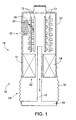
- FIG. 1 shows an actuator in which air enters and exits the housing through the same aperture;
- FIG. 2 shows a one-way valve sealing an intake aperture; and
- FIG. 3 shows a one-way valve sealing an exhaust aperture.
-
- An adaptive suspension system for a motor vehicle includes four
electromagnetic actuators 10 mounted in each of the four corners of the motor vehicle. In response to signals from a controller, theactuators 10 apply forces to dynamically control the separation between a vehicle chassis and the road surface. These forces collectively control the attitude of the chassis relative to the road surface. - An
exemplary actuator 10, which is shown in FIG. 1, converts electrical energy into mechanical energy in response to a signal provided by a controller (not shown). This signal is received by components mounted oncircuit boards 12 con tained within theactuator 10. In response to the control signal, components on thecircuit boards 12 cooperate to generate a current throughcoils 14 that are disposed to magnetically couple to amagnetic armature 16. Thecoils 14 may be further surrounded by ferrous materials such as steel. This current causes thearmature 16 to move along a longitudinal axis of thecoils 14. The controller may be inside or outside the enclosure. Asuitable actuator 10 is that disclosed in U.S. Patent 4,981,309, the contents of which are incorporated herein by reference. - The illustrated
actuator 10 is intended to operate in an environment laden with dust, moisture, pieces of flying gravel, and occasional animal parts. To enable reliable operation in such a harsh environment, theactuator 10 is provided with aprotective housing 18 that encloses thecircuit boards 12, thecoils 14, and thearmature 16. - An
upper portion 20 of thehousing 18 forms a rigid bell that protects thecircuit boards 12 and thecoils 14. The bell has anopening 22 that is attached to a flexiblelower portion 24 of thehousing 18. Astop plate 26 integrated with thearmature 16 is coupled to one end of the flexiblelower portion 24. The upper andlower portions lower portion 24 of thehousing 18 is axially flexible. In the illustrated embodiment, thelower portion 24 includes bellows that expand and contract in response to axial movement of thearmature 16. - As a result of ohmic losses, the current flowing in the
coils 14 and in the various electronic components on thecircuit boards 12 generate heat. Because these heat-generating elements are enclosed in thehousing 18, the temperature within thehousing 18 may rise to levels that might cause premature failure of components. - As the
armature 16 moves downward, in an intake stroke, the bellows expand and draw cool air through aninner aperture 28 and anouter aperture 30 separated by a labyrinth occupied by afilter 32. Preferably, theinner aperture 28 is adjacent to thecircuit boards 12, so that the cool filtered air passes immediately over thecircuit boards 12. As thearmature 16 moves upward, in an exhaust stroke, the bellows contract, forcing warm air out though the inner andouter apertures - As shown in FIG. 1, the
outer aperture 30 is below theinner aperture 28. This relationship enables any water that enters or condenses within the labyrinth to drip outward, away from thehousing 18. - In the embodiment shown in FIG. 1, air enters and exits the
housing 18 through thesame apertures housing 18. When it does so, it will tend to collect on thestop plate 26. Second, during the exha ust stroke, the bellows blow across thecircuit boards 12, air that has already passed over thecircuit boards 12 at least once. Such air will generally be warmer than the air drawn in from the outside during the intake stroke. As a result, the average temperature of air passing over thecircuit boards 12 is higher than it would be if only fresh outside air passed over thecircuit boards 12. These disadvantages are overcome in the embodiment shown in FIGS. 2 and 3, in which air enters and exits thehousing 18 through different apertures. - FIG. 2 shows an
inner aperture 28 that is sealed by an intake valve 34. The intake valve 34 is a one-way flap or check valve that is oriented to allow outside air to enter thehousing 18 but to prevent air from exiting thehousing 18. Conversely, an exhaust aperture in thestop plate 26 is sealed by an exhaust valve, shown in FIG. 3. The exhaust valve, like the intake valve 34, is a one-way flap, or check valve. However, its orientation is such that air is permitted to exit, but not to enter, thehousing 18. The placement of the exhaust aperture at thestop plate 26 is advantageous because thestop plate 26 is at the lowest point on theactuator 10. As a result, gravity causes any accumulated moisture to collect on thestop palate 26 and to drain out of thehousing 18 through the exhaust aperture. However, the exhaust aperture need not be at the actuator's lowest point. - Alternatively, the
housing 18, can be formed by having thearmature 16 and thestop plate 26 function as a piston arm and piston head respectively. Thestop plate 26 would then fit snugly inside a cylinder. In this case, the interior volume of the housing, which is defined by walls of the cylinder and the stop plate, again changes volume in response to movement of thearmature 16. - In a
housing 18 having an intake valve 34 and anexhaust valve 36 as shown in FIGS. 2 and 3, the intake stroke draws air into thehousing 18 and across thecircuit boards 12, as discussed in connection with FIG. 1. However, during the exhaust stroke, air exits thehousing 18 through the exhaust aperture. - The configuration shown in FIGS. 2 and 3, in which air enters and exits the
housing 18 through different apertures, offers at least two advantages. First the average air temperature at thecircuit boards 12 will be lower. As a result, the air will cool thecircuit boards 12 more effectively. Second any water condensing inside thehousing 18 will be able to exit thehousing 18 through the exhaust aperture. This expulsion will occur automatically during the exhaust stroke, as theexhaust valve 36 opens. - In the embodiments described herein, the interior volume of the
housing 18 changes because bellows expand and contract in response to movement of thearmature 16. However, other structures can be used to change the volume of the housing. For example, thearmature 16 may be coupled to a first rigid cylinder that slides into and out of a second rigid cylinder. In this case, the volume enclosed by the first and second cylinders would also change in response to movement of the armature. - It is to be understood that while the invention has been described in conjunction with the detailed description thereof, the foregoing description is intended to illustrate and not limit the scope of the invention, which is defined by the scope of the appended claims. Other aspects, advantages, and modifications are within the scope of the following claims.
Claims (39)
- An actuator for an active suspension system, the actuator comprising:an armature; anda housing enclosing the armature, the housing having an interior volume that varies in response to movement of the armature, the housing defining a first aperture through which air passes in response to movement of the armature.
- The actuator of claim 1, further comprising electronic circuitry for effecting movement of the armature, the electronic circuitry disposed within the interior volume of the housing.
- The actuator of claim 1, wherein the housing further defines a wall forming a second aperture through which air passes in response to movement of the armature.
- The actuator of claim 3, wherein the first and second apertures are configured such that, in response to a first movement of the armature, air is drawn into the interior through the first and second apertures, and in response to a second movement of the armature, air is expelled from the interior through the first and second apertures.
- The actuator of claim 3, wherein the first and second apertures are configured such that, in response to a first movement of the armature, air is drawn into the interior through the first aperture, and in response to a second movement of the armature, air is expelled from the interior through the second aperture.
- The actuator of claim 3, wherein the housi ng defines walls defining a labyrinth extending between the first and second apertures.
- The actuator of claim 6, further comprising a filter disposed in the labyrinth.
- The actuator of claim 3, further comprising:a first one-way valve associated with the first aperture, the first one-way valve being configured to allow admission of air into the housing interior through the first aperture.
- The actuator of claim 8, further comprising:a second one-way valve associated with the second aperture, th e second one-way valve being configured to allow expulsion of air from the housing interior through the second aperture.
- The actuator of claim 9, wherein the second one-way valve is disposed to drain fluid from the interior volume of the housing.
- The actuator of claim 1, wherein the housing comprises:wherein a volume enclosed by the first and second portions varies in response to movement of the armature.a first portion coupled to the armature; anda second portion coupled to the first portion,
- The actuator of claim 11, wherein the first portion comprises bellows.
- The actuator of claim 12, further comprising a stop plate defining a second aperture, the stop plate being coupled to the bellows.
- The actuator of claim 12, wherein the first portion further comprises a stop plate configured to move in response to movement of the armature, whereby the stop plate couples the first portion to the armature.
- The actuator of claim 14, wherein the stop plate defines a second aperture through which air passes in response to movement of the armature.
- The actuator of claim 12, wherein the armature comprises a stop plate coupled to the bellows.
- The actuator of claim 16, wherein the stop plate defines a second aperture through which air passes in response to movement of the armature.
- The actuator of claim 17, further comprising a
a first one-way valve associated with the first aperture, the first one -way valve being configured to allow admission of air into the housing interior through the first aperture; and
a second one-way valve associated with the second aperture, the second one-way valve being configured to allow expulsion of air from the housing interior through the second aperture. - The actuator of claim 11, wherein the first portion comprises a flexible portion joined to the second portion.
- The actuator of claim 19, wherein the second portion comprises a rigid portion.
- The actuator of claim 11, wherein the first portion comprises a moveable portion.
- The actuator of claim 21, wherein the first portion comprises a first cylinder and the second portion comprises a second cylinder, the first and second cylinder having different radii such that one of the first and second cylinders can slide into the other in response to movement of the armature.
- The actuator of claim 21, wherein the first portion comprises a piston head and the second portion comprises a cylinder sized to accommodate the piston head, the piston head and the cylinder defining a volume that changes in response to movement of the armature.
- The actuator of claim 11, wherein the first portion defines a second aperture through which air passes in response to movement of the armature.
- The actuator of claim 24, further comprising:a first one-way valve associated with the first aperture, the first one-way valve being configured to allow admission of air into the housing interior through the first aperture; anda second one-way valve associated with the second aperture, the second one-way valve being configured to allow expulsion of air from the housing interior through the second aperture.
- The actuator of claim 11, wherein the second portion:defines a second aperture through which air passes in response to movement of the armature; anddefines the first aperture.
- The actuator of claim 26, wherein the second portion defines a labyrinth between the first and second apertures.
- A motor vehicle having an active suspension system, the active suspension system including an actuator as recited in claim 1.
- An active suspension system comprising an actuator as recited in claim 1.
- A motor vehicle comprising an active suspension system as recited in claim 29.
- A method for cooling components of an actuator in an active suspension sys tem, the method comprising:changing an interior volume of the housing to draw air into the housing and to pass air over the components of the actuator; andchanging the interior volume to expel air from the housing.
- The method of claim 31, wherein changing an interior volume comprises increasing the interior volume.
- The method of claim 32, wherein changing the interior volume comprises decreasing the interior volume.
- The method of claim 33, wherein increasing the interior volume comprises cau sing air to be drawn into the housing through a first aperture and decreasing the interior volume comprises causing air to be expelled from the housing through the first aperture.
- The method of claim 33, wherein increasing the interior volume comprise s causing air to be drawn into the housing through a first aperture, and wherein decreasing the interior volume comprises causing air to be expelled from the housing through a second aperture.
- The method of claim 35, wherein causing air to be drawn into the housing comprises causing a first one-way valve sealing the first aperture to open, and causing air to be expelled from the housing comprises causing a second one-way valve sealing the second aperture to open.
- The method of claim 35, wherein decreasing the interior volume further comprises causing liquid to be expelled from the housing through the second aperture.
- The method of claim 33, wherein increasing the interior volume and decreasing the interior volume each comprise passing current through a coil in the housing, the actuator having a moveable armature coupled to a portion of the housing.
- A housing for enclosing an armature, the housing having an interior volume that varies in response to movement of the aperture, the variation of interior volume causing passage of air through an aperture defined by the housing.
Applications Claiming Priority (2)
| Application Number | Priority Date | Filing Date | Title |
|---|---|---|---|
| US870521 | 1992-04-17 | ||
| US10/870,521 US7202577B2 (en) | 2004-06-17 | 2004-06-17 | Self-cooling actuator |
Publications (2)
| Publication Number | Publication Date |
|---|---|
| EP1607250A1 true EP1607250A1 (en) | 2005-12-21 |
| EP1607250B1 EP1607250B1 (en) | 2010-01-13 |
Family
ID=34940041
Family Applications (1)
| Application Number | Title | Priority Date | Filing Date |
|---|---|---|---|
| EP05104711A Ceased EP1607250B1 (en) | 2004-06-17 | 2005-06-01 | Self cooling actuator |
Country Status (5)
| Country | Link |
|---|---|
| US (1) | US7202577B2 (en) |
| EP (1) | EP1607250B1 (en) |
| JP (1) | JP2006014588A (en) |
| CN (1) | CN100503289C (en) |
| DE (1) | DE602005018857D1 (en) |
Cited By (2)
| Publication number | Priority date | Publication date | Assignee | Title |
|---|---|---|---|---|
| EP2966758A1 (en) * | 2014-07-08 | 2016-01-13 | Siemens Aktiengesellschaft | Protection system for an electric machine |
| DE102017120172A1 (en) * | 2017-09-01 | 2019-03-07 | Thyssenkrupp Ag | Filter device and fastening means with such a filter device |
Families Citing this family (37)
| Publication number | Priority date | Publication date | Assignee | Title |
|---|---|---|---|---|
| EP1936187B1 (en) * | 2006-12-22 | 2011-09-28 | F.LLI Tabanelli S.N.C. Di Tabanelli Paolo & C. | Multiple membrane pump for food liquids and the like |
| JP2009132280A (en) * | 2007-11-30 | 2009-06-18 | Equos Research Co Ltd | Camber angle adjustment mechanism |
| US8839920B2 (en) | 2008-04-17 | 2014-09-23 | Levant Power Corporation | Hydraulic energy transfer |
| US8076877B2 (en) * | 2008-10-17 | 2011-12-13 | Oteman David G | System and method for controlling power balance in an electrical/mechanical system |
| US8561756B2 (en) | 2012-02-17 | 2013-10-22 | Bose Corporation | Acoustic ports aligned to create free convective airflow |
| US8798308B2 (en) | 2012-02-21 | 2014-08-05 | Bose Corporation | Convective airflow using a passive radiator |
| CN103573901B (en) * | 2012-08-04 | 2015-11-25 | 李天维 | Self cooled damper |
| US9174508B2 (en) | 2013-03-15 | 2015-11-03 | Levant Power Corporation | Active vehicle suspension |
| US9809078B2 (en) | 2013-03-15 | 2017-11-07 | ClearMotion, Inc. | Multi-path fluid diverter valve |
| US9702349B2 (en) | 2013-03-15 | 2017-07-11 | ClearMotion, Inc. | Active vehicle suspension system |
| EP4450845A3 (en) | 2013-03-15 | 2025-01-01 | ClearMotion, Inc. | Active vehicle suspension improvements |
| EP3825156A1 (en) | 2013-04-23 | 2021-05-26 | ClearMotion, Inc. | Active suspension with structural actuator |
| JP5998102B2 (en) * | 2013-06-03 | 2016-09-28 | 本田技研工業株式会社 | Telescopic actuator |
| US9702424B2 (en) | 2014-10-06 | 2017-07-11 | ClearMotion, Inc. | Hydraulic damper, hydraulic bump-stop and diverter valve |
| US10300760B1 (en) | 2015-03-18 | 2019-05-28 | Apple Inc. | Fully-actuated suspension system |
| DE102017102668A1 (en) * | 2017-02-10 | 2018-08-16 | Dr. Ing. H.C. F. Porsche Aktiengesellschaft | Method and device for monitoring a temperature of a battery system |
| US10814690B1 (en) | 2017-04-18 | 2020-10-27 | Apple Inc. | Active suspension system with energy storage device |
| CN110997362B (en) | 2017-05-08 | 2023-07-28 | 苹果公司 | active suspension system |
| US10899340B1 (en) | 2017-06-21 | 2021-01-26 | Apple Inc. | Vehicle with automated subsystems |
| US11173766B1 (en) | 2017-09-07 | 2021-11-16 | Apple Inc. | Suspension system with locking structure |
| US11065931B1 (en) | 2017-09-15 | 2021-07-20 | Apple Inc. | Active suspension system |
| US11124035B1 (en) | 2017-09-25 | 2021-09-21 | Apple Inc. | Multi-stage active suspension actuator |
| US10960723B1 (en) | 2017-09-26 | 2021-03-30 | Apple Inc. | Wheel-mounted suspension actuators |
| US10425739B2 (en) * | 2017-10-03 | 2019-09-24 | Bose Corporation | Acoustic deflector with convective cooling |
| US11285773B1 (en) | 2018-09-12 | 2022-03-29 | Apple Inc. | Control system |
| US11634167B1 (en) | 2018-09-14 | 2023-04-25 | Apple Inc. | Transmitting axial and rotational movement to a hub |
| KR102595433B1 (en) * | 2018-12-20 | 2023-10-31 | 에이치엘만도 주식회사 | A Cooling Apparatus Using a Vehicle Suspension |
| US11345209B1 (en) | 2019-06-03 | 2022-05-31 | Apple Inc. | Suspension systems |
| CN112054645B (en) * | 2019-06-07 | 2024-11-15 | 美蓓亚三美株式会社 | Vibration actuators and electronic devices |
| US11179991B1 (en) | 2019-09-23 | 2021-11-23 | Apple Inc. | Suspension systems |
| US11938922B1 (en) | 2019-09-23 | 2024-03-26 | Apple Inc. | Motion control system |
| US11707961B1 (en) | 2020-04-28 | 2023-07-25 | Apple Inc. | Actuator with reinforcing structure for torsion resistance |
| US11828339B1 (en) | 2020-07-07 | 2023-11-28 | Apple Inc. | Vibration control system |
| DE102021102352B4 (en) * | 2021-02-02 | 2026-03-12 | Audi Aktiengesellschaft | Method for operating at least one electromechanical actuator of a motor vehicle and motor vehicle |
| CN117396339A (en) | 2021-06-07 | 2024-01-12 | 苹果公司 | mass damper system |
| US12251973B2 (en) | 2022-06-10 | 2025-03-18 | Apple Inc. | Vibration absorber |
| US12168375B1 (en) | 2023-01-26 | 2024-12-17 | Apple Inc. | Motion control system |
Citations (4)
| Publication number | Priority date | Publication date | Assignee | Title |
|---|---|---|---|---|
| JPH04159113A (en) * | 1990-09-19 | 1992-06-02 | Mazda Motor Corp | Magnetic suspension device of automobile |
| EP0604028A1 (en) * | 1992-12-21 | 1994-06-29 | Ford Motor Company Limited | Suspension damper with integrated controls |
| US5573088A (en) * | 1994-05-10 | 1996-11-12 | Daniels; John J. | Controllable resistance device and force dampener, and vehicle utilizing the same |
| DE10205771A1 (en) * | 2002-02-12 | 2003-08-21 | Bayerische Motoren Werke Ag | Active motor vehicle wheel suspension arrangement uses a linear motor which has a cooling system |
Family Cites Families (13)
| Publication number | Priority date | Publication date | Assignee | Title |
|---|---|---|---|---|
| US3805099A (en) * | 1973-04-09 | 1974-04-16 | Robertshaw Controls Co | Linear actuator |
| JPS56157238A (en) * | 1980-05-07 | 1981-12-04 | Fanuc Ltd | Rotary motor |
| US4889039A (en) * | 1988-10-17 | 1989-12-26 | Miller Bernard F | Gas compressor with labyrinth sealing and active magnetic bearings |
| KR930011735B1 (en) * | 1991-07-09 | 1993-12-18 | 손동훈 | Low Frequency Sound Pressure Generator |
| JPH0672709B2 (en) * | 1992-10-21 | 1994-09-14 | 株式会社東芝 | Air conditioner outdoor unit |
| DE19511114C1 (en) * | 1995-03-25 | 1996-08-29 | Grundfos As | Electric motor |
| IT1289322B1 (en) * | 1996-01-19 | 1998-10-02 | Carlo Alberto Zenobi | DEVICE FOR OBTAINING ELECTRICITY FROM THE DYNAMIC ACTIONS ARISING FROM THE RELATIVE MOTION BETWEEN VEHICLES AND THE GROUND |
| JP3525685B2 (en) * | 1997-07-14 | 2004-05-10 | 住友電気工業株式会社 | Voice coil motor |
| JP2000356236A (en) * | 1999-06-14 | 2000-12-26 | Ryokichi Tsuchiya | Cooling device for reciprocating piston type damper |
| JP2001263415A (en) * | 2000-03-17 | 2001-09-26 | Canon Inc | Active vibration isolator and compound actuator for vibration isolator |
| JP2002257189A (en) * | 2001-02-28 | 2002-09-11 | Tokico Ltd | Electromagnetic suspension device |
| JP4706133B2 (en) * | 2001-06-15 | 2011-06-22 | 株式会社豊田自動織機 | Control device cooling structure and counterbalance forklift truck in industrial vehicles |
| JP3974456B2 (en) * | 2002-06-05 | 2007-09-12 | ヤンマー株式会社 | Power generator |
-
2004
- 2004-06-17 US US10/870,521 patent/US7202577B2/en not_active Expired - Lifetime
-
2005
- 2005-06-01 DE DE602005018857T patent/DE602005018857D1/en not_active Expired - Lifetime
- 2005-06-01 EP EP05104711A patent/EP1607250B1/en not_active Ceased
- 2005-06-10 CN CNB2005100763530A patent/CN100503289C/en not_active Expired - Fee Related
- 2005-06-17 JP JP2005177125A patent/JP2006014588A/en active Pending
Patent Citations (4)
| Publication number | Priority date | Publication date | Assignee | Title |
|---|---|---|---|---|
| JPH04159113A (en) * | 1990-09-19 | 1992-06-02 | Mazda Motor Corp | Magnetic suspension device of automobile |
| EP0604028A1 (en) * | 1992-12-21 | 1994-06-29 | Ford Motor Company Limited | Suspension damper with integrated controls |
| US5573088A (en) * | 1994-05-10 | 1996-11-12 | Daniels; John J. | Controllable resistance device and force dampener, and vehicle utilizing the same |
| DE10205771A1 (en) * | 2002-02-12 | 2003-08-21 | Bayerische Motoren Werke Ag | Active motor vehicle wheel suspension arrangement uses a linear motor which has a cooling system |
Non-Patent Citations (1)
| Title |
|---|
| PATENT ABSTRACTS OF JAPAN vol. 016, no. 452 (M - 1313) 21 September 1992 (1992-09-21) * |
Cited By (6)
| Publication number | Priority date | Publication date | Assignee | Title |
|---|---|---|---|---|
| EP2966758A1 (en) * | 2014-07-08 | 2016-01-13 | Siemens Aktiengesellschaft | Protection system for an electric machine |
| WO2016005217A1 (en) * | 2014-07-08 | 2016-01-14 | Siemens Aktiengesellschaft | Protection system for an electrical machine |
| US10601278B2 (en) | 2014-07-08 | 2020-03-24 | Siemens Aktiengesellschaft | Protection system for an electrical machine |
| DE102017120172A1 (en) * | 2017-09-01 | 2019-03-07 | Thyssenkrupp Ag | Filter device and fastening means with such a filter device |
| US11471809B2 (en) | 2017-09-01 | 2022-10-18 | Thyssenkrupp Bilstein Gmbh | Filter device and fixing means comprising a filter device of this type |
| DE102017120172B4 (en) | 2017-09-01 | 2026-03-19 | Thyssenkrupp Ag | Filter device and fastening means with such filter device |
Also Published As
| Publication number | Publication date |
|---|---|
| CN100503289C (en) | 2009-06-24 |
| EP1607250B1 (en) | 2010-01-13 |
| CN1709729A (en) | 2005-12-21 |
| US20050280318A1 (en) | 2005-12-22 |
| US7202577B2 (en) | 2007-04-10 |
| JP2006014588A (en) | 2006-01-12 |
| DE602005018857D1 (en) | 2010-03-04 |
Similar Documents
| Publication | Publication Date | Title |
|---|---|---|
| US7202577B2 (en) | Self-cooling actuator | |
| EP1790505B1 (en) | Active vehicle suspension system | |
| DE10141397B4 (en) | Motor driven compressor | |
| US9366309B2 (en) | Engine mount for a motor vehicle | |
| US8449767B2 (en) | Oil reservoir comprising an oil filter | |
| US8907663B2 (en) | Height sensor module for a vehicle with sealing structure | |
| CN106122358B (en) | Active engine mount | |
| JPS63162997A (en) | Pump assembly | |
| CN104019180A (en) | Electromagnetic suspension apparatus | |
| CN105811640A (en) | Motor assembly | |
| JP2002302051A (en) | Protective cover | |
| CN117656742B (en) | Suspension device and vehicle with same | |
| CN109421873A (en) | Hydraulic operation device | |
| JP2006014588A5 (en) | ||
| CN109667880A (en) | Hydraulic mount element | |
| WO2018070281A1 (en) | Linear compressor and device equipped with same | |
| EP1046526A3 (en) | Air condenser, coolant system, and on vehicle air conditioning system | |
| JPH11102813A (en) | Electromagnetic actuator | |
| US20090009009A1 (en) | Active vibration isolation support system | |
| JP3160008B2 (en) | Working cylinder | |
| JPH06323769A (en) | Device capable of being cooled for accepting electrical structural group | |
| EP1219858A1 (en) | Shock absorber using a hydraulic fluid and a magnetorheological fluid | |
| JP2003341497A (en) | Brake liquid pressure control device and piston type reserver | |
| JPH09170674A (en) | solenoid valve | |
| JP2005214359A (en) | Linear motor |
Legal Events
| Date | Code | Title | Description |
|---|---|---|---|
| PUAI | Public reference made under article 153(3) epc to a published international application that has entered the european phase |
Free format text: ORIGINAL CODE: 0009012 |
|
| AK | Designated contracting states |
Kind code of ref document: A1 Designated state(s): AT BE BG CH CY CZ DE DK EE ES FI FR GB GR HU IE IS IT LI LT LU MC NL PL PT RO SE SI SK TR |
|
| AX | Request for extension of the european patent |
Extension state: AL BA HR LV MK YU |
|
| 17P | Request for examination filed |
Effective date: 20060321 |
|
| AKX | Designation fees paid |
Designated state(s): DE GB |
|
| 17Q | First examination report despatched |
Effective date: 20071108 |
|
| GRAP | Despatch of communication of intention to grant a patent |
Free format text: ORIGINAL CODE: EPIDOSNIGR1 |
|
| GRAS | Grant fee paid |
Free format text: ORIGINAL CODE: EPIDOSNIGR3 |
|
| GRAA | (expected) grant |
Free format text: ORIGINAL CODE: 0009210 |
|
| AK | Designated contracting states |
Kind code of ref document: B1 Designated state(s): DE GB |
|
| REG | Reference to a national code |
Ref country code: GB Ref legal event code: FG4D |
|
| REF | Corresponds to: |
Ref document number: 602005018857 Country of ref document: DE Date of ref document: 20100304 Kind code of ref document: P |
|
| PLBE | No opposition filed within time limit |
Free format text: ORIGINAL CODE: 0009261 |
|
| STAA | Information on the status of an ep patent application or granted ep patent |
Free format text: STATUS: NO OPPOSITION FILED WITHIN TIME LIMIT |
|
| 26N | No opposition filed |
Effective date: 20101014 |
|
| PGFP | Annual fee paid to national office [announced via postgrant information from national office to epo] |
Ref country code: GB Payment date: 20150629 Year of fee payment: 11 |
|
| GBPC | Gb: european patent ceased through non-payment of renewal fee |
Effective date: 20160601 |
|
| PG25 | Lapsed in a contracting state [announced via postgrant information from national office to epo] |
Ref country code: GB Free format text: LAPSE BECAUSE OF NON-PAYMENT OF DUE FEES Effective date: 20160601 |
|
| PGFP | Annual fee paid to national office [announced via postgrant information from national office to epo] |
Ref country code: DE Payment date: 20200629 Year of fee payment: 16 |
|
| REG | Reference to a national code |
Ref country code: DE Ref legal event code: R119 Ref document number: 602005018857 Country of ref document: DE |
|
| PG25 | Lapsed in a contracting state [announced via postgrant information from national office to epo] |
Ref country code: DE Free format text: LAPSE BECAUSE OF NON-PAYMENT OF DUE FEES Effective date: 20220101 |