EP1607130A1 - Sealed honeycomb structure and method of producing the same - Google Patents
Sealed honeycomb structure and method of producing the same Download PDFInfo
- Publication number
- EP1607130A1 EP1607130A1 EP04722011A EP04722011A EP1607130A1 EP 1607130 A1 EP1607130 A1 EP 1607130A1 EP 04722011 A EP04722011 A EP 04722011A EP 04722011 A EP04722011 A EP 04722011A EP 1607130 A1 EP1607130 A1 EP 1607130A1
- Authority
- EP
- European Patent Office
- Prior art keywords
- plugged
- honeycomb structure
- plugging
- face
- partition walls
- Prior art date
- Legal status (The legal status is an assumption and is not a legal conclusion. Google has not performed a legal analysis and makes no representation as to the accuracy of the status listed.)
- Granted
Links
Images




Classifications
-
- B—PERFORMING OPERATIONS; TRANSPORTING
- B01—PHYSICAL OR CHEMICAL PROCESSES OR APPARATUS IN GENERAL
- B01D—SEPARATION
- B01D46/00—Filters or filtering processes specially modified for separating dispersed particles from gases or vapours
- B01D46/0001—Making filtering elements
-
- B—PERFORMING OPERATIONS; TRANSPORTING
- B01—PHYSICAL OR CHEMICAL PROCESSES OR APPARATUS IN GENERAL
- B01D—SEPARATION
- B01D46/00—Filters or filtering processes specially modified for separating dispersed particles from gases or vapours
- B01D46/24—Particle separators, e.g. dust precipitators, using rigid hollow filter bodies
- B01D46/2403—Particle separators, e.g. dust precipitators, using rigid hollow filter bodies characterised by the physical shape or structure of the filtering element
- B01D46/2418—Honeycomb filters
- B01D46/2451—Honeycomb filters characterized by the geometrical structure, shape, pattern or configuration or parameters related to the geometry of the structure
- B01D46/2474—Honeycomb filters characterized by the geometrical structure, shape, pattern or configuration or parameters related to the geometry of the structure of the walls along the length of the honeycomb
-
- B—PERFORMING OPERATIONS; TRANSPORTING
- B01—PHYSICAL OR CHEMICAL PROCESSES OR APPARATUS IN GENERAL
- B01D—SEPARATION
- B01D46/00—Filters or filtering processes specially modified for separating dispersed particles from gases or vapours
- B01D46/24—Particle separators, e.g. dust precipitators, using rigid hollow filter bodies
- B01D46/2403—Particle separators, e.g. dust precipitators, using rigid hollow filter bodies characterised by the physical shape or structure of the filtering element
- B01D46/2418—Honeycomb filters
- B01D46/2425—Honeycomb filters characterized by parameters related to the physical properties of the honeycomb structure material
- B01D46/24494—Thermal expansion coefficient, heat capacity or thermal conductivity
-
- B—PERFORMING OPERATIONS; TRANSPORTING
- B01—PHYSICAL OR CHEMICAL PROCESSES OR APPARATUS IN GENERAL
- B01D—SEPARATION
- B01D46/00—Filters or filtering processes specially modified for separating dispersed particles from gases or vapours
- B01D46/24—Particle separators, e.g. dust precipitators, using rigid hollow filter bodies
- B01D46/2403—Particle separators, e.g. dust precipitators, using rigid hollow filter bodies characterised by the physical shape or structure of the filtering element
- B01D46/2418—Honeycomb filters
- B01D46/2451—Honeycomb filters characterized by the geometrical structure, shape, pattern or configuration or parameters related to the geometry of the structure
- B01D46/2459—Honeycomb filters characterized by the geometrical structure, shape, pattern or configuration or parameters related to the geometry of the structure of the plugs
-
- B—PERFORMING OPERATIONS; TRANSPORTING
- B01—PHYSICAL OR CHEMICAL PROCESSES OR APPARATUS IN GENERAL
- B01D—SEPARATION
- B01D46/00—Filters or filtering processes specially modified for separating dispersed particles from gases or vapours
- B01D46/24—Particle separators, e.g. dust precipitators, using rigid hollow filter bodies
- B01D46/2403—Particle separators, e.g. dust precipitators, using rigid hollow filter bodies characterised by the physical shape or structure of the filtering element
- B01D46/2418—Honeycomb filters
- B01D46/2451—Honeycomb filters characterized by the geometrical structure, shape, pattern or configuration or parameters related to the geometry of the structure
- B01D46/247—Honeycomb filters characterized by the geometrical structure, shape, pattern or configuration or parameters related to the geometry of the structure of the cells
-
- B—PERFORMING OPERATIONS; TRANSPORTING
- B01—PHYSICAL OR CHEMICAL PROCESSES OR APPARATUS IN GENERAL
- B01D—SEPARATION
- B01D46/00—Filters or filtering processes specially modified for separating dispersed particles from gases or vapours
- B01D46/24—Particle separators, e.g. dust precipitators, using rigid hollow filter bodies
- B01D46/2403—Particle separators, e.g. dust precipitators, using rigid hollow filter bodies characterised by the physical shape or structure of the filtering element
- B01D46/2418—Honeycomb filters
- B01D46/2451—Honeycomb filters characterized by the geometrical structure, shape, pattern or configuration or parameters related to the geometry of the structure
- B01D46/2476—Monolithic structures
-
- B—PERFORMING OPERATIONS; TRANSPORTING
- B01—PHYSICAL OR CHEMICAL PROCESSES OR APPARATUS IN GENERAL
- B01D—SEPARATION
- B01D46/00—Filters or filtering processes specially modified for separating dispersed particles from gases or vapours
- B01D46/24—Particle separators, e.g. dust precipitators, using rigid hollow filter bodies
- B01D46/2403—Particle separators, e.g. dust precipitators, using rigid hollow filter bodies characterised by the physical shape or structure of the filtering element
- B01D46/2418—Honeycomb filters
- B01D46/2451—Honeycomb filters characterized by the geometrical structure, shape, pattern or configuration or parameters related to the geometry of the structure
- B01D46/2482—Thickness, height, width, length or diameter
-
- B—PERFORMING OPERATIONS; TRANSPORTING
- B28—WORKING CEMENT, CLAY, OR STONE
- B28B—SHAPING CLAY OR OTHER CERAMIC COMPOSITIONS; SHAPING SLAG; SHAPING MIXTURES CONTAINING CEMENTITIOUS MATERIAL, e.g. PLASTER
- B28B11/00—Apparatus or processes for treating or working the shaped or preshaped articles
- B28B11/003—Apparatus or processes for treating or working the shaped or preshaped articles the shaping of preshaped articles, e.g. by bending
- B28B11/006—Making hollow articles or partly closed articles
-
- F—MECHANICAL ENGINEERING; LIGHTING; HEATING; WEAPONS; BLASTING
- F01—MACHINES OR ENGINES IN GENERAL; ENGINE PLANTS IN GENERAL; STEAM ENGINES
- F01N—GAS-FLOW SILENCERS OR EXHAUST APPARATUS FOR MACHINES OR ENGINES IN GENERAL; GAS-FLOW SILENCERS OR EXHAUST APPARATUS FOR INTERNAL-COMBUSTION ENGINES
- F01N3/00—Exhaust or silencing apparatus having means for purifying, rendering innocuous, or otherwise treating exhaust
- F01N3/02—Exhaust or silencing apparatus having means for purifying, rendering innocuous, or otherwise treating exhaust for cooling, or for removing solid constituents of, exhaust
- F01N3/021—Exhaust or silencing apparatus having means for purifying, rendering innocuous, or otherwise treating exhaust for cooling, or for removing solid constituents of, exhaust by means of filters
- F01N3/022—Exhaust or silencing apparatus having means for purifying, rendering innocuous, or otherwise treating exhaust for cooling, or for removing solid constituents of, exhaust by means of filters characterised by specially adapted filtering structure, e.g. honeycomb, mesh or fibrous
- F01N3/0222—Exhaust or silencing apparatus having means for purifying, rendering innocuous, or otherwise treating exhaust for cooling, or for removing solid constituents of, exhaust by means of filters characterised by specially adapted filtering structure, e.g. honeycomb, mesh or fibrous the structure being monolithic, e.g. honeycombs
-
- B—PERFORMING OPERATIONS; TRANSPORTING
- B01—PHYSICAL OR CHEMICAL PROCESSES OR APPARATUS IN GENERAL
- B01D—SEPARATION
- B01D46/00—Filters or filtering processes specially modified for separating dispersed particles from gases or vapours
- B01D46/24—Particle separators, e.g. dust precipitators, using rigid hollow filter bodies
- B01D46/2403—Particle separators, e.g. dust precipitators, using rigid hollow filter bodies characterised by the physical shape or structure of the filtering element
- B01D46/2418—Honeycomb filters
- B01D46/2498—The honeycomb filter being defined by mathematical relationships
-
- Y—GENERAL TAGGING OF NEW TECHNOLOGICAL DEVELOPMENTS; GENERAL TAGGING OF CROSS-SECTIONAL TECHNOLOGIES SPANNING OVER SEVERAL SECTIONS OF THE IPC; TECHNICAL SUBJECTS COVERED BY FORMER USPC CROSS-REFERENCE ART COLLECTIONS [XRACs] AND DIGESTS
- Y02—TECHNOLOGIES OR APPLICATIONS FOR MITIGATION OR ADAPTATION AGAINST CLIMATE CHANGE
- Y02T—CLIMATE CHANGE MITIGATION TECHNOLOGIES RELATED TO TRANSPORTATION
- Y02T10/00—Road transport of goods or passengers
- Y02T10/10—Internal combustion engine [ICE] based vehicles
- Y02T10/12—Improving ICE efficiencies
-
- Y—GENERAL TAGGING OF NEW TECHNOLOGICAL DEVELOPMENTS; GENERAL TAGGING OF CROSS-SECTIONAL TECHNOLOGIES SPANNING OVER SEVERAL SECTIONS OF THE IPC; TECHNICAL SUBJECTS COVERED BY FORMER USPC CROSS-REFERENCE ART COLLECTIONS [XRACs] AND DIGESTS
- Y10—TECHNICAL SUBJECTS COVERED BY FORMER USPC
- Y10S—TECHNICAL SUBJECTS COVERED BY FORMER USPC CROSS-REFERENCE ART COLLECTIONS [XRACs] AND DIGESTS
- Y10S264/00—Plastic and nonmetallic article shaping or treating: processes
- Y10S264/48—Processes of making filters
-
- Y—GENERAL TAGGING OF NEW TECHNOLOGICAL DEVELOPMENTS; GENERAL TAGGING OF CROSS-SECTIONAL TECHNOLOGIES SPANNING OVER SEVERAL SECTIONS OF THE IPC; TECHNICAL SUBJECTS COVERED BY FORMER USPC CROSS-REFERENCE ART COLLECTIONS [XRACs] AND DIGESTS
- Y10—TECHNICAL SUBJECTS COVERED BY FORMER USPC
- Y10S—TECHNICAL SUBJECTS COVERED BY FORMER USPC CROSS-REFERENCE ART COLLECTIONS [XRACs] AND DIGESTS
- Y10S55/00—Gas separation
- Y10S55/05—Methods of making filter
-
- Y—GENERAL TAGGING OF NEW TECHNOLOGICAL DEVELOPMENTS; GENERAL TAGGING OF CROSS-SECTIONAL TECHNOLOGIES SPANNING OVER SEVERAL SECTIONS OF THE IPC; TECHNICAL SUBJECTS COVERED BY FORMER USPC CROSS-REFERENCE ART COLLECTIONS [XRACs] AND DIGESTS
- Y10—TECHNICAL SUBJECTS COVERED BY FORMER USPC
- Y10S—TECHNICAL SUBJECTS COVERED BY FORMER USPC CROSS-REFERENCE ART COLLECTIONS [XRACs] AND DIGESTS
- Y10S55/00—Gas separation
- Y10S55/10—Residue burned
-
- Y—GENERAL TAGGING OF NEW TECHNOLOGICAL DEVELOPMENTS; GENERAL TAGGING OF CROSS-SECTIONAL TECHNOLOGIES SPANNING OVER SEVERAL SECTIONS OF THE IPC; TECHNICAL SUBJECTS COVERED BY FORMER USPC CROSS-REFERENCE ART COLLECTIONS [XRACs] AND DIGESTS
- Y10—TECHNICAL SUBJECTS COVERED BY FORMER USPC
- Y10S—TECHNICAL SUBJECTS COVERED BY FORMER USPC CROSS-REFERENCE ART COLLECTIONS [XRACs] AND DIGESTS
- Y10S55/00—Gas separation
- Y10S55/30—Exhaust treatment
-
- Y—GENERAL TAGGING OF NEW TECHNOLOGICAL DEVELOPMENTS; GENERAL TAGGING OF CROSS-SECTIONAL TECHNOLOGIES SPANNING OVER SEVERAL SECTIONS OF THE IPC; TECHNICAL SUBJECTS COVERED BY FORMER USPC CROSS-REFERENCE ART COLLECTIONS [XRACs] AND DIGESTS
- Y10—TECHNICAL SUBJECTS COVERED BY FORMER USPC
- Y10T—TECHNICAL SUBJECTS COVERED BY FORMER US CLASSIFICATION
- Y10T428/00—Stock material or miscellaneous articles
- Y10T428/24—Structurally defined web or sheet [e.g., overall dimension, etc.]
- Y10T428/24149—Honeycomb-like
Definitions
- the present invention relates to a sealed or plugged honeycomb structure usable for an exhaust gas purification filter, a water treatment filter, and a separation membrane filter and a production method thereof.
- the present invention relates to a plugged honeycomb structure having high strength, adhesion, and thermal shock resistance between partition walls and plugged portions.
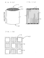
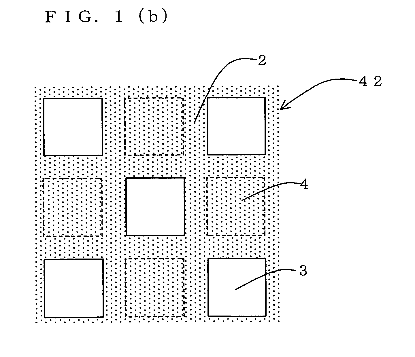
- the honeycomb structure is generally used in the form of a plugged honeycomb structure 1 provided with porous partition walls 2 disposed in such a manner that a plurality of cells 3 are extending from one end face 42 to the other end face 44 in an axial direction and plugged portions 4 disposed in such a manner that each of the cells 3 is plugged at one of the two end faces.
- porous partition walls 2 By employing such a form, fluid to be treated flowing into cells from one end face 42 passes through the porous partition walls 2 and is discharged from the other end face 44 via other cells 3.
- the partition walls 2 function as a filter to trap particulate matter or the like.
- Such a plugged honeycomb structure can generally be produced by producing a honeycomb structure with no plugged portion and subsequently forming plugged portions in predetermined cells.
- a crack is prone to be caused in this portion.
- particulate matter such as soot in exhaust gas sometimes leaks out from a gap between a partition wall and a plugging portion during use of a plugged honeycomb structure as a diesel particulate filter (DPF), and when a DPF is washed by water with high pressure or compressed air in order to discharge outside the DPF particulate matter such as an ash component or a soot component accumulated inside the DPF after the DPF is used for an exhaust gas treatment, a plugged portion is sometimes detached from partition walls to move, and when a plugged portion moves too much, it is sometimes detached from the DPF.
- DPF diesel particulate filter
- a honeycomb filter having a difference in thermal expansion coefficient between a honeycomb structure and plugged portions within a predetermined range, comprising: a mechanism of bonding with a plugging material filling up open pores present in partition walls of a honeycomb structure dried and fired after being formed, and a mechanism of engaging with through holes, and being characterized by substantially not interposing a reaction phase in a contact portion of the ceramic honeycomb structure and the plugged portion (see, for example, JP-A-57-42316).
- the present invention is characterized by providing a plugged honeycomb structure having further improved strength, adhesion, and thermal shock resistance between partition walls and plugged portions and a production method thereof.
- the present inventors found out that by improving affinity between plugged portions and partition walls surrounding the plugged portions, and further unitarily joining plugged portions and partition walls surrounding the plugged portions, intrinsic bonding force can be imparted to the portion between plugged portions and partition walls surrounding the plugged portions; and strength, adhesion, and thermal shock resistance sufficient for maintaining the structure even under severe conditions can be imparted to the structure. They also found out that plugged portions and partition walls surrounding the plugged portions can be unitarily joined by a specific method.
- a plugged honeycomb structure comprising:
- a length of the plugged portions in a longitudinal direction of the cells is ten times as long as a cell pitch or less and that the length of the plugged portions in the longitudinal direction of the cells is two times as long as a thickness of the partition walls or more.
- a method for producing a plugged honeycomb structure comprising:
- the method preferably further comprises a cooling step of cooling the plugged honeycomb structure, and a ratio of thermal expansion coefficient of the plugged portions to thermal expansion coefficient of the partition walls is made to be preferably 0.3 to 3.0%, further preferably 0.5 to 2.0, particularly preferably 0.7 to 1.4 in the temperature range of the cooling in the cooling step.
- the plugging step includes a step of filling the plugging material from one end face of the honeycomb structure with pressurizing inside the cells from the other end face and that the forming raw material contains a binder, and the plugging material contains a binder compatible with the binder contained in the forming raw material.
- the forming raw material contains a binder, and after the forming step, an end face of the honeycomb formed body is heated at 200°C or more to remove at least a part of the binder, followed by conducting the plugging step at the end face.
- the forming raw material is a slurry containing a dispersion medium (C)
- the plugging material is a slurry containing a dispersion medium (D) compatible with the dispersion medium (C) and further preferable that the honeycomb formed body is dried, subsequently, the partition wall-formed body is impregnated with the dispersion medium (C) in the vicinity of an end face, followed by conducting the plugging step at the end face.
- the dispersion medium (C) and the dispersion medium (D) are hydrophobic, and the plugging step is conducted under the condition that temperature of the partition wall-formed body is higher than the normal temperature in the vicinity of an end portion.
- a plugged honeycomb structure and a production method thereof of the present invention will hereinbelow be described in detail on the basis of specific embodiments.
- the present invention is by no means limited to the following embodiments.
- a section orthogonal with an axial direction e.g., axial direction shown in Fig. 1
- a section parallel with an axial direction is referred to as a parallel section.
- a plugged honeycomb structure 1 of the present invention is provided with partition walls 2 disposed so as to form a plurality of cells 3 extending from one end face 42 to the other end face 44 in the axial direction and plugged portions 4 disposed so as to plug the cells 3 at one of the end faces.
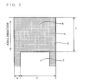
- a plugged honeycomb structure of the present invention is that the plugged portions 4 and the partition wall 2 surrounding the plugged portions are unitarily formed as shown in Fig. 2.
- a possibility that the plugged portions come off in the direction can be reduced.
- the plugged portions can be held in the cells with sufficient strength even without using volume expansion of the plugged portions, a residual stress is not prone to be generated on partition walls surrounding the plugged portions, thereby improving thermal shock resistance. Therefore, even in the case that the honeycomb structure is put under severe temperature conditions, a crack is not prone to be caused in the interface portion 5 and partition walls 2 surrounding the interface portion.
- a possibility that an untreated fluid leaks out from an interface portion 5 between a plugged portion 4 and a partition wall 2 surrounding the plugged portion is markedly reduced.
- plugged portions and partition walls surrounding the plugged portions are unitarily formed
- a plugged honeycomb structure of the present invention has high bonding force between the plugged portions and the partition walls surrounding the plugged portion, it is not required to make the length y of the plugged portions long.
- a thermal stress concentrates more easily to lower thermal shock resistance when the plugged honeycomb structure has high temperature.
- the length y of the plugged portion is preferably 10 times or less, more preferably 5 times or less, of a cell pitch.
- a cell pitch means a length shown by Z in Fig. 2 and a length of one cell as a repeated unit.
- the structure has too large length y of a plugged portion because a partition wall has a small filtration area.
- the length y of a plugged portion is preferably 10% or less, more preferably 5% or less, of a length x in a longitudinal direction of a cell shown in Fig. 1(a).
- the length y of a plugged portion is preferably 2 times or more, more preferably 4 times or more, the thickness of partition walls W.
- the above lower limit of a length of a plugged portion does not apply to this case.
- a plugged honeycomb structure of the present invention there is no particular limitation to a shape or a material as long as it has partition walls 2 disposed so as to form a plurality of cells 3 extending from one end face 42 to the other end face 44 and plugged portions 4 disposed so as to plug the cells 3 at one of the end faces, for example, as shown in Figs. 1(a) to 1(c).
- a shape of an orthogonal section of a plugged honeycomb structure can suitably be selected according to use or a place where the structure is placed and is, for example, a circle, an ellipse, a racetrack shape, or a quadrangle.
- a shape of an orthogonal section of a cell can be, for example, a polygon such as a triangle, a quadrangle, and a hexagon, a circle, or a substantial circle such as an ellipse.
- a cell density can be made to be, for example, 6 to 2000 cell/inch 2 (0.9 to 311 cell/cm 2 ), preferably about 50 to 1000 cell/inch 2 (7.8 to 155 cell/cm 2 ).
- it is preferable that adjacent cells have plugged portions 4 on mutually opposite end faces, and the plugged portions are disposed so that each of the end faces 42, 44 forms a checkerwise pattern.
- a material for plugged portions and partition walls ceramic or metal is preferable from the view point of thermal resistance, and particularly, ceramic is preferable.
- the plugged portions and partition walls surrounding the plugged portions preferably contain the same metal or ceramic in order that the plugged portions and partition walls surrounding the plugged portions may effectively be unitarily formed.
- a plugged honeycomb structure of the present invention is preferably provided with an outer peripheral wall 7 surrounding an outer periphery of the partition walls. When a plugged honeycomb structure of the present invention is used as a catalyst support or a filter, the partition walls and the outer peripheral wall are preferably porous.
- a production method of the present invention includes a forming step for forming a forming raw material containing a solid particle (A) into a honeycomb formed body, a plugging step of plugging cells with a plugging material containing a solid particle (B), and a firing step of firing the plugged formed body to obtain a plugged honeycomb structure.
- the solid particle (A) contained in the forming raw material and the solid particle (B) contained in the plugging material are solid particles capable of being unitarily joined mutually in the firing step and that a difference between rate of dimensional change (%) upon forming the plugged portions out of the plugging material and rate of dimensional change (%) upon forming the partition walls out of the partition wall-forming material is controlled to be 7% or less, preferably 5% or less, more preferably 3% or less, within the temperature range of the firing in the firing step.
- a difference between rates of dimensional change (%) means a value obtained by subtracting the smaller rate of dimensional change (%) from the larger rate of dimensional change (%) between the two rates of dimensional change (%). For example, when a rate of dimensional change (%) is 4(%), and the other rate of dimensional change (%) is 10 (%), the difference in rate of dimensional change (%) is 6(%).
- the plugged portions and the partition walls surrounding the plugged portions can unitarily be formed.
- a solid particle (B) for example, a ceramic particle contained in a plugging material for forming plugged portions and at least a part of a solid particle (A), for example, a ceramic particle contained in a forming raw material for forming partition walls surrounding the plugged portions are melted in the firing step to be unitarily formed, thereby the plugged portions and the partition walls surrounding the plugged portions can unitarily be formed.
- the plugged portions and the partition walls surrounding the plugged portions cannot unitarily be formed only by unitarily joining the solid particle (A) contained in the forming raw material and the solid particle (B) contained in the plugging material. That is, by the difference between a dimensional change caused when the plugging material is changed into plugged portion by firing and a dimensional change caused when the forming raw material is changed into the partition walls by firing, stress is applied to the interface portion between the range of the plugged portions and the range of the partition walls during firing, and thereby the unitary formation is hindered.
- rate of dimensional change (%) upon forming the plugged portions out of the plugging material and rate of dimensional change (%) upon forming the partition walls out of the partition wall-forming material to be 7% or less, preferably 5% or less, more preferably 3% or less, within the temperature range of the firing in the firing step, at least a part of the solid particles (A) and (B) can be unitarily joined, and the plugged portions and the partition walls surrounding the plugged portions can be unitarily formed.
- Figs. 3 and 4 are diagrams showing examples of relations between rate of dimensional change (%) and temperature of partition walls and plugged portions in a conventional production method and a production method of the present invention, respectively.
- the contact area varies depending on the size of an orthogonal section of the cells and a length y of the plugged portions. Therefore, it is preferable to rationalize the difference in rate of dimensional change between two portions to be within the above range in consideration of a level of stress acting on the plugged portions under conditions of practical use.
- the dimensional change here means any of the dimensional changes caused by contraction or expansion.
- the dimensional change in firing solid particles such as ceramic particles to form a fired body, most of the changes are caused by contraction. For example, in the case of producing a cordierite-based plugged honeycomb structure, contraction increases at 1000°C or more where sintering of ceramic particles starts as shown in Figs. 3 and 4.
- the period for controlling the absolute value of a difference between rate of dimensional change (%) upon forming the plugged portions out of the plugging material and rate of dimensional change (%) upon forming the partition walls out of the partition wall-forming material to be 7 or less, preferably 5 or less, more preferably 3 or less, within the temperature range of the firing is the period from the start of firing to the completion of maintaining the highest temperature.
- the method further includes a cooling step of cooling the plugged honeycomb structure after the firing step, and that a ratio of thermal expansion coefficient of the plugged portions to thermal expansion coefficient of the partition walls is controlled to be 0.3 to 3.0, preferably 0.5 to 2.0, more preferably 0.7 to 1.4 in the temperature range of the cooling in the cooling step.
- a ratio of thermal expansion coefficient of the plugged portions to thermal expansion coefficient of the partition walls is controlled to be 0.3 to 3.0, preferably 0.5 to 2.0, more preferably 0.7 to 1.4 in the temperature range of the cooling in the cooling step.
- the cooling step high temperature of a plugged honeycomb structure in the firing step is returned to the normal temperature.
- the plugged honeycomb structure generally contracts. Accordingly, a too large difference in dimensional change between the plugged portion and the partition walls surrounding the plugged portions causes separation of unitarily joined solid particles and hinders unitary formation of the plugged portions and the partition walls surrounding the plugged portions.
- thermal expansion coefficients of both the plugged portions and the partition walls can suitably be obtained.
- thermal expansion coefficient in the range from 1400 to 800°C is more important.
- the ratio of thermal expansion coefficient of partition walls to the thermal expansion coefficient of plugged portions is preferably within the range of 0.7 to 1.4.
- a thermal expansion coefficient of plugged portions there can be used a value obtained by forming a plate having dimensions of about 6 cm ⁇ 6 cm (sides) ⁇ 6 mm (thickness) with a slurried plugging material, drying and firing the plate, cut out a square prism-shaped sample having dimensions of about 3 mm ⁇ 3 mm (sides) ⁇ 50 mm (length) from the plate, and measuring a thermal expansion curve (a rate of dimensional change ( ⁇ L/L) per unit temperature change (°C) under a fixed pressure) within the temperature range from 40°C to 1400°C with a thermal expansion measuring apparatus.
- a rate of dimensional change ( ⁇ L/L) per unit temperature change (°C) under a fixed pressure a rate of dimensional change ( ⁇ L/L) per unit temperature change (°C) under a fixed pressure
- a thermal expansion coefficient of partition walls of a honeycomb structure there can be used a value obtained in the manner similar to the case of the plugging material by cut out a square prism-shaped sample having dimensions of about 3 mm ⁇ 3 mm (in a direction toward inside the partition walls) ⁇ 50 mm in a direction perpendicular to the cell passages.
- the forming step can be conducted as follows: There is employed as a solid particle (A) a powder of a material selected from various ceramics such as cordierite, mullite, alumina, spinel, zirconia, silicon carbide, silicon carbide-cordierite based composite material, silicon nitride, lithium aluminum silicate, and aluminum titanate, and metals such as Fe-Cr-Al based material, and combinations thereof.
- a binder such as methyl cellulose or hydroxypropoxylmethyl cellulose, then it is preferably to further add a dispersion medium (C), for example, water to prepare a forming raw material.
- the additive may be a binder, a dispersant for accelerating dispersion to a dispersion medium, a pore former for forming pores, or the like.
- the binder include hydroxypropylmethyl cellulose, methyl cellulose, hydroxyethyl cellulose, carboxylmethyl cellulose, poly(vinyl alcohol), poly(ethylene terephthalate), polyethylene, and glycerol.
- the dispersant examples include ethylene glycol, dextrin, fatty acid soap, and polyalcohol.
- examples of the pore former include graphite, flour, starch, phenol resin, and poly(ethylene terephthalate) . These additives may be used alone or in combination according to the purpose.
- the forming raw material may include another solid particle besides the solid particle (A).
- the solid particle is preferably selected from the above examples of the solid particle (A).
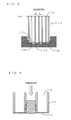
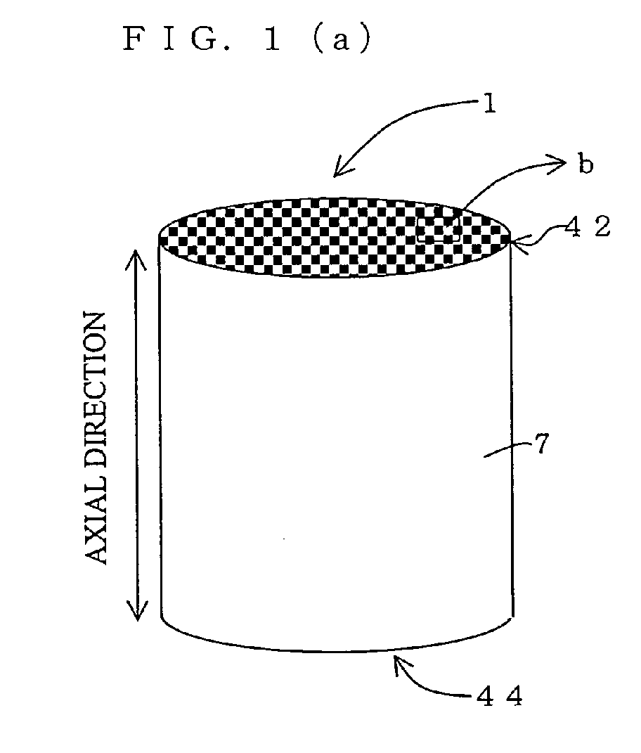
- a binder, a dispersion medium (D) or the like is preferably added to a firing material containing a solid particle (B) capable of unitarily joined with the solid particle (A) contained in the aforementioned forming raw material to prepare slurry, which is then put in a container 16 as shown in Fig. 5. Then, a honeycomb formed body 10 whose cells except for the cells to be plugged by the plugging material were masked with a masking member 12 at an end face 42 is immersed in the plugging material 6 to fill the plugging material in the end portions of the predetermined cells.
- the solid particle (B) is preferably selected from the examples of the solid particle (A) and more preferably the same kinds as the solid particle (A).
- the plugging material may contain another solid particle besides the solid particle (B). Another solid particle is preferably selected from the above examples of the solid particle (A).
- the pressure applied is preferably 0.1 to 10 kg/cm 2 G.
- the forming raw material in the forming step preferably contains a binder
- the plugging material preferably contains a binder capable of compatible with the binder contained in the forming raw material and more preferably contains the same binder.
- the plugging material and the forming raw material contain such a binder, the plugging material can easily be permeate in partition wall-formed body surrounding the plugged portions, and thereby unitary joining of the plugged portions and the partition walls surrounding the plugged portions in the following firing step is made easier.
- a binder contained in the plugging material and the forming raw material may be selected from the aforementioned examples of a binder.
- the forming raw material contains a binder
- an end face of a honeycomb formed body is heated at 200°C or more, preferably 300°C or more after the forming step to remove at least a part of the binder present in the vicinity of the end face, followed by the plugging step at the end face.
- the plugging material is slurry containing a dispersion medium (D) compatible with the dispersion medium (C). Also because of this, the plugging material can easily be permeate in the partition wall-formed body in the periphery thereof, and thereby making unitary forming of the plugged portions and the partition walls surrounding the plugged portions easier in the following firing step.
- the dispersion medium (C) and the dispersion medium (D) are water or hydrophilic mediums or that the dispersion medium (C) and the dispersion medium (D) are hydrophobic mediums such as oil and wax. It is further preferable that the dispersion medium (C) and the dispersion medium (D) are the same medium.
- the dispersion medium (C) is water
- almost all the dispersion medium (C) is removed by drying in some cases.
- the dispersion medium (C) is made to be contained again in the partition wall-formed body in the vicinity of the end face, that is, in the portion, in contact with the plugging material upon filling the plugging material, of the partition wall-formed body by means of spraying or the like, and the plugging step is conducted using a plugging material containing a dispersion medium (D) compatible with the dispersion medium (C) or a dispersion medium (D) which is the same as the dispersion medium (C).
- the presence of the mutually compatible dispersion mediums in the plugging material and the partition wall-formed body in the periphery thereof to some extent makes easier the permeation and mixing of components contained in the plugging material and the partition wall-formed body, and this makes unitary forming of the plugged portions and the partition walls surrounding the plugged portions easier in the following firing step.
- the plugging step is preferably conducted by heating the partition wall-formed body in the vicinity of the end face, that is, the portion, in contact with the plugging material upon filling the plugging material, of the partition wall-formed body to a predetermined temperature or higher.
- a predetermined temperature or higher is 100 to 300°C, and the plugging step is preferably conducted within this temperature range.
- the firing temperature can be conducted by raising temperature of the plugged honeycomb formed body formed in the above step in a predetermined firing atmosphere up to the temperature where the solid particles used are sintered or reacted and maintaining the temperature for a predetermined time.
- Firing temperature and atmosphere may suitably be changed depending on solid particles used, and those skilled in the art can select the firing temperature and atmosphere optimum for the solid particles used.
- firing can be conducted at the highest temperature of 1400 to 1450°C in the ambient atmosphere after degreasing in the ambient atmosphere; and in the case of using a silicon carbide powder and a metallic silicon powder as a raw material, firing can be conducted at the temperature of about 1550°C in an Ar atmosphere after degreasing in a N 2 atmosphere.
- a single furnace or a continuous furnace such as a tunnel furnace is generally used, and degreasing and firing can be conducted simultaneously here.
- a temperature rising speed and a cooling speed are not necessarily essential problems in the present invention, it is necessary to optimize a temperature rising speed and a cooling speed to uniformalize a temperature distribution inside a product depending the size of a product to be fired to realize uniform firing contraction and cooling contraction, and a temperature rising speed and a cooling speed are very important factors in production.
- a foaming resin as a pore former.
- a binder, a dispersant, and water are added to the mixture, and the mixture is kneaded to obtain clay.
- Any pore former may be used as long as it scatters and disappears in the firing step.
- an inorganic substance such as carbon based substance, a high-molecular weight compound such as plastic material, or an organic substance such as starch may be used alone or in combination.
- a honeycomb formed body is formed by extrusion forming and dried.
- a raw material powder containing the aforementioned main raw material and additives added as necessary about 10 to 40 parts by mass of water is added, and the mixture is kneaded to obtain a mixture having plasticity.
- the mixture having plasticity is kneaded with a vacuum kneader to give a raw material for forming.
- a honeycomb formed body can be obtained by extrusion forming with a ram-type extruder. Though the thus obtained honeycomb formed body can be dried in various methods, a combination of microwave drying and hot-air drying or a combination of dielectric drying and hot-air drying is preferable. There may alternatively be employed a special method such as freeze drying, reduced-pressure drying, vacuum drying, and far-infrared radiation drying.
- the dried honeycomb formed body is cut at both end faces to have a predetermined length.
- a film is disposed on an end face in a masking sub-step.
- a polyester film No. 631S#25 with film thickness of 50 ⁇ m, produced by Teraoka Seisakusho, Co., Ltd.
- An adhesive is applied on one surface of the film, and the film is applied on an end face of the honeycomb structure.
- holes are formed in a checkerwise pattern at the opening portions of the cells at an end face where the polyester film is applied on the honeycomb structure with a laser apparatus capable of NC scanning. When the hole is formed, the periphery of the holes is swollen because the film melts.
- the main raw material of the plugging material 0 to 20% by mass of kaolin having an average particle diameter of 1 to 20 ⁇ m, 37 to 40% by mass of talc having an average particle diameter of 5 to 60 ⁇ m, 15 to 45% by mass of aluminum hydroxide having an average particle diameter of 0.5 to 20 ⁇ m, 0 to 15% by mass of aluminum oxide having an average particle diameter of 1 to 20 ⁇ m, and 10 to 20% by mass of fused silica or quartz having a particle diameter of 1 to 200 ⁇ m as a cordierite ceramic raw material excellent in thermal resistance and low thermal expansibility from the view point of small difference in thermal expansion coefficient with the honeycomb formed body after firing.
- the main raw material of the plugging material preferably has a similar particle size distribution as the above honeycomb formed body from the viewpoint of small difference in firing shrinkage from the honeycomb formed body.
- the main raw material of the plugging material preferably has a similar composition as the raw material of the above honeycomb formed body from the viewpoint of bringing the thermal expansion coefficient ratio of a honeycomb fired body and a plugged material fired body close to 1.
- a filling sub-step is described.
- a cordierite-forming material To a cordierite-forming material are added water, a binder, a dispersant, and the like, to obtain slurry having a viscosity of about 200dPa ⁇ s.
- the slurry is put in a container for plugging.
- a honeycomb structure with a film having holes in a checkerwise pattern being applied is put in the container under a pressure to impregnate the honeycomb structure with the slurry from holes. After the completion of the impregnation, the honeycomb structure is taken out of the container. Thus, plugged portions for plugging cells are formed at an end face of the honeycomb structure.
- a suitable method for filling the plugging material up to the same face as the end face of the honeycomb structure is, for example, a method in which the plugging material is filled one in the first place, after a tip of the plugging material is moved in the inner direction of the cell passages, the plugging material filled is dried to be solidified adequately, and further the plugging material is filled into the cells. This is based on the finding that, though the tip of the plugging material sometimes moves in the inner direction of the cell passages by the first filling, the tip of the plugging material hardly moves even if the additional plugging material is filled into the cells.
- a phenomenon that the plugging material moves in the inner direction of the cell passages is due to volume shrinkage of the plugging material with water in the plugging material being absorbed by the partition wall portions of the honeycomb structure. Therefore, the tip of the plugging material moves in the inner direction of the cell passages, and the tip is depressed in comparison with the end face.
- the inventors call this phenomenon surface sink.
- the volume shrinkage of the plugging material is large, not only the tip of the plugging material on the end face side of the honeycomb structure, but also the tip end of the inner side of the cell passages is sometimes depressed.
- the plugging material can be filled up to the upper surface of the film or higher. However, the plugging material may be filled three times or more.
- the plugging material can be filled up to almost the same surface as the end face of the honeycomb structure, there are a case that the plugging material slightly protrudes and a case that the plugging material slightly depresses from the end face of the honeycomb structure by the filling of the plugging material. It may be left as it is, or when it protrudes, the protruding portion may be removed to give almost the same surface as the end face.
- the tip of the plugging material depresses too much, it is preferable to fill the plugging material again to make the depression smaller because soot in exhaust gas is prone to deposit in the depression. In a plurality of the above filling operations, it sometimes happens that air is drawn in the plugging material to form a void inside the plugging material.
- a void inside the plugging material is also formed by an air bubble which is mixed in the plugging material from the beginning. Therefore, it is also preferable to subject the plugging material to a degassing treatment.
- the size of the void is varied because it depends on the volume of drawn air and the size of a bubble in the plugging portion, it sometimes reaches about the size of a cell opening as an easily visible void. Even in such a case, since the plugged portions and the partition walls are unitarily joined, the function of the plugged portions can sufficiently be guaranteed.
- the honeycomb structure In the case that the honeycomb structure is unfired, it is necessary to determine an adequate volume of water because the partition walls is softening and deformed if superfluous water is added. There is an effect in suppressing the movement of the tip of the plugging material in a direction of cells by adding a suitable amount of fiber material of alumina fibers or mullite fibers or a thickener to the plugging material. Addition of a superfluous amount increases viscosity of the plugging material excessively to make difficult the filling of the plugging material in cell passages. Therefore, it is necessary to determine an adequate amount of addition.
- the plugged end face of the honeycomb structure is subjected to hot air having a temperature of 160°C for about five minutes without peeling the film. Drying can be performed with a hot plate. The same is conducted also for the other end face to form the plugging portions at both the end faces. Then, the honeycomb structure is fired to obtain a cordierite based plugged honeycomb structure.
- Partition walls of the cordierite based plugged honeycomb structure obtained practically based on the above method had a porosity of 67%, which was measured with a mercury porosimeter, and an average pore diameter of 27 ⁇ m.
- Each cell had a rectangular shape, partition walls had a thickness of about 0.3 mm, and the cell pitch was about 1.6 mm.
- the filter had a diameter of about 191 m and a length of about 200 mm.
- the plugged portions had a length of about 0.3 mm from an end face of the filter toward the inner direction of cell passages.
- a desired additive may be added to the ceramic material as necessary. Examples of the additive include the binders, dispersants, and pore forming materials which were specifically described above.
- the plugged honeycomb structure thus produced on the basis of the present invention as a DPF, was held under pressure by a ceramic mat (Commercial name: Interam Mat, produced by 3M) in a metallic case. Then, both end faces of the DPF was fixed with a fixing member, the fixing member was welded to the metallic case, and a cone was connected to the metallic case to produce a converter assembly.
- a converter assembly employing a conventional plugged honeycomb structured DPF was also produced. Then, each of the converter assemblies produced was connected to an exhaust gas system of a practical diesel engine (with a displacement of about 5 liters), and exhaust gas was sent to conduct a heating-cooling test. Each of the converter assemblies was decomposed and investigated. A trace of leakage of black smoke was recognized in an interface portion between a plugged portion of an end face of the DPF and a partition wall in the converter assembly of the conventional structure, while it was not recognized in the converter assembly of the present invention.
- Fig. 7 shows a photograph of a parallel section of a plugged honeycomb structured DPF (Example) produced by the method of the above present invention
- Fig. 8 shows a photograph of a parallel section of a plugged honeycomb structured DPF (Comparative Example) produced by the conventional method.
- the plugged portion and the partition wall surrounding the plugged portion are unitarily formed in the plugged honeycomb structures DPF of Example since there is no interface line observed between the plugged portion and the partition wall and a phase extending over both the plugged portion and the partition wall is observed, while it is understand that the plugged portion and the partition wall surrounding the plugged portion are not unitarily formed in the plugged honeycomb structures DPF of Comparative Example since there is an interface line observed between the plugged portion and the partition wall.
- the plugged honeycomb structured DPF obtained in Comparative Example was produced in the same manner as in Example except for the plugging step.
- Comparative Example refers to a method described in JP-A-57-42316, and a honeycomb structure having a diameter of 144 mm, a length of 150 mm, and a partition wall thickness of about 0.4, and a cell pitch of about 2.5 was formed and dried in completely the same manner as in Example and then fired without being plugged.
- a honeycomb structure fired body
- a plugging material slurry produced in completely the same manner as in Example and fired again to fire the plugging material.
- the honeycomb structure was already a fired body, large shrinkage was not caused in partition walls during the second firing, and large difference is generated in shrinkage between the partition walls and the plugged portion.
- the honeycomb structure has high strength and thermal shock resistance between the partition wall and the plugged portion and useful for various usage as a filter or the like of a DPF, etc.
- a production method of the present invention a plugged honeycomb structure having unitarily formed plugged portions and partition walls surrounding the plugged portions can easily be produced.
Landscapes
- Physics & Mathematics (AREA)
- Geometry (AREA)
- Chemical & Material Sciences (AREA)
- Chemical Kinetics & Catalysis (AREA)
- Engineering & Computer Science (AREA)
- Mechanical Engineering (AREA)
- Combustion & Propulsion (AREA)
- Thermal Sciences (AREA)
- General Engineering & Computer Science (AREA)
- Structural Engineering (AREA)
- Ceramic Engineering (AREA)
- Filtering Materials (AREA)
- Devices For Post-Treatments, Processing, Supply, Discharge, And Other Processes (AREA)
- Filtering Of Dispersed Particles In Gases (AREA)
Abstract
Description
a difference between rate of dimensional change (%) upon forming the plugged portions out of the plugging material and rate of dimensional change (%) upon forming the partition walls out of the partition wall-forming material is controlled to be 7% or less within the temperature range of the firing in the firing step.
It is considered that a phenomenon that the plugging material moves in the inner direction of the cell passages is due to volume shrinkage of the plugging material with water in the plugging material being absorbed by the partition wall portions of the honeycomb structure. Therefore, the tip of the plugging material moves in the inner direction of the cell passages, and the tip is depressed in comparison with the end face. The inventors call this phenomenon surface sink. When the volume shrinkage of the plugging material is large, not only the tip of the plugging material on the end face side of the honeycomb structure, but also the tip end of the inner side of the cell passages is sometimes depressed. Generally, by filling twice, the plugging material can be filled up to the upper surface of the film or higher. However, the plugging material may be filled three times or more.
Claims (11)
- A plugged honeycomb structure comprising:wherein said plugged portions and said partition walls surrounding said plugged portions are unitarily formed.partition walls disposed so as to form a plurality of cells extending from one end face to the other end face in an axial direction, andplugged portions disposed so as to plug the cells at one of the end faces,
- A plugged honeycomb structure according to Claim 1, wherein a length of said plugged portions in a longitudinal direction of the cells is ten times as long as a cell pitch or less.
- A plugged honeycomb structure according to Claim 1 or 2, wherein the length of said plugged portions in the longitudinal direction of the cells is two times as long as a thickness of said partition walls or more.
- A method for producing a plugged honeycomb structure, comprising:wherein the solid particle (A) and the solid particle (B) can unitarily be formed mutually in the firing step, anda forming step of forming a forming raw material containing a solid particle (A) into a honeycomb formed body provided with a partition wall-formed body disposed so as to form a plurality of cells extending from one end face to the other end face in an axial direction,a plugging step of filling a plugging material containing a solid particle (B) into end portions of cells of the honeycomb formed body to form a plugged honeycomb formed body, anda firing step of firing the plugged honeycomb formed body to form a plugged honeycomb structure provided with partition walls formed out of the partition wall-formed body and plugged portions formed out of the plugging material;
a difference between rate of dimensional change (%) upon forming the plugged portions out of the plugging material and rate of dimensional change (%) upon forming the partition walls out of the partition wall-forming material is controlled to be 7% or less within the temperature range of the firing in the firing step. - A method for producing a plugged honeycomb structure according to Claim 4, wherein the method further comprises a cooling step of cooling the plugged honeycomb structure, and a ratio of thermal expansion coefficient of the plugged portions to thermal expansion coefficient of the partition walls is made to be 0.3 to 3.0 in the temperature range of the cooling in the cooling step.
- A method for producing a plugged honeycomb structure according to Claim 4 or 5, wherein said plugging step includes a step of filling the plugging material from one end face of the honeycomb structure with pressurizing inside the cells from the other end face.
- A method for producing a plugged honeycomb structure according to any one of Claims 4 to 6, wherein the forming raw material contains a binder, and the plugging material contains a binder compatible with the binder contained in the forming raw material.
- A method for producing a plugged honeycomb structure according to any one of Claims 4 to 7, wherein the forming raw material contains a binder, and after the forming step, an end face of the honeycomb formed body is heated at 200°C or more to remove at least a part of the binder, followed by conducting the plugging step at the end face.
- A method for producing a plugged honeycomb structure according to any one of Claims 4 to 8, wherein the forming raw material is a slurry containing a dispersion medium (C), and the plugging material is a slurry containing a dispersion medium (D) compatible with the dispersion medium (C).
- A method for producing a plugged honeycomb structure according to Claim 9, wherein the honeycomb formed body is dried, subsequently, the partition wall-formed body is impregnated with the dispersion medium (C) in the vicinity of an end face, followed by conducting the plugging step at the end face.
- A method for producing a plugged honeycomb structure according to Claim 9, wherein the dispersion medium (C) and the dispersion medium (D) are hydrophobic, and the plugging step is conducted under the condition that temperature of the partition wall-formed body is higher than the normal temperature in the vicinity of an end portion.
Applications Claiming Priority (3)
| Application Number | Priority Date | Filing Date | Title |
|---|---|---|---|
| JP2003083213 | 2003-03-25 | ||
| JP2003083213 | 2003-03-25 | ||
| PCT/JP2004/003736 WO2004085029A1 (en) | 2003-03-25 | 2004-03-19 | Sealed honeycomb structure and method of producing the same |
Publications (3)
| Publication Number | Publication Date |
|---|---|
| EP1607130A1 true EP1607130A1 (en) | 2005-12-21 |
| EP1607130A4 EP1607130A4 (en) | 2006-08-02 |
| EP1607130B1 EP1607130B1 (en) | 2013-11-27 |
Family
ID=33094946
Family Applications (1)
| Application Number | Title | Priority Date | Filing Date |
|---|---|---|---|
| EP04722011.6A Expired - Lifetime EP1607130B1 (en) | 2003-03-25 | 2004-03-19 | Sealed honeycomb structure and method of producing the same |
Country Status (5)
| Country | Link |
|---|---|
| US (1) | US7556664B2 (en) |
| EP (1) | EP1607130B1 (en) |
| JP (1) | JP5005917B2 (en) |
| CN (1) | CN1795037B (en) |
| WO (1) | WO2004085029A1 (en) |
Families Citing this family (29)
| Publication number | Priority date | Publication date | Assignee | Title |
|---|---|---|---|---|
| JP2006046200A (en) * | 2004-08-05 | 2006-02-16 | Hitachi Ltd | Exhaust gas purification filter for diesel internal combustion engine, method for producing the same, and exhaust gas purification device |
| JP2006298745A (en) * | 2005-03-24 | 2006-11-02 | Ngk Insulators Ltd | Method for manufacturing honeycomb structure and honeycomb structure |
| FR2889184B1 (en) * | 2005-07-29 | 2007-10-19 | Saint Gobain Ct Recherches | PROCESS FOR THE PREPARATION OF A POROUS STRUCTURE USING POROGENIC SILICA AGENTS |
| KR100831836B1 (en) * | 2005-10-12 | 2008-05-28 | 이비덴 가부시키가이샤 | Honeycomb unit and honeycomb structured body |
| JP2007117817A (en) * | 2005-10-26 | 2007-05-17 | Hitachi Metals Ltd | Mesh sealing material of ceramic honeycomb filter and mesh sealing method |
| DE102005062192A1 (en) * | 2005-12-23 | 2007-07-05 | Ivoclar Vivadent Ag | supporting paste |
| JP4975331B2 (en) * | 2006-02-02 | 2012-07-11 | 日本碍子株式会社 | Method for manufacturing plugged honeycomb structure and plugged honeycomb structure |
| JP2007275869A (en) * | 2006-03-17 | 2007-10-25 | Ngk Insulators Ltd | Method for manufacturing cell structure |
| JP2007283755A (en) * | 2006-03-23 | 2007-11-01 | Ngk Insulators Ltd | Manufacturing method for sealed honeycomb structure, and sealed honeycomb structure |
| JP2008132751A (en) * | 2006-04-19 | 2008-06-12 | Ibiden Co Ltd | Manufacturing method of honeycomb structure |
| WO2007122707A1 (en) | 2006-04-19 | 2007-11-01 | Ibiden Co., Ltd. | Process for producing honeycomb structure |
| JP5082342B2 (en) * | 2006-08-31 | 2012-11-28 | 株式会社デンソー | Exhaust gas purification filter and manufacturing method thereof |
| WO2008038392A1 (en) * | 2006-09-28 | 2008-04-03 | Hitachi Metals, Ltd. | Process for producing ceramic honeycomb filter |
| CN101568415A (en) * | 2006-12-27 | 2009-10-28 | 日本碍子株式会社 | Process for producing plugged honeycomb structure |
| US7919033B2 (en) | 2007-07-18 | 2011-04-05 | Ngk Insulators, Ltd. | Method of manufacturing honeycomb structure and manufacturing apparatus thereof |
| US7722791B2 (en) | 2007-07-18 | 2010-05-25 | Ngk Insulators, Ltd. | Method for manufacturing honeycomb structure and manufacturing apparatus thereof |
| EP2231552A2 (en) * | 2007-11-05 | 2010-09-29 | Corning Incorporated | Low expansion cement compositions for ceramic monoliths |
| US20100052197A1 (en) * | 2008-08-27 | 2010-03-04 | Thomas James Deneka | Method for Manufacturing Ceramic Honeycombs |
| JP4825256B2 (en) * | 2008-10-31 | 2011-11-30 | 日本碍子株式会社 | Slurry discharge apparatus and slurry discharge method |
| FR2957529B1 (en) * | 2010-03-19 | 2012-04-06 | Saint Gobain Ct Recherches | FILTER STRUCTURE COMPRISING IMPROVED BLEACH MATERIAL |
| JP2012045541A (en) * | 2010-07-28 | 2012-03-08 | Sumitomo Chemical Co Ltd | Honeycomb structural body |
| US9205362B2 (en) | 2011-10-31 | 2015-12-08 | Corning Incorporated | Methods for manufacturing particulate filters |
| JP5875997B2 (en) * | 2012-03-22 | 2016-03-02 | 日本碍子株式会社 | Honeycomb structure and method for manufacturing honeycomb structure |
| CN102787884A (en) * | 2012-07-03 | 2012-11-21 | 宜兴王子制陶有限公司 | Hole sealing method of soot filter |
| US9255036B2 (en) | 2013-03-15 | 2016-02-09 | Corning Incorporated | Cellular ceramic article and method for manufacturing the same |
| JP5883410B2 (en) | 2013-03-29 | 2016-03-15 | 日本碍子株式会社 | Manufacturing method of honeycomb structure |
| CN108325386A (en) * | 2017-01-20 | 2018-07-27 | 中国石化仪征化纤有限责任公司 | A kind of half dead-end filter |
| JP6615802B2 (en) * | 2017-02-06 | 2019-12-04 | 日本碍子株式会社 | Method for manufacturing plugged honeycomb structure |
| CN109796221A (en) * | 2019-01-11 | 2019-05-24 | 宜兴王子制陶有限公司 | A kind of gasoline engine tail gas particle catcher |
Family Cites Families (14)
| Publication number | Priority date | Publication date | Assignee | Title |
|---|---|---|---|---|
| JPS577215A (en) * | 1980-06-16 | 1982-01-14 | Ngk Insulators Ltd | Preparation of ceramic honeycomb filter |
| JPS5742316A (en) | 1980-08-28 | 1982-03-09 | Ngk Insulators Ltd | Ceramic honeycomb filter |
| JPS5954682A (en) | 1982-09-20 | 1984-03-29 | 日本碍子株式会社 | Open end sealing method for ceramic honeycomb structure |
| JPH01297114A (en) | 1988-05-24 | 1989-11-30 | Ibiden Co Ltd | Mesh sealing material for honeycomb filter |
| JP3065746B2 (en) | 1991-11-12 | 2000-07-17 | イビデン株式会社 | Honeycomb filter sealing method |
| JP3461610B2 (en) * | 1995-03-08 | 2003-10-27 | 電気化学工業株式会社 | Sealing material, ceramic honeycomb structure using the same, and method of manufacturing the same |
| JPH1057730A (en) * | 1996-08-26 | 1998-03-03 | Matsushita Electric Ind Co Ltd | Ceramic honeycomb filter and method for manufacturing the same |
| JP3756721B2 (en) | 2000-03-24 | 2006-03-15 | 日本碍子株式会社 | Exhaust gas purification filter |
| JP3715174B2 (en) * | 2000-04-18 | 2005-11-09 | 日本碍子株式会社 | Manufacturing method of ceramic body |
| JP4222588B2 (en) | 2000-11-24 | 2009-02-12 | 日本碍子株式会社 | Honeycomb filter and manufacturing method thereof |
| JP2002173381A (en) | 2000-12-01 | 2002-06-21 | Denso Corp | Plugging method for ceramic honeycomb formed body |
| EP2206693A1 (en) * | 2001-04-23 | 2010-07-14 | Dow Global Technologies Inc. | Wall-flow monolith filter |
| JP4735917B2 (en) * | 2001-05-15 | 2011-07-27 | 日立金属株式会社 | Ceramic honeycomb filter |
| US7090714B2 (en) * | 2002-06-17 | 2006-08-15 | Hitachi Metals, Ltd. | Ceramic honeycomb filter |
-
2004
- 2004-03-19 CN CN2004800143692A patent/CN1795037B/en not_active Expired - Lifetime
- 2004-03-19 JP JP2005504023A patent/JP5005917B2/en not_active Expired - Lifetime
- 2004-03-19 WO PCT/JP2004/003736 patent/WO2004085029A1/en not_active Ceased
- 2004-03-19 US US10/548,813 patent/US7556664B2/en not_active Expired - Lifetime
- 2004-03-19 EP EP04722011.6A patent/EP1607130B1/en not_active Expired - Lifetime
Also Published As
| Publication number | Publication date |
|---|---|
| JPWO2004085029A1 (en) | 2006-06-29 |
| JP5005917B2 (en) | 2012-08-22 |
| WO2004085029A1 (en) | 2004-10-07 |
| EP1607130A4 (en) | 2006-08-02 |
| US7556664B2 (en) | 2009-07-07 |
| EP1607130B1 (en) | 2013-11-27 |
| US20060150598A1 (en) | 2006-07-13 |
| CN1795037A (en) | 2006-06-28 |
| CN1795037B (en) | 2010-12-22 |
Similar Documents
| Publication | Publication Date | Title |
|---|---|---|
| US7556664B2 (en) | Sealed honeycomb structure and method of producing the same | |
| KR101108902B1 (en) | Honeycomb filter | |
| EP2006010B1 (en) | Honeycomb structured body and method for manufacturing honeycomb structured body | |
| JP4266103B2 (en) | Method for producing porous ceramic body | |
| EP1780187B1 (en) | Honeycomb structure | |
| CN101421016B (en) | Honeycomb structure and method for manufacturing honeycomb structure | |
| EP2090351B1 (en) | Honeycomb structured body, exhaust-gas-purifying apparatus and method for manufacturing honeycomb structured body | |
| WO2006068256A1 (en) | Method for manufacturing honeycomb filter and honeycomb filter | |
| JP2009050849A (en) | Honeycomb filter for exhaust gas purification | |
| JP2003269132A (en) | Exhaust gas purification filter | |
| JP4001800B2 (en) | Method for manufacturing honeycomb catalyst carrier | |
| KR20070080588A (en) | Plugged honeycomb structure | |
| EP1604726A1 (en) | Honeycomb filter and method of manufacturing the same | |
| JP5523871B2 (en) | Manufacturing method of honeycomb filter | |
| JP3935159B2 (en) | Ceramic honeycomb filter | |
| EP2098348A1 (en) | Process for producing plugged honeycomb structure | |
| JP2009255045A (en) | Honeycomb filter | |
| JP4975570B2 (en) | Method for manufacturing honeycomb structure and honeycomb structure | |
| KR100841509B1 (en) | Honeycomb structure | |
| KR20080058970A (en) | Adhesive tape for sintering bonding containing inorganic component and organic component and manufacturing method of honeycomb ceramic filter using same | |
| KR101439510B1 (en) | Multilayer bonding structure of honeycomb ceramic filter |
Legal Events
| Date | Code | Title | Description |
|---|---|---|---|
| PUAI | Public reference made under article 153(3) epc to a published international application that has entered the european phase |
Free format text: ORIGINAL CODE: 0009012 |
|
| 17P | Request for examination filed |
Effective date: 20050926 |
|
| AK | Designated contracting states |
Kind code of ref document: A1 Designated state(s): AT BE BG CH CY CZ DE DK EE ES FI FR GB GR HU IE IT LI LU MC NL PL PT RO SE SI SK TR |
|
| AX | Request for extension of the european patent |
Extension state: AL LT LV MK |
|
| DAX | Request for extension of the european patent (deleted) | ||
| RBV | Designated contracting states (corrected) |
Designated state(s): DE FR |
|
| A4 | Supplementary search report drawn up and despatched |
Effective date: 20060630 |
|
| 17Q | First examination report despatched |
Effective date: 20070115 |
|
| GRAP | Despatch of communication of intention to grant a patent |
Free format text: ORIGINAL CODE: EPIDOSNIGR1 |
|
| INTG | Intention to grant announced |
Effective date: 20130717 |
|
| GRAS | Grant fee paid |
Free format text: ORIGINAL CODE: EPIDOSNIGR3 |
|
| GRAA | (expected) grant |
Free format text: ORIGINAL CODE: 0009210 |
|
| AK | Designated contracting states |
Kind code of ref document: B1 Designated state(s): DE FR |
|
| REG | Reference to a national code |
Ref country code: DE Ref legal event code: R096 Ref document number: 602004043889 Country of ref document: DE Effective date: 20140123 |
|
| REG | Reference to a national code |
Ref country code: DE Ref legal event code: R097 Ref document number: 602004043889 Country of ref document: DE |
|
| PLBE | No opposition filed within time limit |
Free format text: ORIGINAL CODE: 0009261 |
|
| STAA | Information on the status of an ep patent application or granted ep patent |
Free format text: STATUS: NO OPPOSITION FILED WITHIN TIME LIMIT |
|
| 26N | No opposition filed |
Effective date: 20140828 |
|
| REG | Reference to a national code |
Ref country code: DE Ref legal event code: R097 Ref document number: 602004043889 Country of ref document: DE Effective date: 20140828 |
|
| REG | Reference to a national code |
Ref country code: FR Ref legal event code: ST Effective date: 20141128 |
|
| PG25 | Lapsed in a contracting state [announced via postgrant information from national office to epo] |
Ref country code: FR Free format text: LAPSE BECAUSE OF NON-PAYMENT OF DUE FEES Effective date: 20140331 |
|
| PGFP | Annual fee paid to national office [announced via postgrant information from national office to epo] |
Ref country code: DE Payment date: 20230131 Year of fee payment: 20 |
|
| REG | Reference to a national code |
Ref country code: DE Ref legal event code: R071 Ref document number: 602004043889 Country of ref document: DE |