EP1606122B1 - Clipping assembly of a document file - Google Patents
Clipping assembly of a document file Download PDFInfo
- Publication number
- EP1606122B1 EP1606122B1 EP03816385A EP03816385A EP1606122B1 EP 1606122 B1 EP1606122 B1 EP 1606122B1 EP 03816385 A EP03816385 A EP 03816385A EP 03816385 A EP03816385 A EP 03816385A EP 1606122 B1 EP1606122 B1 EP 1606122B1
- Authority
- EP
- European Patent Office
- Prior art keywords
- base plate
- clipping
- central portion
- pivotable
- belonging
- Prior art date
- Legal status (The legal status is an assumption and is not a legal conclusion. Google has not performed a legal analysis and makes no representation as to the accuracy of the status listed.)
- Expired - Lifetime
Links
- 230000003014 reinforcing effect Effects 0.000 claims abstract description 39
- 238000011068 loading method Methods 0.000 claims abstract description 17
- 238000003825 pressing Methods 0.000 claims description 28
- 230000000284 resting effect Effects 0.000 claims description 9
- 238000005452 bending Methods 0.000 description 16
- 238000004519 manufacturing process Methods 0.000 description 13
- 239000000463 material Substances 0.000 description 11
- 230000000712 assembly Effects 0.000 description 8
- 238000000429 assembly Methods 0.000 description 8
- 229910000831 Steel Inorganic materials 0.000 description 5
- 239000010959 steel Substances 0.000 description 5
- 239000002184 metal Substances 0.000 description 4
- 238000005096 rolling process Methods 0.000 description 4
- 238000006243 chemical reaction Methods 0.000 description 2
- 238000000034 method Methods 0.000 description 2
- 210000002445 nipple Anatomy 0.000 description 2
- 238000003466 welding Methods 0.000 description 2
- 101100179591 Caenorhabditis elegans ins-22 gene Proteins 0.000 description 1
- 238000004873 anchoring Methods 0.000 description 1
- 230000015572 biosynthetic process Effects 0.000 description 1
- 230000000295 complement effect Effects 0.000 description 1
- 238000010276 construction Methods 0.000 description 1
- 230000007797 corrosion Effects 0.000 description 1
- 238000005260 corrosion Methods 0.000 description 1
- 238000013461 design Methods 0.000 description 1
- 230000000694 effects Effects 0.000 description 1
- 230000008030 elimination Effects 0.000 description 1
- 238000003379 elimination reaction Methods 0.000 description 1
- 238000011156 evaluation Methods 0.000 description 1
- 238000003780 insertion Methods 0.000 description 1
- 230000037431 insertion Effects 0.000 description 1
- 238000005461 lubrication Methods 0.000 description 1
- 238000012423 maintenance Methods 0.000 description 1
- 230000007935 neutral effect Effects 0.000 description 1
- 239000004033 plastic Substances 0.000 description 1
- 229920003023 plastic Polymers 0.000 description 1
- 238000003860 storage Methods 0.000 description 1
- 230000000153 supplemental effect Effects 0.000 description 1
Images


Classifications
-
- B—PERFORMING OPERATIONS; TRANSPORTING
- B42—BOOKBINDING; ALBUMS; FILES; SPECIAL PRINTED MATTER
- B42F—SHEETS TEMPORARILY ATTACHED TOGETHER; FILING APPLIANCES; FILE CARDS; INDEXING
- B42F13/00—Filing appliances with means for engaging perforations or slots
- B42F13/16—Filing appliances with means for engaging perforations or slots with claws or rings
- B42F13/20—Filing appliances with means for engaging perforations or slots with claws or rings pivotable about an axis or axes parallel to binding edges
- B42F13/22—Filing appliances with means for engaging perforations or slots with claws or rings pivotable about an axis or axes parallel to binding edges in two sections engaging each other when closed
- B42F13/24—Filing appliances with means for engaging perforations or slots with claws or rings pivotable about an axis or axes parallel to binding edges in two sections engaging each other when closed wherein one section is in the form of fixed rods
-
- B—PERFORMING OPERATIONS; TRANSPORTING
- B42—BOOKBINDING; ALBUMS; FILES; SPECIAL PRINTED MATTER
- B42F—SHEETS TEMPORARILY ATTACHED TOGETHER; FILING APPLIANCES; FILE CARDS; INDEXING
- B42F13/00—Filing appliances with means for engaging perforations or slots
- B42F13/16—Filing appliances with means for engaging perforations or slots with claws or rings
- B42F13/20—Filing appliances with means for engaging perforations or slots with claws or rings pivotable about an axis or axes parallel to binding edges
- B42F13/22—Filing appliances with means for engaging perforations or slots with claws or rings pivotable about an axis or axes parallel to binding edges in two sections engaging each other when closed
Definitions
- the invention belongs to requisites, which are adapted for sorting and organizing documents, especially of such kind, which comprise corresponding means for inserting through the openings, by which the stored documents are equipped, namely among two-part clipping assemblies consisting of a stable part provided with at least two stable pins and a pivotable part also provided with at least two pivotable pins.
- the invention is based on the problem, how to enhance stiffness or to reduce deformability of such a clipping assembly, especially of a base plete thereof, by means of which the said assembly is attached onto each belonging cover of a document file, which on the other hand also means, that by taking into account all requirements related to use of such products, especially the allowed deformability in any regular loading situation, the weight of such assembly should be essentially reduced with respect to the weight of the previously known assemblies, and moreover, manufacturing thereof should also be easier and would require less energy by forming thereof.
- document files are widely known. Usually, such products are similar to other folders, which are intended for storing sheets, which are previously perforated in order to comprise appropriate openings, arranged on a required distance therebetween.
- Such document file ordinary consists of two covers or boards, between which there is an intermediate board, and appropriate clipping assembly is attached onto a rearward board. Attaching is ordinary achieved by means of riveting.
- the covers ordinary consist of cardboard or other similar material on the basis of paper, which may be coated with a layer of plastics or provided with a surface treated in any other manner with respect to various requirements.
- the said clipping assembly mostly consists of metallic parts.
- the document file as such belongs to typical products, which are manufactured by the so-called serial mass production, and such manufacturing is ordinary exposed to extreme care with respect to reduction of manufacturing expenses, so that manufacturing is profitable exclusively under extremely reduced manufacturing costs.
- such product must fulfill various requirements. For example, withstanding against the moisture has to be ensured and also appropriate durability.
- the belonging clipping assembly must be resistant against the corrosion and also precisely manufactured, and especially, its stiffnes has to be sufficient to enable simple opening or closing without disturbances even in a completely loaded state thereof.
- a further discussion shall be focused more or less exclusively to problems related to ensuring a required stiffness of such assembly.
- the stiffness is sufficient, when by completely loaded document file deflections i.e. deformations of pivotable and stable pins are kept within determined limits, by which a desited co-axial abutment of the corresponding pins is still maintained, and when undesired opening of a file is excluded. Accordingly, by completely loaded document file, opening and closing thereof may still be performed without any disturbances, and undesired removing sheets is still impossible, although the document file is held by user by means of only a single board thereof and in its hanging state.
- the clipping assembly of a document file commonly consists of a stable part, which comprises a desired number of stable pins, as well as of a pivotable part, which includes a desired number of pivotable pins.
- Each of the said pivotable pins may be swiveled either in a direction towards the belonging stable pin or in the opposite direction, i.e. from the stable pin away.
- Each corresponding pair of a stable pin and a pivotable pin forms a U-shaped loop, which extends through appropriate openings, which have to be perforated on each paper sheet, intended for inserting into a file.
- various assemblies are available, which have various number of pivotable pins and stable pins, by which the said number may be two, three or even more.
- the said pins may be manufactured and arranged in accordance with e.g. German standards (DIN) related to archive requisites for documents, which are perforated by two openings, where a distance between these openings is 80 mm.
- DIIN German standards
- Such assembly is foreseen for attaching onto a rearward cover of a document file and consists of a stable base plate, on which two stable pins made of a relatively thick metal wire with a round cross-section are attached on the required distance therebetween, as well as of a pivotable base plate, on which two pivotable pins are fixed.
- Each of the said stable pins is set approximately perpendicularly with respect to the said rectangular plate and is curved in form of a letter J at appropriate distance from the said plate and in the direction towards the belonging movable pin.
- a movable plate is available, which may by one of the embodiment also be manufactured directly from a curved part of a stable base plate, while by the other embodiments the said plate is attached to the stable plate.
- the said movable base plate is equipped with two pins, which may be moved by moving the said plate. Analogously like the previously mentioned pins, also these pins are manufactured of a relatively thick wire having a circular cross-section and being curved towards the belonging stable pins.
- a cantilever is foreseen on the stable base plate, which is equipped with a swiveling point of an actuating lever.
- the said lever consists of two portions, where the longer portion is intended for actuation i.e. for closing or opening the clipping assembly, while the shorter portion rests on the surface of the pivotable base plate and serves for moving thereof.
- the pivotable base plate is displaced with respect to the stable plate, by which the pivotable pins are moved either towards the stable pins or in the opposite direction.
- the forming tools which are intended for bending thicker steel plates, are exposed to essential loadings, and are ordinary much more complicated and more expensive like the tools intended for bending essentially thinner steel plates, which is in addition to higher costs of material also expressed in total expenses related to manufacturing such assembly.
- each pin is equipped with a conical protrusion, by means of which it may be inserted into a conical seat, which is available in the base plate. Consequently, such enlargement of contact surfaces between the base plate and the corresponding pins may no doubt lead to improved anchoring and reduces deformability, so that the distance between the axes of the pins may be easier kept within the determined values.
- DE 43 27 270 Al a similar problem is described, which is however solved in a different manner. Unfortunately, none of these solutions may not essentially increase the stiffness of the clipping assembly, since the deviations of the distance between the axes of the pins mostly result from deformations of the base plate and not of the pins.
- a cutout is aranged in the central portion of the base plate, which is bent into a inclined position, almost perpendicularly with respect to the surface of the base plate, which serves for establishing a desired swiveling point intended for connecting appropriate lever, which serves for displacing the said pivotable part of the clipping assembly against the pressure of appropriate spring.
- the base plate is still easiliy deformable in its longitudinal direction, i.e. by bending thereof arround its neutral central axis extending in the middle of the plate in the transversal direction thereof at least essentially on the level of the plate itself.
- the present invention relates to a clipping assembly of a document file, which is especially intended for attaching to the interior surface of the rear cover of a document file and consists of a base plate, a clipping set and an actuating set.
- the base plate may also comprise, in addition to attaching openings, appropriate positioning means, which may be arranged adjacent to the central portion, in which an essentially inclined, with respect to the plane of the base plate almost perpendicularly directed cantilever is available, which is equipped with a swiveling point and a limitation means adapted for cooperation with the actuating set.
- a clipping set which is available on the said base plate and supported by appropriate spring, consists of at least two stable pins as well as of a pivotable part consisting of complementary pivotable pins.
- the stable pins are mounted in a non-detachable manner onto the base plate adjacent to the belonging longitudinal edge.
- the pivotable part is by means of its coaxially arranged guiding portions pivotably inserted within appropriate bearings, which are arranged adjacent to the other longitudinal edge of the base plate, and comprises at least two pivotable pins, which are adapted for cooperation with the said stable pins in sense of pressing each pivotable pin against each corresponding stable pin, as well as a linear central portion, which extends parallel with respect to the said guiding portions and is adapted for cooperation with the said actuating set, while between the said central portion and the said guiding portions appropriate inclined intermediate portions are available.
- the actuating set consists of a double-arm actuating lever, the longer arm of which serves for ensuring a force, which is required for moving the assembly from its opened to its closed position or vice-versa, while its shorter arm is pivotable connected to the cantilever in the area of the swiveling point and is moreover equipped with a pressing means intended for resting on the central portion of the clipping set in sense of pressing in opposite direction with regard to the force resulting from a spring, by means of which the said pivotable part is supported on the base plate and simultaneously pivotable inserted within the bearings.
- the said plate comprises at least one elevation, which is arranged in the area below each intermediate portion lying between the central portion and each belonging guiding portion and/or below each belonging guiding portion of the clipping set, and in addition, the central portion of the said base plate below the cantilever is elevated above the other areas of the base plate by means of a surrounding bow, which extends along at least a part of the circumference of the said portion.
- the said elevations below the intermediate portions of the pivotable part are preferably available in form of pressed protrusions, but may also be formed e.g.
- the base plate comprises one elevation arranged below each of both intermediate portions available between the central portion and each belonging guiding portion of the clipping set. It is moreover also possible to arrange elevations to the base plate below the guiding portions of the pivotable part.
- the base plate may furthermore comprise, in addition to the said elevations as well as to the elevated central portion, which is at least partially surrounded by the bow, at least one longitudinal reinforcing means and/or at least one transversal reinforcing means.
- the said longitudinal reinforcing means consists of a rib extending along the base plate, as well as of a groove extending parallel with respect to the said rib and adjacent trereto.
- Such longitudinal reinforcing means is preferrably arranged adjacent to the longitudinal edge and closely to the stable pins.
- the base plate may comprise at least one longitudinal reinforcing means, which consists of two separate grooves extending co-linearly at least approximately in the longitudinal direction of the base plate, namely at least essentially parallel with respect to at least one of the longitudinal edges of the base plate. This last mentioned reinforcing means may however be present, when the elevations are available below the intermediate portions of the pivotable part of the clipping set.
- the base plate comprises at least one transversal reinforcing means in form of a knicked groove, which extends among each corresponding stable pin and the belonging pivotable pin as well as the elevated central portion of the base plate, and is preferrably arranged adjacent to the positioning means in such a manner, that it surrounds at least partially the said positioning means.
- the preferred embodiment of such transversal reinforcing means is conceived in form of a knicked groove, which consists of a central portion extending at least approximately in the longitudinal direction of the base plate i.e.
- the preferred embodiment of the base plate comprises two transversal reinforcing means, each of them is arranged in a desired area, preferrably arround each belonging positioning means.
- the said elevations on the base plate which are preferrably arranged below the intermediate portions of the pivotable part of the clipping set, are with respect to their height adapted for resting the belonging intermediate portion available between the central portion and the belonging guiding portion onto the belonging one of said elevations during the maximal loading, which occurs by passing the pressing means of the actuating set over the lowest point i.e. the point of minimal distance thereof with respect to the base plate.
- the central portion of the base plate is equipped below the cantilever with appropriate swiveling point of the double-arm lever of the actuating set, and moreover, the base plate comprises a bow, thanks to which the said central portion is elevated with respect to other areas of the base plate.
- a clipping assembly of a document file which has been created in accordance with the present invention and is shown in the drawings, consists of a base plate 1, on which a clipping set 2 is arranged, which can be placed in each desired position by means of appropriate actuation set 3.
- the base plate 1 consists of an essentially uniform part of a cold-formed metal plate having slightly rounded corner areas 110', 110", 120', 120" and comprising appropriate positioning means 10', 10", which are by this particular embodiment available as round bores and serve exclusively for the purpose of positioning during performing required steps in the process of manufacturing the base plate 1 and/or completing the assembly, while on the other hand, the said means have no essential influence with regard to functioning of the assembly as such.
- the said bearings 122', 122" are in this particular embodiment established by means of cutting-off trapezoidal parts of the material of the base plate 1 and bending thereof during assembling in the direction towards the belonging longitudinal edge 121 of the base plate 1, so that at least approximately cyllindrical passage is formed inside of each bearing 122', 122".
- a cantilever 14 is arranged in the central area 16 of the base plate 1, which comprises a swiveling point 140 adapted for cooperation with the actuation set 3, which will be disclosed later. Also the said cantilever 14 is formed by means of cutting-off material of the base plate 1 and deflecting thereof from the level of the said base plate 1 into another position, which is shown in the enclosed drawing.
- the cantilever 14 is bent into an inclined position, and actually extends almost perpendicularly with respect to the surface of the base plate 1.
- the base plate 1 in this particular embidiment comprises four bores 41, 42, 43, 44, which serve for mounting the assembly to the belonging cover of a desired document file, which is however not shown in the drawing. Other features will be described during the further explanation.
- the clipping set 2 consists of a stable part 21 which is formed by stable pins 21', 21", as well as of a movable part 22, which is pivotable attached onto the base plate 1 and comprises pivotable pins 22', 22".
- Each of the said stable pins 21', 21" consists of a metal wire or rod having circular or at least essentially circular cross-section, and is in the area of the said seats 112', 112" fixed in a non-detachable manner onto the said base plate 1, extending thereby at least essentially perpendicularly with respect to the said base plate 1.
- utmost portions 210', 210" of the pins 21', 21" are slightly bended towards the belonging pins 22', 22" of the pivotable part 22 of the clipping set 2.
- the pivotable part 22 of the clipping set 2 also consists of a metal wire or rod having circular or at least essentially circular cross-section. It is important, that the said pivotable part 22 is adapted for pivotable attachment onto the base plate 1 as well as for appropriate cooperation with the actuation set 3, and especially also for coaxial alignment of pivotable pins 22', 22" with respect to the stable pins 21', 21" in the closed state of the assembly as shown in the Figs. 1 to 3 .
- the discussed pivotable part 22 comprises two coaxially extending, but in the axial direction separately arranged linear guiding portions 221', 221", which are adapted for insertion into corresponding bearings 122', 122" on the base plate 1, and furthermore also a linear central portion 222, and moreover also two pivotable pins 22', 22", which extend at least essentially perpendicularly with respect to the said base plate 1 and on the desired distance therefrom, and are slightly bent towards to the belonging stable pins 21', 21 ".
- Intermediate portions 223', 223 which are lying between the said central portion 22 and each belonging guiding portion 221', 221", extend inclined from each corresponding guiding portion 221', 221" to the central portion 222.
- the said guide portions 221', 221" of the pivotable part 22 of the clipping set 2 extend coaxially each to another and moreover also at least essentially parallel with respect to the adjacent longitudinal edge 121 of the base plate 1, and are moreover separately inserted into the belonging bearings 122', 122" as available on the base plate 1, by which the pivotable part 22 of the clipping set 2 may be swiveled with respect to the base plate 1 and also to the stable pins 21', 21" for a desired angle, which as a matter of fact enables opening or closing the assembly according to the invention, as evident in the Figs. 3 and 5 .
- the said central portion 222 is adapted for establishing cooperation between the pivotable part 22 and the actuating set 3.
- the central portion 222 extends at least essentially parallel and non-coaxially with respect to the said guiding portions 221', 221".
- Such embodiment may be achieved by means of trapezoidal bending of the material of the pivotable part 22 of the clipping set 2, which is visible in the enclosed drawing as well as in the documents belonging to the prior art.
- pivotable part 22 of the clipping set 2 is supported in the area of the central portion 222 by means of a spring 23, which is attached to the base plate 1 and intended for establishing a required pressure against the pivotable part 22 in the central portion 222 thereof, the consequence of which is a springy supported swiveling of the pivotable part 22 of the clipping set 2 on the base plate 1.
- the actuating set 3 of the assembly comprises a double-arm actuating lever 31, which consists of a longer arm 311 and a shorter arm 312 as well as of appropriate pressing means 313.
- the said longer arm 311 is intended for establishing a required force in a desired direction, which is required for opening or closing the assembly as such, namely for displacing the pivotable part 22 of the clipping set 2.
- the said lever 31 is pivotably attached to the said swiveling point 140 on the cantilever 14 on the base plate 1 by means of its longer arm 312, where the maximum declination of the arm 31 is determined by the position of a limitation means 141, which is foreseen on the cantilever 14 and formed as a protrusion or deflection on the surface of the cantilever 14 faced towards the lever 31.
- the said pressing means 313 is arranged at least essentially in the area of coinciding the said arms 311, 312 of the lever 31, and is in the discussed embodiment formed by a rolling element 3130, which is freely turnable placed on the belonging pivot 3131 1 arranged on the said lever 31.
- Figs. 4 and 5 the clipping assembly is shown in its opened state, into which any desired documents may be inserted, which must however be previously perforated in appropriate manner, namely depending on the distance between the pins 21', 21".
- the stable pins 21', 21" are fixed on the base plate 1, while the pivotable part 22 of the clipping set 2 is swiveled away due to the pressure of the spring 23, so that the pivotable pins 22', 22" are placed at a certain distance from the stable pins 21', 21".
- the lever 31 of the acuating set 3 is swiveled into its end position at the maximal distance from the base plate 1, and the rolling element 3130 of the pressing means 313 is rest onto the central portion 222 of the pivotable part 22 of the clipping set 2, while the lever 31 of the actuating set 3 is rest on the limitation means 141 of the cantilever 14 of the base plate 1, so that any further swiveling of the lever 31 due to the pressure of the spring 23 against the pivotable part 22 of the clipping set 2 is disabled.
- the loadings occuring on the pivotable part 22 of the clipping set 2 are schematically shown in the Fig. 6 .
- the pivotable part 22 is presented in its unloaded state by means of a thickened line, while the same part 22 is shown by means of a dotted line in its loaded and adequately deformed state.
- the said pivotable part 22 is loaded in its central part 222 by means of the force F, which is a consequence of resting the pressing means 313 of the actuating set 3 against the central portion of the pivotable part 22 of the clipping set 2 in that moment, when the said pressing means 313 is moved into its lower position, the closest to the base plate 1.
- the forces R1 and R2 are reaction forces, by which the pivotable part is loaded in the area of its portions 221', 221" as placed in the corresponding bearings 122', 122" on the base plate 1.
- the pivotable part 22 is exposed to bending stresses, and its ins 22', 22" in such a state show the tendency of moving one towards another. Deformations of such kind may result damages on documents, which are stored within the document file.
- the base plate 1 is exposed to bending stresses as a consequence of the force resulting from resting the pressing means 313 against the central portion 222 of the pivotable part 22 of the clipping set 2.
- This force is transferred via the swiveling point 140 onto the cantilever 14 acting thereby in the direction away from the base plate 1, so that the base plate 1 shows the tendency of bending, namely deflecting the central area 16 below the cantilever 14 in the direction from the ground away, as well as deflecting central portions of the longitudinal edges 111, 121 of the base plate I in the same direction.
- reinforcing elevations 15', 15" are arranged on the base plate 1 in the area of resting intermediate portions 223', 223", which are in this particular embodiment formed in a quite simple manner in form of pressed protrusions.
- the main purpose of improving the base plate 1 by means of these elevations 15', 15” is to ensure appropriate resting of intermediate portions 223', 223" of the pivotable part 22 of the clipping set 2 onto the said elevations 15', 15" each time, when the base plate 1 is exposed to maximum stresses by moving the pressing means 313 into the lowest position and abutting the pivotable pins 22', 22" towards the stable pins 21', 21". In such a way, deformations of the pivotable part 22 of the clipping set 2 and also of the base plate 1 as such are essentially reduced in this state when being exposed to maximal stresses.
- Figs. 6 and 7 show the situation related to loadings and deformation of the pivotable part 22 of the clipping set 2, when resting onto the said elevations 15', 15".
- reduced forces r1 and r2 occur in the area of bearings 122', 122" instead of the former reaction forces (R1 and R2 according to Fig. 6 ) in the opposite direction, and opposite with respect to them, in the area of the said elevations 15', 15" the other forces P1 and P2 are available, which are indeed some stronger, but are thanks to their direction in such situation essentially easier acceptable. Accordingly, deformation of the pins 22', 22" is essentially reduced.
- the described loading situation brings essential benefits also when bearing in mind the loadings and deformations occuring by the base plate I itself. Due to pressing the intermediate portions 223', 223" of the pivotable part 22 of the cliping set 2 towards the elevations 15', 15", bending of the base plate 1 in this area may be essentially reduced.
- the central portion 16 of the base plate 1 arround the cantilever 14 is equipped with an elevated surrounding bow 160, so that the said portion 16 is elevated and lies above the other areas of the base plate 1, and is in fact arranged as the top portion of the base plate 1.
- a further measure in course of essentially reduction or elimination deformations of the base plate 1 in sense of deflecting the longitudinal edges 111, 121 in the directions from the ground away, is realized by providing longitudinal reinforcing means 17, 18.
- the first longitudinal reinforcing means 17 is arranged adjacent to the longitudinal edge 11 lying on the same side of the base plate 1 as the stable pins 21', 21".
- the said reinforcing means 17 consists of a rib 171, extending at least essentially parallel with respect to the belonging edge 111 of the base plate, as well as of a groove 172 in its adjacency, which also extends in the longitudinal direction of the base plate 1.
- Still further longitudinal reinforcing means 18 is arranged on the opposite side of the base plate 1, consisting thereby of two separate colinearly directed grooves 181, 182, extending at least approximately in the longitudinal direction of the base plate 1, i.e. at least substantially parallel with respect to at least one of the longitudinal edges 111, 112 of the base plate 1.
- transversal reinforcing means 19', 19" are foreseen. These reinforcing means 19', 19” are arranged among each corresponding stable pin 21', 21" and pivotable pin 22', 22" as well as the central portion 16. In this particular embodiment, the transversal reinforcing means 19', 19" are arranged arround the positioning means 10', 10".
- Each of these reinforcing means 19', 19 is available in form of a curved or knicked groove, the central section 191', 191" of which extends in the longitudinal direction of the base plate 1, and coincides with the belonging end sections 192', 192" and 193', 193".
- the central section 191', 191" of the transversal reinforcing means 19', 19” is arranged on such side of the positioning means 10', 10", which is arranged closely to the stable pins 21', 21", while the end sections 192', 192" and 193', 193" extends on each side of the positioning means 10', 10" towards the bearings 122', 122" in a slightly inclined direction each towards another without coinciding each to another.
- the stiffness thereof is essentially improved with respect to the base plates of various clipping assemblies as known from the prior art.
- the said elevations 15', 15" are preferably available in form of pressed protrusions, but may also be formed e.g. by means of cutting-out and subsequently bending a part of the material of the base plate 1, or also as a nipple or any other protrusion, which may be attached to the base plate 1 in a relevant area thereof either by means of welding or riveting or in any other similar mathod of attaching.
- the belonging elevation 15', 15" is available below each of the said two intermediate portions 223', 223" of the pivotable part 22 of the clipping set 2 a single elevation 15', 15", it is also possible to arrange elevations below the guiding portions 221', 221" of the pivotable part 22 of the clipping set 2. In such case, the longitudinal reinforcing means 181, 182 needs not to be present on the base plate 1.
Landscapes
- Sheet Holders (AREA)
- Clamps And Clips (AREA)
- Portable Nailing Machines And Staplers (AREA)
- Document Processing Apparatus (AREA)
- Silver Salt Photography Or Processing Solution Therefor (AREA)
Abstract
Description
- In field of bookbinding and requisites intended for clipping and storage of documents, the invention belongs to requisites, which are adapted for sorting and organizing documents, especially of such kind, which comprise corresponding means for inserting through the openings, by which the stored documents are equipped, namely among two-part clipping assemblies consisting of a stable part provided with at least two stable pins and a pivotable part also provided with at least two pivotable pins.
- By this, the invention is based on the problem, how to enhance stiffness or to reduce deformability of such a clipping assembly, especially of a base plete thereof, by means of which the said assembly is attached onto each belonging cover of a document file, which on the other hand also means, that by taking into account all requirements related to use of such products, especially the allowed deformability in any regular loading situation, the weight of such assembly should be essentially reduced with respect to the weight of the previously known assemblies, and moreover, manufacturing thereof should also be easier and would require less energy by forming thereof.
- Various document files are widely known. Mostly, such products are similar to other folders, which are intended for storing sheets, which are previously perforated in order to comprise appropriate openings, arranged on a required distance therebetween. Such document file ordinary consists of two covers or boards, between which there is an intermediate board, and appropriate clipping assembly is attached onto a rearward board. Attaching is ordinary achieved by means of riveting. The covers ordinary consist of cardboard or other similar material on the basis of paper, which may be coated with a layer of plastics or provided with a surface treated in any other manner with respect to various requirements. The said clipping assembly mostly consists of metallic parts.
- The document file as such belongs to typical products, which are manufactured by the so-called serial mass production, and such manufacturing is ordinary exposed to extreme care with respect to reduction of manufacturing expenses, so that manufacturing is profitable exclusively under extremely reduced manufacturing costs. On the other hand, regardless to the said costs, such product must fulfill various requirements. For example, withstanding against the moisture has to be ensured and also appropriate durability. The belonging clipping assembly must be resistant against the corrosion and also precisely manufactured, and especially, its stiffnes has to be sufficient to enable simple opening or closing without disturbances even in a completely loaded state thereof. In order to clarify the idea of the proposed invention, a further discussion shall be focused more or less exclusively to problems related to ensuring a required stiffness of such assembly. In addition, it should be noted, that the stiffness is sufficient, when by completely loaded document file deflections i.e. deformations of pivotable and stable pins are kept within determined limits, by which a desited co-axial abutment of the corresponding pins is still maintained, and when undesired opening of a file is excluded. Accordingly, by completely loaded document file, opening and closing thereof may still be performed without any disturbances, and undesired removing sheets is still impossible, although the document file is held by user by means of only a single board thereof and in its hanging state.
- As already mentioned, the clipping assembly of a document file commonly consists of a stable part, which comprises a desired number of stable pins, as well as of a pivotable part, which includes a desired number of pivotable pins. Each of the said pivotable pins may be swiveled either in a direction towards the belonging stable pin or in the opposite direction, i.e. from the stable pin away. Each corresponding pair of a stable pin and a pivotable pin forms a U-shaped loop, which extends through appropriate openings, which have to be perforated on each paper sheet, intended for inserting into a file. Still further, it should be noted, that various assemblies are available, which have various number of pivotable pins and stable pins, by which the said number may be two, three or even more. However, for understanding the purpose of the invention it seems to be quite sufficient, if the further discussion shall be limited to the most simple solutions of such assemblies having two pivotable and two stable pins, however without any limitation with regard to the scope of the invention. The said pins may be manufactured and arranged in accordance with e.g. German standards (DIN) related to archive requisites for documents, which are perforated by two openings, where a distance between these openings is 80 mm.
- One of the earliest assemblies of such kind was described in
DE 816 689 . Such assembly is foreseen for attaching onto a rearward cover of a document file and consists of a stable base plate, on which two stable pins made of a relatively thick metal wire with a round cross-section are attached on the required distance therebetween, as well as of a pivotable base plate, on which two pivotable pins are fixed. Each of the said stable pins is set approximately perpendicularly with respect to the said rectangular plate and is curved in form of a letter J at appropriate distance from the said plate and in the direction towards the belonging movable pin..On the other hand, adjacent to one of the longer edges thereof, a movable plate is available, which may by one of the embodiment also be manufactured directly from a curved part of a stable base plate, while by the other embodiments the said plate is attached to the stable plate. The said movable base plate is equipped with two pins, which may be moved by moving the said plate. Analogously like the previously mentioned pins, also these pins are manufactured of a relatively thick wire having a circular cross-section and being curved towards the belonging stable pins. Still further, a cantilever is foreseen on the stable base plate, which is equipped with a swiveling point of an actuating lever. Bearing in mind the position of the said swiveling point, the said lever consists of two portions, where the longer portion is intended for actuation i.e. for closing or opening the clipping assembly, while the shorter portion rests on the surface of the pivotable base plate and serves for moving thereof. By swiveling the lever, the pivotable base plate is displaced with respect to the stable plate, by which the pivotable pins are moved either towards the stable pins or in the opposite direction. However, in such a manner it is extremely difficult to ensure, that intensity of pressing each movable pin towars the belonging stable pin is equal on both pairs of the pins. On the other hand, each difference in respect to the said pressing intensity automatically results in supplemental undesired deformations of the assembly in its closed state, regardles to quantity of the documents stored in the document file. Still further, in order to ensure maintaining of the desired distance between the axis of each corresponding pivotable pins or also the stable pins even at the maximum distance from the belonging base plate, appropriate stiffness of the base plate has to be ensured, which may be achieved only by means of using appropriate material, especially a steel plate of appropriate quality and a required thickness. Accordingly, manufacturing of such assembly is relatively difficult, and the weight thereof is relatively high. Also the forming tools, which are intended for bending thicker steel plates, are exposed to essential loadings, and are ordinary much more complicated and more expensive like the tools intended for bending essentially thinner steel plates, which is in addition to higher costs of material also expressed in total expenses related to manufacturing such assembly. - In order to eliminate a required presence of the upper i.e. movable base plate, some other variations of clipping assemblies have been developed, by which the pivotable pins are arranged on the pivotable part of assembly, consisting of a uniform wire section having a linear central portion, along which a rolling element is moved, which is placed on the shorter arm of the lever, which serves for the same purpose as by the previously described solution. In such a way, the problems related to ensuring at least approximately equal pressing force on both/all corresponding pins may be avoided, while the stiffness of the assembly as such is not increased at all. Possibility of opening the pins after releasing the lever is achieved due to the presence of the spring, which is available on the base plate and by means of which the pivotable part of the assembly is supported in its central area.
- The purpose of increasing the stiffness is evident also by
YU 39691 NL 7801321 DE 43 27 270 -
DE 44 28 113 describes one of the well-known solutions, which was under No.SI 9450177 - Bearing in mind importance of stiffness of the base plate, in
EP 0 114 654 a base plate was described, which was provided with a relief surface. Such base plate is equopped with four bores arranged in its corner areas, which are intended for attaching the base plate onto appropriate cover, while on the side, where the stable pins are arranged, and apart from the belonging longer edge, the plate is bent from the ground away, extending thereby on this distance with respect to the ground in the transversal direction of the base plate towards the bearings of the pivotable part of the clipping assembly i.e. towards the pivotable pins. The said bearings are formed by simply bending a material of the base plate in desired locations arranged in appropriate distance therebetween. Furthermore, a cutout is aranged in the central portion of the base plate, which is bent into a inclined position, almost perpendicularly with respect to the surface of the base plate, which serves for establishing a desired swiveling point intended for connecting appropriate lever, which serves for displacing the said pivotable part of the clipping assembly against the pressure of appropriate spring. Despite to the said relief surface and the presence of the said cutout, the base plate is still easiliy deformable in its longitudinal direction, i.e. by bending thereof arround its neutral central axis extending in the middle of the plate in the transversal direction thereof at least essentially on the level of the plate itself. Tendency of such bending is mostly a consequence of arrangement and exposing the pivotable part of the clipping assembly to loadings during closing the said assembly, since the pressure between the stable pins and the pivotable pins needs to be as high as possible. Namely, during closing the assembly, the pressing means of the said lever i.e. either a roller or any other corresponding element, which is pressed against the central portion of the pivotable part, pushes this portion towards the base plate. As a consequence of such loading situation, the pivotable pins are deflected each towards the other. Althoug the stiffness characteristics of such base plate are slightly better than by other assemblies, which have been described previously, when bearing in mind the said tendency of deflection, the base plate has still to be relatively thick. The thickness of the base plate is ordinary approx. 0,8 mm, when the width of the document file is 7,5 cm. - The present invention relates to a clipping assembly of a document file, which is especially intended for attaching to the interior surface of the rear cover of a document file and consists of a base plate, a clipping set and an actuating set. The base plate may also comprise, in addition to attaching openings, appropriate positioning means, which may be arranged adjacent to the central portion, in which an essentially inclined, with respect to the plane of the base plate almost perpendicularly directed cantilever is available, which is equipped with a swiveling point and a limitation means adapted for cooperation with the actuating set. A clipping set, which is available on the said base plate and supported by appropriate spring, consists of at least two stable pins as well as of a pivotable part consisting of complementary pivotable pins. The stable pins are mounted in a non-detachable manner onto the base plate adjacent to the belonging longitudinal edge. The pivotable part is by means of its coaxially arranged guiding portions pivotably inserted within appropriate bearings, which are arranged adjacent to the other longitudinal edge of the base plate, and comprises at least two pivotable pins, which are adapted for cooperation with the said stable pins in sense of pressing each pivotable pin against each corresponding stable pin, as well as a linear central portion, which extends parallel with respect to the said guiding portions and is adapted for cooperation with the said actuating set, while between the said central portion and the said guiding portions appropriate inclined intermediate portions are available. The actuating set consists of a double-arm actuating lever, the longer arm of which serves for ensuring a force, which is required for moving the assembly from its opened to its closed position or vice-versa, while its shorter arm is pivotable connected to the cantilever in the area of the swiveling point and is moreover equipped with a pressing means intended for resting on the central portion of the clipping set in sense of pressing in opposite direction with regard to the force resulting from a spring, by means of which the said pivotable part is supported on the base plate and simultaneously pivotable inserted within the bearings.
- In order to enhance rigidity or to reduce deformability of the base plate according to the invention, the said plate comprises at least one elevation, which is arranged in the area below each intermediate portion lying between the central portion and each belonging guiding portion and/or below each belonging guiding portion of the clipping set, and in addition, the central portion of the said base plate below the cantilever is elevated above the other areas of the base plate by means of a surrounding bow, which extends along at least a part of the circumference of the said portion. The said elevations below the intermediate portions of the pivotable part are preferably available in form of pressed protrusions, but may also be formed e.g. by means of cutting-out and subsequently bending a part of the material of the base plate, or also as a nipple or any other protrusion, which may be attached to the base plate in a relevant area thereof either by means of welding or riveting or in any other similar method of attaching. In a preferred embodiment, the base plate comprises one elevation arranged below each of both intermediate portions available between the central portion and each belonging guiding portion of the clipping set. It is moreover also possible to arrange elevations to the base plate below the guiding portions of the pivotable part. The base plate may furthermore comprise, in addition to the said elevations as well as to the elevated central portion, which is at least partially surrounded by the bow, at least one longitudinal reinforcing means and/or at least one transversal reinforcing means. In a preferred embodiment, the said longitudinal reinforcing means consists of a rib extending along the base plate, as well as of a groove extending parallel with respect to the said rib and adjacent trereto. Such longitudinal reinforcing means is preferrably arranged adjacent to the longitudinal edge and closely to the stable pins. In addition, the base plate may comprise at least one longitudinal reinforcing means, which consists of two separate grooves extending co-linearly at least approximately in the longitudinal direction of the base plate, namely at least essentially parallel with respect to at least one of the longitudinal edges of the base plate. This last mentioned reinforcing means may however be present, when the elevations are available below the intermediate portions of the pivotable part of the clipping set. Moreover, this last mentioned longitudinal reinforcing means is preferrably arranged adjacent to the edge adjacent to the bearings of the pivotable part of the clipping set. Simultaneously or alternatively, the base plate comprises at least one transversal reinforcing means in form of a knicked groove, which extends among each corresponding stable pin and the belonging pivotable pin as well as the elevated central portion of the base plate, and is preferrably arranged adjacent to the positioning means in such a manner, that it surrounds at least partially the said positioning means. The preferred embodiment of such transversal reinforcing means is conceived in form of a knicked groove, which consists of a central portion extending at least approximately in the longitudinal direction of the base plate i.e. at least approximately parallel with respect to at least one of the longitudinal edges of the base plate, as well as of the end portions, which coincide with the said central portions extending thereby in the direction towards the belonging bearing of the pivotable part of the clipping set, and converging each towards the other without coincidence. The preferred embodiment of the base plate comprises two transversal reinforcing means, each of them is arranged in a desired area, preferrably arround each belonging positioning means.
- In the preferred embodiment of the invention, the said elevations on the base plate, which are preferrably arranged below the intermediate portions of the pivotable part of the clipping set, are with respect to their height adapted for resting the belonging intermediate portion available between the central portion and the belonging guiding portion onto the belonging one of said elevations during the maximal loading, which occurs by passing the pressing means of the actuating set over the lowest point i.e. the point of minimal distance thereof with respect to the base plate. In addition, the central portion of the base plate is equipped below the cantilever with appropriate swiveling point of the double-arm lever of the actuating set, and moreover, the base plate comprises a bow, thanks to which the said central portion is elevated with respect to other areas of the base plate.
- Now the invention will be described in mored detail on the basis of an embodiment as shown in the enclosed drawing, where
-
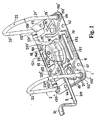
Fig. 1 is a perspective front view of the assembly in its closed state; -
Fig. 2 is a perspective view from the opposite side, also in the closed state, -
Fig. 3 is a side view of the same assembly in the closed state thereof; -
Fig. 4 shows the assembly in the same view as in theFig. 1 , however in its opened state; -
Fig. 5 is a front view of the assembly in its opened state; -
Fig. 6 is a schematic presentation of loading and deformation performances of the swiveling part of the clipping set of the assembly according to the state of the art; and -
Fig. 7 is a schematic presentation of loading and deformation performances of the swiveling part of the clipping set of the assembly according to the invention. - A clipping assembly of a document file, which has been created in accordance with the present invention and is shown in the drawings, consists of a
base plate 1, on which a clipping set 2 is arranged, which can be placed in each desired position by means ofappropriate actuation set 3. - The
base plate 1 consists of an essentially uniform part of a cold-formed metal plate having slightly roundedcorner areas 110', 110", 120', 120" and comprising appropriate positioning means 10', 10", which are by this particular embodiment available as round bores and serve exclusively for the purpose of positioning during performing required steps in the process of manufacturing thebase plate 1 and/or completing the assembly, while on the other hand, the said means have no essential influence with regard to functioning of the assembly as such. - On the
side 11 of thebase plate 1, where clipping of the documents into the assembly occurs, twoseats 112', 112" are available in thecorner areas 110', 110" adjacent to the correspondinglongitudinal edge 111, which serve for attaching the belonging parts of the clipping set 2, which will be disclosed in more detail in the further description. On theopposite side 12 of thebase plate 1appropriate bearings 122', 122" are arranged closely to the belongingcorner areas 120', 120" adjacent to thelongitudinal edge 121, which serve for pivotable attaching the belonging parts of the clipping set 2, which will also will be disclosed in mored detail in the further description. The saidbearings 122', 122" are in this particular embodiment established by means of cutting-off trapezoidal parts of the material of thebase plate 1 and bending thereof during assembling in the direction towards the belonginglongitudinal edge 121 of thebase plate 1, so that at least approximately cyllindrical passage is formed inside of each bearing 122', 122". Acantilever 14 is arranged in thecentral area 16 of thebase plate 1, which comprises aswiveling point 140 adapted for cooperation with the actuation set 3, which will be disclosed later. Also the saidcantilever 14 is formed by means of cutting-off material of thebase plate 1 and deflecting thereof from the level of the saidbase plate 1 into another position, which is shown in the enclosed drawing. As evident, thecantilever 14 is bent into an inclined position, and actually extends almost perpendicularly with respect to the surface of thebase plate 1. In addition, thebase plate 1 in this particular embidiment comprises fourbores - The clipping set 2 consists of a
stable part 21 which is formed bystable pins 21', 21", as well as of amovable part 22, which is pivotable attached onto thebase plate 1 and comprisespivotable pins 22', 22". - Each of the said
stable pins 21', 21" consists of a metal wire or rod having circular or at least essentially circular cross-section, and is in the area of the saidseats 112', 112" fixed in a non-detachable manner onto the saidbase plate 1, extending thereby at least essentially perpendicularly with respect to the saidbase plate 1. With respect to thebase plate 1utmost portions 210', 210" of thepins 21', 21" are slightly bended towards the belongingpins 22', 22" of thepivotable part 22 of the clipping set 2. - At least in this particular embodiment, the
pivotable part 22 of the clipping set 2 also consists of a metal wire or rod having circular or at least essentially circular cross-section. It is important, that the saidpivotable part 22 is adapted for pivotable attachment onto thebase plate 1 as well as for appropriate cooperation with the actuation set 3, and especially also for coaxial alignment ofpivotable pins 22', 22" with respect to thestable pins 21', 21" in the closed state of the assembly as shown in theFigs. 1 to 3 . Accordingly, the discussedpivotable part 22 comprises two coaxially extending, but in the axial direction separately arranged linear guidingportions 221', 221", which are adapted for insertion intocorresponding bearings 122', 122" on thebase plate 1, and furthermore also a linearcentral portion 222, and moreover also twopivotable pins 22', 22", which extend at least essentially perpendicularly with respect to the saidbase plate 1 and on the desired distance therefrom, and are slightly bent towards to the belongingstable pins 21', 21 ".Intermediate portions 223', 223", which are lying between the saidcentral portion 22 and each belonging guidingportion 221', 221", extend inclined from each corresponding guidingportion 221', 221" to thecentral portion 222. - The said
guide portions 221', 221" of thepivotable part 22 of the clipping set 2 extend coaxially each to another and moreover also at least essentially parallel with respect to the adjacentlongitudinal edge 121 of thebase plate 1, and are moreover separately inserted into the belongingbearings 122', 122" as available on thebase plate 1, by which thepivotable part 22 of the clipping set 2 may be swiveled with respect to thebase plate 1 and also to thestable pins 21', 21" for a desired angle, which as a matter of fact enables opening or closing the assembly according to the invention, as evident in theFigs. 3 and5 . - The said
central portion 222 is adapted for establishing cooperation between thepivotable part 22 and theactuating set 3. Thecentral portion 222 extends at least essentially parallel and non-coaxially with respect to the said guidingportions 221', 221". Such embodiment may be achieved by means of trapezoidal bending of the material of thepivotable part 22 of the clipping set 2, which is visible in the enclosed drawing as well as in the documents belonging to the prior art. It is important, that thepivotable part 22 of the clipping set 2 is supported in the area of thecentral portion 222 by means of aspring 23, which is attached to thebase plate 1 and intended for establishing a required pressure against thepivotable part 22 in thecentral portion 222 thereof, the consequence of which is a springy supported swiveling of thepivotable part 22 of the clipping set 2 on thebase plate 1. - The actuating set 3 of the assembly according to the invention comprises a double-
arm actuating lever 31, which consists of alonger arm 311 and ashorter arm 312 as well as of appropriatepressing means 313. The saidlonger arm 311 is intended for establishing a required force in a desired direction, which is required for opening or closing the assembly as such, namely for displacing thepivotable part 22 of the clipping set 2. The saidlever 31 is pivotably attached to the saidswiveling point 140 on thecantilever 14 on thebase plate 1 by means of itslonger arm 312, where the maximum declination of thearm 31 is determined by the position of a limitation means 141, which is foreseen on thecantilever 14 and formed as a protrusion or deflection on the surface of thecantilever 14 faced towards thelever 31. The saidpressing means 313 is arranged at least essentially in the area of coinciding the saidarms lever 31, and is in the discussed embodiment formed by a rollingelement 3130, which is freely turnable placed on the belongingpivot 3131 1 arranged on the saidlever 31. - In
Figs. 4 and5 , the clipping assembly is shown in its opened state, into which any desired documents may be inserted, which must however be previously perforated in appropriate manner, namely depending on the distance between thepins 21', 21". The stable pins 21', 21" are fixed on thebase plate 1, while thepivotable part 22 of the clipping set 2 is swiveled away due to the pressure of thespring 23, so that thepivotable pins 22', 22" are placed at a certain distance from thestable pins 21', 21". Thelever 31 of the acuating set 3 is swiveled into its end position at the maximal distance from thebase plate 1, and the rollingelement 3130 of thepressing means 313 is rest onto thecentral portion 222 of thepivotable part 22 of the clipping set 2, while thelever 31 of the actuating set 3 is rest on the limitation means 141 of thecantilever 14 of thebase plate 1, so that any further swiveling of thelever 31 due to the pressure of thespring 23 against thepivotable part 22 of the clipping set 2 is disabled. - By sinking the
lever 31 towards thebase plate 1, itsshorter arm 312 is swiveled arround theswiveling point 140, while thepressing means 313 ensures a required pressure against thecentral portion 222 of thepivotable set 2, by which therolling element 3130 is moved along the saidportion 222, which - thanks to pressing against the spring 23 - results in swiveling thepivotable part 22 of the clipping set 2. By such swiveling of the clipping set 2 within thebearings 122', 122", the pivotable pins 22', 22" are moved towards thestable pins 21', 21". However, before thepressing means 313 reaches its lowest position during the said movement, i.e. a position, in which theshorter arm 312 extends perpendicularly with respect to the plane of thebase plate 1, the pivotable pins 22', 22" arrive in abutment with thestable pins 21', 21". In such a state, the assembly is practically closed, but cannot be maintained in such position, since due to the effect of thespring 23 upon termination of pressing the lever 3I, the assembly would be automatically opened again. In order to exclude such undesired opening of assembly, some further movement of the said pressing means 313 over the lowest position has to be ensured, whereupon theshorter arm 312 of thelever 31 is held in a position, in which at the one hand it is pressed byspring 23 from thebase plate 1 away, while on the other hand by pressingpivotable pins 22', 22" against thestable pins 21', 21" any further swiveling of thepivotable part 22 of the clipping set 2 is impossible. Such arresting of the actuating set 3 is achieved thanks to formation of thelever 31, i.e. due to excentric arrangement of the pressing means 313 with respect to pivotable placing thelever 31 in theswiveling point 140 of thecantilever 14 of thebase plate 1. Due to elasticity of thecanteliver 14, the deformations may be compensated, which occur during the whole period of abutting pivotable pins 22', 22" against thestable pins 21', 21" when moving the pressing means 313 over the lowest point. - Various loadings are transferred to the
base plate 1 during compensation of these deformations resulting from arresting the clipping assembly. In addition, by abutting pivotable pins 22', 22" against thestable pins 21', 21", thebase plate 1 is exposed to essential bending arround its longitudinal axis lying between thelongitidinal edges pivotable part 22, there is a tendency of setting asunder i.e. opening both pairs of thepins 21', 22' and 21", 22", the result of which is a tendency of bending the central areas of thelongitudinal edges base plate 1 from the ground away, i.e. perpendicularly with respect to the corresponding plane of the ground. - The loadings occuring on the
pivotable part 22 of the clipping set 2 are schematically shown in theFig. 6 . Thepivotable part 22 is presented in its unloaded state by means of a thickened line, while thesame part 22 is shown by means of a dotted line in its loaded and adequately deformed state. The saidpivotable part 22 is loaded in itscentral part 222 by means of the force F, which is a consequence of resting the pressing means 313 of the actuating set 3 against the central portion of thepivotable part 22 of the clipping set 2 in that moment, when the saidpressing means 313 is moved into its lower position, the closest to thebase plate 1. The forces R1 and R2 are reaction forces, by which the pivotable part is loaded in the area of itsportions 221', 221" as placed in the correspondingbearings 122', 122" on thebase plate 1. Thepivotable part 22 is exposed to bending stresses, and itsins 22', 22" in such a state show the tendency of moving one towards another. Deformations of such kind may result damages on documents, which are stored within the document file. - On the other hand, when the
pivotable part 22 is exposed to the above specified loadings, thebase plate 1 is exposed to bending stresses as a consequence of the force resulting from resting the pressing means 313 against thecentral portion 222 of thepivotable part 22 of the clipping set 2. This force is transferred via theswiveling point 140 onto thecantilever 14 acting thereby in the direction away from thebase plate 1, so that thebase plate 1 shows the tendency of bending, namely deflecting thecentral area 16 below thecantilever 14 in the direction from the ground away, as well as deflecting central portions of thelongitudinal edges - In order to avoid such situation, reinforcing
elevations 15', 15" are arranged on thebase plate 1 in the area of restingintermediate portions 223', 223", which are in this particular embodiment formed in a quite simple manner in form of pressed protrusions. The main purpose of improving thebase plate 1 by means of theseelevations 15', 15" is to ensure appropriate resting ofintermediate portions 223', 223" of thepivotable part 22 of the clipping set 2 onto the saidelevations 15', 15" each time, when thebase plate 1 is exposed to maximum stresses by moving the pressing means 313 into the lowest position and abutting the pivotable pins 22', 22" towards thestable pins 21', 21". In such a way, deformations of thepivotable part 22 of the clipping set 2 and also of thebase plate 1 as such are essentially reduced in this state when being exposed to maximal stresses. -
Figs. 6 and 7 show the situation related to loadings and deformation of thepivotable part 22 of the clipping set 2, when resting onto the saidelevations 15', 15". In this situation, reduced forces r1 and r2 occur in the area ofbearings 122', 122" instead of the former reaction forces (R1 and R2 according toFig. 6 ) in the opposite direction, and opposite with respect to them, in the area of the saidelevations 15', 15" the other forces P1 and P2 are available, which are indeed some stronger, but are thanks to their direction in such situation essentially easier acceptable. Accordingly, deformation of thepins 22', 22" is essentially reduced. - At the same time, the described loading situation brings essential benefits also when bearing in mind the loadings and deformations occuring by the base plate I itself. Due to pressing the
intermediate portions 223', 223" of thepivotable part 22 of the cliping set 2 towards theelevations 15', 15", bending of thebase plate 1 in this area may be essentially reduced. - In addition, the
central portion 16 of thebase plate 1 arround thecantilever 14 is equipped with an elevatedsurrounding bow 160, so that the saidportion 16 is elevated and lies above the other areas of thebase plate 1, and is in fact arranged as the top portion of thebase plate 1. - A further measure in course of essentially reduction or elimination deformations of the
base plate 1 in sense of deflecting thelongitudinal edges means - The first longitudinal reinforcing
means 17 is arranged adjacent to thelongitudinal edge 11 lying on the same side of thebase plate 1 as thestable pins 21', 21". The said reinforcingmeans 17 consists of arib 171, extending at least essentially parallel with respect to the belongingedge 111 of the base plate, as well as of agroove 172 in its adjacency, which also extends in the longitudinal direction of thebase plate 1. - Still further longitudinal reinforcing
means 18 is arranged on the opposite side of thebase plate 1, consisting thereby of two separate colinearly directedgrooves base plate 1, i.e. at least esentially parallel with respect to at least one of thelongitudinal edges base plate 1. - In order to further reduce deformations of the
base plate 1, which result from bending thereof arround its longitudinal axis being parallel to thelongitudinal edges transversal reinforcing means 19', 19" are foreseen. These reinforcing means 19', 19" are arranged among each correspondingstable pin 21', 21" andpivotable pin 22', 22" as well as thecentral portion 16. In this particular embodiment, the transversal reinforcingmeans 19', 19" are arranged arround the positioning means 10', 10". Each of these reinforcingmeans 19', 19 is available in form of a curved or knicked groove, thecentral section 191', 191" of which extends in the longitudinal direction of thebase plate 1, and coincides with the belongingend sections 192', 192" and 193', 193". In this particular embodiment, thecentral section 191', 191" of the transversal reinforcingmeans 19', 19" is arranged on such side of the positioning means 10', 10", which is arranged closely to thestable pins 21', 21", while theend sections 192', 192" and 193', 193" extends on each side of the positioning means 10', 10" towards thebearings 122', 122" in a slightly inclined direction each towards another without coinciding each to another. - Thanks to a described construction of the
base plate 1, comprising the saidelevations 15', 15", the elevatedcentral portion 16 with thesurrounding bow 160 above thecantilever 14, as well as the longitudinal reinforcingmeans - The said
elevations 15', 15" are preferably available in form of pressed protrusions, but may also be formed e.g. by means of cutting-out and subsequently bending a part of the material of thebase plate 1, or also as a nipple or any other protrusion, which may be attached to thebase plate 1 in a relevant area thereof either by means of welding or riveting or in any other similar mathod of attaching. Although it is preferred, that the belongingelevation 15', 15" is available below each of the said twointermediate portions 223', 223" of thepivotable part 22 of the clipping set 2 asingle elevation 15', 15", it is also possible to arrange elevations below the guidingportions 221', 221" of thepivotable part 22 of the clipping set 2. In such case, the longitudinal reinforcing means 181, 182 needs not to be present on thebase plate 1. - Some experimental results may also be presented in order to enable practical evaluation of essential benefits, which result from the solution according to the invention in course of essential reduction of deformations of the
base plate 1. When observing.a 7,5 cm in width document file equipped with the clipping assembly according toEP 0 114 654 , the thickness of a steel plate used by manufacturing thebase plate 1 has to be approximately 0,8 mm, if the deformations occuring by regular use should be kept within the acceptable limits. In the identical circumstances with respect to dimensions of the document file and loadings, to which it is exposed, thebase plate 1 according to the invention needs to be manufactured of a steel plate having thickness only approx. 0,6 mm in order to keep the deformations within the same range as by the previously mentioned known base plate according to prior art. Those skilled in the art will understand, that such an essential reduction of thickness of the material used bymanufacturing base plates 1 enables achieving various benefits, not only the cost reduction with respect to material consumption, but also in sense of an essential reduction of loadings occuring during the manufacturing process by manufacturing requisites, by which an essential extension of life-time of the tools, reduction of maintenance-related costs, costs of lubrication and surface protection, as well as in various other indirect benefits may be achieved.
Claims (18)
- Clipping assembly of a document file, which is especially intended for attaching to the interior surface of the rear cover of a document file and consists of a base plate (1), a clipping set (2) and an actuating set (3),
whereas the base plate (1) may also comprise, in addition to attaching openings (41, 42, 43, 44), appropriate positioning means (10', 10"), which may be arranged adjacent to the central portion (16), where an essentially inclined, with respect to the plane of the base plate (1) almost perpendicularly directed cantilever (14) is available, which is equipped with a swiveling point (140) and a limitation means (141) adapted for cooperation with the actuating set (3),
and whereas the springly supported clippping set (2) consists of at least two stable pins (21', 21 "), which are mounted in a non-detachable manner onto the base plate (1) adjacent to the belonging longitudinal edge (111), as well as of a pivotable part (2), which is by means of its coaxially arranged guiding portions (221', 221") pivotable inserted within appropriate bearings (122', 122") arranged in adjacency of the other longitudinal edge (121) of the base plate (1), and comprises at least two pivotable pins (22', 22"), which are adapted for cooperation with the said stable pins (21', 21") in sense of pressing each pivotable pin (22', 22") against each belonging stable pin (21', 21"), as well as a linear central portion (222) extending parallel with respect to the said guiding portions (221', 221") and adapted for cooperation with the said actuating set (3), while inclined intermediate portions (223', 223") are available between the said central portion (222) and the said guiding portions (221', 221"),
and whereas the actuating set (3) consists of a double-arm actuating lever (31), the longer arm (311) of which serves for ensuring a force, which is required for moving the assembly from opened to closed position thereof or vice-versa, while its shorter arm (312) is pivotable connected to the cantilever (14) in the swiveling point (140) and equipped with a pressing means (313) intended for resting on the central portion (222) of the clipping set (2) in sense of pressing in opposite direction with regard to the force resulting from a spring (23), by means of which the said pivotable part (2) is supported on the base plate (1) and simultaneously in a pivotable manner inserted within the bearings (122', 122"),
characterized in that
the base plate (1) comprises at least one elevation (15', 15") arranged in the area below each intermediate portion (223', 223") between the central portion (222) and each belonging guiding portion (221', 221") and/or below each belonging guiding portion (221', 221") of the clipping set (2), and that the central portion (16) of the base plate (1) below the cantilever (14) is elevated above the other areas of the base plate (1) by means of a surrounding bow (160), which extends along at least a part of the circumference of the said portion. - Clipping assembly according to Claim 1, characterized in that the base plate (1) comprises at least one elevation (15', 15") arranged in the area below each intermediate portion (223', 223") between the central portion (222) and each belonging guiding portion (221', 221 ") of the clipping set (2), and that the central portion (16) of the base plate (1) below the cantilever (14) is elevated above the other areas of the base plate (1) by means of a surrounding bow (160), which extends along at least a part of the circumference of the said portion.
- Clipping assembly according to Claim 2, characterized in that the base plate (1), in addition to the said elevations (15', 15") as well as to the elevated and with the bow (160) at least partially surrounded central portion (16), comprises at least one longitudinal reinforcing means (17, 18).
- Clipping assembly according to Claim 1 or 2, characterized in that the base plate (1), in addition to the said elevations (15', 15") as well as to the elevated and with the bow (160) at least partially surrounded central portion (16), comprises at least one transversal reinforcing means (19', 19").
- Clipping assembly according to Claim 1 or 2, characterized in that the base plate (1), in addition to the said elevations (15', 15") as well as to the elevated and with the bow (160) at least partially surrounded central portion (16), comprises at least one longitudinal reinforcing means (17, 18) and also at least one transversal reinforcing means (19', 19").
- Clipping assembly according any of Claims 2 to 5, characterized in that in the area below the intermediate portions (223', 223") of the pivotable part (22) of the clipping set (2), appropriate elevations (15', 15") are available on the base plate (1), which are with respect to their height adapted for resting the belonging intermediate portion (223', 223"), which is available between the central portion (222) and the belonging guiding portion (221', 221"), onto the belonging one of said elevations (15', 15") during the maximal loading, which occurs by passing the pressing means (313) of the actuating set (3) over the lowest point i.e. the point of minimal distance thereof with respect to the base plate (1).
- Clipping assembly according any of Claims 2 to 5, characterized in that in the central portion (16) below the cantilever (14) equipped with the swiveling point (140) of the double-arm lever (31) of the actuating set (3), the base plate (1) comprises a bow (160), thanks to which the said central portion (160) is elevated with respect to other areas of the base plate (1).
- Clipping assembly according to Claim 3 and/or 5, characterized in that the base plate (1) comprises at least one longitudinal reinforcing means (17) consisting of a rib (171) extending along the base plate (1), as well as of a groove (172) extending parallel with respect to the said rib.
- Clipping assembly according to Claim 8, characterized in that the base plate (1) comprises at least one longitudinal reinforcing means (17), which is arranged adjacent to the longitudinal edge (111) closely to the stable pins (21', 21").
- Clipping assembly according to Claim 3 and/or 5, characterized in that the base plate (1) comprises at least one longitudinal reinforcing means (18), consisting of two separate grooves (181, 182) extending co-linearly at least approximately in the longitudinal direction of the base plate (1), namely at least essentially parallel with respect to at least one of the longitudinal edges (111, 121) of the base plate (1).
- Clipping assembly according to Claim 10, characterized in that the base plate (1) comprises a longitudinal reinforcing means (18), which is arranged adjacent to the edge (121) close to the bearings (122', 122") of the pivotable part (22) of the clipping set (2).
- Clipping assembly according to Claim 4 and/or 5, characterized in that the base plate (1) comprises at least one transversal reinforcing means (19', 19") in form of a knicked groove, which extends among each corresponding stable pin (21', 21") and pivotable pin (22', 22") as well as the elevated central portion (16) of the base plate (1).
- Clipping assembly according to Claim 4 and/or 5, characterized in that the base plate (1) comprises at least one transversal reinforcing means (19', 19") in form of a knicked groove, which is arranged adjacent to the positioning means (10', 10"), and which at least partially surrounds the said positioning means (10', 10").
- Clipping assembly according to Claim 4 and/or 5, characterized in that the base plate (1) comprises at least one transversal reinforcing means (19', 19") in form of a knicked groove, which consists of a central portion (191', 191") extending at least approximately in the longitudinal direction of the base plate (1) i.e. at least approximately parallel with respect to at least one of the longitudinal edges (111, 121) of the base plate (1), as well as of end portions (192', 192"; 103', 193"), which coincide with the said central portions (191', 191") extending thereby in the direction towards the belonging bearing (122', 122") of the pivotable part (22) of the clipping set (2), and converging each to other without coincidence.
- Clipping assembly according to Claim 4 and/or 5, characterized in that the base plate (1) comprises two reinforcing means (19', 19"), each of them at least partially surrounds the belonging positioning means (10', 10") and is available in form of a knicked groove, which consists of a central portion (191', 191") extending at least approximately in the longitudinal direction of the base plate (1) i.e. at least approximately parallel with respect to at least one of the longitudinal edges (111, 121) of the base plate (1), as well as of end portions (192', 192"; 103', 193"), which coincide with the said central portions (191', 191") extending thereby in the direction towards the belonging bearing (122', 122") of the pivotable part (22) of the clipping set (2), and converging each to other without coincidence.
- Clipping assembly according to Claim 1, characterized in that the base plate (1) comprises at least one elevation (15', 15") arranged in the area below each belonging guiding portion (221', 221 ") of the clipping set (2), and that the central portion (16) of the base plate (1) below the cantilever (14) is elevated above the other areas of the base plate (1) by means of a surrounding bow (160), which extends along at least a part of the circumference of the said portion.
- Clipping assembly according to Claims 1 and 16, characterized in that the base plate (1), in addition to the elevations (15', 15") as well as to the elevated and with the bow (160) at least partially surrounded central portion, comprises also at least one longitudinal reinforcing means (17), which is arranged adjacent to the longitudinal edge (111) of the base plate (1) closely to the stable pins (21', 21").
- Clipping assembly according to Claim 17, characterized in that the longitudinal reinforcing means (17) consists of a rib (171) extending along the base plate (1), as well as of a groove (172) extending parallel with respect to the said rib.
Applications Claiming Priority (3)
| Application Number | Priority Date | Filing Date | Title |
|---|---|---|---|
| SI200300067A SI21455A (en) | 2003-03-18 | 2003-03-18 | Clamping mechanism for folders |
| SI200300067 | 2003-03-18 | ||
| PCT/SI2003/000011 WO2004082961A1 (en) | 2003-03-18 | 2003-04-16 | Clipping assembly of a document file |
Publications (2)
| Publication Number | Publication Date |
|---|---|
| EP1606122A1 EP1606122A1 (en) | 2005-12-21 |
| EP1606122B1 true EP1606122B1 (en) | 2008-05-21 |
Family
ID=33029197
Family Applications (1)
| Application Number | Title | Priority Date | Filing Date |
|---|---|---|---|
| EP03816385A Expired - Lifetime EP1606122B1 (en) | 2003-03-18 | 2003-04-16 | Clipping assembly of a document file |
Country Status (6)
| Country | Link |
|---|---|
| EP (1) | EP1606122B1 (en) |
| AT (1) | ATE396064T1 (en) |
| AU (1) | AU2003235406A1 (en) |
| DE (3) | DE60321234D1 (en) |
| SI (1) | SI21455A (en) |
| WO (1) | WO2004082961A1 (en) |
Cited By (1)
| Publication number | Priority date | Publication date | Assignee | Title |
|---|---|---|---|---|
| WO2011149430A1 (en) | 2010-05-24 | 2011-12-01 | Niko, Kovinarsko Podjetje, D.D., Zelezniki | Document file ring mechanism with improved base plate |
Families Citing this family (5)
| Publication number | Priority date | Publication date | Assignee | Title |
|---|---|---|---|---|
| GB2422806B (en) * | 2004-11-29 | 2007-01-31 | Soon Huat Lim | Lever arch mechanism |
| SI22833B (en) | 2007-12-18 | 2011-10-28 | NIKO, Kovinarsko podjetje, d.d., Železniki | Control mechanism of ring binder with two-part handle |
| SI22707A (en) | 2008-01-22 | 2009-08-31 | NIKO, Kovinarsko podjetje, d.d., Železniki | Clamping mechanism of file |
| SI23726A (en) | 2011-05-20 | 2012-11-30 | NIKO@@Kovinarsko@podjetje@@d@d@@@Železniki | Locking mechanism of registrar |
| SI23795A (en) | 2011-07-13 | 2013-01-31 | NIKO, Kovinarsko podjetje d.o.o., Železniki | Simplified file mechanism |
Family Cites Families (1)
| Publication number | Priority date | Publication date | Assignee | Title |
|---|---|---|---|---|
| DE3302268C2 (en) * | 1983-01-25 | 1984-12-13 | Leitz, Louis, 7000 Stuttgart | Base plate of a line-up device |
-
2003
- 2003-03-18 SI SI200300067A patent/SI21455A/en not_active IP Right Cessation
- 2003-04-16 DE DE60321234T patent/DE60321234D1/en not_active Expired - Lifetime
- 2003-04-16 AT AT03816385T patent/ATE396064T1/en not_active IP Right Cessation
- 2003-04-16 AU AU2003235406A patent/AU2003235406A1/en not_active Abandoned
- 2003-04-16 DE DE20321091U patent/DE20321091U1/en not_active Expired - Lifetime
- 2003-04-16 EP EP03816385A patent/EP1606122B1/en not_active Expired - Lifetime
- 2003-04-16 DE DE20380284U patent/DE20380284U1/en not_active Expired - Lifetime
- 2003-04-16 WO PCT/SI2003/000011 patent/WO2004082961A1/en not_active Ceased
Cited By (1)
| Publication number | Priority date | Publication date | Assignee | Title |
|---|---|---|---|---|
| WO2011149430A1 (en) | 2010-05-24 | 2011-12-01 | Niko, Kovinarsko Podjetje, D.D., Zelezniki | Document file ring mechanism with improved base plate |
Also Published As
| Publication number | Publication date |
|---|---|
| EP1606122A1 (en) | 2005-12-21 |
| WO2004082961A1 (en) | 2004-09-30 |
| DE60321234D1 (en) | 2008-07-03 |
| SI21455A (en) | 2004-10-31 |
| DE20380284U1 (en) | 2005-06-23 |
| AU2003235406A1 (en) | 2004-10-11 |
| ATE396064T1 (en) | 2008-06-15 |
| DE20321091U1 (en) | 2005-11-10 |
Similar Documents
| Publication | Publication Date | Title |
|---|---|---|
| DE19537898C2 (en) | Original press device for copiers | |
| CN1067635C (en) | ring binder | |
| EP1568509A2 (en) | Ring binder mechanism | |
| HK1054356A1 (en) | Ring binder mechanism | |
| EP1606122A1 (en) | Clipping assembly of a document file | |
| CN101450562A (en) | Ring binder mechanism with polymer housing and actuator | |
| CN102216088A (en) | Documentation Systems, Booklets & Binders | |
| US20090067915A1 (en) | Ring binder | |
| GB2037199A (en) | Brake for bending sheet material | |
| US20070140779A1 (en) | Ring Binder Mechanism | |
| GB2209500A (en) | Ring binder mechanism | |
| EP0653536B1 (en) | Hinge Assembly | |
| CN1070122C (en) | Binding assembly for binders | |
| US7293932B2 (en) | Lever arch binder mechanism with complementary ring tips | |
| EP1203670A2 (en) | A ring binder mechanism | |
| CA2345185A1 (en) | A blanking platen in a shaping press | |
| EP2219881B1 (en) | File mechanism having a double lever | |
| EP2237970B1 (en) | Lever arch file comprising an element inserted between the lever and the arch | |
| EP2576236B1 (en) | Document file ring mechanism with improved base plate | |
| DE2931158C2 (en) | Stringing mechanism | |
| WO2013009265A1 (en) | File mechanism | |
| CN1156092A (en) | Sheet clip | |
| EP2479039A2 (en) | Paper-retaining mechanism | |
| HK1024890A (en) | A ring binder mechanism | |
| SK69895A3 (en) | Shunting mechanics for perforated sheat |
Legal Events
| Date | Code | Title | Description |
|---|---|---|---|
| PUAI | Public reference made under article 153(3) epc to a published international application that has entered the european phase |
Free format text: ORIGINAL CODE: 0009012 |
|
| 17P | Request for examination filed |
Effective date: 20051018 |
|
| AK | Designated contracting states |
Kind code of ref document: A1 Designated state(s): AT BE BG CH CY CZ DE DK EE ES FI FR GB GR HU IE IT LI LU MC NL PT RO SE SI SK TR |
|
| AX | Request for extension of the european patent |
Extension state: AL LT LV MK |
|
| DAX | Request for extension of the european patent (deleted) | ||
| RIN1 | Information on inventor provided before grant (corrected) |
Inventor name: KAVCIC, BORIS Inventor name: MOLE, NIKOLAJ Inventor name: POKORN, MIRAN Inventor name: HALILOVIC, MIROSLAV Inventor name: KOC, PINO Inventor name: STOK, BORIS |
|
| GRAP | Despatch of communication of intention to grant a patent |
Free format text: ORIGINAL CODE: EPIDOSNIGR1 |
|
| GRAS | Grant fee paid |
Free format text: ORIGINAL CODE: EPIDOSNIGR3 |
|
| GRAA | (expected) grant |
Free format text: ORIGINAL CODE: 0009210 |
|
| AK | Designated contracting states |
Kind code of ref document: B1 Designated state(s): AT BE BG CH CY CZ DE DK EE ES FI FR GB GR HU IE IT LI LU MC NL PT RO SE SI SK TR |
|
| REG | Reference to a national code |
Ref country code: GB Ref legal event code: FG4D |
|
| REG | Reference to a national code |
Ref country code: CH Ref legal event code: EP |
|
| REF | Corresponds to: |
Ref document number: 60321234 Country of ref document: DE Date of ref document: 20080703 Kind code of ref document: P |
|
| REG | Reference to a national code |
Ref country code: IE Ref legal event code: FG4D |
|
| PG25 | Lapsed in a contracting state [announced via postgrant information from national office to epo] |
Ref country code: SI Free format text: LAPSE BECAUSE OF FAILURE TO SUBMIT A TRANSLATION OF THE DESCRIPTION OR TO PAY THE FEE WITHIN THE PRESCRIBED TIME-LIMIT Effective date: 20080521 |
|
| PG25 | Lapsed in a contracting state [announced via postgrant information from national office to epo] |
Ref country code: FI Free format text: LAPSE BECAUSE OF FAILURE TO SUBMIT A TRANSLATION OF THE DESCRIPTION OR TO PAY THE FEE WITHIN THE PRESCRIBED TIME-LIMIT Effective date: 20080521 Ref country code: ES Free format text: LAPSE BECAUSE OF FAILURE TO SUBMIT A TRANSLATION OF THE DESCRIPTION OR TO PAY THE FEE WITHIN THE PRESCRIBED TIME-LIMIT Effective date: 20080901 |
|
| NLV1 | Nl: lapsed or annulled due to failure to fulfill the requirements of art. 29p and 29m of the patents act | ||
| PG25 | Lapsed in a contracting state [announced via postgrant information from national office to epo] |
Ref country code: NL Free format text: LAPSE BECAUSE OF FAILURE TO SUBMIT A TRANSLATION OF THE DESCRIPTION OR TO PAY THE FEE WITHIN THE PRESCRIBED TIME-LIMIT Effective date: 20080521 Ref country code: AT Free format text: LAPSE BECAUSE OF FAILURE TO SUBMIT A TRANSLATION OF THE DESCRIPTION OR TO PAY THE FEE WITHIN THE PRESCRIBED TIME-LIMIT Effective date: 20080521 |
|
| PG25 | Lapsed in a contracting state [announced via postgrant information from national office to epo] |
Ref country code: SE Free format text: LAPSE BECAUSE OF FAILURE TO SUBMIT A TRANSLATION OF THE DESCRIPTION OR TO PAY THE FEE WITHIN THE PRESCRIBED TIME-LIMIT Effective date: 20080821 Ref country code: DK Free format text: LAPSE BECAUSE OF FAILURE TO SUBMIT A TRANSLATION OF THE DESCRIPTION OR TO PAY THE FEE WITHIN THE PRESCRIBED TIME-LIMIT Effective date: 20080521 Ref country code: PT Free format text: LAPSE BECAUSE OF FAILURE TO SUBMIT A TRANSLATION OF THE DESCRIPTION OR TO PAY THE FEE WITHIN THE PRESCRIBED TIME-LIMIT Effective date: 20081021 |
|
| PG25 | Lapsed in a contracting state [announced via postgrant information from national office to epo] |
Ref country code: BE Free format text: LAPSE BECAUSE OF FAILURE TO SUBMIT A TRANSLATION OF THE DESCRIPTION OR TO PAY THE FEE WITHIN THE PRESCRIBED TIME-LIMIT Effective date: 20080521 Ref country code: RO Free format text: LAPSE BECAUSE OF FAILURE TO SUBMIT A TRANSLATION OF THE DESCRIPTION OR TO PAY THE FEE WITHIN THE PRESCRIBED TIME-LIMIT Effective date: 20080521 Ref country code: SK Free format text: LAPSE BECAUSE OF FAILURE TO SUBMIT A TRANSLATION OF THE DESCRIPTION OR TO PAY THE FEE WITHIN THE PRESCRIBED TIME-LIMIT Effective date: 20080521 |
|
| PLBE | No opposition filed within time limit |
Free format text: ORIGINAL CODE: 0009261 |
|
| STAA | Information on the status of an ep patent application or granted ep patent |
Free format text: STATUS: NO OPPOSITION FILED WITHIN TIME LIMIT |
|
| 26N | No opposition filed |
Effective date: 20090224 |
|
| PG25 | Lapsed in a contracting state [announced via postgrant information from national office to epo] |
Ref country code: BG Free format text: LAPSE BECAUSE OF FAILURE TO SUBMIT A TRANSLATION OF THE DESCRIPTION OR TO PAY THE FEE WITHIN THE PRESCRIBED TIME-LIMIT Effective date: 20080821 Ref country code: EE Free format text: LAPSE BECAUSE OF FAILURE TO SUBMIT A TRANSLATION OF THE DESCRIPTION OR TO PAY THE FEE WITHIN THE PRESCRIBED TIME-LIMIT Effective date: 20080521 |
|
| REG | Reference to a national code |
Ref country code: CH Ref legal event code: PL |
|
| REG | Reference to a national code |
Ref country code: FR Ref legal event code: ST Effective date: 20091231 |
|
| PG25 | Lapsed in a contracting state [announced via postgrant information from national office to epo] |
Ref country code: CZ Free format text: LAPSE BECAUSE OF NON-PAYMENT OF DUE FEES Effective date: 20090416 Ref country code: CH Free format text: LAPSE BECAUSE OF NON-PAYMENT OF DUE FEES Effective date: 20090430 Ref country code: LI Free format text: LAPSE BECAUSE OF NON-PAYMENT OF DUE FEES Effective date: 20090430 |
|
| REG | Reference to a national code |
Ref country code: IE Ref legal event code: MM4A |
|
| PG25 | Lapsed in a contracting state [announced via postgrant information from national office to epo] |
Ref country code: FR Free format text: LAPSE BECAUSE OF NON-PAYMENT OF DUE FEES Effective date: 20091222 Ref country code: MC Free format text: LAPSE BECAUSE OF NON-PAYMENT OF DUE FEES Effective date: 20090430 Ref country code: IE Free format text: LAPSE BECAUSE OF NON-PAYMENT OF DUE FEES Effective date: 20090416 |
|
| PG25 | Lapsed in a contracting state [announced via postgrant information from national office to epo] |
Ref country code: GR Free format text: LAPSE BECAUSE OF FAILURE TO SUBMIT A TRANSLATION OF THE DESCRIPTION OR TO PAY THE FEE WITHIN THE PRESCRIBED TIME-LIMIT Effective date: 20080822 |
|
| PG25 | Lapsed in a contracting state [announced via postgrant information from national office to epo] |
Ref country code: LU Free format text: LAPSE BECAUSE OF NON-PAYMENT OF DUE FEES Effective date: 20090416 |
|
| PGFP | Annual fee paid to national office [announced via postgrant information from national office to epo] |
Ref country code: IT Payment date: 20110315 Year of fee payment: 9 |
|
| PG25 | Lapsed in a contracting state [announced via postgrant information from national office to epo] |
Ref country code: HU Free format text: LAPSE BECAUSE OF FAILURE TO SUBMIT A TRANSLATION OF THE DESCRIPTION OR TO PAY THE FEE WITHIN THE PRESCRIBED TIME-LIMIT Effective date: 20081122 |
|
| PGFP | Annual fee paid to national office [announced via postgrant information from national office to epo] |
Ref country code: GB Payment date: 20110317 Year of fee payment: 9 |
|
| PG25 | Lapsed in a contracting state [announced via postgrant information from national office to epo] |
Ref country code: TR Free format text: LAPSE BECAUSE OF FAILURE TO SUBMIT A TRANSLATION OF THE DESCRIPTION OR TO PAY THE FEE WITHIN THE PRESCRIBED TIME-LIMIT Effective date: 20080521 |
|
| PG25 | Lapsed in a contracting state [announced via postgrant information from national office to epo] |
Ref country code: CY Free format text: LAPSE BECAUSE OF FAILURE TO SUBMIT A TRANSLATION OF THE DESCRIPTION OR TO PAY THE FEE WITHIN THE PRESCRIBED TIME-LIMIT Effective date: 20080521 |
|
| GBPC | Gb: european patent ceased through non-payment of renewal fee |
Effective date: 20120416 |
|
| PG25 | Lapsed in a contracting state [announced via postgrant information from national office to epo] |
Ref country code: GB Free format text: LAPSE BECAUSE OF NON-PAYMENT OF DUE FEES Effective date: 20120416 |
|
| PG25 | Lapsed in a contracting state [announced via postgrant information from national office to epo] |
Ref country code: IT Free format text: LAPSE BECAUSE OF NON-PAYMENT OF DUE FEES Effective date: 20120416 |
|
| PGFP | Annual fee paid to national office [announced via postgrant information from national office to epo] |
Ref country code: DE Payment date: 20220315 Year of fee payment: 20 |
|
| REG | Reference to a national code |
Ref country code: DE Ref legal event code: R071 Ref document number: 60321234 Country of ref document: DE |