EP1605560A2 - Lightemitting semiconductor device and method for temperature stabilisation - Google Patents
Lightemitting semiconductor device and method for temperature stabilisation Download PDFInfo
- Publication number
- EP1605560A2 EP1605560A2 EP05002961A EP05002961A EP1605560A2 EP 1605560 A2 EP1605560 A2 EP 1605560A2 EP 05002961 A EP05002961 A EP 05002961A EP 05002961 A EP05002961 A EP 05002961A EP 1605560 A2 EP1605560 A2 EP 1605560A2
- Authority
- EP
- European Patent Office
- Prior art keywords
- semiconductor device
- semiconductor
- heating element
- heating
- carrier
- Prior art date
- Legal status (The legal status is an assumption and is not a legal conclusion. Google has not performed a legal analysis and makes no representation as to the accuracy of the status listed.)
- Granted
Links
- 238000000034 method Methods 0.000 title claims abstract description 17
- 230000006641 stabilisation Effects 0.000 title claims abstract description 11
- 239000004065 semiconductor Substances 0.000 title claims description 249
- 238000010438 heat treatment Methods 0.000 claims abstract description 144
- 230000005855 radiation Effects 0.000 claims abstract description 25
- 238000011105 stabilization Methods 0.000 claims abstract description 10
- 238000001514 detection method Methods 0.000 claims description 17
- 238000005485 electric heating Methods 0.000 claims description 14
- 239000000463 material Substances 0.000 claims description 10
- 238000002513 implantation Methods 0.000 claims description 4
- 238000012544 monitoring process Methods 0.000 claims description 3
- 239000004020 conductor Substances 0.000 description 15
- 230000003287 optical effect Effects 0.000 description 7
- 239000000758 substrate Substances 0.000 description 7
- 230000003595 spectral effect Effects 0.000 description 5
- 230000001419 dependent effect Effects 0.000 description 4
- 238000000295 emission spectrum Methods 0.000 description 3
- 239000002184 metal Substances 0.000 description 3
- 229910001218 Gallium arsenide Inorganic materials 0.000 description 2
- 230000015572 biosynthetic process Effects 0.000 description 2
- 150000001875 compounds Chemical class 0.000 description 2
- 238000001816 cooling Methods 0.000 description 2
- 239000000498 cooling water Substances 0.000 description 2
- 230000007423 decrease Effects 0.000 description 2
- 238000011161 development Methods 0.000 description 2
- 230000018109 developmental process Effects 0.000 description 2
- 230000003292 diminished effect Effects 0.000 description 2
- 239000000835 fiber Substances 0.000 description 2
- 230000001795 light effect Effects 0.000 description 2
- 230000001052 transient effect Effects 0.000 description 2
- 230000006978 adaptation Effects 0.000 description 1
- 229910045601 alloy Inorganic materials 0.000 description 1
- 239000000956 alloy Substances 0.000 description 1
- 238000003491 array Methods 0.000 description 1
- 238000013461 design Methods 0.000 description 1
- 239000012777 electrically insulating material Substances 0.000 description 1
- 238000011156 evaluation Methods 0.000 description 1
- 238000009434 installation Methods 0.000 description 1
- 238000004519 manufacturing process Methods 0.000 description 1
- 238000013021 overheating Methods 0.000 description 1
- 230000001105 regulatory effect Effects 0.000 description 1
- 230000000630 rising effect Effects 0.000 description 1
- 238000004088 simulation Methods 0.000 description 1
- -1 such as Si Substances 0.000 description 1
- 238000012360 testing method Methods 0.000 description 1
Images


Classifications
-
- H—ELECTRICITY
- H01—ELECTRIC ELEMENTS
- H01S—DEVICES USING THE PROCESS OF LIGHT AMPLIFICATION BY STIMULATED EMISSION OF RADIATION [LASER] TO AMPLIFY OR GENERATE LIGHT; DEVICES USING STIMULATED EMISSION OF ELECTROMAGNETIC RADIATION IN WAVE RANGES OTHER THAN OPTICAL
- H01S5/00—Semiconductor lasers
- H01S5/02—Structural details or components not essential to laser action
- H01S5/024—Arrangements for thermal management
- H01S5/02453—Heating, e.g. the laser is heated for stabilisation against temperature fluctuations of the environment
-
- H—ELECTRICITY
- H01—ELECTRIC ELEMENTS
- H01S—DEVICES USING THE PROCESS OF LIGHT AMPLIFICATION BY STIMULATED EMISSION OF RADIATION [LASER] TO AMPLIFY OR GENERATE LIGHT; DEVICES USING STIMULATED EMISSION OF ELECTROMAGNETIC RADIATION IN WAVE RANGES OTHER THAN OPTICAL
- H01S5/00—Semiconductor lasers
- H01S5/06—Arrangements for controlling the laser output parameters, e.g. by operating on the active medium
- H01S5/0607—Arrangements for controlling the laser output parameters, e.g. by operating on the active medium by varying physical parameters other than the potential of the electrodes, e.g. by an electric or magnetic field, mechanical deformation, pressure, light, temperature
- H01S5/0612—Arrangements for controlling the laser output parameters, e.g. by operating on the active medium by varying physical parameters other than the potential of the electrodes, e.g. by an electric or magnetic field, mechanical deformation, pressure, light, temperature controlled by temperature
-
- H—ELECTRICITY
- H01—ELECTRIC ELEMENTS
- H01S—DEVICES USING THE PROCESS OF LIGHT AMPLIFICATION BY STIMULATED EMISSION OF RADIATION [LASER] TO AMPLIFY OR GENERATE LIGHT; DEVICES USING STIMULATED EMISSION OF ELECTROMAGNETIC RADIATION IN WAVE RANGES OTHER THAN OPTICAL
- H01S5/00—Semiconductor lasers
- H01S5/06—Arrangements for controlling the laser output parameters, e.g. by operating on the active medium
- H01S5/068—Stabilisation of laser output parameters
- H01S5/06804—Stabilisation of laser output parameters by monitoring an external parameter, e.g. temperature
Definitions
- the invention relates to a device with a radiation-emitting semiconductor device and a Method for temperature stabilization of a radiation-emitting semiconductor device.
- a spectral filter may, for example a Bragg grating, as in the DFB (D istributed F eed b ack) or DBR lasers (D istributed B ragg R eflector) are integrated for wavelength stabilization in the device.
- Such lasers are usually only suitable for comparatively low optical output powers.
- semiconductor laser devices with external cavity such as with a vertical emission direction (eg VECSEL: V ertical E Xternal C avity S urface E mitting L aser) for wavelength stabilization
- a diffraction grating or a Bragg fiber as a filter element can be arranged in the resonator.
- resonator-internal losses can be selectively increased so that the peak wavelength of the device is comparatively stable.
- a laser diode for wavelength stabilization can be cooled accordingly, for. B. via a Peltier element or cooling water.
- a spectral filter for example, must be at Manufacturing be integrated into a laser diode structure, a diffraction grating or a Bragg fiber in the resonator be arranged and adjusted.
- Peltier elements are still comparatively expensive, and Cooling water circuits, which usually take up a lot of space have, in addition to the high cost and comparatively complex to realize.
- the object of the present invention is a device with a radiation-emitting semiconductor component specify whose peak wavelength easily stabilized is.
- the device should cost feasible and reliable over a wide ambient temperature range be used with stabilized peak wavelength.
- a simplified Method for wavelength stabilization of a to specify radiation-emitting semiconductor device is an object of the invention.
- a device comprises at least one radiation-emitting semiconductor device, wherein the Semiconductor device at least one electric heating element associated with that for heating the semiconductor device is trained.
- Heating element By heating the semiconductor device by means of Heating element can change the operating temperature of the Semiconductor device against the change of Ambient temperature above a given Ambient temperature range in which the semiconductor device is intended to operate, can be reduced.
- the Operating temperature of the semiconductor device can be so on an operating temperature range stabilized by the predetermined ambient temperature range so completely is covered that the ambient temperature range Temperatures outside the Operating temperature range of the temperature-stabilized Semiconductor device lie. Fluctuations in the Operating temperature of the semiconductor device can so be reduced, which due to the Temperature dependence of the peak wavelength of a Semiconductor device generated radiation, the variation of Peak wavelength during operation of the semiconductor device over the predetermined ambient temperature range is reduced.
- the electrical heating element can be used as an external, arranged outside the semiconductor device, heating element be executed.
- An electric heating element facilitates continue with advantage the heating control, about due a simplified installation of the heating element in the Contraption.
- Semiconductor devices for such a device can thus with advantage in a cost-effective standard process can be made and the peak wavelength can be similar manufactured semiconductor components individually on each associated heating element to be stabilized.
- Ambient temperature range partly representative of the Term operating temperature or operating temperature range a non-temperature-stabilized, in particular unheated, semiconductor device is used.
- the Operating temperature of a non-temperature-stabilized Semiconductor device differs due to the Operation accumulating heat, although usually from the Ambient temperature, however, can be significantly affected by this to be influenced.
- the ambient temperature is in any case a lower limit for the operating temperature of a not temperature-stabilized semiconductor device, if the Loss heat in the operation of the semiconductor device, such as due to low power operation, is negligible and on additional cooling measures is waived.
- the Operating temperature of the semiconductor device by electrical heating of the device over the Be kept at ambient temperature, so that the Ambient temperature no lower limit for the Operating temperature represents.
- a radiation-emitting semiconductor component in particular a device of the device
- the Semiconductor device associated with an electric heating element, by means of which the semiconductor device falls below a predetermined setpoint of the operating temperature of the Semiconductor device is heated.
- the operating temperature of the Semiconductor device in an operating temperature range to be held, which is opposite to the given Ambient temperature range as operating temperature range is diminished.
- the heating power of the heating element reduced or the heating element is switched off. Excessive heating of the semiconductor device and the danger damage to the overheated semiconductor device is so reduced.
- Opposite the fluctuation range of the unheated Semiconductor device with a significant of the Ambient temperature influenced operating temperature can the Fluctuation range of the peak wavelength of the heated Be narrowed semiconductor device.
- a width of the fluctuation range of Peak wavelength over heating of the semiconductor device by means of of the heating element of a first width of the unheated Semiconductor device to a second width of the heated Semiconductor device can be reduced, the second Width is smaller than the first width.
- the Variation range of the first width covers those of second width preferably completely.
- the fluctuation range can be narrowed down so that the second width 60%, preferably 55%, or less of first width is.
- the width is the amount of the difference smallest and the largest peak wavelength over the Operating temperature range of the semiconductor device considered.
- the width of the fluctuation interval of the unheated semiconductor device is at least about by the difference of the maximum and the minimum Peak wavelength determined by the semiconductor device emitted radiation for an operating temperature of Semiconductor device over the entire Ambient temperature range assumes. The same applies to the width of the fluctuation interval of the temperature-stabilized, heated semiconductor device.
- the fluctuation of the peak wavelength of the semiconductor device can thus overall by means of targeted Temperature stabilization via the electric heating element be reduced advantageous. As a result, the Peak wavelength of the semiconductor device stabilized.
- the semiconductor component is preferred for operation in one Ambient temperature range, the temperatures smaller and greater than 0 ° C, in particular from -40 ° C to 85 ° C, intended.
- By means of electric heating can be achieved be that the operating temperature of the semiconductor device at temperatures, especially consistently, in the area larger 0 ° C, in particular in the range of 20 ° C to 85 ° C, is located.
- One Operating temperature window of the semiconductor device can of a first window of the unheated, about a width of 125 K, on a second window of the heated Semiconductor device, about a width of 65 K, be diminished.
- Such temperatures can at External applications of the semiconductor device, such as in a Device in the vehicle area, occur.
- the Semiconductor device on, preferably electrical, Temperature sensor for monitoring the operating temperature of the Assigned semiconductor device.
- the operation the electric heating element by means of the temperature sensor for example by means of a generated in the temperature sensor or a be detected at the temperature sensor signal.
- An NTC element having a negative temperature coefficient such as a NTC-thermistor (thermistor: a temperature-dependent resistor), is particularly suitable as a temperature sensor.
- the temperature sensor is preferably the Operating temperature of the semiconductor device determined. At the Falling below the predetermined setpoint, a heating of the Semiconductor device caused by the heating element become. If the setpoint is exceeded expediently reduces the heating power or the Heating element switched off. Is the operating temperature already above the setpoint, the heating element is preferred not operated. This heating control can if necessary take place via an external evaluation, the means of the temperature sensor certain operating temperature of the Semiconductor device monitored and with the setpoint compares.
- a detector element for detecting the associated with radiation emitted by the semiconductor device, that for the detection of radiation with wavelengths in one predetermined, preferably contiguous, Detection area is formed.
- detector elements are common in a sensor device with one Semiconductor device as a transmitter and the detector as Receiver provided, wherein the detection area for Avoidance of unwanted ambient light influences, which often cause a noise of the detector signal, preferably as narrow as possible.
- the detection area in a conventional such Device is often chosen so that he Range of fluctuation of the peak wavelength over the Ambient temperature range includes a detection of the Radiation of the unheated semiconductor device with a Operating temperature over substantially the entire Ambient temperature range to secure.
- the detection area can be designed in such a way that the fluctuation range of the peak wavelength of the unheated semiconductor device wavelengths outside the Detection area has and the detection area the Fluctuation range of the peak wavelength of the temperature-stabilized semiconductor device, preferably completely, covered.
- the detector element can thus in a device with a temperature-stabilized Semiconductor device compared to a device with a not temperature-stabilized semiconductor device having a be executed narrowband detection range and Ambient light effects on a detector signal can be reduced advantageous.
- radiation detectors For example, photodiodes, such as PIN or avalanche photodiodes (APD: avalanche photodiode), preferably based on Si, their detection range by corresponding filter to the semiconductor device or the Fluctuation range of the peak wavelength of the heated Semiconductor device is adapted.
- the semiconductor component is designed as a semiconductor laser component, in particular a high-power laser component. Due to the comparatively narrow-band emission spectra of semiconductor laser components, the temperature dependence of the peak wavelength often makes itself particularly noticeable in semiconductor laser components.
- the semiconductor laser component can be designed, for example, as an edge-emitting laser diode or as a laser diode bar.
- a laser diode bar in this case comprises a plurality of laser diode structures (laser diode channels) which are monolithically integrated and arranged on a common substrate.
- the semiconductor component can be embodied as a surface-emitting semiconductor component, in particular a semiconductor laser component.
- the surface-emitting semiconductor component can be used as vertically emitting semiconductor laser device with an internal resonator (VCSEL: V ertical S urface E mitting L aser) or be formed with an external resonator (VECSEL).
- VCSEL internal resonator
- VECSEL external resonator
- the semiconductor laser component is preferably provided for pulsed operation, in particular in a sensor device with a detector element associated with the component.
- the heating element is Semiconductor device on a support, such as a PCB, arranged.
- the heating element also arranged on the carrier. This will especially over a comparatively close neighbor Arrangement of the heating element and of the semiconductor component, an efficient heating of the semiconductor device facilitated.
- SMD Surface Mountable Device
- Heating element designed as a heating resistor.
- a voltage across the heating resistor may be due to current flow heat generated by the heating resistor accordingly and the semiconductor device are heated.
- the carrier preferably has one Multi-layer structure and the heating element is as Bankwiderstandstik integrated in the multi-layer structure.
- the heating element is as Wienwiderstandstik integrated in the multi-layer structure.
- a multilayer printed circuit board one, preferably one or more, such as meandering, Schuwiderstandsbahn (s) structured and / or Cu-containing, Schuwiderstandstik having.
- Heating element between the carrier and the semiconductor device or the semiconductor device is on the heating element arranged. Due to such proximity of heating element and Semiconductor device becomes an efficient, areal heating the semiconductor device facilitated.
- the heating element is preferably a Schuwiderstands Scheme formed in the intermediate carrier can be.
- a Schuwiderstands Scheme can by means of Implantation, such as proton implantation, in one area be realized by the intermediary.
- the Intermediate carrier for this purpose, a semiconductor material, such as Si.
- the Schuwiderstands Scheme is still in Subcarrier near the surface of the semiconductor device facing surface of the intermediate carrier executed and / or electrically connectable to this surface.
- Heating element electrically isolated from the semiconductor device.
- a separate electrical control of Heating element and semiconductor device possible. Especially can the heating element and the semiconductor device with Advantage operated independently.
- Heating element separately thermally conductive with the Semiconductor device connected.
- the efficiency of heating can be increased.
- a thermal connection conductor containing about Cu, provided be the semiconductor device and the heating element thermally conductive connects.
- the Temperature sensor separately thermally conductive with the Semiconductor device connected. Due to a thermal Conductive connection can make the temperature more efficient be monitored, since the risk of a deviation of means the temperature sensor specific operating temperature of a actual operating temperature of the semiconductor device is reduced.
- a thermal Connecting conductor containing about Cu be provided, the the semiconductor device and the temperature sensor thermally conductively connects.
- the heating of the semiconductor component takes place via the Material of the carrier.
- the heat can be through an electrically insulating base material of the carrier respectively.
- thermal Connecting conductor can be dispensed with.
- Figure 1 shows a first embodiment of a Device according to the invention with reference to a schematic Top view in Figure 1A and a schematic sectional view in Figure 1B along the line A-A.
- a radiation-emitting semiconductor component 1 of Device is associated with an electrical heating element 2, which is designed to heat the semiconductor device.
- the Heating element and the semiconductor device are with a, in particular electrical, temperature sensor 3 on one, in particular common, carrier 4 arranged.
- a Intermediate support 6 is arranged, due to the means of Intermediate carrier opposite the carrier elevated arrangement of the Semiconductor device, the shading of the Semiconductor device emitted radiation 12 through the Carrier 4 reduced.
- the semiconductor device 1 is further a detector element 13, such as a PIN or avalanche photodiode, for detecting a assigned radiation 12 generated by the semiconductor device.
- the detector element may also be different than shown be arranged on the support 4. A compact education Such a sensor device is thus facilitated.
- the heating element and the Semiconductor device and / or the semiconductor device and the temperature sensor a separate thermally conductive Compound formed.
- this is a first thermal connection conductor 5a with the heating element 2 and the semiconductor device 1 and a second connection conductor 5b with the semiconductor device and the temperature sensor connected thermally conductive.
- Thermal are the Connecting conductor with preference not directly conductive connected.
- the connection conductors 5a and 5b a metal, such as Cu.
- the carrier is preferred as a printed circuit board, such as PCB (PCB: Printed Circuit Board).
- PCB printed Circuit Board
- the semiconductor device 1 and the temperature sensor 3 has been the For clarity, omitted.
- the semiconductor device, the heating element and the Temperature sensor via conductor tracks of the printed circuit board, in particular electrically separated, connectable and / or controllable.
- the thermal Connecting conductor integrated in the carrier.
- the thermal Connecting conductors are omitted.
- the heating of the Semiconductor device is then preferably via the Material of the carrier.
- the heat supply to Semiconductor device in this case by an electric insulating base material, e.g. a plastic material, the Carrier.
- the electric heating element, the semiconductor device and / or the temperature sensor is preferred surface mountable and can, for example, on be soldered to the carrier.
- the Temperature sensor as surface mounted NTC thermistor and / or the electric heating element as surface-mounted heating resistor executed.
- the Semiconductor component is preferably without additional housing mounted on the carrier (chip on board).
- a thermally conductive connection between the electrical Heating element 2 and / or the temperature sensor 3 and the Semiconductor device 1 can advantageously by means of Subcarrier 6 can be achieved.
- Subcarrier 6 contains the subcarrier a semiconductor material, such as Si, or a Metal, such as Cu, or an alloy, such as CuWo.
- a semiconductor material such as Si, or a Metal, such as Cu, or an alloy, such as CuWo.
- such Materials can be next to a comparatively high thermal conductivity also by good adaptation to the thermal expansion coefficient of the Distinguish semiconductor device, reducing the risk thermally induced stresses in the semiconductor device is reduced.
- connection conductors 5a or 5b are not necessarily, as shown, on the Semiconductor component facing side of the carrier arranged have to be.
- a connection conductor can also vary from the Side of the carrier on which the semiconductor device is arranged, to which the semiconductor device extending opposite side of the carrier.
- the Heating element and / or the temperature sensor can so simplified on the the semiconductor device be located opposite side of the carrier and over one or a plurality of thermal (s) Connecting conductor (s) thermally conductive with the Be connected semiconductor device, wherein the Operating efficiency of the device despite the like Arrangement advantageously not significantly reduced.
- a thermally conductive compound also over the carrier, preferably by an electric insulating base material, such as a plastic, the Carrier, done.
- the semiconductor device 1 has one of the preferred Radiation generation planned active zone 9, the for example, in a arranged on a substrate 10 Semiconductor body 11 is formed.
- the semiconductor component can be used, for example, as Semiconductor laser device, in particular for pulsed Operation, be executed.
- the semiconductor laser component is preferred designed as an edge emitting laser diode. This limit preferably opposite Side surfaces 7 and 8 (reflector surfaces) of the semiconductor laser device an optical resonator (e.g., a Fabry-Perot resonator) of the component.
- GaAs-based semiconductor body for radiation generation in the infrared spectral range is a GaAs-based semiconductor body, in particular on one GaAs epitaxial substrate grown, particularly suitable.
- the operating temperature of the semiconductor device is monitored such that at Fall below a predetermined setpoint of the Operating temperature of the semiconductor device the Semiconductor device by means of the electric heating element 3rd is heated. If the operating temperature exceeds the preset value, so the heating power of the Heating element reduced or the heating element switched off.
- the semiconductor device and the Temperature sensor immediately adjacent to each other arranged, thereby monitoring the operating temperature is relieved.
- this can, for example, about the known temperature dependence of Resistance of the NTC thermistor, via the temperature sensor be determined and by means of one, if necessary on the Carrier arranged, control circuit, about one Transistor circuit, preferably the determined Operating temperature compared with the setpoint, regulated become.
- the detection range of the detector element can thus with Advantage narrowband running as a Fluctuation interval of the peak wavelength of the radiation 12 above the ambient temperature range.
- the fluctuation range the peak wavelength of the temperature-stabilized Semiconductor device is preferably by the Detection area of the detector element completely covered.
- the operating temperature range of the semiconductor device may for example, from a given Ambient temperature range with temperatures from -40 ° C to 85 ° C to an operating temperature range of 20 ° C to 85 ° C be stabilized. Due to the temperature dependence of The peak wavelength becomes the peak wavelength of the Stabilized semiconductor device.
- the temperature dependence of the peak wavelength can, in particular in the case of an edge-emitting laser diode for Generation of infrared radiation, for example in a spectral range from 800 to 1000 nm, 0.3 nm / K.
- an edge-emitting laser diode for Generation of infrared radiation for example in a spectral range from 800 to 1000 nm, 0.3 nm / K.
- the Operating temperature by means of electric heating on towards the above range narrower temperature window such as one of the width of 65 K, from about 20 ° C to 85 ° C, stabilized, so can the width of the fluctuation range of the Peak wavelength, approximately to a width of about 20 nm for an operating temperature window of 65 K width, reduced become.
- an appropriate filter Narrowed detection range of a width of about 20 nm can thus the radiation generated by the semiconductor device over the detector element during operation of the semiconductor device reliably detected over the ambient temperature range become.
- Ambient light influences on the detector signal Advantageously reduced by the narrow detection range.
- FIG. 2 shows two schematic plan views in FIG Figure 2A and 2B, a second embodiment of a inventive device shown. Essentially this embodiment corresponds to that in Figure 1 shown embodiment.
- two electrical surface-mounted heating resistors For example, each with a resistance of 56 ⁇ , about of the type 1206, provided as well as the NTC thermistor as a temperature sensor 3, for example a Surface mounted 1k ⁇ NTC resistor with one Resistance of 1k ⁇ at room temperature (298K), on the Semiconductor component 1 opposite side of the carrier. 4 are arranged.
- the semiconductor device is here as Laser diode array (laser diode bar), in particular as Pulse laser diode array, executed.
- the array can be designed such that the individual Laser diode channels of the array separately controllable or the individual channels are only operated together can. In the latter case, the channels are connected in parallel and have a common to all channels contact and a mutual contact common to all channels.
- the individual channels can For example, one with all channels conductively connected Be provided counter-contact, with the individual channels each having a separate single contact over which the Current flow through the respective channel can be controlled. The individual channels are then over the respective Single contact independently operable.
- FIGS. 2A and 2B show plan views of the carrier 4 from the side of the semiconductor device 1 in Figure 2A and the opposite side of the carrier 4 in FIG 1B.
- FIG. 3 shows a schematic plan view of a third one Embodiment of a device according to the invention in Figure 3A and a corresponding schematic sectional view in FIG. 3B.
- the embodiment according to FIG. 3 corresponds essentially the one shown in FIG. In difference this was done on a discrete electrical heating element waived. For clarity, would further on a representation of the detector element and the thermal Vietnamesesleiter waived, but of course can also be provided in the third embodiment.
- the heating element between the Carrier and the semiconductor device may be arranged.
- the Heating element 2 is preferred as Bankwiderstands Scheme 20 im Intermediate carrier 6 integrated.
- the Schuwiderstands Stud 20 by means of proton implantation in an area of a Si subcarrier.
- a Arrangement of the Schuwiderstands Schemes 20, as in Figure 3B shown, directly on the surface is not mandatory required.
- the Schuwiderstands Scheme can rather as a buried area, in particular below the Subcarrier facing surface of the subcarrier, im Subcarrier be formed. Accordingly, the Heater resistance region 20 of the semiconductor device 1 and / or the substrate 10 is spaced.
- the Schummerstands Trial has a lateral Extension greater than the lateral extent of the semiconductor device, whereby a flat and efficient electrical heating of the semiconductor device in compared with discrete heating elements close proximity to Semiconductor device is facilitated.
- FIG. 4 shows a schematic plan view of a fourth Embodiment of a device according to the invention.
- the Semiconductor component 1 is shown in FIG. 2 as Pulse laser diode array executed.
- Between the carrier 4 and The semiconductor device 1 has two electrical heating elements 2, for example in the form of two surface mountable Heating resistors that are electrically from the semiconductor device are isolated, arranged.
- the temperature sensor is as in Figure 2 on the opposite side of the semiconductor device Side of the carrier arranged.
- Such an arrangement of electric heating element can be used for simulation and for Efficiency tests of an integrated in the subcarrier Heating element, about as shown in Figure 3, are used.
- FIG. 5 shows a schematic sectional view of a fifth Embodiment of a device according to the invention in Figure 5A and a corresponding schematic Thomasaufsicht a section along the line A-A in Figure 5B.
- the fifth embodiment corresponds to third embodiment of Figure 3.
- this is the electrical heating element in the carrier. 4 integrated.
- the carrier 4 in this case has a Multilayer structure comprising a first layer 41 on the the semiconductor device 1 side facing and a second Layer 42 on the side facing away from the semiconductor device between which a heating resistor layer 43 is arranged.
- the heating resistor layer contains, for example, Cu and / or runs approximately, as shown in Figure 5B, as a meandering Train.
- the heating resistor layer 43 is over the first Layer 41 and the intermediate carrier 6 thermally conductive with the Semiconductor component 1 connected.
- the first is preferred Layer 41 and / or the second layer 42 electrically performed insulating.
- the thermally conductive connection to the intermediate carrier or the semiconductor device in particular via the electrically insulating material of first layer 41.
- thermal connection conductor extending through the first Layer 41 extends and, for example via the Subcarrier 6 with the semiconductor device 1 and the Schuwiderstands harsh, preferably directly, thermally is ally, be provided.
- the electric heating element can in this embodiment with Advantage already integrated with the carrier 4 are made. On an additional arrangement of a discrete heating element or a formation of the intermediate carrier as a heating element can thus be waived.
- FIG. 6 shows a schematic plan view of a sixth Embodiment of a device according to the invention, the essentially corresponds to that shown in Figure 4. in the Difference to this is a Schuwiderstands Mrs 43 according to the comments on Figure 5 in the carrier. 4 integrated and the temperature sensor 3 and the Semiconductor device 1 are on the same carrier side, arranged.
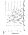
- FIG. 7 the temperature dependence of Emission spectrum of the semiconductor laser device shown. This was a multi-layer structure with a Meander-shaped Schuwiderstandsbahn, such as Cu, one Resistance from 65 ⁇ at room temperature to electrical Heating the semiconductor laser device used.
- FIG. 7 Plotted in FIG. 7 is the optical intensity of the radiation generated by the semiconductor laser component in arbitrary units and in dependence on the wavelength of the radiation generated by the semiconductor laser component in nm.
- the semiconductor laser component is in particular for generating infrared radiation, such as a wavelength larger or larger equal to 900 nm, formed.
- different heating voltages were applied to the heating resistor track.
- the following heating voltages correspond to the following emission distribution curves of the component: Heating voltage in V Curve 0 100 2 102 4 104 5 105 6 106 7 107 8th 108 9 109 10 110
- FIG. 8 shows the temperature dependence of the resistance R of a heating resistor layer of Cu in a multi-layer structure in ohms as a function of the heating power P_h in watts.
- the resistance is about 65 ⁇ .
- the resistance R was determined from the heating voltage and the measured heating current. The courses of resistance obtained in these different ways are in good approximation.
- FIG. 9 shows a comparison of the temperature determination of the operating temperature of the semiconductor laser component heated with the heating power P_h by means of a heating resistor layer integrated in the carrier via the known temperature dependence of the peak wavelength and via a 1 k ⁇ NTC resistor as the temperature sensor.
- Plotted is the temperature change .DELTA.T compared to the room temperature T N as a function of the heating power.
- the data points 113 of the operating temperature were determined from the temperature dependence of the peak wavelength, which changes approximately 0.30 nm per K for an infrared emitting semiconductor laser device.
- the temperature T of the temperature sensor was measured over the measured temperature dependent resistance R (T), which is T over the relationship linked, determined.
- B 3263 1 / K
- R N 1 k ⁇
- T N 298 K.
- the temperature of the semiconductor laser component determined via the peak wavelength substantially coincides with the temperature of the temperature sensor, so that the operating temperature of the semiconductor laser component can be reliably determined via the temperature sensor.
- the decrease of optical peak power with increasing Temperature is therefore about -0.25 W / K.
- FIG. 11 shows a comparison of the temperature change ⁇ T of FIG Semiconductor laser device in Kelvin depending on the Heating power P_h in watts for one in several ways heated semiconductor laser device shown.
- the semiconductor laser device by means of two discrete heating resistors (according to FIG. 2 with 56 ⁇ each), for the curve 117 by means of an integrated in the carrier Schuwiderstandstik (according to Figure 6 with a resistor of 65 ⁇ at room temperature) and curve 118 by means of two between the semiconductor laser device and the carrier arranged heating resistors (according to Figure 4, each with 56 ⁇ ).
- an im Subcarrier simulates integrated heating resistance range.
- a heating resistor region integrated in the intermediate carrier is therefore particularly suitable for heating the semiconductor component, but is also associated with comparatively high outlay and costs.
- heating via a heating resistor layer is more cost-effective, with discrete heating resistances being particularly easy to handle and cost-effective.
- surface mount SMD heater resistors can be particularly easily integrated into the device.
- FIG. 12 shows a comparison of the temperature determination of the operating temperature of the semiconductor laser component heated by the heating power P_h by means of two heating resistors between the carrier and the semiconductor laser component via the known temperature dependence of the peak wavelength on the one hand and via a 1 k ⁇ NTC resistor arranged at a distance from the semiconductor component (see FIGS Versions of Figure 9) as a temperature sensor on the other.
- the temperature change ⁇ T is plotted against the room temperature as a function of the heat output.
- the curve 119 of the temperature change determined by the NTC resistance deviates considerably from the curve 120 which was determined via the peak wavelength.
- the temperature change determined by the peak wavelength is greater than the temperature change detected by the NTC resistor.
- the temperature determined by means of the peak wavelength corresponds approximately to the operating temperature and the temperature determined by means of the NTC resistor corresponds more closely to the ambient temperature.
- a closely adjacent arrangement of the heating resistors to the semiconductor laser device thus results in an extremely efficient heating.
- FIG. 13 shows the thermal transient response of the Semiconductor laser device for the above three Heating variants based on the dependence of on 1 normalized operating temperature T_b of the semiconductor laser device in arbitrary units from the heating time T_h of the semiconductor laser device in seconds.
- the curve 121 corresponds to the variant according to FIG. 4 with two Heating resistors connected between the semiconductor laser device and the carrier are arranged, the curve 122 of the variant with the heating resistor layer integrated in the carrier according to Figure 6 and the curve 123 of the variant with the two discrete Heating resistors according to Figure 2.
- the operating temperature achieves the maximum value for all three variants about 100 s, which is reaching the thermal Balance between the heating element, the environment and the Semiconductor laser device corresponds.
- the thermal time constant ⁇ after which the Operating temperature of the semiconductor laser device half their maximum temperature is, lies for the three variants between, respectively, about 20 s and about 25 s.
- the invention is not by the description based on the Embodiments limited. Rather, the includes Invention every new feature as well as every combination of Characteristics, which in particular any combination of features in the patent claims, even if this feature or that combination itself is not explicit in the Claims or embodiments is given.
Landscapes
- Physics & Mathematics (AREA)
- Condensed Matter Physics & Semiconductors (AREA)
- General Physics & Mathematics (AREA)
- Electromagnetism (AREA)
- Optics & Photonics (AREA)
- Semiconductor Lasers (AREA)
- Led Devices (AREA)
- Semiconductor Integrated Circuits (AREA)
Abstract
Description
Die Erfindung betrifft eine Vorrichtung mit einem strahlungsemittierenden Halbleiterbauelement und ein Verfahren zur Temperaturstabilisierung eines strahlungsemittierenden Halbleiterbauelements.The invention relates to a device with a radiation-emitting semiconductor device and a Method for temperature stabilization of a radiation-emitting semiconductor device.
Die Peakwellenlänge der von einer Laserdiode einer derartigen Vorrichtung emittierten Strahlung wird bekanntlich von der Betriebstemperatur des Halbleiterbauelements beeinflusst, die von der Umgebungstemperatur des Halbleiterbauelements abhängt. Änderungen in der Umgebungstemperatur können somit zu Schwankungen der Peakwellenlänge des Halbleiterbauelements führen. Derartige Schwankungen der Peakwellenlänge sind jedoch oftmals unerwünscht. Die Peakwellenlänge eines Laserdiodenbauelements wird deshalb des öfteren durch zusätzliche Maßnahmen stabilisiert. Bei kantenemittierenden Laserdioden beispielsweise kann ein spektraler Filter, etwa ein Bragg-Gitter, wie bei DFB- (Distributed Feedback) oder DBR-Lasern (Distributed Bragg Reflector), zur Wellenlängenstabilisierung in das Bauelement integriert werden. Derartige Laser sind jedoch meist nur für vergleichsweise geringe optische Ausgangsleistungen geeignet. Bei Halbleiterlaser-Bauelementen mit externem Resonator, etwa mit vertikaler Emissionsrichtung (z.B. VECSEL: Vertical External Cavity Surface Emitting Laser) kann zur Wellenlängenstabilisierung ein Beugungsgitter oder eine Bragg-Faser als Filterelement im Resonator angeordnet werden. Hierdurch können resonatorinterne Verluste gezielt so erhöht werden, dass die Peakwellenlänge des Bauelements vergleichsweise stabil ist. Weiterhin kann eine Laserdiode zur Wellenlängenstabilisierung entsprechend gekühlt werden, z. B. über ein Peltier-Element oder Kühlwasser.The peak wavelength of the radiation emitted by a laser diode of such a device is known to be influenced by the operating temperature of the semiconductor device, which depends on the ambient temperature of the semiconductor device. Changes in the ambient temperature can thus lead to fluctuations in the peak wavelength of the semiconductor device. However, such fluctuations in the peak wavelength are often undesirable. The peak wavelength of a laser diode device is therefore often stabilized by additional measures. In edge-emitting laser diode, for example, a spectral filter may, for example a Bragg grating, as in the DFB (D istributed F eed b ack) or DBR lasers (D istributed B ragg R eflector) are integrated for wavelength stabilization in the device. However, such lasers are usually only suitable for comparatively low optical output powers. In semiconductor laser devices with external cavity, such as with a vertical emission direction (eg VECSEL: V ertical E Xternal C avity S urface E mitting L aser) for wavelength stabilization, a diffraction grating or a Bragg fiber as a filter element can be arranged in the resonator. As a result, resonator-internal losses can be selectively increased so that the peak wavelength of the device is comparatively stable. Furthermore, a laser diode for wavelength stabilization can be cooled accordingly, for. B. via a Peltier element or cooling water.
Die vorstehenden Maßnahmen zur Wellenlängenstabilisierung sind jedoch vergleichsweise aufwändig und/oder kostenintensiv. Ein spektraler Filter etwa muss bei der Herstellung in eine Laserdiodenstruktur integriert werden, ein Beugungsgitter oder eine Bragg-Faser im Resonator angeordnet und justiert werden. Peltier-Elemente sind weiterhin vergleichsweise kostenintensiv, und Kühlwasserkreisläufe, die gewöhnlich einen hohen Platzbedarf aufweisen, sind neben den hohen Kosten auch vergleichsweise aufwändig zu realisieren.The above measures for wavelength stabilization However, they are comparatively expensive and / or expensive. A spectral filter, for example, must be at Manufacturing be integrated into a laser diode structure, a diffraction grating or a Bragg fiber in the resonator be arranged and adjusted. Peltier elements are still comparatively expensive, and Cooling water circuits, which usually take up a lot of space have, in addition to the high cost and comparatively complex to realize.
Aufgabe der vorliegenden Erfindung ist es, eine Vorrichtung mit einem strahlungsemittierenden Halbleiterbauelement anzugeben, dessen Peakwellenlänge vereinfacht stabilisierbar ist. Zudem soll die Vorrichtung kostengünstig verwirklichbar und über einen weiten Umgebungstemperaturbereich zuverlässig mit stabilisierter Peakwellenlänge einsetzbar sein. Weiterhin ist es eine Aufgabe der Erfindung, ein vereinfachtes Verfahren zur Wellenlängenstabilisierung eines strahlungsemittierenden Halbleiterbauelements anzugeben.The object of the present invention is a device with a radiation-emitting semiconductor component specify whose peak wavelength easily stabilized is. In addition, the device should cost feasible and reliable over a wide ambient temperature range be used with stabilized peak wavelength. Farther It is an object of the invention, a simplified Method for wavelength stabilization of a to specify radiation-emitting semiconductor device.
Diese Aufgabe wird erfindungsgemäß durch eine Vorrichtung mit
den Merkmalen des Patentanspruchs 1 und ein Verfahren nach
Patentanspruch 26 gelöst. Vorteilhafte Weiterbildungen sind
Gegenstand der abhängigen Patentansprüche.This object is achieved by a device with
the features of
Eine erfindungsgemäße Vorrichtung umfasst mindestens ein strahlungsemittierendes Halbleiterbauelement, wobei dem Halbleiterbauelement mindestens ein elektrisches Heizelement zugeordnet ist, das zum Heizen des Halbleiterbauelements ausgebildet ist.A device according to the invention comprises at least one radiation-emitting semiconductor device, wherein the Semiconductor device at least one electric heating element associated with that for heating the semiconductor device is trained.
Durch Heizen des Halbleiterbauelements mittels des Heizelements kann die Änderung der Betriebstemperatur des Halbleiterbauelements gegenüber der Änderung der Umgebungstemperatur über einen vorgegebenen Umgebungstemperaturbereich, in dem das Halbleiterbauelement zum Betrieb vorgesehen ist, verringert werden. Die Betriebstemperatur des Halbleiterbauelements kann so auf einen Betriebstemperaturbereich stabilisiert werden, der vom vorgegebenen Umgebungstemperaturbereich derart vollständig überdeckt wird, dass der Umgebungstemperaturbereich Temperaturen aufweist, die außerhalb des Betriebstemperaturbereichs des temperaturstabilisierten Halbleiterbauelements liegen. Schwankungen in der Betriebstemperatur des Halbleiterbauelements können so verringert werden, wodurch aufgrund der Temperaturabhängigkeit der Peakwellenlänge einer vom Halbleiterbauelement erzeugten Strahlung die Schwankung der Peakwellenlänge im Betrieb des Halbleiterbauelements über den vorgegebenen Umgebungstemperaturbereich verringert wird.By heating the semiconductor device by means of Heating element can change the operating temperature of the Semiconductor device against the change of Ambient temperature above a given Ambient temperature range in which the semiconductor device is intended to operate, can be reduced. The Operating temperature of the semiconductor device can be so on an operating temperature range stabilized by the predetermined ambient temperature range so completely is covered that the ambient temperature range Temperatures outside the Operating temperature range of the temperature-stabilized Semiconductor device lie. Fluctuations in the Operating temperature of the semiconductor device can so be reduced, which due to the Temperature dependence of the peak wavelength of a Semiconductor device generated radiation, the variation of Peak wavelength during operation of the semiconductor device over the predetermined ambient temperature range is reduced.
Auf aufwändige herzustellende und/oder kostenintensive, im Halbleiterbauelement integrierte spektrale Filter oder justageaufwändige externe Filterelemente kann so ebenso wie auf kostenintensive Kühlung vorteilhaft verzichtet werden. Insbesondere kann das elektrische Heizelement als externes, außerhalb des Halbleiterbauelements angeordnetes, Heizelement ausgeführt sein. Ein elektrisches Heizelement erleichtert weiterhin mit Vorteil die Heizungssteuerung, etwa aufgrund einer vereinfachten Montage des Heizelements in der Vorrichtung.On expensive to produce and / or costly, in Semiconductor device integrated spectral filters or Adjustable external filter elements can as well as Advantageously dispensed with costly cooling. In particular, the electrical heating element can be used as an external, arranged outside the semiconductor device, heating element be executed. An electric heating element facilitates continue with advantage the heating control, about due a simplified installation of the heating element in the Contraption.
Halbleiterbauelemente für eine derartige Vorrichtung können somit mit Vorteil in einem kostengünstigen Standardprozess gefertigt werden und die Peakwellenlänge kann für gleichartig gefertigte Halbleiterbauelemente individuell über das jeweils zugeordnete Heizelement stabilisiert werden.Semiconductor devices for such a device can thus with advantage in a cost-effective standard process can be made and the peak wavelength can be similar manufactured semiconductor components individually on each associated heating element to be stabilized.
Es sei angemerkt, dass im Rahmen der vorliegenden Anmeldung der Begriff Umgebungstemperatur bzw. It should be noted that in the context of the present application the term ambient temperature or
Umgebungstemperaturbereich teilweise stellvertretend für den Begriff Betriebstemperatur bzw. Betriebstemperaturbereich eines nicht temperaturstabilisierten, insbesondere ungeheizten, Halbleiterbauelements verwendet wird. Die Betriebstemperatur eines nicht temperaturstabilisierten Halbleiterbauelements unterscheidet sich aufgrund der im Betrieb anfallenden Wärme zwar in der Regel von der Umgebungstemperatur, kann jedoch maßgeblich von dieser beeinflusst werden. Die Umgebungstemperatur stellt jedenfalls eine untere Grenze für die Betriebstemperatur eines nicht temperaturstabilisierten Halbleiterbauelements dar, falls die Verlustwärme im Betrieb des Halbleiterbauelements, etwa aufgrund eines Betriebs mit geringer Leistung, vernachlässigbar ist und auf zusätzliche Kühlmaßnahmen verzichtet wird. Bei der Erfindung dagegen kann die Betriebstemperatur des Halbleiterbauelements durch elektrische Heizung des Bauelements über der Umgebungstemperatur gehalten werden, so dass die Umgebungstemperatur keine untere Grenze für die Betriebstemperatur darstellt.Ambient temperature range partly representative of the Term operating temperature or operating temperature range a non-temperature-stabilized, in particular unheated, semiconductor device is used. The Operating temperature of a non-temperature-stabilized Semiconductor device differs due to the Operation accumulating heat, although usually from the Ambient temperature, however, can be significantly affected by this to be influenced. The ambient temperature is in any case a lower limit for the operating temperature of a not temperature-stabilized semiconductor device, if the Loss heat in the operation of the semiconductor device, such as due to low power operation, is negligible and on additional cooling measures is waived. In contrast, in the invention, the Operating temperature of the semiconductor device by electrical heating of the device over the Be kept at ambient temperature, so that the Ambient temperature no lower limit for the Operating temperature represents.
In einem erfindungsgemäßen Verfahren zur Temperaturstabilisierung der Betriebstemperatur eines strahlungsemittierenden Halbleiterbauelements, insbesondere eines Bauelements der Vorrichtung, ist dem Halbleiterbauelement ein elektrisches Heizelement zugeordnet, mittels dem das Halbleiterbauelement beim Unterschreiten eines vorgegebenen Sollwerts der Betriebstemperatur des Halbleiterbauelements geheizt wird. Hierdurch kann, wie bereits oben erwähnt, die Betriebstemperatur des Halbleiterbauelements in einem Betriebstemperaturbereich gehalten werden, der gegenüber dem vorgegebenen Umgebungstemperaturbereich als Betriebstemperaturbereich geschmälert ist.In a method according to the invention for Temperature stabilization of the operating temperature of a radiation-emitting semiconductor component, in particular a device of the device, is the Semiconductor device associated with an electric heating element, by means of which the semiconductor device falls below a predetermined setpoint of the operating temperature of the Semiconductor device is heated. This can, as already mentioned above, the operating temperature of the Semiconductor device in an operating temperature range to be held, which is opposite to the given Ambient temperature range as operating temperature range is diminished.
In einer bevorzugten Ausgestaltung wird beim Überschreiten des vorgegebenen Sollwerts der Betriebstemperatur des Halbleiterbauelements die Heizleistung des Heizelements reduziert oder das Heizelement wird ausgeschaltet. Übermäßiges Heizen des Halbleiterbauelements und die Gefahr einer Schädigung des überheizten Halbleiterbauelements wird so verringert.In a preferred embodiment, when crossing the predetermined reference value of the operating temperature of Semiconductor device, the heating power of the heating element reduced or the heating element is switched off. Excessive heating of the semiconductor device and the danger damage to the overheated semiconductor device is so reduced.
In einer weiteren bevorzugten Ausgestaltung ist das Halbleiterbauelement zur Erzeugung von Strahlung einer Peakwellenlänge ausgebildet, die über den vorgegebenen Umgebungstemperaturbereich, in dem das Halbleiterbauelement zum Betrieb vorgesehen ist, in einem Schwankungsbereich variiert. Der Schwankungsbereich muss nicht notwendigerweise zusammenhängend sein, vielmehr kann auch eine sprunghafte Änderung der Peakwellenlänge auftreten.In a further preferred embodiment that is Semiconductor device for generating radiation of a Peak wavelength formed over the given Ambient temperature range in which the semiconductor device intended for operation, in a fluctuation range varied. The fluctuation range does not necessarily have to can be connected, but can also be a leap Change the peak wavelength occur.
Gegenüber dem Schwankungsbereich des unbeheizten Halbleiterbauelements mit einer maßgeblich von der Umgebungstemperatur beeinflussten Betriebstemperatur kann der Schwankungsbereich der Peakwellenlänge des beheizten Halbleiterbauelements geschmälert sein.Opposite the fluctuation range of the unheated Semiconductor device with a significant of the Ambient temperature influenced operating temperature can the Fluctuation range of the peak wavelength of the heated Be narrowed semiconductor device.
Insbesondere kann eine Breite des Schwankungsbereichs der
Peakwellenlänge über Heizen des Halbleiterbauelements mittels
des Heizelements von einer ersten Breite des ungeheizten
Halbleiterbauelements auf eine zweite Breite des geheizten
Halbleiterbauelements reduziert werden, wobei die zweite
Breite kleiner als die erste Breite ist. Der
Schwankungsbereich der ersten Breite überdeckt denjenigen der
zweiten Breite vorzugsweise vollständig. Der
Schwankungsbereich kann derart geschmälert werden, dass die
zweite Breite 60 %, vorzugsweise 55 %, oder weniger der
ersten Breite beträgt.In particular, a width of the fluctuation range of
Peak wavelength over heating of the semiconductor device by means of
of the heating element of a first width of the unheated
Semiconductor device to a second width of the heated
Semiconductor device can be reduced, the second
Width is smaller than the first width. Of the
Variation range of the first width covers those of
second width preferably completely. Of the
The fluctuation range can be narrowed down so that the
Als Breite wird hierbei der Betrag der Differenz der kleinsten und der größten Peakwellenlänge über den Betriebstemperaturbereich des Halbleiterbauelements angesehen. Die Breite des Schwankungsintervalls des ungeheizten Halbleiterbauelements ist zumindest ungefähr durch die Differenz der maximalen und der minimalen Peakwellenlänge bestimmt, die vom Halbleiterbauelement emittierte Strahlung für eine Betriebstemperatur des Halbleiterbauelements über den gesamten Umgebungstemperaturbereich annimmt. Entsprechendes gilt für die Breite des Schwankungsintervalls des temperaturstabilisierten, geheizten Halbleiterbauelements.The width is the amount of the difference smallest and the largest peak wavelength over the Operating temperature range of the semiconductor device considered. The width of the fluctuation interval of the unheated semiconductor device is at least about by the difference of the maximum and the minimum Peak wavelength determined by the semiconductor device emitted radiation for an operating temperature of Semiconductor device over the entire Ambient temperature range assumes. The same applies to the width of the fluctuation interval of the temperature-stabilized, heated semiconductor device.
Die Schwankung der Peakwellenlänge des Halbleiterbauelements kann somit insgesamt mittels gezielter Temperaturstabilisierung über das elektrische Heizelement vorteilhaft verringert werden. In der Folge wird die Peakwellenlänge des Halbleiterbauelements stabilisiert.The fluctuation of the peak wavelength of the semiconductor device can thus overall by means of targeted Temperature stabilization via the electric heating element be reduced advantageous. As a result, the Peak wavelength of the semiconductor device stabilized.
Bevorzugt ist das Halbleiterbauelement zum Betrieb in einem Umgebungstemperaturbereich, der Temperaturen kleiner und größer 0°C, insbesondere von -40°C bis 85°C, umfasst, vorgesehen. Mittels der elektrischen Heizung kann erreicht werden, dass die Betriebstemperatur des Halbleiterbauelements bei Temperaturen, insbesondere durchweg, im Bereich größer 0°C, insbesondere im Bereich von 20°C bis 85°C, liegt. Ein Betriebstemperaturfenster des Halbleiterbauelements kann von einem ersten Fenster des ungeheizten, etwa einer Breite von 125 K, auf ein zweites Fenster des geheizten Halbleiterbauelements, etwa einer Breite von 65 K, geschmälert sein. Derartige Temperaturen können bei Außenanwendungen des Halbleiterbauelements, etwa in einer Vorrichtung im Fahrzeugbereich, auftreten.The semiconductor component is preferred for operation in one Ambient temperature range, the temperatures smaller and greater than 0 ° C, in particular from -40 ° C to 85 ° C, intended. By means of electric heating can be achieved be that the operating temperature of the semiconductor device at temperatures, especially consistently, in the area larger 0 ° C, in particular in the range of 20 ° C to 85 ° C, is located. One Operating temperature window of the semiconductor device can of a first window of the unheated, about a width of 125 K, on a second window of the heated Semiconductor device, about a width of 65 K, be diminished. Such temperatures can at External applications of the semiconductor device, such as in a Device in the vehicle area, occur.
In einer weiteren bevorzugten Ausgestaltung ist dem Halbleiterbauelement ein, vorzugsweise elektrischer, Temperatursensor zur Überwachung der Betriebstemperatur des Halbleiterbauelements zugeordnet. Bevorzugt kann der Betrieb des elektrischen Heizelements mittels des Temperatursensors, etwa mittels eines im Temperatursensor erzeugten oder eines am Temperatursensor ermittelten Signals, gesteuert werden. In a further preferred embodiment is the Semiconductor device on, preferably electrical, Temperature sensor for monitoring the operating temperature of the Assigned semiconductor device. Preferably, the operation the electric heating element by means of the temperature sensor, for example by means of a generated in the temperature sensor or a be detected at the temperature sensor signal.
Ein NTC-Element mit negativem Temperaturkoeffizienten (Negative Temperature Coefficient), etwa ein NTC-Thermistor (Thermistor: Ein temperaturabhängiger Widerstand), ist als Temperatursensor besonders geeignet.An NTC element having a negative temperature coefficient (egative N T emperature C oefficient), such as a NTC-thermistor (thermistor: a temperature-dependent resistor), is particularly suitable as a temperature sensor.
Über den Temperatursensor wird vorzugsweise die Betriebstemperatur des Halbleiterbauelements ermittelt. Beim Unterschreiten des vorgegebenen Sollwerts kann ein Heizen des Halbleiterbauelements mittels des Heizelements veranlasst werden. Wird der Sollwert überschritten wird zweckmäßigerweise die Heizleistung reduziert oder das Heizelement ausgeschaltet. Liegt die Betriebstemperatur bereits über dem Sollwert, so wird das Heizelement bevorzugt nicht betrieben. Diese Heizungssteuerung kann gegebenenfalls über ein externes Auswerteelement erfolgen, das die mittels des Temperatursensors bestimmte Betriebstemperatur des Halbleiterbauelements überwacht und mit dem Sollwert vergleicht.About the temperature sensor is preferably the Operating temperature of the semiconductor device determined. At the Falling below the predetermined setpoint, a heating of the Semiconductor device caused by the heating element become. If the setpoint is exceeded expediently reduces the heating power or the Heating element switched off. Is the operating temperature already above the setpoint, the heating element is preferred not operated. This heating control can if necessary take place via an external evaluation, the means of the temperature sensor certain operating temperature of the Semiconductor device monitored and with the setpoint compares.
In einer weiteren bevorzugten Ausgestaltung ist dem Halbleiterbauelement ein Detektorelement zur Detektion der vom Halbleiterbauelement emittierten Strahlung zugeordnet, das zur Detektion von Strahlung mit Wellenlängen in einem vorgegebenen, vorzugsweise zusammenhängenden, Detektionsbereich ausgebildet ist. Derartige Detektorelemente sind häufig in einer Sensorvorrichtung mit einem Halbleiterbauelement als Sender und dem Detektor als Empfänger vorgesehen, wobei der Detektionsbereich zur Vermeidung unerwünschter Umgebungslichteinflüsse, welche oftmals ein Rauschen des Detektorsignals verursachen, vorzugsweise möglichst schmal ist.In a further preferred embodiment is the Semiconductor device, a detector element for detecting the associated with radiation emitted by the semiconductor device, that for the detection of radiation with wavelengths in one predetermined, preferably contiguous, Detection area is formed. Such detector elements are common in a sensor device with one Semiconductor device as a transmitter and the detector as Receiver provided, wherein the detection area for Avoidance of unwanted ambient light influences, which often cause a noise of the detector signal, preferably as narrow as possible.
Der Detektionsbereich in einer herkömmlichen derartigen Vorrichtung ist oft so gewählt, dass er den Schwankungsbereich der Peakwellenlänge über den Umgebungstemperaturbereich umfasst, um eine Detektion der Strahlung des ungeheizten Halbleiterbauelements mit einer Betriebstemperatur über im wesentlichen den gesamten Umgebungstemperaturbereich zu sichern. Bei der Erfindung dagegen kann der Detektionsbereich derart ausgebildet sein, dass der Schwankungsbereich der Peakwellenlänge des ungeheizten Halbleiterbauelements Wellenlängen außerhalb des Detektionsbereichs aufweist und der Detektionsbereich den Schwankungsbereich der Peakwellenlänge des temperaturstabilisierten Halbleiterbauelements, vorzugsweise vollständig, überdeckt. Das Detektorelement kann somit in einer Vorrichtung mit einem temperaturstabilisierten Halbleiterbauelement gegenüber einer Vorrichtung mit einem nicht temperaturstabilisierten Halbleiterbauelement mit einem schmalbandigeren Detektionsbereich ausgeführt sein und Umgebungslichteinflüsse auf ein Detektorsignal können vorteilhaft verringert werden. Als Strahlungsdetektoren eignen sich beispielsweise besonders Fotodioden, etwa PIN- oder Lawinen-Fotodioden (APD: Avalanche Photodiode), vorzugsweise auf Si basierend, deren Detektionsbereich durch entsprechende Filter an das Halbleiterbauelement bzw. den Schwankungsbereich der Peakwellenlänge des geheizten Halbleiterbauelements angepasst ist.The detection area in a conventional such Device is often chosen so that he Range of fluctuation of the peak wavelength over the Ambient temperature range includes a detection of the Radiation of the unheated semiconductor device with a Operating temperature over substantially the entire Ambient temperature range to secure. In the invention on the other hand, the detection area can be designed in such a way that the fluctuation range of the peak wavelength of the unheated semiconductor device wavelengths outside the Detection area has and the detection area the Fluctuation range of the peak wavelength of the temperature-stabilized semiconductor device, preferably completely, covered. The detector element can thus in a device with a temperature-stabilized Semiconductor device compared to a device with a not temperature-stabilized semiconductor device having a be executed narrowband detection range and Ambient light effects on a detector signal can be reduced advantageous. As radiation detectors For example, photodiodes, such as PIN or avalanche photodiodes (APD: avalanche photodiode), preferably based on Si, their detection range by corresponding filter to the semiconductor device or the Fluctuation range of the peak wavelength of the heated Semiconductor device is adapted.
In einer weiteren bevorzugten Ausgestaltung ist das Halbleiterbauelement als Halbleiterlaser-Bauelement, insbesondere Hochleistungslaser-Bauelement, ausgeführt. Aufgrund der vergleichsweise schmalbandigen Emissionsspektren von Halbleiterlaser-Bauelementen macht sich die Temperaturabhängigkeit der Peakwellenlänge bei Halbleiterlaser-Bauelementen oft besonders stark bemerkbar. Das Halbleiterlaser-Bauelement kann beispielsweise als kantenemittierende Laserdiode oder als Laserdiodenbarren ausgebildet sein. Ein Laserdiodenbarren umfasst hierbei eine Mehrzahl von Laserdiodenstrukturen (Laserdiodenkanäle), die monolithisch integriert und auf einem gemeinsamen Substrat angeordnet sind. Weiterhin kann das Halbleiterbauelement als oberflächenemittierendes Halbleiterbauelement, insbesondere Halbleiterlaser-Bauelement, ausgeführt sein. Beispielsweise kann das oberflächenemittierende Halbleiterbauelement als vertikal emittierendes Halbleiterlaser-Bauelement mit internem Resonator (VCSEL: Vertical Surface Emitting Laser) oder mit externem Resonator (VECSEL) ausgebildet sein. Bevorzugt ist das Halbleiterlaser-Bauelement zum gepulsten Betrieb, insbesondere in einer Sensorvorrichtung mit einem dem Bauelement zugeordneten Detektorelement, vorgesehen.In a further preferred refinement, the semiconductor component is designed as a semiconductor laser component, in particular a high-power laser component. Due to the comparatively narrow-band emission spectra of semiconductor laser components, the temperature dependence of the peak wavelength often makes itself particularly noticeable in semiconductor laser components. The semiconductor laser component can be designed, for example, as an edge-emitting laser diode or as a laser diode bar. A laser diode bar in this case comprises a plurality of laser diode structures (laser diode channels) which are monolithically integrated and arranged on a common substrate. Furthermore, the semiconductor component can be embodied as a surface-emitting semiconductor component, in particular a semiconductor laser component. For example, the surface-emitting semiconductor component can be used as vertically emitting semiconductor laser device with an internal resonator (VCSEL: V ertical S urface E mitting L aser) or be formed with an external resonator (VECSEL). The semiconductor laser component is preferably provided for pulsed operation, in particular in a sensor device with a detector element associated with the component.
In einer weiteren bevorzugten Ausgestaltung ist das Halbleiterbauelement auf einem Träger, etwa einer Leiterplatte, angeordnet. Vorzugsweise ist das Heizelement ebenfalls auf dem Träger angeordnet. Hierdurch wird, insbesondere über eine vergleichsweise nah benachbarte Anordnung des Heizelements und des Halbleiterbauelements, eine effiziente Beheizung des Halbleiterbauelements erleichtert. Weiterhin ist das Heizelement und/oder gegebenenfalls der Temperatursensor, bevorzugt oberflächenmontierbar (SMD: Surface Mountable Device) ausgebildet, wodurch eine Montage des Heizelements auf dem Träger und eine kompakte Ausbildung der Vorrichtung erleichtert werden.In a further preferred embodiment that is Semiconductor device on a support, such as a PCB, arranged. Preferably, the heating element also arranged on the carrier. This will especially over a comparatively close neighbor Arrangement of the heating element and of the semiconductor component, an efficient heating of the semiconductor device facilitated. Furthermore, the heating element and / or optionally the temperature sensor, preferred surface mountable (SMD: Surface Mountable Device) formed, whereby an assembly of the heating element on the Carrier and a compact design of the device be relieved.
In einer weiteren bevorzugten Ausgestaltung ist das Heizelement als Heizwiderstand ausgeführt. Durch Anlegen einer Spannung an den Heizwiderstand kann über Stromfluss durch den Heizwiderstand dementsprechend Wärme erzeugt und das Halbleiterbauelement beheizt werden.In a further preferred embodiment that is Heating element designed as a heating resistor. By applying A voltage across the heating resistor may be due to current flow heat generated by the heating resistor accordingly and the semiconductor device are heated.
In einer weiteren bevorzugten Ausgestaltung ist das Heizelement im Träger des Halbleiterbauelements integriert. Der Träger kann somit schon mit integriertem Heizelement bereitgestellt werden, wodurch auf eine zusätzliche Anordnung eines separaten Heizelements auf dem Träger verzichtet werden kann. Bevorzugt weist der Träger hierzu eine Mehrschichtstruktur auf und das Heizelement ist als Heizwiderstandsschicht in der Mehrschichtstruktur integriert. Besonders geeignet ist hierzu eine Mehrschicht-Leiterplatte, die eine, vorzugsweise in eine oder mehrere, etwa meanderförmig verlaufende, Heizwiderstandsbahn(en) strukturierte und/oder Cu enthaltende, Heizwiderstandsschicht aufweist.In a further preferred embodiment that is Heating element integrated in the carrier of the semiconductor device. The carrier can thus already with integrated heating element be provided, resulting in an additional arrangement dispensed with a separate heating element on the carrier can. For this purpose, the carrier preferably has one Multi-layer structure and the heating element is as Heizwiderstandsschicht integrated in the multi-layer structure. Particularly suitable for this purpose is a multilayer printed circuit board, one, preferably one or more, such as meandering, Heizwiderstandsbahn (s) structured and / or Cu-containing, Heizwiderstandsschicht having.
In einer weiteren bevorzugten Ausgestaltung ist das Heizelement zwischen dem Träger und dem Halbleiterbauelement oder das Halbleiterbauelement ist auf dem Heizelement angeordnet. Durch eine derartige Nähe von Heizelement und Halbleiterbauelement wird eine effiziente, flächige Beheizung des Halbleiterbauelements erleichtert.In a further preferred embodiment that is Heating element between the carrier and the semiconductor device or the semiconductor device is on the heating element arranged. Due to such proximity of heating element and Semiconductor device becomes an efficient, areal heating the semiconductor device facilitated.
In einer weiteren bevorzugten Ausgestaltung der Erfindung ist zwischen dem Träger und dem Halbleiterbauelement ein Zwischenträger (Submount) angeordnet. Mittels eines derartigen Zwischenträgers kann die Gefahr einer Abschattung der vom Halbleiterbauelement emittierten Strahlung durch eine Kante des Trägers verringert werden.In a further preferred embodiment of the invention between the carrier and the semiconductor device Submount arranged. By means of a such intermediate carrier may increase the risk of shading the radiation emitted by the semiconductor device by a Edge of the carrier can be reduced.
In einer vorteilhaften Weiterbildung ist der Zwischenträger als Heizelement ausgebildet oder der Zwischenträger enthält das Heizelement. Hierbei ist das Heizelement vorzugsweise ein Heizwiderstandsbereich, der im Zwischenträger ausgebildet sein kann. Ein derartiger Heizwiderstandsbereich kann mittels Implantation, etwa Protonen-Implantation, in einen Bereich des Zwischenträgers realisiert sein. Vorzugsweise enthält der Zwischenträger hierzu ein Halbleitermaterial, etwa Si. Bevorzugt ist der Heizwiderstandsbereich weiterhin im Zwischenträger oberflächennah an der dem Halbleiterbauelement zugewandten Oberfläche des Zwischenträgers ausgeführt und/oder an dieser Oberfläche elektrisch anschließbar.In an advantageous development of the intermediate carrier designed as a heating element or contains the intermediate carrier the heating element. Here, the heating element is preferably a Heizwiderstandsbereich formed in the intermediate carrier can be. Such a Heizwiderstandsbereich can by means of Implantation, such as proton implantation, in one area be realized by the intermediary. Preferably, the Intermediate carrier for this purpose, a semiconductor material, such as Si. Preferably, the Heizwiderstandsbereich is still in Subcarrier near the surface of the semiconductor device facing surface of the intermediate carrier executed and / or electrically connectable to this surface.
In einer weiteren bevorzugten Ausgestaltung ist das Heizelement elektrisch von dem Halbleiterbauelement isoliert. Somit ist eine getrennte elektrische Ansteuerung von Heizelement und Halbleiterbauelement möglich. Insbesondere können das Heizelement und das Halbleiterbauelement mit Vorteil unabhängig voneinander betrieben werden.In a further preferred embodiment that is Heating element electrically isolated from the semiconductor device. Thus, a separate electrical control of Heating element and semiconductor device possible. Especially can the heating element and the semiconductor device with Advantage operated independently.
In einer weiteren bevorzugten Ausgestaltung ist das Heizelement gesondert thermisch leitend mit dem Halbleiterbauelement verbunden. Die Effizienz der Beheizung kann so erhöht werden. Hierzu kann beispielsweise ein thermischer Verbindungsleiter, etwa Cu enthaltend, vorgesehen sein, der das Halbleiterbauelement und das Heizelement thermisch leitend verbindet.In a further preferred embodiment that is Heating element separately thermally conductive with the Semiconductor device connected. The efficiency of heating can be increased. For this purpose, for example, a thermal connection conductor, containing about Cu, provided be the semiconductor device and the heating element thermally conductive connects.
In einer vorteilhaften Weiterbildung der Erfindung ist der Temperatursensor gesondert thermisch leitend mit dem Halbleiterbauelement verbunden. Aufgrund einer thermisch leitenden Verbindung kann die Temperatur effizienter überwacht werden, da die Gefahr einer Abweichung der mittels des Temperatursensors bestimmten Betriebstemperatur von einer tatsächlichen Betriebstemperatur des Halbleiterbauelements verringert wird. Zur Verbesserung der thermischen Anbindung kann beispielsweise ein weiterer thermischer Verbindungsleiter, etwa Cu enthaltend, vorgesehen sein, der das Halbleiterbauelement und den Temperatursensor thermisch leitend verbindet.In an advantageous embodiment of the invention is the Temperature sensor separately thermally conductive with the Semiconductor device connected. Due to a thermal Conductive connection can make the temperature more efficient be monitored, since the risk of a deviation of means the temperature sensor specific operating temperature of a actual operating temperature of the semiconductor device is reduced. To improve the thermal connection For example, another thermal Connecting conductor, containing about Cu be provided, the the semiconductor device and the temperature sensor thermally conductively connects.
In einer weiteren bevorzugten Ausgestaltung der Erfindung erfolgt die Heizung des Halbleiterbauelements über das Material des Trägers. Insbesondere kann die Wärmezufuhr durch ein elektrisch isolierendes Grundmaterial des Trägers erfolgen. Auf das Ausbilden gesonderter thermischer Verbindungsleiter kann so verzichtet werden.In a further preferred embodiment of the invention the heating of the semiconductor component takes place via the Material of the carrier. In particular, the heat can be through an electrically insulating base material of the carrier respectively. On the formation of separate thermal Connecting conductor can be dispensed with.
Weitere Merkmale, Vorteile und Zweckmäßigkeiten der Erfindung ergeben sich aus der Beschreibung der folgenden Ausführungsbeispiele in Verbindung mit den Figuren.Other features, advantages and advantages of the invention result from the description of the following Embodiments in conjunction with the figures.
Es zeigen:
Gleiche, gleichartige oder gleichwirkende Elemente sind in den Figuren mit den gleichen Bezugszeichen versehen.Same, similar or equivalent elements are in the figures provided with the same reference numerals.
Figur 1 zeigt ein erstes Ausführungsbeispiel einer erfindungsgemäßen Vorrichtung anhand einer schematischen Aufsicht in Figur 1A und einer schematischen Schnittansicht in Figur 1B entlang der Linie A-A.Figure 1 shows a first embodiment of a Device according to the invention with reference to a schematic Top view in Figure 1A and a schematic sectional view in Figure 1B along the line A-A.
Einem strahlungsemittierenden Halbleiterbauelement 1 der
Vorrichtung ist ein elektrisches Heizelement 2 zugeordnet,
das zum Heizen des Halbleiterbauelements ausgebildet ist. Das
Heizelement und das Halbleiterbauelement sind mit einem,
insbesondere elektrischen, Temperatursensor 3 auf einem,
insbesondere gemeinsamen, Träger 4 angeordnet. Zwischen dem
Halbleiterbauelement 1 und dem Träger 4 ist ein
Zwischenträger 6 angeordnet, der aufgrund der mittels des
Zwischenträgers gegenüber dem Träger erhöhten Anordnung des
Halbleiterbauelements die Abschattung einer vom
Halbleiterbauelement emittierten Strahlung 12 durch den
Träger 4 vermindert. A radiation-emitting
Dem Halbleiterbauelement 1 ist weiterhin ein Detektorelement
13, etwa eine PIN- oder Lawinenfotodiode, zur Detektion einer
vom Halbleiterbauelement erzeugten Strahlung 12 zugeordnet.
Das Detektorelement kann, anders als dargestellt, ebenfalls
auf dem Träger 4 angeordnet sein. Eine kompakte Ausbildung
einer derartigen Sensorvorrichtung wird so erleichtert.The
Bevorzugt ist zwischen dem Heizelement und dem
Halbleiterbauelement und/oder dem Halbleiterbauelement und
dem Temperatursensor eine gesonderte thermisch leitende
Verbindung ausgebildet. Beispielsweise ist hierzu ein erster
thermischer Verbindungsleiter 5a mit dem Heizelement 2 und
dem Halbleiterbauelement 1 und ein zweiter Verbindungsleiter
5b mit dem Halbleiterbauelement und dem Temperatursensor
thermisch leitend verbunden. Thermisch sind die
Verbindungsleiter mit Vorzug nicht unmittelbar leitend
verbunden. Beispielsweise enthalten die Verbindungsleiter 5a
und 5b ein Metall, etwa Cu.It is preferred between the heating element and the
Semiconductor device and / or the semiconductor device and
the temperature sensor a separate thermally conductive
Compound formed. For example, this is a first
Weiterhin ist der Träger bevorzugt als Leiterplatte, etwa als
PCB (PCB: Printed Circuit Board) ausgeführt. Auf:die
Darstellung von Leiterbahnen der Leiterplatte sowie
elektrischer Anschlüsse des Heizelements 2, des
Halbleiterbauelements 1 und des Temperatursensors 3 wurde der
Übersichtlichkeit halber verzichtet. Besonders bevorzugt sind
das Halbleiterbauelement, das Heizelement und der
Temperatursensor über Leiterbahnen der Leiterplatte,
insbesondere elektrisch voneinander getrennt, anschließbar
und/oder ansteuerbar. Vorzugsweise sind die thermischen
Verbindungsleiter im Träger integriert.Furthermore, the carrier is preferred as a printed circuit board, such as
PCB (PCB: Printed Circuit Board). On the
Representation of printed conductors of the printed circuit board as well
electrical connections of the
Alternativ kann jedoch auch auf die thermischen Verbindungsleiter verzichtet werden. Die Beheizung des Halbleiterbauelements erfolgt dann vorzugsweise über das Material des Trägers. Insbesondere kann die Wärmezufuhr zum Halbleiterbauelement in diesem Falle durch ein elektrisch isolierendes Grundmaterial, z.B. ein Kunststoffmaterial, des Trägers erfolgen.Alternatively, however, can also be applied to the thermal Connecting conductors are omitted. The heating of the Semiconductor device is then preferably via the Material of the carrier. In particular, the heat supply to Semiconductor device in this case by an electric insulating base material, e.g. a plastic material, the Carrier.
Das elektrische Heizelement, das Halbleiterbauelement und/oder der Temperatursensor ist bevorzugt oberflächenmontierbar ausgeführt und kann zum Beispiel auf den Träger gelötet sein. Beispielsweise ist der Temperatursensor als oberflächenmontierbarer NTC-Thermistor und/oder das elektrische Heizelement als oberflächenmontierbarer Heizwiderstand ausgeführt. Das Halbleiterbauelement ist bevorzugt ohne zusätzliches Gehäuse auf dem Träger montiert (Chip on Board).The electric heating element, the semiconductor device and / or the temperature sensor is preferred surface mountable and can, for example, on be soldered to the carrier. For example, the Temperature sensor as surface mounted NTC thermistor and / or the electric heating element as surface-mounted heating resistor executed. The Semiconductor component is preferably without additional housing mounted on the carrier (chip on board).
Eine thermisch leitende Verbindung zwischen dem elektrischen
Heizelement 2 und/oder dem Temperatursensor 3 und dem
Halbleiterbauelement 1 kann mit Vorteil mittels des
Zwischenträgers 6 erzielt werden. Hierzu ist der
Zwischenträger zweckmäßigerweise mit einer entsprechend hohen
thermischen Leitfähigkeit ausgebildet. Beispielsweise enthält
der Zwischenträger ein Halbleitermaterial, etwa Si, oder ein
Metall, wie Cu, oder eine Legierung, etwa CuWo. Derartige
Materialien können sich neben einer vergleichsweise hohen
thermischen Leitfähigkeit auch durch gute Anpassung an den
thermischen Ausdehnungskoeffizienten des
Halbleiterbauelements auszeichnen, wodurch die Gefahr
thermisch induzierter Verspannungen im Halbleiterbauelement
verringert wird.A thermally conductive connection between the
Es sei angemerkt, dass die Verbindungsleiter 5a oder 5b nicht
notwendigerweise, wie dargestellt, auf der dem
Halbleiterbauelement zugewandten Seite des Trägers angeordnet
sein müssen. Ein Verbindungsleiter kann sich auch von der
Seite des Trägers, auf der das Halbleiterbauelement
angeordnet ist, zu der dem Halbleiterbauelement
gegenüberliegenden Seite des Trägers erstrecken. Das
Heizelement und/oder der Temperatursensor können so
vereinfacht auf der dem Halbleiterbauelement
gegenüberliegenden Seite des Trägers angeordnet sein und über
einen oder eine Mehrzahl von thermische(n)
Verbindungsleiter(n) thermisch leitend mit dem
Halbleiterbauelement verbunden sein, wobei die
Betriebseffizienz der Vorrichtung trotz der derartigen
Anordnung mit Vorteil nicht maßgeblich vermindert wird.It should be noted that the
Gegebenenfalls kann eine thermisch leitende Verbindung auch über den Träger, vorzugsweise durch ein elektrisch isolierende Grundmaterial, etwa einen Kunststoff, des Trägers, erfolgen.Optionally, a thermally conductive compound also over the carrier, preferably by an electric insulating base material, such as a plastic, the Carrier, done.
Das Halbleiterbauelement 1 weist mit Vorzug eine zur
Strahlungserzeugung vorgesehene aktive Zone 9 auf, die
beispielsweise in einer auf einem Substrat 10 angeordneten
Halbleiterkörper 11 ausgebildet ist. Zweckmäßigerweise ist
das Substrat 10 aus einem Epitaxiesubstrat des
Halbleiterkörpers 11 gefertigt.The
Das Halbleiterbauelement kann beispielsweise als Halbleiterlaser-Bauelement, insbesondere zum gepulsten Betrieb, ausgeführt sein. Bevorzugt ist das Halbleiterlaser-Bauelement als kantenemittierende Laserdiode ausgeführt. Hierbei begrenzen vorzugsweise gegenüberliegende Seitenflächen 7 und 8 (Reflektorflächen) des Halbleiterlaser-Bauelements einen optischen Resonator (z.B. einen Fabry-Perot-Resonator) des Bauelements.The semiconductor component can be used, for example, as Semiconductor laser device, in particular for pulsed Operation, be executed. The semiconductor laser component is preferred designed as an edge emitting laser diode. This limit preferably opposite Side surfaces 7 and 8 (reflector surfaces) of the semiconductor laser device an optical resonator (e.g., a Fabry-Perot resonator) of the component.
Zur Strahlungserzeugung im infraroten Spektralbereich ist ein GaAs-basierender Halbleiterkörper, insbesondere auf einem GaAs Epitaxiesubstrat gewachsen, besonders geeignet.For radiation generation in the infrared spectral range is a GaAs-based semiconductor body, in particular on one GaAs epitaxial substrate grown, particularly suitable.
Ist das Halbleiterbauelement als Laserdiodenbarren
ausgeführt, so ist mit Vorzug eine Mehrzahl von
Halbleiterkörpern 11 nebeneinander auf dem gemeinsamen
Substrat 10 angeordnet. Is the semiconductor device as a laser diode bar
executed, so is preferably a plurality of
Mittels des Temperatursensors 3 wird die Betriebstemperatur
des Halbleiterbauelements derart überwacht, dass beim
Unterschreiten eines vorgegebenen Sollwerts der
Betriebstemperatur des Halbleiterbauelements das
Halbleiterbauelement mittels des elektrischen Heizelements 3
geheizt wird. Überschreitet die Betriebstemperatur den
vorgegebenen Sollwert, so wird die Heizleistung des
Heizelements reduziert oder das Heizelement ausgeschaltet.
Bevorzugt sind das Halbleiterbauelement und der
Temperatursensor unmittelbar benachbart zueinander
angeordnet, wodurch die Überwachung der Betriebstemperatur
erleichtert wird.By means of the
Zur Überwachung der Betriebstemperatur kann diese, beispielsweise über die bekannte Temperaturabhängigkeit des Widerstandes des NTC-Thermistors, über den Temperatursensor ermittelt werden und mittels einer, gegebenenfalls auf dem Träger angeordneten, Regelungsschaltung, etwa einer Transistorschaltung, die bevorzugt die ermittelte Betriebstemperatur mit dem Sollwert vergleicht, geregelt werden.To monitor the operating temperature, this can, for example, about the known temperature dependence of Resistance of the NTC thermistor, via the temperature sensor be determined and by means of one, if necessary on the Carrier arranged, control circuit, about one Transistor circuit, preferably the determined Operating temperature compared with the setpoint, regulated become.
Gegenüber einer Betriebstemperatur des Halbleiterbauelements, die über einen vorgegebenen Umgebungstemperaturbereich variiert, kann so der Schwankungsbereich der betriebstemperaturabhängigen Peakwellenlänge des Halbleiterbauelements reduziert werden, indem das Halbleiterbauelement über das elektrische Heizelement gezielt geheizt und temperaturstabilisiert wird.Opposite an operating temperature of the semiconductor device, over a given ambient temperature range varies, so can the fluctuation range of operating temperature dependent peak wavelength of Semiconductor device can be reduced by the Semiconductor device via the electric heating element targeted heated and temperature stabilized.
Der Detektionsbereich des Detektorelements kann somit mit
Vorteil schmalbandiger ausgeführt werden als ein
Schwankungsintervall der Peakwellenlänge der Strahlung 12
über dem Umgebungstemperaturbereich. Der Schwankungsbereich
der Peakwellenlänge des temperaturstabilisierten
Halbleiterbauelements wird vorzugsweise durch den
Detektionsbereich des Detektorelements vollständig überdeckt. The detection range of the detector element can thus with
Advantage narrowband running as a
Fluctuation interval of the peak wavelength of the
Dies resultiert in einem optimierten Verhältnis vom von der
Strahlung 12 erzeugten Detektorsignal zu einem, etwa durch
Umgebungslichteinflüsse hervorgerufenen, Untergrundrauschen.This results in an optimized ratio of the
Der Betriebstemperaturbereich des Halbleiterbauelements kann beispielsweise von einem vorgegebenen Umgebungstemperaturbereich mit Temperaturen von -40°C bis 85°C auf einen Betriebstemperaturbereich von 20°C bis 85°C stabilisiert werden. Aufgrund der Temperaturabhängigkeit der Peakwellenlänge wird in der Folge die Peakwellenlänge des Halbleiterbauelements stabilisiert.The operating temperature range of the semiconductor device may for example, from a given Ambient temperature range with temperatures from -40 ° C to 85 ° C to an operating temperature range of 20 ° C to 85 ° C be stabilized. Due to the temperature dependence of The peak wavelength becomes the peak wavelength of the Stabilized semiconductor device.
Die Temperaturabhängigkeit der Peakwellenlänge kann, insbesondere bei einer kantenemittierenden Laserdiode zur Erzeugung infraroter Strahlung, etwa in einem Spektralbereich von 800 bis 1000 nm, 0,3 nm/K betragen. In einem Umgebungstemperaturfenster der Breite 125 K, etwa von -40°C bis 85°C, als Betriebstemperaturbereich des ungeheizten Halbleiterbauelements bedeutet dies eine erhebliche Schwankung der Peakwellenlänge in einem Intervall einer Breite von ungefähr 38 nm, wobei mit steigender Betriebstemperatur die Peakwellenlänge wächst. Wird die Betriebstemperatur mittels elektrischer Heizung auf ein gegenüber obigem Bereich schmäleres Temperaturfenster, wie eines der Breite von 65 K, etwa von 20°C bis 85°C, stabilisiert, so kann die Breite des Schwankungsbereichs der Peakwellenlänge, etwa auf eine Breite von ungefähr 20 nm für ein Betriebstemperaturfenster von 65 K Breite, reduziert werden. Auch mit einem durch entsprechende Filter geschmälerten Detektionsbereich einer Breite von ungefähr 20 nm kann somit die vom Halbleiterbauelement erzeugte Strahlung über das Detektorelement im Betrieb des Halbleiterbauelements über den Umgebungstemperaturbereich zuverlässig detektiert werden. Umgebungslichteinflüsse auf das Detektorsignal werden durch den schmalen Detektionsbereich mit Vorteil verringert. The temperature dependence of the peak wavelength can, in particular in the case of an edge-emitting laser diode for Generation of infrared radiation, for example in a spectral range from 800 to 1000 nm, 0.3 nm / K. In one Ambient temperature window of width 125 K, about -40 ° C up to 85 ° C, as the operating temperature range of the unheated Semiconductor device, this means a considerable Fluctuation of the peak wavelength in one interval Width of about 38 nm, with increasing Operating temperature, the peak wavelength increases. Will the Operating temperature by means of electric heating on towards the above range narrower temperature window, such as one of the width of 65 K, from about 20 ° C to 85 ° C, stabilized, so can the width of the fluctuation range of the Peak wavelength, approximately to a width of about 20 nm for an operating temperature window of 65 K width, reduced become. Also with an appropriate filter Narrowed detection range of a width of about 20 nm can thus the radiation generated by the semiconductor device over the detector element during operation of the semiconductor device reliably detected over the ambient temperature range become. Ambient light influences on the detector signal Advantageously reduced by the narrow detection range.
In Figur 2 ist anhand zweier schematischer Aufsichten in
Figur 2A und 2B ein zweites Ausführungsbeispiel einer
erfindungsgemäßen Vorrichtung dargestellt. Im Wesentlichen
entspricht dieses Ausführungsbeispiel dem in Figur.1
gezeigten Ausführungsbeispiel. Im Unterschied hierzu sind
zwei elektrische oberflächenmontierbare Heizwiderstände,
beispielsweise jeweils mit einem Widerstand von 56 Ω, etwa
von der Bauform 1206 , vorgesehen, die ebenso wie der NTC-Thermistor
als Temperatursensor 3, beispielsweise ein
oberflächenmontierbarer 1kΩ-NTC Widerstand mit einem
Widerstand von 1kΩ bei Raumtemperatur (298K), auf der dem
Halbleiterbauelement 1 gegenüberliegenden Seite des Trägers 4
angeordnet sind. Das Halbleiterbauelement ist hierbei als
Laserdiodenarray (Laserdiodenbarren), insbesondere als
Pulslaserdiodenarray, ausgeführt. Weitere Einzelheiten zu
Laserdiodenbarren sind beispielsweise in dem Lehrbuch "Roland
Diehl, High Power Diode Lasers, Springer (2000)", dessen
Offenbarungsgehalt hiermit explizit durch Referenz in die
vorliegende Anmeldung aufgenommen wird, genauer beschrieben
(sh. insbesondere die dortigen Seiten 173 bis 218).FIG. 2 shows two schematic plan views in FIG
Figure 2A and 2B, a second embodiment of a
inventive device shown. Essentially
this embodiment corresponds to that in Figure 1
shown embodiment. In contrast to this are
two electrical surface-mounted heating resistors,
For example, each with a resistance of 56 Ω, about
of the type 1206, provided as well as the NTC thermistor
as a
Das Array kann derart ausgebildet sein, dass die einzelnen Laserdiodenkanäle des Arrays getrennt voneinander ansteuerbar sind oder die einzelnen Kanäle nur gemeinsam betrieben werden können. Im letzteren Fall sind die Kanäle parallel geschalten und weisen hierzu einen allen Kanälen gemeinsamen Kontakt und einen allen Kanälen gemeinsamen Gegenkontakt auf. Für eine getrennte Ansteuerung der einzelnen Kanäle kann beispielsweise ein mit allen Kanälen leitend verbundener Gegenkontakt vorgesehen sein, wobei die einzelnen Kanäle jeweils einen separaten Einzelkontakt aufweisen, über den der Stromfluss durch den jeweiligen Kanal geregelt werden kann. Die einzelnen Kanäle sind dann über den jeweiligen Einzelkontakt unabhängig voneinander betreibbar.The array can be designed such that the individual Laser diode channels of the array separately controllable or the individual channels are only operated together can. In the latter case, the channels are connected in parallel and have a common to all channels contact and a mutual contact common to all channels. For one separate control of the individual channels can For example, one with all channels conductively connected Be provided counter-contact, with the individual channels each having a separate single contact over which the Current flow through the respective channel can be controlled. The individual channels are then over the respective Single contact independently operable.
Auf jedem der beispielsweise sechzehn Laserdiodenkanäle des
Arrays sind hierbei zwei Bonddrähte zur elektrischen
Kontaktierung zugeordnet. Der Gegenpol der
Diodenkontaktierung wird mittels Bonddrähten, z.B. mit vier
Bonddrähten, hergestellt, die beispielsweise über eine auf
dem Zwischenträger 6, vorzugsweise zwischen dem
Halbleiterbauelement und dem Zwischenträger, angeordneten,
etwa metallhaltigen, Anschlussschicht, leitend mit dem
Halbleiterbauelement und elektrischen Kontakten auf dem
Träger 4, etwa Leiterbahnen eines PCB-Trägers, verbunden
sind. Die Figuren 2A und 2B zeigen Aufsichten auf den Träger
4 von der Seite des Halbleiterbauelements 1 in Figur 2A und
der diesem gegenüberliegenden Seite des Trägers 4 in Figur
1B.On each of the example sixteen laser diode channels of the
Arrays are two bonding wires for electrical purposes
Contacting assigned. The opposite pole of the
Diode contacting is accomplished by bonding wires, e.g. with four
Bonding wires, manufactured, for example, on a
the
Figur 3 zeigt eine schematische Aufsicht auf ein drittes Ausführungsbeispiel einer erfindungsgemäßen Vorrichtung in Figur 3A und eine entsprechende schematische Schnittansicht in Figur 3B. Das Ausführungsbeispiel gemäß Figur 3 entspricht im Wesentlichen dem in Figur 1 gezeigten. Im Unterschied hierzu wurde auf ein diskretes elektrisches Heizelement verzichtet. Aus Übersichtlichkeitsgründen würde ferner auf eine Darstellung des Detektorelements und der thermischen Verbindungsleiter verzichtet, die jedoch selbstverständlich auch beim dritten Ausführungsbeispiel vorgesehen sein können.FIG. 3 shows a schematic plan view of a third one Embodiment of a device according to the invention in Figure 3A and a corresponding schematic sectional view in FIG. 3B. The embodiment according to FIG. 3 corresponds essentially the one shown in FIG. In difference this was done on a discrete electrical heating element waived. For clarity, would further on a representation of the detector element and the thermal Verbindungsleiter waived, but of course can also be provided in the third embodiment.
Im Unterschied zum Ausführungsbeispiel gemäß Figur 1 ist das
Halbleiterbauelement 1 in Figur 3 auf dem Heizelement 2
angeordnet. Insbesondere kann das Heizelement zwischen dem
Träger und dem Halbleiterbauelement angeordnet sein. Das
Heizelement 2 ist bevorzugt als Heizwiderstandsbereich 20 im
Zwischenträger 6 integriert. Beispielsweise ist der
Heizwiderstandsbereich 20 mittels Protonenimplantation in
einem Bereich eines Si-Zwischenträgers hergestellt. Eine
Anordnung des Heizwiderstandsbereichs 20, wie in Figur 3B
dargestellt, direkt an der Oberfläche ist nicht zwingend
erforderlich. Der Heizwiderstandsbereich kann vielmehr auch
als vergrabener Bereich, insbesondere unterhalb der dem
Zwischenträger zugewandten Oberfläche des Zwischenträgers, im
Zwischenträger ausgebildet sein. Dementsprechend kann der
Heizwiderstandsbereich 20 von dem Halbleiterbauelement 1
und/oder dem Substrat 10 beabstandet ist.In contrast to the embodiment according to FIG. 1, this is
Bevorzugt weist der Heizwiderstandsbereich eine laterale Ausdehnung auf, die größer ist als die laterale Ausdehnung des Halbleiterbauelements, wodurch eine flächige und effiziente elektrische Beheizung des Halbleiterbauelements in verglichen mit diskreten Heizelementen unmittelbarer Nähe zum Halbleiterbauelement erleichtert wird.Preferably, the Heizwiderstandsbereich has a lateral Extension greater than the lateral extent of the semiconductor device, whereby a flat and efficient electrical heating of the semiconductor device in compared with discrete heating elements close proximity to Semiconductor device is facilitated.
Figur 4 zeigt eine schematische Aufsicht auf ein viertes
Ausführungsbeispiel einer erfindungsgemäßen Vorrichtung. Das
Halbleiterbauelement 1 ist entsprechend Figur 2 als
Pulslaserdioden-Array ausgeführt. Zwischen dem Träger 4 und
dem Halbleiterbauelement 1 sind zwei elektrische Heizelemente
2, beispielsweise in der Form zweier oberflächenmontierbarer
Heizwiderstände, die elektrisch vom Halbleiterbauelement
isoliert sind, angeordnet. Der Temperatursensor ist wie in
Figur 2 auf der dem Halbleiterbauelement gegenüberliegenden
Seite des Trägers angeordnet. Eine derartige Anordnung des
elektrischen Heizelements kann zur Simulation und für
Effizienzversuche eines im Zwischenträger integrierten
Heizelements, etwa gemäß Figur 3, herangezogen werden.FIG. 4 shows a schematic plan view of a fourth
Embodiment of a device according to the invention. The
Figur 5 zeigt eine schematische Schnittansicht eines fünften Ausführungsbeispiels einer erfindungsgemäßen Vorrichtung in Figur 5A und eine entsprechende schematische Schnittaufsicht eines Schnitts entlang der Linie A-A in Figur 5B.FIG. 5 shows a schematic sectional view of a fifth Embodiment of a device according to the invention in Figure 5A and a corresponding schematic Schnittaufsicht a section along the line A-A in Figure 5B.
Im Wesentlichen entspricht das fünfte Ausführungsbeispiel dem
dritten Ausführungsbeispiel aus Figur 3. Im Unterschied
hierzu ist das elektrische Heizelement im Träger 4
integriert. Der Träger 4 weist hierbei eine
Mehrschichtstruktur auf, die eine erste Schicht 41 auf der
dem Halbleiterbauelement 1 zugewandten Seite und eine zweite
Schicht 42 auf der dem Halbleiterbauelement abgewandten Seite
aufweist, zwischen denen eine Heizwiderstandsschicht 43
angeordnet ist.In essence, the fifth embodiment corresponds to
third embodiment of Figure 3. In difference
this is the electrical heating element in the carrier. 4
integrated. The
Die Heizwiderstandsschicht enthält beispielsweise Cu und/oder
verläuft etwa, wie in Figur 5B gezeigt, als meanderförmige
Bahn. Die Heizwiderstandsschicht 43 ist über die erste
Schicht 41 und den Zwischenträger 6 thermisch leitend mit dem
Halbleiterbauelement 1 verbunden. Bevorzugt ist die erste
Schicht 41 und/oder die zweite Schicht 42 elektrisch
isolierend ausgeführt. Die thermisch leitende Verbindung zum-Zwischenträger
oder dem Halbleiterbauelement kann
insbesondere über das elektrisch isolierende Material der
ersten Schicht 41 erfolgen.The heating resistor layer contains, for example, Cu and / or
runs approximately, as shown in Figure 5B, as a meandering
Train. The
Weiterhin kann gegebenenfalls zusätzlich oder alternativ ein
thermischer Verbindungsleiter, der sich durch die erste
Schicht 41 erstreckt und beispielsweise über den
Zwischenträger 6 mit dem Halbleiterbauelement 1 und der
Heizwiderstandsschicht, vorzugsweise direkt, thermisch
leitend verbünden ist, vorgesehen sein.Furthermore, optionally additionally or alternatively
thermal connection conductor extending through the
Das elektrische Heizelement kann in dieser Ausführung mit
Vorteil bereits integriert mit dem Träger 4 gefertigt werden.
Auf eine zusätzliche Anordnung eines diskreten Heizelements
oder eine Ausbildung des Zwischenträgers als Heizelement kann
somit verzichtet werden.The electric heating element can in this embodiment with
Advantage already integrated with the
Figur 6 zeigt eine schematische Aufsicht auf ein sechstes
Ausführungsbeispiel einer erfindungsgemäßen Vorrichtung, das
im wesentlichen dem in Figur 4 gezeigten entspricht. Im
Unterschied hierzu ist eine Heizwiderstandsschicht 43
entsprechend den Ausführungen zu Figur 5 im Träger 4
integriert und der Temperatursensor 3 und das
Halbleiterbauelement 1 sind auf der gleichen Trägerseite,
angeordnet. FIG. 6 shows a schematic plan view of a sixth
Embodiment of a device according to the invention, the
essentially corresponds to that shown in Figure 4. in the
Difference to this is a Heizwiderstandsschicht 43
according to the comments on Figure 5 in the carrier. 4
integrated and the
Die anhand der folgenden Figuren erläuterten Zusammenhänge wurden an einem Halbleiterlaser-Bauelement, etwa gemäß dem in Figur 2 gezeigten, ermittelt.The relationships explained with reference to the following figures were applied to a semiconductor laser device, such as in Figure 2 shown, determined.
In Figur 7 ist die Temperaturabhängigkeit des Emissionsspektrums des Halbleiterlaser-Bauelements gezeigt. Hierbei wurde eine Mehrschichtstruktur mit einer meanderförmigen Heizwiderstandsbahn, etwa aus Cu, eines Widerstands von 65 Ω bei Raumtemperatur zur elektrischen Beheizung des Halbleiterlaser-Bauelements eingesetzt.In FIG. 7, the temperature dependence of Emission spectrum of the semiconductor laser device shown. This was a multi-layer structure with a Meander-shaped Heizwiderstandsbahn, such as Cu, one Resistance from 65 Ω at room temperature to electrical Heating the semiconductor laser device used.
Aufgetragen ist in Figur 7 die optische Intensität der vom
Halbleiterlaser-Bauelement erzeugten Strahlung in
willkürlichen Einheiten und in Abhängigkeit von der
Wellenlänge der vom Halbleiterlaser-Bauelement erzeugten
Strahlung in nm. Das Halbleiterlaser-Bauelement ist
insbesondere zur Erzeugung infraroter Strahlung, etwa einer
Wellenlänge größer oder gleich 900 nm, ausgebildet. Zur
Beheizung wurden an die Heizwiderstandsbahn verschiedene
Heizspannungen angelegt. Hierbei entsprechen folgende
Heizspannungen folgenden Kurven der Emissionsverteilung des
Bauelements:
Hierbei ist deutlich die Temperaturabhängigkeit der Peakwellenlänge - der Wellenlänge des Emissionsmaximums der jeweiligen Verteilung - zu erkennen, wobei größere Heizspannungen in der Regel höheren Temperaturen entsprechen und sich die Peakwellenlänge für steigende Spannungen zu höheren Wellenlängen verschiebt. Mit steigenden Spannungen verflacht die Emissionsverteilung.Here, the temperature dependence of the Peak wavelength - the wavelength of the emission maximum of respective distribution - to recognize, with larger ones Heating voltages usually correspond to higher temperatures and the peak wavelength increases for increasing voltages shifts higher wavelengths. With rising voltages flattens the emission distribution.
In Figur 8 ist die Temperaturabhängigkeit des Widerstands R
einer Heizwiderstandsschicht aus Cu in einer
Mehrschichtstruktur in Ohm in Abhängigkeit von der
Heizleistung P_h in Watt dargestellt. Bei Raumtemperatur
beträgt der Widerstand etwa 65 Ω. Für die Kurve 111 wurde
die Temperaturabhängigkeit des Widerstandes R von der
Temperaturänderung ΔT - gegenüber der Raumtemperatur - über
die Beziehung
Bei einem oberflächenmontierbaren Heizwiderstand, etwa der oben genannten Art (vergleiche die Ausführungen zu Figur 2) mit α=0,0001 1/K, ist die Temperaturabhängigkeit des Widerstandes in der Regel vernachlässigbar gering.For a surface mountable heating resistor, such as above type (see the comments on Figure 2) with α = 0.0001 1 / K, the temperature dependence of the Resistance usually negligible.
Figur 9 zeigt einen Vergleich der Temperaturbestimmung der
Betriebstemperatur des mit der Heizleistung P_h mittels einer
im Träger integrierten Heizwiderstandsschicht beheizten
Halbleiterlaser-Bauelements über die bekannte
Temperaturabhängigkeit der Peakwellenlänge und über einen
1 kΩ NTC-Widerstand als Temperatursensor. Aufgetragen ist die
Temperaturänderung ΔT gegenüber der Raumtemperatur TN in
Abhängigkeit von der Heizleistung. Die Datenpunkte 113 der
Betriebstemperatur wurden aus der Temperaturabhängigkeit der
Peakwellenlänge bestimmt, die sich bei einem infrarot
emittierenden Halbleiterlaser-Bauelement ungefähr-um 0,30 nm
pro K ändert. Bei dem 1 kΩ NTC-Widerstand wurde die
Temperatur T des Temperatursensors über den gemessenen
temperaturabhängigen Widerstand R(T), der mit T über die
Beziehung

Aus Figur 9 ist ersichtlich, dass die über die
Peakwellenlänge ermittelte Temperatur des Halbleiterlaser-Bauelements
mit der Temperatur des Temperatursensors im
Wesentlichen übereinstimmt, so dass über den Temperatursensor
die Betriebstemperatur des Halbleiterlaser-Bauelements
zuverlässig ermittelt werden kann. Eine Fitgerade für einen
linearen Zusammenhang zwischen den Datenpunkten 113 ergibt
sich zu
In Figur 10 ist die Abhängigkeit der optischen Peak-Leistung
des Halbleiterlaser-Bauelements P_opt in Watt von der
Änderung ΔT der Betriebstemperatur des Halbleiterlaser-Bauelements
in Kelvin gegenüber der Raumtemperatur gezeigt.
Zu erkennen ist, dass die optische Peak-Leistung des
Halbleiterlaser-Bauelements mit steigender Temperatur im
Wesentlichen linear abnimmt. Eine Fitgerade für die den
gemessenen Peak-Leistungen entsprechenden Datenpunkte 115
ergibt sich zu
Die Abnahme der optischen Peak-Leistung mit steigender Temperatur beträgt demnach ungefähr -0.25 W/K.The decrease of optical peak power with increasing Temperature is therefore about -0.25 W / K.
In Figur 11 ist ein Vergleich der Temperaturänderung ΔT des
Halbleiterlaser-Bauelements in Kelvin in Abhängigkeit von der
Heizleistung P_h in Watt für ein auf verschiedene Weisen
beheiztes Halbleiterlaser-Bauelement gezeigt. Für die Kurve
116 wurde das Halbleiterlaser-Bauelement mittels zweier
diskreter Heizwiderstände (gemäß Figur 2 mit jeweils 56 Ω),
für die Kurve 117 mittels einer im Träger integrierten
Heizwiderstandsschicht (gemäß Figur 6 mit einem Widerstand
von 65 Ω bei Raumtemperatur) und für die Kurve 118 mittels
zweier zwischen dem Halbleiterlaser-Bauelement und dem Träger
angeordneter Heizwiderstände (gemäß Figur 4 mit jeweils 56
Ω) beheizt. Über letztere Variante wurde ein im
Zwischenträger integrierter Heizwiderstandsbereich simuliert.FIG. 11 shows a comparison of the temperature change ΔT of FIG
Semiconductor laser device in Kelvin depending on the
Heating power P_h in watts for one in several ways
heated semiconductor laser device shown. For the
In Figur 11 ist zu erkennen, dass in der Kurve 118
vergleichsweise kleine Heizleistungen vergleichsweise hohe
Temperaturänderungen hervorrufen (ungefähr: 85 K bei 0,58 W
Heizleistung gegenüber 70 K bei 1,2 W in Kurve 117 und 60 K
bei 1,2 W in Kurve 116). Eine Teilfitkurve ergibt sich für
die Kurve 116 zu
Ein im Zwischenträger integrierter Heizwiderstandsbereich ist
für eine Beheizung des Halbleiterbauelements demnach
besonders geeignet, jedoch auch mit vergleichsweise hohem
Aufwand und Kosten verbunden.
Eine Beheizung über eine Heizwiderstandsschicht ist
demgegenüber kostengünstiger, wobei diskrete Heizwiderstande
besonders einfach handhabbar und kostengünstig sind.
Insbesondere können SMD-Heizwiderstände mittels
Oberflächenmontage besonders einfach in die Vorrichtungintegriert
werden.A heating resistor region integrated in the intermediate carrier is therefore particularly suitable for heating the semiconductor component, but is also associated with comparatively high outlay and costs.
By contrast, heating via a heating resistor layer is more cost-effective, with discrete heating resistances being particularly easy to handle and cost-effective. In particular, surface mount SMD heater resistors can be particularly easily integrated into the device.
Figur 12 zeigt einen Vergleich der Temperaturbestimmung der
Betriebstemperatur des mit der Heizleistung P_h mittels
zweier zwischen Träger und Halbleiterlaser-Bauelement
angeordneter Heizwiderstände beheizten Halbleiterlaser-Bauelements
über die bekannte Temperaturabhängigkeit der
Peakwellenlänge einerseits und über einen vom
Halbleiterbauelement beabstandet angeordneten 1 kΩ NTC-Widerstand
(siehe die Ausführungen zu Figur 9) als
Temperatursensor andererseits. Aufgetragen ist jeweils die
Temperaturänderung ΔT gegenüber der Raumtemperatur in
Abhängigkeit von der Heizleistung. Die Kurve 119 der über den
NTC-Widerstand bestimmten Temperaturänderung weicht erheblich
von der Kurve 120, die über die Peakwellenlänge ermittelt
wurde, ab. Die über die Peakwellenlänge ermittelte
Temperaturänderung ist größer als die Temperaturänderung, die
über den NTC-Widerstand ermittelt wurde. Die mittels der
Peakwellenlänge ermittelte Temperatur entspricht etwa der
Betriebstemperatur und die mittels des NTC-Widerstandes
ermittelte Temperatur entspricht verstärkt der
Umgebungstemperatur. Eine nah benachbarte Anordnung der
Heizwiderstände zum Halbleiterlaser-Bauelement resultiert
demnach in einer äußerst effizienten Beheizung. Eine
Fitgerade für die Kurve 119 ergibt sich zu
Figur 13 zeigt das thermische Einschwingverhalten des
Halbleiterlaser-Bauelements für die obigen drei
Beheizungsvarianten anhand der Abhängigkeit der auf 1
normierten Betriebstemperatur T_b des Halbleiterlaser-Bauelements
in willkürlichen Einheiten von der Beheizungszeit
T_h des Halbleiterlaser-Bauelements in Sekunden. Die Kurve
121 entspricht der Variante gemäß Figur 4 mit zwei
Heizwiderständen, die zwischen dem Halbleiterlaser-Bauelement
und dem Träger angeordnet sind, die Kurve 122 der Variante
mit der im Träger integrierten Heizwiderstandsschicht gemäß
Figur 6 und die Kurve 123 der Variante mit den zwei diskreten
Heizwiderständen gemäß Figur 2. Die Betriebstemperatur
erreicht für alle drei Varianten den maximalen Wert nach
ungefähr 100 s, was dem Erreichen des thermischen
Gleichgewichts zwischen dem Heizelement, der Umgebung und dem
Halbleiterlaser-Bauelement entspricht.FIG. 13 shows the thermal transient response of the
Semiconductor laser device for the above three
Heating variants based on the dependence of on 1
normalized operating temperature T_b of the semiconductor laser device
in arbitrary units from the heating time
T_h of the semiconductor laser device in seconds. The
Die thermische Zeitkonstante τ, nach der die Betriebstemperatur des Halbleiterlaser-Bauelements die Hälfte ihrer Maximaltemperatur beträgt, liegt für die drei Varianten zwischen, jeweils einschließlich, ungefähr 20 s und ungefähr 25 s.The thermal time constant τ, after which the Operating temperature of the semiconductor laser device half their maximum temperature is, lies for the three variants between, respectively, about 20 s and about 25 s.
Die vorliegende Patentanmeldung beansprucht die Priorität der
deutschen Patentanmeldung DE 10 2004 009 588.4 vom
25. Februar 2004, deren gesamter Offenbarungsgehalt hiermit
explizit durch Rückbezug in die vorliegende Patentanmeldung
aufgenommen wird.The present patent application claims the priority of
German
Die Erfindung ist nicht durch die Beschreibung anhand der Ausführungsbeispiele beschränkt. Vielmehr umfasst die Erfindung jedes neue Merkmal sowie jede Kombination von Merkmalen, was insbesondere jede Kombination von Merkmalen in den Patentansprüchen beinhaltet, auch wenn dieses Merkmal oder diese Kombination selbst nicht explizit in den Patentansprüchen oder Ausführungsbeispielen angegeben ist.The invention is not by the description based on the Embodiments limited. Rather, the includes Invention every new feature as well as every combination of Characteristics, which in particular any combination of features in the patent claims, even if this feature or that combination itself is not explicit in the Claims or embodiments is given.
Claims (32)
dem Halbleiterbauelement mindestens ein elektrisches Heizelement (2) zugeordnet ist, das zum Heizen des Halbleiterbauelements ausgebildet ist.Device having at least one radiation-emitting semiconductor component (1), wherein
the semiconductor device is associated with at least one electrical heating element (2), which is designed for heating the semiconductor device.
dadurch gekennzeichnet, dass
das Halbleiterbauelement (1) zur Erzeugung von Strahlung (12) einer Peakwellenlänge ausgebildet ist, die über einen vorgegebenen Umgebungstemperaturbereich, in dem das Halbleiterbauelement zum Betrieb vorgesehen ist, in einem Schwankungsbereich variiert.Device according to claim 1,
characterized in that
the semiconductor component (1) is designed to generate radiation (12) of a peak wavelength which varies over a predetermined ambient temperature range, in which the semiconductor component is provided for operation, in a fluctuation range.
dadurch gekennzeichnet, dass
eine Breite des Schwankungsbereichs der Peakwellenlänge über Heizen des Halbleiterbauelements (1) mittels des Heizelements (2) von einer ersten Breite des ungeheizten Halbleiterbauelements auf eine zweite Breite des geheizten Halbleiterbauelements reduziert ist, wobei die zweite Breite kleiner als die erste Breite ist.Device according to claim 2,
characterized in that
a width of the fluctuation range of the peak wavelength via heating of the semiconductor device (1) is reduced by means of the heating element (2) from a first width of the unheated semiconductor device to a second width of the heated semiconductor device, wherein the second width is smaller than the first width.
dadurch gekennzeichnet, dass
dem Halbleiterbauelement (1) ein Detektorelement (13) zur Detektion der vom Halbleiterbauelement emittierten Strahlung (12) zugeordnet ist, das Detektorelement zur Detektion von Strahlung mit Wellenlängen in einem vorgegebenen Detektionsbereich ausgebildet ist, der Schwankungsbereich der Peakwellenlänge des ungeheizten Halbleiterbauelements Wellenlängen außerhalb des Detektionsbereichs aufweist und der Detektionsbereich den Schwankungsbereich der Peakwellenlänge des geheizten Halbleiterbauelements überdeckt.Device according to claim 2 or 3,
characterized in that
the semiconductor component (1) is assigned a detector element (13) for detecting the radiation emitted by the semiconductor component (12), the detector element is designed to detect radiation having wavelengths in a predetermined detection range, the fluctuation range of the peak wavelength of the unheated semiconductor component has wavelengths outside the detection range and the detection area covers the fluctuation range of the peak wavelength of the heated semiconductor device.
dadurch gekennzeichnet, dass
dem Halbleiterbauelement (1) ein Temperatursensor (3) zur Überwachung der Betriebstemperatur des Halbleiterbauelements zugeordnet ist.Device according to one of the preceding claims,
characterized in that
the semiconductor component (1) is assigned a temperature sensor (3) for monitoring the operating temperature of the semiconductor component.
dadurch gekennzeichnet, dass
der Betrieb des Heizelements (2) mittels des Temperatursensors (3) steuerbar ist.Device according to claim 5,
characterized in that
the operation of the heating element (2) by means of the temperature sensor (3) is controllable.
dadurch gekennzeichnet, dass
der Temperatursensor (3) ein NTC-Element ist.Apparatus according to claim 5 or 6,
characterized in that
the temperature sensor (3) is an NTC element.
dadurch gekennzeichnet, dass
das Halbleiterbauelement als Halbleiterlaser-Bauelement ausgeführt ist.Device according to one of the preceding claims,
characterized in that
the semiconductor device is designed as a semiconductor laser device.
dadurch gekennzeichnet, dass
das Halbleiterlaser-Bauelement zum gepulsten Betrieb vorgesehen ist.Device according to claim 8,
characterized in that
the semiconductor laser device is provided for pulsed operation.
dadurch gekennzeichnet, dass
das Halbleiterbauelement auf einem Träger (4) angeordnet ist.Device according to one of the preceding claims,
characterized in that
the semiconductor device is arranged on a carrier (4).
dadurch gekennzeichnet, dass
der Träger (4) eine Leiterplatte ist.Device according to claim 10,
characterized in that
the carrier (4) is a printed circuit board.
dadurch gekennzeichnet, dass
das Heizelement (2) auf dem Träger (4) angeordnet ist.Device according to claim 10 or 11,
characterized in that
the heating element (2) is arranged on the carrier (4).
dadurch gekennzeichnet, dass
das Heizelement (2) oberflächenmontierbar ausgebildet ist.Device according to one of the preceding claims,
characterized in that
the heating element (2) is surface mountable.
dadurch gekennzeichnet, dass
das Heizelement (2) als Heizwiderstand ausgeführt ist.Device according to one of the preceding claims,
characterized in that
the heating element (2) is designed as a heating resistor.
dadurch gekennzeichnet, dass
das Heizelement (2) im Träger (4) integriert ist.Device according to one of claims 10 to 14,
characterized in that
the heating element (2) is integrated in the carrier (4).
dadurch gekennzeichnet, dass
der Träger eine Mehrschichtstruktur (41, 42, 43) aufweist und das Heizelement als Heizwiderstandsschicht (43) in der Mehrschichtstruktur integriert ist.Device according to claim 15,
characterized in that
the carrier has a multi-layer structure (41, 42, 43) and the heating element is integrated as a heating resistor layer (43) in the multi-layer structure.
dadurch gekennzeichnet, dass
das Heizelement (2) elektrisch von dem Halbleiterbauelement (1) isoliert ist.Device according to one of the preceding claims,
characterized in that
the heating element (2) is electrically isolated from the semiconductor component (1).
dadurch gekennzeichnet, dass
das Halbleiterbauelement (1) auf dem Heizelement (2) angeordnet ist.Device according to one of the preceding claims,
characterized in that
the semiconductor component (1) is arranged on the heating element (2).
dadurch gekennzeichnet, dass
zwischen dem Träger (4) und dem Halbleiterbauelement (1) ein Zwischenträger (6) angeordnet ist.Device according to one of claims 10 to 18,
characterized in that
between the carrier (4) and the semiconductor device (1) an intermediate carrier (6) is arranged.
dadurch gekennzeichnet, dass
der Zwischenträger (6) als Heizelement (2) ausgebildet ist oder das Heizelement enthält.Device according to claim 19,
characterized in that
the intermediate carrier (6) is designed as a heating element (2) or contains the heating element.
dadurch gekennzeichnet, dass
das Heizelement ein Heizwiderstandsbereich (20) ist.Device according to claim 19 or 20,
characterized in that
the heating element is a heating resistor region (20).
dadurch gekennzeichnet, dass
der Heizwiderstandsbereich (20) mittels Implantation im Zwischenträger (6) ausgebildet ist.Device according to claim 21,
characterized in that
the heating resistor region (20) is formed by implantation in the intermediate carrier (6).
dadurch gekennzeichnet, dass
der Zwischenträger (6) ein Halbleitermaterial enthält.Device according to one of claims 19 to 22,
characterized in that
the intermediate carrier (6) contains a semiconductor material.
dadurch gekennzeichnet, dass
das Halbleiterbauelement (1) zum Betrieb in einem Umgebungstemperaturbereich, der Temperaturen kleiner und größer 0°C, insbesondere von -40°C bis 85°C, umfasst, vorgesehen ist.Device according to one of the preceding claims,
characterized in that
the semiconductor device (1) for operation in an ambient temperature range, the temperatures of less than and greater than 0 ° C, in particular from -40 ° C to 85 ° C, comprises is provided.
dadurch gekennzeichnet, dass
die Betriebstemperatur des Halbleiterbauelements (1) bei Temperaturen im Bereich größer 0°C, insbesondere im Bereich von 20°C bis 85°C, liegt.Device according to claim 24,
characterized in that
the operating temperature of the semiconductor device (1) at temperatures in the range greater than 0 ° C, in particular in the range of 20 ° C to 85 ° C, is located.
dadurch gekennzeichnet, dass
beim Überschreiten des vorgegebenen Sollwerts der Betriebstemperatur des Halbleiterbauelements die Heizleistung des Heizelements reduziert oder das Heizelement ausgeschaltet wird.Method according to claim 26,
characterized in that
when the predetermined setpoint value of the operating temperature of the semiconductor component is exceeded, the heating power of the heating element is reduced or the heating element is switched off.
dadurch gekennzeichnet, dass
das Halbleiterbauelement (1) zur Erzeugung von Strahlung (12) einer Peakwellenlänge ausgebildet ist, die über einen vorgegebenen Umgebungstemperaturbereich, in dem das Halbleiterbauelement zum Betrieb vorgesehen ist, in einem Schwankungsbereich variiert.Method according to claim 26 or 27,
characterized in that
the semiconductor component (1) is designed to generate radiation (12) of a peak wavelength which varies over a predetermined ambient temperature range, in which the semiconductor component is provided for operation, in a fluctuation range.
dadurch gekennzeichnet, dass
eine Breite des Schwankungsbereichs der Peakwellenlänge über Heizen des Halbleiterbauelements (1) mittels des Heizelements (2) von einer ersten Breite des ungeheizten Halbleiterbauelements auf eine zweite Breite des geheizten Halbleiterbauelements reduziert wird, wobei die zweite Breite kleiner als die erste Breite ist.Method according to claim 28,
characterized in that
a width of the fluctuation range of the peak wavelength via heating of the semiconductor device (1) is reduced by means of the heating element (2) from a first width of the unheated semiconductor device to a second width of the heated semiconductor device, wherein the second width is smaller than the first width.
dadurch gekennzeichnet, dass
die Betriebstemperatur des Halbleiterbauelements (1) mittels eines dem Halbleiterbauelement zugeordneten Temperatursensors (4) überwacht wird.Method according to one of the preceding claims,
characterized in that
the operating temperature of the semiconductor component (1) is monitored by means of a temperature sensor (4) assigned to the semiconductor component.
dadurch gekennzeichnet, dass
der Betrieb des Heizelements (2) mittels des Temperatursensors (4) gesteuert wird.Method according to claim 30,
characterized in that
the operation of the heating element (2) is controlled by means of the temperature sensor (4).
dadurch gekennzeichnet, dass
eine Vorrichtung gemäß einem der Ansprüche 1 bis 25 das Halbleiterbauelement umfasst.Method according to one of claims 26 to 31,
characterized in that
a device according to any one of claims 1 to 25 comprising the semiconductor device.
Applications Claiming Priority (4)
| Application Number | Priority Date | Filing Date | Title |
|---|---|---|---|
| DE102004009588 | 2004-02-25 | ||
| DE102004009588 | 2004-02-25 | ||
| DE200510004145 DE102005004145A1 (en) | 2004-02-25 | 2005-01-28 | Device has radiation-emitting semiconducting component(s) with associated heating element(s) for heating the component(s); peak wavelength varies in fluctuation range over defined ambient temperature range in which component operated |
| DE102005004145 | 2005-01-28 |
Publications (3)
| Publication Number | Publication Date |
|---|---|
| EP1605560A2 true EP1605560A2 (en) | 2005-12-14 |
| EP1605560A3 EP1605560A3 (en) | 2007-05-09 |
| EP1605560B1 EP1605560B1 (en) | 2016-08-03 |
Family
ID=34921201
Family Applications (1)
| Application Number | Title | Priority Date | Filing Date |
|---|---|---|---|
| EP05002961.0A Expired - Fee Related EP1605560B1 (en) | 2004-02-25 | 2005-02-11 | Lightemitting semiconductor device and method for temperature stabilisation |
Country Status (3)
| Country | Link |
|---|---|
| US (1) | US7542494B2 (en) |
| EP (1) | EP1605560B1 (en) |
| JP (1) | JP2005244242A (en) |
Cited By (1)
| Publication number | Priority date | Publication date | Assignee | Title |
|---|---|---|---|---|
| DE102007039317A1 (en) * | 2007-08-20 | 2009-02-26 | Ses-Entwicklung Gmbh | Method and device for the exact and regulated center of gravity adjustment of the emitted radiation of a light-emitting diode |
Families Citing this family (8)
| Publication number | Priority date | Publication date | Assignee | Title |
|---|---|---|---|---|
| JP2008205259A (en) * | 2007-02-21 | 2008-09-04 | Mitsubishi Electric Corp | Optical module |
| DE102007044438A1 (en) * | 2007-09-18 | 2009-03-19 | Osram Opto Semiconductors Gmbh | Circuit arrangement for operating a pulse laser diode and method for operating a pulse laser diode |
| JP5515667B2 (en) * | 2009-11-19 | 2014-06-11 | 株式会社島津製作所 | Laser gas analyzer using semiconductor laser element |
| CN109219908B (en) * | 2016-01-04 | 2021-10-01 | 汽车交通安全联合公司 | Heater on radiator |
| JP6861062B2 (en) * | 2017-03-22 | 2021-04-21 | 日本ルメンタム株式会社 | Submounts, optical transmission modules, optical modules, optical transmission devices, and their control methods |
| US10302492B2 (en) * | 2017-09-08 | 2019-05-28 | Osram Opto Semiconductors Gmbh | Optoelectronic sensor device and method to operate an optoelectronic sensor device |
| DE102019208881A1 (en) * | 2019-06-19 | 2020-12-24 | Robert Bosch Gmbh | Device and method for determining a surface condition of a roadway on or to be driven on by a vehicle |
| CN114498286A (en) * | 2022-01-27 | 2022-05-13 | 中国科学院长春光学精密机械与物理研究所 | Semiconductor laser with integrated heating function and preparation method thereof |
Citations (3)
| Publication number | Priority date | Publication date | Assignee | Title |
|---|---|---|---|---|
| DE19755457A1 (en) * | 1997-12-01 | 1999-06-10 | Deutsche Telekom Ag | Method and arrangement for wavelength tuning of an optoelectronic component arrangement |
| WO2000041349A2 (en) * | 1998-12-31 | 2000-07-13 | Nokia Networks Oy | A method and coupling to change the wavelength of an optical transmitter in a system using wavelength division multiplexing |
| EP1369722A2 (en) * | 2002-06-05 | 2003-12-10 | Fuji Photo Film Co., Ltd. | Transmission apparatus using a plastic fiber |
Family Cites Families (21)
| Publication number | Priority date | Publication date | Assignee | Title |
|---|---|---|---|---|
| JPS61265886A (en) * | 1985-05-20 | 1986-11-25 | Nec Corp | Semiconductor laser and drive thereof |
| JPS62293792A (en) * | 1986-06-13 | 1987-12-21 | Fuji Photo Film Co Ltd | Semiconductor laser and semiconductor laser light source device |
| US5490490A (en) * | 1995-04-27 | 1996-02-13 | Ford Motor Company | On-board gas composition sensor for internal combustion engine exhaust gases |
| US5740191A (en) * | 1996-07-13 | 1998-04-14 | Lucent Technologies Inc. | Wide temperature range uncooled lightwave transmitter having a heated laser |
| JP3141811B2 (en) * | 1997-02-20 | 2001-03-07 | 日本電気株式会社 | Semiconductor laser device and method of manufacturing the same |
| US5926495A (en) * | 1997-08-04 | 1999-07-20 | Litton Systems, Inc. | Laser diode pump wavelength sensing and control apparatus and method |
| US6514453B2 (en) * | 1997-10-21 | 2003-02-04 | Nanoproducts Corporation | Thermal sensors prepared from nanostructureed powders |
| JP3504848B2 (en) * | 1998-02-02 | 2004-03-08 | 日本電信電話株式会社 | Semiconductor light source device and control method thereof |
| US6706519B1 (en) * | 1999-06-22 | 2004-03-16 | Tecan Trading Ag | Devices and methods for the performance of miniaturized in vitro amplification assays |
| DE19944042A1 (en) * | 1999-09-14 | 2001-04-12 | Siemens Ag | Illumination unit for medical examination device |
| JP2001094200A (en) * | 1999-09-21 | 2001-04-06 | Hitachi Ltd | Semiconductor laser module |
| US6449295B1 (en) * | 1999-11-23 | 2002-09-10 | Litton Systems, Inc. | Method and system for generating laser light |
| JP2001326418A (en) * | 2000-05-16 | 2001-11-22 | Yokogawa Electric Corp | Semiconductor laser beam source and modulation method therefor |
| US6711203B1 (en) * | 2000-09-22 | 2004-03-23 | Blueleaf, Inc. | Optical transmitter comprising a stepwise tunable laser |
| US6741629B1 (en) * | 2000-09-22 | 2004-05-25 | Blueleaf, Inc. | Optical transmitter having optically pumped vertical external cavity surface emitting laser |
| JP2002261377A (en) * | 2001-02-27 | 2002-09-13 | Hitachi Ltd | Optical module |
| US7295783B2 (en) * | 2001-10-09 | 2007-11-13 | Infinera Corporation | Digital optical network architecture |
| WO2003032549A2 (en) * | 2001-10-09 | 2003-04-17 | Infinera Corporation | Digital optical network architecture |
| AU2003209132A1 (en) | 2002-02-14 | 2003-09-04 | Finisar Corporation | Header assembly having integrated cooling device |
| JP2004207666A (en) * | 2002-04-16 | 2004-07-22 | Hitachi Kokusai Electric Inc | Laser-diode module, laser-diode apparatus, and optical transmitter |
| US7356057B2 (en) * | 2002-10-31 | 2008-04-08 | Finisar Corporation | Wide temperature range vertical cavity surface emitting laser |
-
2005
- 2005-02-11 EP EP05002961.0A patent/EP1605560B1/en not_active Expired - Fee Related
- 2005-02-24 US US11/065,653 patent/US7542494B2/en active Active
- 2005-02-25 JP JP2005052031A patent/JP2005244242A/en active Pending
Patent Citations (3)
| Publication number | Priority date | Publication date | Assignee | Title |
|---|---|---|---|---|
| DE19755457A1 (en) * | 1997-12-01 | 1999-06-10 | Deutsche Telekom Ag | Method and arrangement for wavelength tuning of an optoelectronic component arrangement |
| WO2000041349A2 (en) * | 1998-12-31 | 2000-07-13 | Nokia Networks Oy | A method and coupling to change the wavelength of an optical transmitter in a system using wavelength division multiplexing |
| EP1369722A2 (en) * | 2002-06-05 | 2003-12-10 | Fuji Photo Film Co., Ltd. | Transmission apparatus using a plastic fiber |
Cited By (1)
| Publication number | Priority date | Publication date | Assignee | Title |
|---|---|---|---|---|
| DE102007039317A1 (en) * | 2007-08-20 | 2009-02-26 | Ses-Entwicklung Gmbh | Method and device for the exact and regulated center of gravity adjustment of the emitted radiation of a light-emitting diode |
Also Published As
| Publication number | Publication date |
|---|---|
| EP1605560B1 (en) | 2016-08-03 |
| US20050199890A1 (en) | 2005-09-15 |
| EP1605560A3 (en) | 2007-05-09 |
| JP2005244242A (en) | 2005-09-08 |
| US7542494B2 (en) | 2009-06-02 |
Similar Documents
| Publication | Publication Date | Title |
|---|---|---|
| EP1605560B1 (en) | Lightemitting semiconductor device and method for temperature stabilisation | |
| EP1770836B1 (en) | Laserdiode device, package with at least one laserdiode device and optically pumped laser | |
| DE102008045653A1 (en) | Optoelectronic component | |
| DE102005004145A1 (en) | Device has radiation-emitting semiconducting component(s) with associated heating element(s) for heating the component(s); peak wavelength varies in fluctuation range over defined ambient temperature range in which component operated | |
| DE102018123320B4 (en) | Phase-locked laser assembly and method of manufacturing a phase-locked laser assembly | |
| WO2021074050A2 (en) | Base for a housing comprising an electronic component for high-frequency signal transmission | |
| WO2007141254A1 (en) | Circuit unit | |
| EP1023749A1 (en) | Semiconductor laser chip | |
| WO2009024504A1 (en) | Laser light source with at least two individual lasers | |
| WO2009079968A1 (en) | Semiconductor laser device | |
| EP0644669B1 (en) | Transmitting and receiving module with temperature stabilised transmitting wavelength | |
| DE19502252A1 (en) | Temp. sensor using pn junctions of diodes | |
| WO2018219771A1 (en) | Optoelectronic semiconductor module | |
| DE19839088B4 (en) | Apparatus and method for temperature stabilization of a semiconductor light emitting device | |
| WO2021214131A1 (en) | Radiation-emitting semiconductor laser and method for operating a radiation-emitting semiconductor laser | |
| WO2004061873A1 (en) | Method for adjusting the electrical resistance of a resistance path | |
| WO2019121407A1 (en) | Semiconductor laser, operating method for a semiconductor laser, and method for determining the optimum fill factor of a semiconductor laser | |
| DE112019005619B4 (en) | DIODE LASER AND METHOD OF OPERATING A DIODE LASER | |
| DE10362042B4 (en) | laser housing | |
| DE102010014100A1 (en) | Semiconductor laser element, has laser diode and positive temperature co-efficient resistor that are thermally connected with one another and arranged on heat sink and thermal conductive intermediate medium | |
| DE10344085B3 (en) | Laser housing used in telecommunications has electrical connections in contact geometry and adapter having contacts which fit contact geometry of connections of laser housing | |
| WO2020025626A1 (en) | Laser diode chip | |
| WO1999028998A1 (en) | Method and device for tuning the wavelength of an optoelectronic component arrangement | |
| DE3737191A1 (en) | Semiconductor diode laser | |
| DE102006044782A1 (en) | Reference-laser diode device for laser arrangement, has active regions arranged next to each other and whose lateral dimension is varied in lateral direction and/or distance of adjacent active regions is varied in lateral direction |
Legal Events
| Date | Code | Title | Description |
|---|---|---|---|
| PUAI | Public reference made under article 153(3) epc to a published international application that has entered the european phase |
Free format text: ORIGINAL CODE: 0009012 |
|
| AK | Designated contracting states |
Kind code of ref document: A2 Designated state(s): AT BE BG CH CY CZ DE DK EE ES FI FR GB GR HU IE IS IT LI LT LU MC NL PL PT RO SE SI SK TR |
|
| AX | Request for extension of the european patent |
Extension state: AL BA HR LV MK YU |
|
| PUAL | Search report despatched |
Free format text: ORIGINAL CODE: 0009013 |
|
| AK | Designated contracting states |
Kind code of ref document: A3 Designated state(s): AT BE BG CH CY CZ DE DK EE ES FI FR GB GR HU IE IS IT LI LT LU MC NL PL PT RO SE SI SK TR |
|
| AX | Request for extension of the european patent |
Extension state: AL BA HR LV MK YU |
|
| 17P | Request for examination filed |
Effective date: 20071025 |
|
| AKX | Designation fees paid |
Designated state(s): DE |
|
| RAP1 | Party data changed (applicant data changed or rights of an application transferred) |
Owner name: OSRAM OPTO SEMICONDUCTORS GMBH |
|
| RAP1 | Party data changed (applicant data changed or rights of an application transferred) |
Owner name: OSRAM OPTO SEMICONDUCTORS GMBH |
|
| 17Q | First examination report despatched |
Effective date: 20110225 |
|
| REG | Reference to a national code |
Ref country code: DE Ref legal event code: R079 Ref document number: 502005015304 Country of ref document: DE Free format text: PREVIOUS MAIN CLASS: H01S0005022000 Ipc: H01S0005068000 |
|
| GRAP | Despatch of communication of intention to grant a patent |
Free format text: ORIGINAL CODE: EPIDOSNIGR1 |
|
| RIC1 | Information provided on ipc code assigned before grant |
Ipc: H01S 5/024 20060101ALI20151111BHEP Ipc: H01S 5/06 20060101ALI20151111BHEP Ipc: H01S 5/068 20060101AFI20151111BHEP |
|
| INTG | Intention to grant announced |
Effective date: 20151127 |
|
| GRAP | Despatch of communication of intention to grant a patent |
Free format text: ORIGINAL CODE: EPIDOSNIGR1 |
|
| INTG | Intention to grant announced |
Effective date: 20160316 |
|
| GRAS | Grant fee paid |
Free format text: ORIGINAL CODE: EPIDOSNIGR3 |
|
| GRAA | (expected) grant |
Free format text: ORIGINAL CODE: 0009210 |
|
| AK | Designated contracting states |
Kind code of ref document: B1 Designated state(s): DE |
|
| REG | Reference to a national code |
Ref country code: DE Ref legal event code: R096 Ref document number: 502005015304 Country of ref document: DE |
|
| REG | Reference to a national code |
Ref country code: DE Ref legal event code: R097 Ref document number: 502005015304 Country of ref document: DE |
|
| PLBE | No opposition filed within time limit |
Free format text: ORIGINAL CODE: 0009261 |
|
| STAA | Information on the status of an ep patent application or granted ep patent |
Free format text: STATUS: NO OPPOSITION FILED WITHIN TIME LIMIT |
|
| 26N | No opposition filed |
Effective date: 20170504 |
|
| PGFP | Annual fee paid to national office [announced via postgrant information from national office to epo] |
Ref country code: DE Payment date: 20210217 Year of fee payment: 17 |
|
| REG | Reference to a national code |
Ref country code: DE Ref legal event code: R119 Ref document number: 502005015304 Country of ref document: DE |
|
| PG25 | Lapsed in a contracting state [announced via postgrant information from national office to epo] |
Ref country code: DE Free format text: LAPSE BECAUSE OF NON-PAYMENT OF DUE FEES Effective date: 20220901 |
|
| P01 | Opt-out of the competence of the unified patent court (upc) registered |
Effective date: 20230825 |