EP1605538A1 - Verspannung einer Niedertemperatur-Brennstoffzelle - Google Patents
Verspannung einer Niedertemperatur-Brennstoffzelle Download PDFInfo
- Publication number
- EP1605538A1 EP1605538A1 EP05009995A EP05009995A EP1605538A1 EP 1605538 A1 EP1605538 A1 EP 1605538A1 EP 05009995 A EP05009995 A EP 05009995A EP 05009995 A EP05009995 A EP 05009995A EP 1605538 A1 EP1605538 A1 EP 1605538A1
- Authority
- EP
- European Patent Office
- Prior art keywords
- membrane
- fuel cell
- cell according
- electrode assembly
- flowfield
- Prior art date
- Legal status (The legal status is an assumption and is not a legal conclusion. Google has not performed a legal analysis and makes no representation as to the accuracy of the status listed.)
- Granted
Links
Images

Classifications
-
- H—ELECTRICITY
- H01—ELECTRIC ELEMENTS
- H01M—PROCESSES OR MEANS, e.g. BATTERIES, FOR THE DIRECT CONVERSION OF CHEMICAL ENERGY INTO ELECTRICAL ENERGY
- H01M8/00—Fuel cells; Manufacture thereof
- H01M8/02—Details
- H01M8/0271—Sealing or supporting means around electrodes, matrices or membranes
- H01M8/0273—Sealing or supporting means around electrodes, matrices or membranes with sealing or supporting means in the form of a frame
-
- H—ELECTRICITY
- H01—ELECTRIC ELEMENTS
- H01M—PROCESSES OR MEANS, e.g. BATTERIES, FOR THE DIRECT CONVERSION OF CHEMICAL ENERGY INTO ELECTRICAL ENERGY
- H01M8/00—Fuel cells; Manufacture thereof
- H01M8/10—Fuel cells with solid electrolytes
- H01M8/1007—Fuel cells with solid electrolytes with both reactants being gaseous or vaporised
-
- Y—GENERAL TAGGING OF NEW TECHNOLOGICAL DEVELOPMENTS; GENERAL TAGGING OF CROSS-SECTIONAL TECHNOLOGIES SPANNING OVER SEVERAL SECTIONS OF THE IPC; TECHNICAL SUBJECTS COVERED BY FORMER USPC CROSS-REFERENCE ART COLLECTIONS [XRACs] AND DIGESTS
- Y02—TECHNOLOGIES OR APPLICATIONS FOR MITIGATION OR ADAPTATION AGAINST CLIMATE CHANGE
- Y02E—REDUCTION OF GREENHOUSE GAS [GHG] EMISSIONS, RELATED TO ENERGY GENERATION, TRANSMISSION OR DISTRIBUTION
- Y02E60/00—Enabling technologies; Technologies with a potential or indirect contribution to GHG emissions mitigation
- Y02E60/30—Hydrogen technology
- Y02E60/50—Fuel cells
Definitions
- the invention relates to a low-temperature fuel cell, in particular a Fuel cell, which can be used as a test cell.
- Fuel cells in particular test cells, generally have rectangular components, like the membrane-electrode unit (MEA) or the flowfield plates.
- the connection of the individual components in a cell is usually carried out by Screwing all components. There is a wreath with at least four Provided screws, which holds the entire fuel cell and combines. These are alternately with defined force during assembly (Torque) tightened.
- the Flowfield plates are usually an integral part the fuel cell, or so integrated into the fuel cell that a Changing the Flowfield plates only via a complete disassembly of the fuel cell, this means enabling the complete screw connection becomes.
- the object of the invention is to provide a fuel cell, in particular the simple and reproducible installation and removal of different Flowfield plates and GDSs enabled. Furthermore, it is the task of a fuel cell to provide the framework for different Flowfields and / or gas diffusion layers set as identical as possible can be.
- the object of the invention relates to a novel concept for assembly a fuel cell. Initially, only the membrane-electrode unit connected to each other, while regardless of the attachment and removal of various Flowfield plates and gas diffusion layers is possible.
- the membrane-electrode assembly is not as usual by a screw ring, but advantageously braced by a clamping ring. This is the Fuel cell advantageously carried out in a round shape.
- Embodiment of the membrane-electrode assembly is also the conventional rectangular Can be used form the membrane-electrode unit. In the latter case this is but then by an additional framework, for example in the form of a compact frame or individual frame pieces, provided to the clamping ring provides appropriate attack points.
- the clamping ring can be acted upon with a defined force, to achieve a defined contact pressure of the membrane-electrode assembly.
- Another advantage lies in the ease of use, which is a clamping ring in the Difference to the literature described in the literature, at least 4 screws having. While using a wrench constantly between The screws must be changed to a homogeneous as possible To ensure power distribution to the fuel cell, enough for the clamping ring just the setting of a screw to advantage the built-up force evenly distributed to the membrane-electrode assembly.
- the inventive Fuel cell also in addition to the strain of the membrane electrode assembly at least two devices for receiving a flowfield, the each can be attached laterally to the membrane electrode assembly.
- Suitable ways of attaching this device to the membrane electrode assembly are for example screws or clamping devices, or screwing the entire device via a thread.
- a stamp is provided, which is within the device arranged to receive the flowfield, and the flowfield in the attached State presses on the membrane-electrode unit.
- This stamp can For example, via a set screw a defined and reproducible Generate contact pressure. The contact pressure of the flowfields is thus independent from the set by the clamping ring contact pressure of the membrane electrode assembly.
- the round embodiment of the fuel cell is particularly advantageous, but not mandatory.
- a square, or rectangular design could also be a screw ring for the Tensioning of the membrane electrode assembly can be used.
- the separate Attachment of the flowfields would be as previously described. The Advantages of easy handling when changing the flowfields or gas diffusion layers stayed here.
- FIG. 1a shows the lateral view of a test cell as shown in FIG State of the art is known.
- the distribution plates (Flowfield plates) 5 and the Membrane electrode unit 2 + 3 are assembled and by a common screw 4, usually a wreath, braced.
- Figure 1 b shows the core of the fuel cell according to the invention. Only the individual parts of the membrane-electrode unit 2 + 3 are possibly. via a frame 1 and tapered jaws 7 by a Clamping ring 8 pressed together and thus clamped. Alternatively, the The clamping ring itself should be such that it performs the function of the clamping jaws already included.
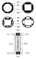
- FIG. 2 shows some embodiments of the fuel cell according to the invention shown, which relate to the membrane-electrode assembly.
- the membrane electrode unit itself already formed circular, can be advantageous only one clamping ring can be used.
- a circular frame may be used for the membrane-electrode assembly become.
- additional clamping jaws can be used optionally.
- square or rectangular membrane-electrode units are suitable also only individual frame pieces, as attack points to serve for the clamping ring.
Landscapes
- Life Sciences & Earth Sciences (AREA)
- Engineering & Computer Science (AREA)
- Manufacturing & Machinery (AREA)
- Sustainable Development (AREA)
- Sustainable Energy (AREA)
- Chemical & Material Sciences (AREA)
- Chemical Kinetics & Catalysis (AREA)
- Electrochemistry (AREA)
- General Chemical & Material Sciences (AREA)
- Fuel Cell (AREA)
Abstract
Description
- Die Dichtung der Testzelle erfolgt über einen Spannring (bei runder Ausführungsform der Brennstoffzelle), der einfach, gleichmäßig und reproduzierbar die Kraft auf die Membran-Elektroden-Einheit überträgt.
- Die Membran-Elektroden-Einheit bleibt als eine Einheit unabhängig von wechselnden Flowfield Platten oder Gasdiffusionsschichten verspannt. Es kann ein definierter Anpressdruck unabhängig von dem der Flowfield Platten eingestellt werden. Damit werden zumindest durch die Membran-Elektroden-Einheit identische Rahmenbedingungen für verschiedene Testläufe geschaffen.
- Die separaten Vorrichtungen zur Aufnahme der Flowfield Platten können einzeln an die Membran-Elektroden-Einheit angebracht werden und ermöglichen einen leichten und problemlosen Austausch, ohne dass die Membran-Elektroden-Einheit demontiert werden muss.
- Der Anpressdruck der einzelnen Flowfields an die Membran-Elektroden-Einheit kann beispielsweise über einen Stempel einzeln definiert eingestellt werden.
- Neben dem leichten Wechsel von Flowfields ist auch der Austausch von Gasdiffusionsschichten der Membran-Elektroden-Einheit problemlos möglich.
Es zeigen:
- Figur 1:
- seitliche Ansicht auf eine Testzelle
- a) gemäß dem Stand der Technik,
- b) erfindungsgemäße Ausführungsform mit
- 1 =
- Rahmen zur Aufnahme der Membran-Elektroden-Einheit,
- 2 =
- Elektroden,
- 3 =
- Membran,
- 4 =
- Schraube,
- 5 =
- Flowfield Platte,
- 6 =
- Kanäle,
- 7 =
- Spannbacken,
- 8 =
- Spannring,
- FSR =
- radiale Kraft beim Spannen des Spannrings,
- F ┴ F SR =
- Kraft senkrecht zur radialen Kraft, bewirkt das Zusammenpressen der Elektroden auf die Membran.
- Figur 2:
- Frontalansicht verschiedener Ausführungsformen der Testzelle mit
- SB =
- Spannbacken,
- SR =
- Spannring,
- R =
- Rahmen zur Aufnahme einer Membran-Elektroden-Einheit ,
- MEA =
- Membran-Elektroden-Einheit.
- Figur 3:
- Schnittzeichnung einer erfindungsgemäßen Brennstoffzelle mit eingetragener
Druckverteilung beim Einspannen mit
- ρDF =
- Druck auf die Dichtflächen und
- ρMEA =
- Druck auf die Membran-Elektroden-Einheit
Claims (12)
- Brennstoffzelle umfassend eine Membran-Elektroden-Einheit und wenigstens zwei Flowfield Platten, dadurch gekennzeichnet, dass die Membran-Elektroden-Einheit separat durch ein Mittel verspannt ist, und die einzelnen Flowfields separat an die Membran-Elektroden-Einheit verspannt sind.
- Brennstoffzelle nach vorhergehendem Anspruch 1, mit wenigstens einer separaten Vorrichtung zur Aufnahme eines Flowfields und/oder einer Gasdiffusionsschicht an einer Seite der Membran-Elektroden-Einheit.
- Brennstoffzelle nach einem der vorhergehenden Ansprüche 1 bis 2, bei dem die separate Vorrichtung an die Membran-Elektroden-Einheit anschraubbar oder mit Hilfe von Schrauben oder Klemmen an diese befestigbar ausgebildet ist.
- Brennstoffzelle nach einem der vorhergehenden Ansprüche 1 bis 3, bei dem die separate Vorrichtung ein Mittel zum Anpressen des Flowfields an die Membran-Elektroden-Einheit aufweist.
- Brennstoffzelle nach vorhergehendem Anspruch 4, mit einem Stempel als Mittel zum Anpressen des Flowfields an die Membran-Elektroden-Einheit.
- Brennstoffzelle nach einem der vorhergehenden Ansprüche 1 bis 5, bei dem der Anpressdruck des Flowfields an die Membran-Elektroden-Einheit über eine Stellschraube einstellbar ist.
- Brennstoffzelle nach einem der vorhergehenden Ansprüche 1 bis 6, bei der die Membran-Elektroden-Einheit kreisförmig ausgebildet ist.
- Brennstoffzelle nach einem der vorhergehenden Ansprüche 1 bis 6, bei dem die Membran-Elektroden-Einheit in einem runden Rahmen angeordnet ist.
- Brennstoffzelle nach einem der vorhergehenden Ansprüche 7 bis 8, die durch einen Spannring verspannt ist.
- Brennstoffzelle nach vorhergehendem Anspruch 9, bei dem der Spannring beim Spannen die radiale Kraft zumindest teilweise in eine Kraft senkrecht zur radialen Spannrichtung umzulenken vermag.
- Brennstoffzelle nach vorhergehendem Anspruch 9, bei dem der Spannring zusätzlich Spannbacken aufweist, die beim Spannen des Spannringes die radiale Kraft zumindest teilweise in eine Kraft senkrecht zur radialen Spannrichtung umzulenken vermögen.
- Brennstoffzelle nach vorhergehendem Anspruch 11, mit konischen Spannbacken.
Applications Claiming Priority (2)
| Application Number | Priority Date | Filing Date | Title |
|---|---|---|---|
| DE102004028625A DE102004028625B4 (de) | 2004-06-12 | 2004-06-12 | Niedertemperatur-Brennstoffzelle |
| DE102004028625 | 2004-06-12 |
Publications (2)
| Publication Number | Publication Date |
|---|---|
| EP1605538A1 true EP1605538A1 (de) | 2005-12-14 |
| EP1605538B1 EP1605538B1 (de) | 2008-08-20 |
Family
ID=34936259
Family Applications (1)
| Application Number | Title | Priority Date | Filing Date |
|---|---|---|---|
| EP05009995A Expired - Lifetime EP1605538B1 (de) | 2004-06-12 | 2005-05-07 | Verspannung einer Niedertemperatur-Brennstoffzelle |
Country Status (3)
| Country | Link |
|---|---|
| EP (1) | EP1605538B1 (de) |
| AT (1) | ATE405961T1 (de) |
| DE (2) | DE102004028625B4 (de) |
Cited By (2)
| Publication number | Priority date | Publication date | Assignee | Title |
|---|---|---|---|---|
| CN110611114A (zh) * | 2019-10-11 | 2019-12-24 | 上海唐锋能源科技有限公司 | 燃料电池膜电极快速测试设备 |
| CN118937843A (zh) * | 2024-07-31 | 2024-11-12 | 浙江亿孚科技有限公司 | 一种碱水电解用膜电极测试装置 |
Citations (3)
| Publication number | Priority date | Publication date | Assignee | Title |
|---|---|---|---|---|
| US3251718A (en) * | 1961-10-26 | 1966-05-17 | Texas Instruments Inc | Screen type fuel cell with foraminous electrolyte carrier |
| WO2002093669A2 (en) * | 2001-05-17 | 2002-11-21 | Johnson Matthey Public Limited Company | Membrane-electrode assembly for polymeric membrane fuel cells |
| US20040086766A1 (en) * | 2001-02-07 | 2004-05-06 | Herbert Hartnack | Fuel cells |
Family Cites Families (3)
| Publication number | Priority date | Publication date | Assignee | Title |
|---|---|---|---|---|
| US6319306B1 (en) * | 2000-03-23 | 2001-11-20 | Idatech, Llc | Hydrogen-selective metal membrane modules and method of forming the same |
| DE19821767C2 (de) * | 1998-05-14 | 2000-06-08 | Siemens Ag | Stapel aus Brennstoffzellen mit Flüssigkeitskühlung und Verfahren zur Kühlung eines BZ-Stapels |
| DE10203612C1 (de) * | 2002-01-23 | 2003-06-26 | Reinz Dichtungs Gmbh & Co Kg | Brennstoffzellenpaket sowie dafür geeignete bipolare Platte |
-
2004
- 2004-06-12 DE DE102004028625A patent/DE102004028625B4/de not_active Expired - Fee Related
-
2005
- 2005-05-07 EP EP05009995A patent/EP1605538B1/de not_active Expired - Lifetime
- 2005-05-07 AT AT05009995T patent/ATE405961T1/de active
- 2005-05-07 DE DE502005005076T patent/DE502005005076D1/de not_active Expired - Lifetime
Patent Citations (3)
| Publication number | Priority date | Publication date | Assignee | Title |
|---|---|---|---|---|
| US3251718A (en) * | 1961-10-26 | 1966-05-17 | Texas Instruments Inc | Screen type fuel cell with foraminous electrolyte carrier |
| US20040086766A1 (en) * | 2001-02-07 | 2004-05-06 | Herbert Hartnack | Fuel cells |
| WO2002093669A2 (en) * | 2001-05-17 | 2002-11-21 | Johnson Matthey Public Limited Company | Membrane-electrode assembly for polymeric membrane fuel cells |
Cited By (2)
| Publication number | Priority date | Publication date | Assignee | Title |
|---|---|---|---|---|
| CN110611114A (zh) * | 2019-10-11 | 2019-12-24 | 上海唐锋能源科技有限公司 | 燃料电池膜电极快速测试设备 |
| CN118937843A (zh) * | 2024-07-31 | 2024-11-12 | 浙江亿孚科技有限公司 | 一种碱水电解用膜电极测试装置 |
Also Published As
| Publication number | Publication date |
|---|---|
| DE502005005076D1 (de) | 2008-10-02 |
| DE102004028625A1 (de) | 2006-01-05 |
| ATE405961T1 (de) | 2008-09-15 |
| DE102004028625B4 (de) | 2007-05-10 |
| EP1605538B1 (de) | 2008-08-20 |
Similar Documents
| Publication | Publication Date | Title |
|---|---|---|
| DE102017119467B4 (de) | Batterieeinrichtung für ein wenigstens teilweise elektrisch betriebenes Kraftfahrzeug | |
| DE102017108413A1 (de) | Elektrochemievorrichtung und Verfahren zur Herstellung einer Elektrochemievorrichtung | |
| EP2065958A1 (de) | Bipolarplatten für Stapel von Brennstoffzellen | |
| EP1870953A1 (de) | Brennstoffzellenstapel | |
| EP1870952A2 (de) | Brennstoffzellenstapel | |
| EP4112782A1 (de) | Montagevorrichtung sowie verwendung der montagevorrichtung zur montage von elektrolysezellen eines elektrolyseurs | |
| DE19821767C2 (de) | Stapel aus Brennstoffzellen mit Flüssigkeitskühlung und Verfahren zur Kühlung eines BZ-Stapels | |
| WO2011026544A1 (de) | Brennstoffzellenstapelabschnitt sowie verfahren zur montage des brennstoffzellenabschnitts | |
| EP1870951A1 (de) | Brennstoffzellenstapel | |
| EP2434570B1 (de) | Elektrochemische Batterie und Verfahren zur Entfernung von Zellen aus einer derartigen Batterie | |
| EP1605538B1 (de) | Verspannung einer Niedertemperatur-Brennstoffzelle | |
| EP0111145B1 (de) | Druckgefäss mit einer flanschartigen Öffnung | |
| DE102012014459B4 (de) | Spannmittel für einen Brennstoffzellenstapel sowie Verfahren zum Verspannen eines Brennstoffzellenstapels | |
| DE102017111514A1 (de) | Gehäuse für einen Stapel aus elektrochemischen Einheiten zur Montage in einer elektrochemischen Vorrichtung | |
| DE102015006297A1 (de) | Aufnahmeeinrichtung für eine Energiespeichereinrichtung | |
| DE102019206175B3 (de) | Brennstoffzellenanordnung | |
| DE10235859B4 (de) | Korrosionsstabiler, gasdichter Medienanschluss für Niedertemperatur-Brennstoffzellen | |
| WO2023156089A1 (de) | Zelllagentrennvorrichtung zum gleichzeitigen trennen von zelllagen eines zellstapels einer brennstoffzelle | |
| EP3621139A1 (de) | Elektrochemische energieumwandlungsvorrichtung | |
| DE102024208119A1 (de) | Elektrolyseur | |
| DE102025100759A1 (de) | Elektrochemisches System mit Druckvergleichmäßigungsplatte | |
| DE102006053978B4 (de) | Brennstoffzellenmodul, damit realisierbare Brennstoffzellenanordnung und zugehöriger Bausatz | |
| DE102015209568A1 (de) | Klemmvorrichtung zum Verbinden von Flanschstegen | |
| DE102022214327A1 (de) | Elektrolyseur | |
| DE102022107433A1 (de) | Spannsystem, Brennstoffzellenanordnung, Fahrzeug und Herstellverfahren für eine Brennstoffzellenanordnung |
Legal Events
| Date | Code | Title | Description |
|---|---|---|---|
| PUAI | Public reference made under article 153(3) epc to a published international application that has entered the european phase |
Free format text: ORIGINAL CODE: 0009012 |
|
| AK | Designated contracting states |
Kind code of ref document: A1 Designated state(s): AT BE BG CH CY CZ DE DK EE ES FI FR GB GR HU IE IS IT LI LT LU MC NL PL PT RO SE SI SK TR |
|
| AX | Request for extension of the european patent |
Extension state: AL BA HR LV MK YU |
|
| 17P | Request for examination filed |
Effective date: 20060412 |
|
| AKX | Designation fees paid |
Designated state(s): AT BE BG CH CY CZ DE DK EE ES FI FR GB GR HU IE IS IT LI LT LU MC NL PL PT RO SE SI SK TR |
|
| GRAP | Despatch of communication of intention to grant a patent |
Free format text: ORIGINAL CODE: EPIDOSNIGR1 |
|
| GRAS | Grant fee paid |
Free format text: ORIGINAL CODE: EPIDOSNIGR3 |
|
| GRAA | (expected) grant |
Free format text: ORIGINAL CODE: 0009210 |
|
| AK | Designated contracting states |
Kind code of ref document: B1 Designated state(s): AT BE BG CH CY CZ DE DK EE ES FI FR GB GR HU IE IS IT LI LT LU MC NL PL PT RO SE SI SK TR |
|
| REG | Reference to a national code |
Ref country code: GB Ref legal event code: FG4D Free format text: NOT ENGLISH |
|
| REG | Reference to a national code |
Ref country code: CH Ref legal event code: EP |
|
| REG | Reference to a national code |
Ref country code: IE Ref legal event code: FG4D Free format text: LANGUAGE OF EP DOCUMENT: GERMAN |
|
| REF | Corresponds to: |
Ref document number: 502005005076 Country of ref document: DE Date of ref document: 20081002 Kind code of ref document: P |
|
| PG25 | Lapsed in a contracting state [announced via postgrant information from national office to epo] |
Ref country code: NL Free format text: LAPSE BECAUSE OF FAILURE TO SUBMIT A TRANSLATION OF THE DESCRIPTION OR TO PAY THE FEE WITHIN THE PRESCRIBED TIME-LIMIT Effective date: 20080820 Ref country code: LT Free format text: LAPSE BECAUSE OF FAILURE TO SUBMIT A TRANSLATION OF THE DESCRIPTION OR TO PAY THE FEE WITHIN THE PRESCRIBED TIME-LIMIT Effective date: 20080820 Ref country code: ES Free format text: LAPSE BECAUSE OF FAILURE TO SUBMIT A TRANSLATION OF THE DESCRIPTION OR TO PAY THE FEE WITHIN THE PRESCRIBED TIME-LIMIT Effective date: 20081201 Ref country code: IS Free format text: LAPSE BECAUSE OF FAILURE TO SUBMIT A TRANSLATION OF THE DESCRIPTION OR TO PAY THE FEE WITHIN THE PRESCRIBED TIME-LIMIT Effective date: 20081220 |
|
| PG25 | Lapsed in a contracting state [announced via postgrant information from national office to epo] |
Ref country code: FI Free format text: LAPSE BECAUSE OF FAILURE TO SUBMIT A TRANSLATION OF THE DESCRIPTION OR TO PAY THE FEE WITHIN THE PRESCRIBED TIME-LIMIT Effective date: 20080820 Ref country code: SI Free format text: LAPSE BECAUSE OF FAILURE TO SUBMIT A TRANSLATION OF THE DESCRIPTION OR TO PAY THE FEE WITHIN THE PRESCRIBED TIME-LIMIT Effective date: 20080820 |
|
| PG25 | Lapsed in a contracting state [announced via postgrant information from national office to epo] |
Ref country code: BG Free format text: LAPSE BECAUSE OF FAILURE TO SUBMIT A TRANSLATION OF THE DESCRIPTION OR TO PAY THE FEE WITHIN THE PRESCRIBED TIME-LIMIT Effective date: 20081120 Ref country code: DK Free format text: LAPSE BECAUSE OF FAILURE TO SUBMIT A TRANSLATION OF THE DESCRIPTION OR TO PAY THE FEE WITHIN THE PRESCRIBED TIME-LIMIT Effective date: 20080820 |
|
| PG25 | Lapsed in a contracting state [announced via postgrant information from national office to epo] |
Ref country code: RO Free format text: LAPSE BECAUSE OF FAILURE TO SUBMIT A TRANSLATION OF THE DESCRIPTION OR TO PAY THE FEE WITHIN THE PRESCRIBED TIME-LIMIT Effective date: 20080820 Ref country code: PT Free format text: LAPSE BECAUSE OF FAILURE TO SUBMIT A TRANSLATION OF THE DESCRIPTION OR TO PAY THE FEE WITHIN THE PRESCRIBED TIME-LIMIT Effective date: 20090120 Ref country code: CZ Free format text: LAPSE BECAUSE OF FAILURE TO SUBMIT A TRANSLATION OF THE DESCRIPTION OR TO PAY THE FEE WITHIN THE PRESCRIBED TIME-LIMIT Effective date: 20080820 Ref country code: SK Free format text: LAPSE BECAUSE OF FAILURE TO SUBMIT A TRANSLATION OF THE DESCRIPTION OR TO PAY THE FEE WITHIN THE PRESCRIBED TIME-LIMIT Effective date: 20080820 |
|
| PLBE | No opposition filed within time limit |
Free format text: ORIGINAL CODE: 0009261 |
|
| STAA | Information on the status of an ep patent application or granted ep patent |
Free format text: STATUS: NO OPPOSITION FILED WITHIN TIME LIMIT |
|
| 26N | No opposition filed |
Effective date: 20090525 |
|
| PG25 | Lapsed in a contracting state [announced via postgrant information from national office to epo] |
Ref country code: EE Free format text: LAPSE BECAUSE OF FAILURE TO SUBMIT A TRANSLATION OF THE DESCRIPTION OR TO PAY THE FEE WITHIN THE PRESCRIBED TIME-LIMIT Effective date: 20080820 |
|
| PG25 | Lapsed in a contracting state [announced via postgrant information from national office to epo] |
Ref country code: IT Free format text: LAPSE BECAUSE OF FAILURE TO SUBMIT A TRANSLATION OF THE DESCRIPTION OR TO PAY THE FEE WITHIN THE PRESCRIBED TIME-LIMIT Effective date: 20080820 |
|
| PG25 | Lapsed in a contracting state [announced via postgrant information from national office to epo] |
Ref country code: SE Free format text: LAPSE BECAUSE OF FAILURE TO SUBMIT A TRANSLATION OF THE DESCRIPTION OR TO PAY THE FEE WITHIN THE PRESCRIBED TIME-LIMIT Effective date: 20081120 |
|
| PG25 | Lapsed in a contracting state [announced via postgrant information from national office to epo] |
Ref country code: PL Free format text: LAPSE BECAUSE OF FAILURE TO SUBMIT A TRANSLATION OF THE DESCRIPTION OR TO PAY THE FEE WITHIN THE PRESCRIBED TIME-LIMIT Effective date: 20080820 |
|
| PG25 | Lapsed in a contracting state [announced via postgrant information from national office to epo] |
Ref country code: GR Free format text: LAPSE BECAUSE OF FAILURE TO SUBMIT A TRANSLATION OF THE DESCRIPTION OR TO PAY THE FEE WITHIN THE PRESCRIBED TIME-LIMIT Effective date: 20081121 |
|
| PG25 | Lapsed in a contracting state [announced via postgrant information from national office to epo] |
Ref country code: HU Free format text: LAPSE BECAUSE OF FAILURE TO SUBMIT A TRANSLATION OF THE DESCRIPTION OR TO PAY THE FEE WITHIN THE PRESCRIBED TIME-LIMIT Effective date: 20090221 |
|
| PGFP | Annual fee paid to national office [announced via postgrant information from national office to epo] |
Ref country code: MC Payment date: 20110523 Year of fee payment: 7 Ref country code: LU Payment date: 20110525 Year of fee payment: 7 |
|
| PG25 | Lapsed in a contracting state [announced via postgrant information from national office to epo] |
Ref country code: TR Free format text: LAPSE BECAUSE OF FAILURE TO SUBMIT A TRANSLATION OF THE DESCRIPTION OR TO PAY THE FEE WITHIN THE PRESCRIBED TIME-LIMIT Effective date: 20080820 |
|
| PG25 | Lapsed in a contracting state [announced via postgrant information from national office to epo] |
Ref country code: CY Free format text: LAPSE BECAUSE OF FAILURE TO SUBMIT A TRANSLATION OF THE DESCRIPTION OR TO PAY THE FEE WITHIN THE PRESCRIBED TIME-LIMIT Effective date: 20080820 |
|
| PG25 | Lapsed in a contracting state [announced via postgrant information from national office to epo] |
Ref country code: MC Free format text: LAPSE BECAUSE OF NON-PAYMENT OF DUE FEES Effective date: 20120531 |
|
| PG25 | Lapsed in a contracting state [announced via postgrant information from national office to epo] |
Ref country code: LU Free format text: LAPSE BECAUSE OF NON-PAYMENT OF DUE FEES Effective date: 20120507 |
|
| REG | Reference to a national code |
Ref country code: FR Ref legal event code: PLFP Year of fee payment: 11 |
|
| PGFP | Annual fee paid to national office [announced via postgrant information from national office to epo] |
Ref country code: CH Payment date: 20150520 Year of fee payment: 11 Ref country code: DE Payment date: 20150415 Year of fee payment: 11 Ref country code: GB Payment date: 20150521 Year of fee payment: 11 |
|
| PGFP | Annual fee paid to national office [announced via postgrant information from national office to epo] |
Ref country code: FR Payment date: 20150519 Year of fee payment: 11 Ref country code: IE Payment date: 20150519 Year of fee payment: 11 Ref country code: BE Payment date: 20150518 Year of fee payment: 11 Ref country code: AT Payment date: 20150520 Year of fee payment: 11 |
|
| PG25 | Lapsed in a contracting state [announced via postgrant information from national office to epo] |
Ref country code: BE Free format text: LAPSE BECAUSE OF NON-PAYMENT OF DUE FEES Effective date: 20160531 |
|
| REG | Reference to a national code |
Ref country code: DE Ref legal event code: R119 Ref document number: 502005005076 Country of ref document: DE |
|
| REG | Reference to a national code |
Ref country code: CH Ref legal event code: PL |
|
| REG | Reference to a national code |
Ref country code: AT Ref legal event code: MM01 Ref document number: 405961 Country of ref document: AT Kind code of ref document: T Effective date: 20160507 |
|
| GBPC | Gb: european patent ceased through non-payment of renewal fee |
Effective date: 20160507 |
|
| PG25 | Lapsed in a contracting state [announced via postgrant information from national office to epo] |
Ref country code: LI Free format text: LAPSE BECAUSE OF NON-PAYMENT OF DUE FEES Effective date: 20160531 Ref country code: CH Free format text: LAPSE BECAUSE OF NON-PAYMENT OF DUE FEES Effective date: 20160531 |
|
| REG | Reference to a national code |
Ref country code: IE Ref legal event code: MM4A |
|
| PG25 | Lapsed in a contracting state [announced via postgrant information from national office to epo] |
Ref country code: AT Free format text: LAPSE BECAUSE OF NON-PAYMENT OF DUE FEES Effective date: 20160507 |
|
| REG | Reference to a national code |
Ref country code: FR Ref legal event code: ST Effective date: 20170131 |
|
| PG25 | Lapsed in a contracting state [announced via postgrant information from national office to epo] |
Ref country code: FR Free format text: LAPSE BECAUSE OF NON-PAYMENT OF DUE FEES Effective date: 20160531 Ref country code: DE Free format text: LAPSE BECAUSE OF NON-PAYMENT OF DUE FEES Effective date: 20161201 |
|
| PG25 | Lapsed in a contracting state [announced via postgrant information from national office to epo] |
Ref country code: IE Free format text: LAPSE BECAUSE OF NON-PAYMENT OF DUE FEES Effective date: 20160507 Ref country code: GB Free format text: LAPSE BECAUSE OF NON-PAYMENT OF DUE FEES Effective date: 20160507 |