EP1605203A2 - Burner and process for combustion of a gas capable of reacting to form solid products - Google Patents
Burner and process for combustion of a gas capable of reacting to form solid products Download PDFInfo
- Publication number
- EP1605203A2 EP1605203A2 EP05011871A EP05011871A EP1605203A2 EP 1605203 A2 EP1605203 A2 EP 1605203A2 EP 05011871 A EP05011871 A EP 05011871A EP 05011871 A EP05011871 A EP 05011871A EP 1605203 A2 EP1605203 A2 EP 1605203A2
- Authority
- EP
- European Patent Office
- Prior art keywords
- gas
- nozzle
- combustion
- oxidant
- precombustion chamber
- Prior art date
- Legal status (The legal status is an assumption and is not a legal conclusion. Google has not performed a legal analysis and makes no representation as to the accuracy of the status listed.)
- Withdrawn
Links
- 238000002485 combustion reaction Methods 0.000 title claims abstract description 154
- 238000000034 method Methods 0.000 title claims abstract description 24
- 230000008569 process Effects 0.000 title claims abstract description 20
- 239000012265 solid product Substances 0.000 title description 3
- 239000007789 gas Substances 0.000 claims abstract description 199
- 239000007800 oxidant agent Substances 0.000 claims abstract description 100
- 230000001590 oxidative effect Effects 0.000 claims abstract description 96
- 238000010099 solid forming Methods 0.000 claims abstract description 37
- 230000003647 oxidation Effects 0.000 claims abstract description 22
- 238000007254 oxidation reaction Methods 0.000 claims abstract description 22
- 230000037361 pathway Effects 0.000 claims abstract description 18
- BLRPTPMANUNPDV-UHFFFAOYSA-N Silane Chemical compound [SiH4] BLRPTPMANUNPDV-UHFFFAOYSA-N 0.000 claims description 24
- 229910000077 silane Inorganic materials 0.000 claims description 21
- VNWKTOKETHGBQD-UHFFFAOYSA-N methane Chemical compound C VNWKTOKETHGBQD-UHFFFAOYSA-N 0.000 claims description 20
- 239000007790 solid phase Substances 0.000 claims description 18
- XYFCBTPGUUZFHI-UHFFFAOYSA-N Phosphine Chemical compound P XYFCBTPGUUZFHI-UHFFFAOYSA-N 0.000 claims description 9
- 239000011261 inert gas Substances 0.000 claims description 9
- RBFQJDQYXXHULB-UHFFFAOYSA-N arsane Chemical compound [AsH3] RBFQJDQYXXHULB-UHFFFAOYSA-N 0.000 claims description 6
- 239000000203 mixture Substances 0.000 claims description 5
- ATUOYWHBWRKTHZ-UHFFFAOYSA-N Propane Chemical compound CCC ATUOYWHBWRKTHZ-UHFFFAOYSA-N 0.000 claims description 4
- 229910000078 germane Inorganic materials 0.000 claims description 4
- 229910000073 phosphorus hydride Inorganic materials 0.000 claims description 4
- 239000005046 Chlorosilane Substances 0.000 claims description 3
- BUGBHKTXTAQXES-UHFFFAOYSA-N Selenium Chemical compound [Se] BUGBHKTXTAQXES-UHFFFAOYSA-N 0.000 claims description 3
- KOPOQZFJUQMUML-UHFFFAOYSA-N chlorosilane Chemical compound Cl[SiH3] KOPOQZFJUQMUML-UHFFFAOYSA-N 0.000 claims description 3
- 229910052751 metal Inorganic materials 0.000 claims description 3
- 239000002184 metal Substances 0.000 claims description 3
- 239000003345 natural gas Substances 0.000 claims description 3
- 229910000058 selane Inorganic materials 0.000 claims description 3
- JLTRXTDYQLMHGR-UHFFFAOYSA-N trimethylaluminium Chemical compound C[Al](C)C JLTRXTDYQLMHGR-UHFFFAOYSA-N 0.000 claims description 3
- XCZXGTMEAKBVPV-UHFFFAOYSA-N trimethylgallium Chemical compound C[Ga](C)C XCZXGTMEAKBVPV-UHFFFAOYSA-N 0.000 claims description 3
- IBEFSUTVZWZJEL-UHFFFAOYSA-N trimethylindium Chemical compound C[In](C)C IBEFSUTVZWZJEL-UHFFFAOYSA-N 0.000 claims description 3
- OTMSDBZUPAUEDD-UHFFFAOYSA-N Ethane Chemical compound CC OTMSDBZUPAUEDD-UHFFFAOYSA-N 0.000 claims description 2
- 238000004891 communication Methods 0.000 claims description 2
- 150000001875 compounds Chemical class 0.000 claims description 2
- 239000001257 hydrogen Substances 0.000 claims description 2
- 229910052739 hydrogen Inorganic materials 0.000 claims description 2
- 230000006872 improvement Effects 0.000 claims description 2
- 230000000737 periodic effect Effects 0.000 claims description 2
- 239000001294 propane Substances 0.000 claims description 2
- 125000004435 hydrogen atom Chemical class [H]* 0.000 claims 1
- 239000007787 solid Substances 0.000 abstract description 14
- 239000000047 product Substances 0.000 description 18
- 239000002245 particle Substances 0.000 description 15
- 239000000446 fuel Substances 0.000 description 10
- XKRFYHLGVUSROY-UHFFFAOYSA-N Argon Chemical compound [Ar] XKRFYHLGVUSROY-UHFFFAOYSA-N 0.000 description 8
- IJGRMHOSHXDMSA-UHFFFAOYSA-N Atomic nitrogen Chemical compound N#N IJGRMHOSHXDMSA-UHFFFAOYSA-N 0.000 description 8
- VYPSYNLAJGMNEJ-UHFFFAOYSA-N Silicium dioxide Chemical compound O=[Si]=O VYPSYNLAJGMNEJ-UHFFFAOYSA-N 0.000 description 8
- 238000000151 deposition Methods 0.000 description 7
- 238000012360 testing method Methods 0.000 description 7
- 239000002912 waste gas Substances 0.000 description 7
- 230000008021 deposition Effects 0.000 description 6
- 238000006243 chemical reaction Methods 0.000 description 5
- 238000007599 discharging Methods 0.000 description 5
- 239000002737 fuel gas Substances 0.000 description 5
- 231100000614 poison Toxicity 0.000 description 5
- 239000002341 toxic gas Substances 0.000 description 5
- 229910052786 argon Inorganic materials 0.000 description 4
- 239000001307 helium Substances 0.000 description 4
- 229910052734 helium Inorganic materials 0.000 description 4
- SWQJXJOGLNCZEY-UHFFFAOYSA-N helium atom Chemical compound [He] SWQJXJOGLNCZEY-UHFFFAOYSA-N 0.000 description 4
- 229910052757 nitrogen Inorganic materials 0.000 description 4
- 231100000331 toxic Toxicity 0.000 description 4
- 230000002588 toxic effect Effects 0.000 description 4
- 239000003440 toxic substance Substances 0.000 description 4
- QVGXLLKOCUKJST-UHFFFAOYSA-N atomic oxygen Chemical compound [O] QVGXLLKOCUKJST-UHFFFAOYSA-N 0.000 description 3
- 230000000694 effects Effects 0.000 description 3
- 238000004519 manufacturing process Methods 0.000 description 3
- 239000011859 microparticle Substances 0.000 description 3
- 239000001301 oxygen Substances 0.000 description 3
- 229910052760 oxygen Inorganic materials 0.000 description 3
- 238000010926 purge Methods 0.000 description 3
- GOLCXWYRSKYTSP-UHFFFAOYSA-N Arsenious Acid Chemical compound O1[As]2O[As]1O2 GOLCXWYRSKYTSP-UHFFFAOYSA-N 0.000 description 2
- ZAMOUSCENKQFHK-UHFFFAOYSA-N Chlorine atom Chemical compound [Cl] ZAMOUSCENKQFHK-UHFFFAOYSA-N 0.000 description 2
- PXGOKWXKJXAPGV-UHFFFAOYSA-N Fluorine Chemical compound FF PXGOKWXKJXAPGV-UHFFFAOYSA-N 0.000 description 2
- NINIDFKCEFEMDL-UHFFFAOYSA-N Sulfur Chemical compound [S] NINIDFKCEFEMDL-UHFFFAOYSA-N 0.000 description 2
- 239000000460 chlorine Substances 0.000 description 2
- 229910052801 chlorine Inorganic materials 0.000 description 2
- 239000000567 combustion gas Substances 0.000 description 2
- 239000012530 fluid Substances 0.000 description 2
- 239000011737 fluorine Substances 0.000 description 2
- 229910052731 fluorine Inorganic materials 0.000 description 2
- 239000011521 glass Substances 0.000 description 2
- 230000002452 interceptive effect Effects 0.000 description 2
- 239000000543 intermediate Substances 0.000 description 2
- 239000000843 powder Substances 0.000 description 2
- 238000012545 processing Methods 0.000 description 2
- 239000004065 semiconductor Substances 0.000 description 2
- 239000000377 silicon dioxide Substances 0.000 description 2
- 235000012239 silicon dioxide Nutrition 0.000 description 2
- LIVNPJMFVYWSIS-UHFFFAOYSA-N silicon monoxide Chemical class [Si-]#[O+] LIVNPJMFVYWSIS-UHFFFAOYSA-N 0.000 description 2
- 239000011593 sulfur Substances 0.000 description 2
- 229910052717 sulfur Inorganic materials 0.000 description 2
- 206010016754 Flashback Diseases 0.000 description 1
- UFHFLCQGNIYNRP-UHFFFAOYSA-N Hydrogen Chemical compound [H][H] UFHFLCQGNIYNRP-UHFFFAOYSA-N 0.000 description 1
- 229920000784 Nomex Polymers 0.000 description 1
- IKWTVSLWAPBBKU-UHFFFAOYSA-N a1010_sial Chemical compound O=[As]O[As]=O IKWTVSLWAPBBKU-UHFFFAOYSA-N 0.000 description 1
- 238000009825 accumulation Methods 0.000 description 1
- 230000009471 action Effects 0.000 description 1
- 230000002776 aggregation Effects 0.000 description 1
- 238000004220 aggregation Methods 0.000 description 1
- 229910000070 arsenic hydride Inorganic materials 0.000 description 1
- 229910000413 arsenic oxide Inorganic materials 0.000 description 1
- 229960002594 arsenic trioxide Drugs 0.000 description 1
- 230000015572 biosynthetic process Effects 0.000 description 1
- 239000001273 butane Substances 0.000 description 1
- 238000001311 chemical methods and process Methods 0.000 description 1
- 239000007795 chemical reaction product Substances 0.000 description 1
- 229910052681 coesite Inorganic materials 0.000 description 1
- 238000009841 combustion method Methods 0.000 description 1
- 239000000356 contaminant Substances 0.000 description 1
- 238000001816 cooling Methods 0.000 description 1
- 229910052906 cristobalite Inorganic materials 0.000 description 1
- 238000013461 design Methods 0.000 description 1
- 238000001514 detection method Methods 0.000 description 1
- -1 diborane Chemical compound 0.000 description 1
- ZOCHARZZJNPSEU-UHFFFAOYSA-N diboron Chemical compound B#B ZOCHARZZJNPSEU-UHFFFAOYSA-N 0.000 description 1
- MROCJMGDEKINLD-UHFFFAOYSA-N dichlorosilane Chemical compound Cl[SiH2]Cl MROCJMGDEKINLD-UHFFFAOYSA-N 0.000 description 1
- YWEUIGNSBFLMFL-UHFFFAOYSA-N diphosphonate Chemical compound O=P(=O)OP(=O)=O YWEUIGNSBFLMFL-UHFFFAOYSA-N 0.000 description 1
- 239000000428 dust Substances 0.000 description 1
- 238000010410 dusting Methods 0.000 description 1
- 239000012717 electrostatic precipitator Substances 0.000 description 1
- 230000008030 elimination Effects 0.000 description 1
- 238000003379 elimination reaction Methods 0.000 description 1
- 229930195733 hydrocarbon Natural products 0.000 description 1
- 150000002430 hydrocarbons Chemical class 0.000 description 1
- 239000013067 intermediate product Substances 0.000 description 1
- 150000002739 metals Chemical class 0.000 description 1
- 238000012986 modification Methods 0.000 description 1
- 230000004048 modification Effects 0.000 description 1
- IJDNQMDRQITEOD-UHFFFAOYSA-N n-butane Chemical compound CCCC IJDNQMDRQITEOD-UHFFFAOYSA-N 0.000 description 1
- OFBQJSOFQDEBGM-UHFFFAOYSA-N n-pentane Natural products CCCCC OFBQJSOFQDEBGM-UHFFFAOYSA-N 0.000 description 1
- 239000002105 nanoparticle Substances 0.000 description 1
- 239000004763 nomex Substances 0.000 description 1
- 238000005457 optimization Methods 0.000 description 1
- 238000013021 overheating Methods 0.000 description 1
- 238000006864 oxidative decomposition reaction Methods 0.000 description 1
- DLYUQMMRRRQYAE-UHFFFAOYSA-N phosphorus pentoxide Inorganic materials O1P(O2)(=O)OP3(=O)OP1(=O)OP2(=O)O3 DLYUQMMRRRQYAE-UHFFFAOYSA-N 0.000 description 1
- 230000007096 poisonous effect Effects 0.000 description 1
- 239000010453 quartz Substances 0.000 description 1
- 239000000376 reactant Substances 0.000 description 1
- 238000004626 scanning electron microscopy Methods 0.000 description 1
- 150000004756 silanes Chemical class 0.000 description 1
- 229910052814 silicon oxide Inorganic materials 0.000 description 1
- 229910001220 stainless steel Inorganic materials 0.000 description 1
- 239000010935 stainless steel Substances 0.000 description 1
- 229910052682 stishovite Inorganic materials 0.000 description 1
- 229910052905 tridymite Inorganic materials 0.000 description 1
- 238000011144 upstream manufacturing Methods 0.000 description 1
- XLYOFNOQVPJJNP-UHFFFAOYSA-N water Substances O XLYOFNOQVPJJNP-UHFFFAOYSA-N 0.000 description 1
Images



Classifications
-
- F—MECHANICAL ENGINEERING; LIGHTING; HEATING; WEAPONS; BLASTING
- F23—COMBUSTION APPARATUS; COMBUSTION PROCESSES
- F23G—CREMATION FURNACES; CONSUMING WASTE PRODUCTS BY COMBUSTION
- F23G7/00—Incinerators or other apparatus for consuming industrial waste, e.g. chemicals
- F23G7/06—Incinerators or other apparatus for consuming industrial waste, e.g. chemicals of waste gases or noxious gases, e.g. exhaust gases
-
- F—MECHANICAL ENGINEERING; LIGHTING; HEATING; WEAPONS; BLASTING
- F23—COMBUSTION APPARATUS; COMBUSTION PROCESSES
- F23C—METHODS OR APPARATUS FOR COMBUSTION USING FLUID FUEL OR SOLID FUEL SUSPENDED IN A CARRIER GAS OR AIR
- F23C7/00—Combustion apparatus characterised by arrangements for air supply
- F23C7/02—Disposition of air supply not passing through burner
-
- F—MECHANICAL ENGINEERING; LIGHTING; HEATING; WEAPONS; BLASTING
- F23—COMBUSTION APPARATUS; COMBUSTION PROCESSES
- F23D—BURNERS
- F23D14/00—Burners for combustion of a gas, e.g. of a gas stored under pressure as a liquid
- F23D14/20—Non-premix gas burners, i.e. in which gaseous fuel is mixed with combustion air on arrival at the combustion zone
-
- F—MECHANICAL ENGINEERING; LIGHTING; HEATING; WEAPONS; BLASTING
- F23—COMBUSTION APPARATUS; COMBUSTION PROCESSES
- F23D—BURNERS
- F23D14/00—Burners for combustion of a gas, e.g. of a gas stored under pressure as a liquid
- F23D14/20—Non-premix gas burners, i.e. in which gaseous fuel is mixed with combustion air on arrival at the combustion zone
- F23D14/22—Non-premix gas burners, i.e. in which gaseous fuel is mixed with combustion air on arrival at the combustion zone with separate air and gas feed ducts, e.g. with ducts running parallel or crossing each other
-
- F—MECHANICAL ENGINEERING; LIGHTING; HEATING; WEAPONS; BLASTING
- F23—COMBUSTION APPARATUS; COMBUSTION PROCESSES
- F23G—CREMATION FURNACES; CONSUMING WASTE PRODUCTS BY COMBUSTION
- F23G7/00—Incinerators or other apparatus for consuming industrial waste, e.g. chemicals
- F23G7/06—Incinerators or other apparatus for consuming industrial waste, e.g. chemicals of waste gases or noxious gases, e.g. exhaust gases
- F23G7/061—Incinerators or other apparatus for consuming industrial waste, e.g. chemicals of waste gases or noxious gases, e.g. exhaust gases with supplementary heating
- F23G7/065—Incinerators or other apparatus for consuming industrial waste, e.g. chemicals of waste gases or noxious gases, e.g. exhaust gases with supplementary heating using gaseous or liquid fuel
-
- F—MECHANICAL ENGINEERING; LIGHTING; HEATING; WEAPONS; BLASTING
- F23—COMBUSTION APPARATUS; COMBUSTION PROCESSES
- F23G—CREMATION FURNACES; CONSUMING WASTE PRODUCTS BY COMBUSTION
- F23G2209/00—Specific waste
- F23G2209/14—Gaseous waste or fumes
- F23G2209/142—Halogen gases, e.g. silane
Definitions
- combustion methods contemplate oxidative decomposition of the toxic substances in the residual, waste gas under combustion conditions whereby the gaseous toxic substances are oxidatively converted into less reactive, often innocuous, reaction products including solid oxides.
- a major problem in the combustion of flammable, and often toxic gases, which generate solid phase oxidation products is one of nozzle plugging and particle build-up in the combustion chamber. Recirculation of the solid phase products in the combustion process often leads to significant deposition of finely divided particles on the burner nozzles thus interfering with combustion. Build-up of the particles can lead to aggregation and potential for incomplete combustion of the residual gases. Intermediate products of incomplete combustion can burn in a downstream part of the process that can sometimes lead to safety issues (e.g., burning holes in filter bags). Complete plugging of the burner nozzles can lead to a pressure increase in the system creating safety issues.
- U.S. 5,957,678 discloses a combustion type detoxifying apparatus for the removal of raw gases such as silane comprised of a combustion chamber, a precombustion chamber located at the top of the combustion chamber and a multi-wall burner attached to the precombustion chamber.
- the multi-wall pipe type burner has: (1) a raw gas nozzle for injecting the feed gas, which is located at the center, (2) a lift gas nozzle for injecting a lift gas, which is arranged to surround the raw gas nozzle, (3) a feed gas combustion-assisting gas nozzle for injecting a gas for assisting combustion of combustible components in the feed gas (i.e., a first oxidant), which is arranged to surround the lift gas nozzle, (4) a fuel gas combustion-assisting gas nozzle for injecting a gas for assisting combustion of a fuel gas (i.e., a second oxidant), which is arranged to surround the residual gas combustion-assisting gas nozzle, and (5) a fuel gas nozzle for injecting the fuel gas, which is arranged to surround the fuel gas combustion-assisting gas nozzle.
- the combustion chamber has a double wall structure containing a cylindrical outer barrel coupled with a fluid nozzle, a porous inner barrel having a constitution such that powders may be prevented from depositing on the inner surface of the inner barrel. If powdery solid oxides are formed during combustion treatment of the raw waste gas, such powders are prevented from being deposited on the inner surface of the inner barrel and interfering with the combustion treatment by passing a pressure fluid through the nozzle in the outer barrel. Thus, the combustion treatment can be carried out in a stable state over an extended period.
- U.S. 4,801,437 discloses a process for combusting poisonous and solid forming gases such as silane , dichlorosilane, germane, etc., wherein combustible exhaust gases and an inert gas, primary and secondary air are downwardly fed through a coaxial, fourfold pipe burner provided with an innermost combustible exhaust gas path, and inert gas path, a primary air path and an outermost secondary air path to form downward flames for combustion. Downward flow is alleged to reduce the amount of deposition of fine dust such as silicon dioxide resulting from combustion on the burner nozzle.
- poisonous and solid forming gases such as silane , dichlorosilane, germane, etc.
- U.S. 5,123,836 discloses the combustion treatment of a toxic gas which forms microparticles on combustion.
- the toxic feed gas is combusted and the combustion gas brought into contact with an aqueous film flowing downward on the inner wall of a furnace from the upper end to the lower end.
- the water captures the microparticles formed on combustion.
- This invention is directed to a combustion apparatus incorporating a combustion chamber, a precombustion chamber and a multi-wall burner and a process for effecting combustion of gases, particularly feed gases containing gases that, on combustion, form solid oxidation products, i.e., solid-forming gases.
- the combustion apparatus comprises:
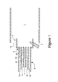
- Figure 1 is a view in cross section of a combustion apparatus showing a multi-wall burner discharging into the entrance of a precombustion chamber and then into the interior portion of a combustion chamber wherein the precombustion chamber resides partially within the combustion chamber.
- Figure 2 is a view in cross section of a combustion apparatus showing a multi-wall burner discharging into a precombustion chamber and then into the combustion chamber wherein the precombustion chamber exit is flush with the opening of the combustion chamber.
- Figure 3 is a view in cross section of a combustion apparatus showing a multi-wall burner discharging into a precombustion chamber and then into the combustion chamber wherein the exit of the precombustion chamber is outside of the entrance to the combustion chamber.
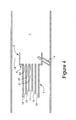
- Figure 4 is a view in cross section of a combustion apparatus showing a multi-wall burner discharging into a precombustion chamber and then into the combustion chamber wherein the burner and precombustion chamber resides entirely in a housing forming the combustion chamber.
- Figure 5 is a view in cross section of a combustion apparatus showing a multi-wall burner discharging into a precombustion chamber and then into the combustion chamber wherein the precombustion chamber resides partially within the combustion chamber.
- the transverse cross-sectional area of the precombustion chamber is greater than the transverse cross-sectional area formed by the outer edge of the outermost nozzle (i.e. there is a step between the precombustion chamber and the outermost nozzle)
- the transverse cross-sectional area of the precombustion chamber is the same as the transverse cross-sectional area formed by the outer edge of the outermost nozzle (i.e., there is no step).
- This invention is directed to a combustion apparatus incorporating a combustion chamber, a precombustion chamber and a multi-wall burner and a process for effecting combustion of gases, particularly feed gases containing gases that form solid oxidation products in said combustion apparatus.
- a combustion chamber 1 is designed for carrying out combustion of solid forming gases in a feed gas, which upon oxidation, form solid phase oxidation products.
- feed gases may be generated as waste gases from industrial processes or such gases may be employed as reactants in chemical processes.
- Solid forming gases flow from an entrance to an interior portion of the combustion chamber to an exit whereby a combustion product including finely divided solid phase particles are exhausted.
- the combustion chamber can be single or multi-walled, with an interior surface designed to inhibit deposition or buildup of solid phase particles on the surface.
- the combustion chamber can be insulated or uninsulated.
- a precombustion chamber 2 Adjacent to combustion chamber 1 is a precombustion chamber 2.
- the precombustion chamber has an entrance and an exit and is disposed at the outlet (nozzle) end of multi-wall burner 3.
- the precombustion chamber is used to effect at least partial combustion of the solid forming gas and prevent recirculation of the solid oxidation products of combustion back to the nozzles of multi-wall burner 3 and accumulating thereon.
- the precombustion chamber 2 preferably is generally circular and has about the same inner diameter as the inner diameter of the outermost wall of multi-wall burner 3, as in Fig 5, so that there is no "step" between the burner and precombustion chamber.
- the precombustion chamber can have an inner diameter larger than the inner diameter of the outermost wall of multi-wall burner 3, i.e., step 5, as shown in Figs 1-4.
- the ratio of the inner diameter of precombustion chamber 2 to that of the outermost wall of the multi-wall burner 3 is from 1 and 1.5.
- the length to diameter ratio (Ud) of the precombustion chamber 2 generally is from about 0.3 to 8 where the diameter is the diameter of the precombustion chamber 2.
- the Ud of the precombustion chamber is from about 0.75 to 3.5.
- the gases including solid particles, pass from the entrance of precombustion chamber 2, through precombustion chamber 2, and then, from its exit to the entrance of combustion chamber 1 and thereby into the interior portion of the combustion chamber 1.
- the precombustion chamber extends beyond the nozzles of multi-wall burner 3 forming a bounded space wherein the combustion reaction can be initiated but only a small fraction of the reaction occurs.
- the multi-wall burner 3 has at least one passageway 11 terminating in nozzle 21 for injecting a feed gas that contains a solid-forming gas, at least one lift gas passageway 12 terminating in nozzle 22 for injecting a lift gas, and at least one passageway 13 terminating in nozzle 23 for injecting an oxidant for assisting combustion of the feed gas (and, if applicable, the lift gas) into the precombustion chamber.
- Nozzle 21 for introducing the feed gas is generally centrally located in the multi-wall burner.
- lift gas nozzle 22 Surrounding nozzle 21 is lift gas nozzle 22, which provides for the introduction of a lift gas.
- nozzle 23 for providing an oxidant, typically an oxygen source such as air.
- the multi-wall burner 3 is constructed of pipes having transverse cross-sections that are generally circular. The nozzle openings for the lift gas nozzle 22 and the oxidant nozzle 23, then, are generally in the form of an annulus.
- an ignition source illustrated as a pilot burner 4
- a pilot burner 4 is employed in precombustion chamber 2.
- the flame reaction zone
- the pilot burner 4 when mounted in the precombustion chamber anchors the flame.
- a UV flame detector (not shown) can optionally be employed downstream of the precombustion chamber in order to detect the existence of combustion, and, if combustion is not detected, the operation can be shut down by suitable controllers. Shutdown can be important to prevent slippage of the combustible gases to downstream equipment, such as filters, which are not suited for combustion.
- An improvement in the combustion apparatus for reducing the deposition of solid phase combustion products on the nozzles, and particularly nozzle 21, resides in the establishment of pathway 14 between the exterior or outer wall of precombustion chamber 2 and the wall bounding or delineating the interior portion of combustion chamber 1.
- combustion chamber 1 is open at the entrance for receiving partially combusted solid forming gases from the precombustion chamber and, thus, the pathway 14 is formed by the space between the exterior or outer wall of precombustion chamber 2 and the interior wall surface establishing the interior portion of combustion chamber 1. In this way, a second oxidant (oxidant) can be introduced through pathway 14 and directly into the interior portion of combustion chamber 1.
- a feed gas containing a solid-forming gas is passed through passageway 11 to nozzle 21, which is centrally located within multi-wall burner 3.
- solid-forming gases which include highly toxic gases employed in the electronics industry, include gaseous compounds of Groups III to V metals of the Periodic Table such as arsine, phosphine, diborane, selenium hydride, silane, germane, chlorosilane, trimethylgallium, trimethylindium, and trimethylaluminum.
- Some of the solid phase oxidation products include arsenic oxide (As 2 O 3 , AsO 5 ) from arsine, phosphorus pentoxide (P 2 O 5 ) from phosphine, and silicon oxides (SiO, SiO 2 ) from silanes.
- the velocity of the feed gas through nozzle 21 is at a rate to achieve desired combustion rates but less than 600 ft/s, more preferably less than 150, ft/s and most preferably less than 100 ft/s, e.g., 5 to 100 ft/sec.
- Feed gas streams containing solid forming gases may be diluted with nitrogen, helium, argon, natural gas, or other non-oxidizing gas, but the apparatus is well-suited for combusting highly concentrated and essentially pure solid-forming gases as the feed gas.
- a lift gas is introduced through passageway 12 to lift gas nozzle 22 to prevent reaction of the solid-forming gas with an oxidant-containing gas at the exit of nozzle 21. Should reaction occur at the tip of the nozzle 21, there may be formation of solid particles that could build up at the tip of nozzle 21 and cause plugging.
- the lift gas is preferably a combustible gas that does not form solid phase oxidation products, such as hydrogen and hydrocarbons including natural gas, methane, ethane, propane, butane and the like, or mixtures thereof.
- the lift gas can also be an inert gas such as nitrogen, helium, or argon or mixtures thereof.
- the lift gas can be a mixture containing one or more combustible gases and inert gases.
- the lift gas is one that is combustible. Such combustion tends to facilitate combustion of the solid-forming gas injected from nozzle 21. Combustion can be established in the combustion chamber and detected by the optional UV detector (not shown) before the feed gas is introduced through the burner. In the absence of combustion of the lift gas, the apparatus is shut down. Not only does a combustible lift gas facilitate combustion, it serves, as does an inert gas, to prevent flash-back of a flame in nozzle 21.
- the nozzle velocity of the lift gas from nozzle 22 is less than 600 ft/s, more preferably between approximately 5 and 100 ft/s and most preferably between approximately 20 and 40 ft/s.
- a first oxidant gas is introduced through passageway 13 and then through nozzle 23 to facilitate at least partial combustion of the solid-forming gas exiting nozzle 21 and lift gas, if combustible, from nozzle 22.
- the first oxidant flow is selected to provide an oxidant layer between the combustion zone and the wall of precombustion chamber 2. This minimizes overheating of the precombustion chamber wall since the oxidant is cooling the wall and the flame does not impinge on the wall.
- the oxidant layer provided by the first oxidant also serves to prevent solid products of combustion from impinging and accumulating on the wall of the precombustion chamber 2.
- the nozzle velocity of the first oxidant from nozzle 23 less than 400 ft/s, more preferably between approximately 5 and 100 ft/s and most preferably between approximately 20 and 40 ft/s.
- the first oxidant can contain oxygen, chlorine, fluorine, or sulfur. These oxidant gases may be essentially pure or diluted with an inert gas such as nitrogen, helium, and argon.
- the first oxidant stream is preferably air. However, if there is interest in producing special compositions of microparticles and nanoparticles, alternative oxidants may be used.
- the ratio of first oxidant stream velocity to the velocity of the lift gas in the range between 0.3 and 3 and more preferably between 0.8 and 1.2.
- the equivalence ratio of the lift gas, if combustible, and first oxidant stream is 0.25 to 4.
- the equivalence ratio of the lift gas, if combustible and the first oxidant is 0.5 to 2.
- the equivalence ratio is defined as the fuel:oxidizer ratio divided by the fuel :oxidizer ratio corresponding to complete combustion. The latter ratio (fuel:oxidizer ratio corresponding to complete combustion) is often referred to as the stoichiometric fuel:oxidizer ratio.
- An equivalence ratio of 1 means that fuel and oxidant are provided in the theoretically correct or stoichiometric amount.
- An equivalence ratio greater than 1 is fuel rich and an equivalence ratio less than 1 is fuel lean.
- a second oxidant is passed through pathway 14 located exterior of precombustion chamber 2 and introduced to the interior of combustion chamber 1. It is independent of the first oxidant stream.
- the second oxidant can contain oxygen, chlorine, fluorine, or sulfur. These oxidant gases may also be diluted with an inert gas such as nitrogen, helium, and argon.
- the second oxidant stream is preferably air.
- the second oxidant is introduced though pathway 14 external to the precombustion chamber 2 and into the interior portion of combustion chamber 1.
- this second oxidant is introduced or drawn into the entrance of combustion chamber 1, and interior portion thereof, by a fan downstream of the combustion chamber (not shown).
- Other means known by those skilled in the art such as an upstream fan and associated ductwork, or jet eductors, can force the second oxidant around precombustion chamber 2, through pathway 14, and into the interior portion of combustion chamber 1.
- the velocity of the second oxidant entering the combustion chamber 1 is generally less than 600 ft/s, more preferably between approximately 5 and 300 ft/s and most preferably between approximately 10 and 100 ft/s.
- the second oxidant stream is provided in an amount exceeding the stoichiometric amount needed to completely combust the lift gas, if combustible, and the feed gas.
- the second oxidant stream can also act to cool the combustion products in the combustion chamber 1.
- the equivalence ratio of the solid forming gas 21 and second oxidant introduced through passageway 14 is generally less than 0.2.
- the solids generated within combustion chamber 1 flow from the exit thereof to a collection system such as a baghouse, electrostatic precipitator, or other solids collection system known in the art (not shown).
- a collection system such as a baghouse, electrostatic precipitator, or other solids collection system known in the art (not shown).
- a burner according to this disclosure was manufactured and tested for the combustion of silane gas.
- the multi-wall burner nozzles had a circular cross section. Details of the apparatus and test conditions for combustion of silane are summarized in Table 1.
- Feed Gas Silane (undiluted) Lift Gas Methane First Oxidant Air Second Oxidant In Pathway 14 Air Diameter Of Combustion Chamber 1 Approximately 8 inches Diameter Of Feed Gas Nozzle 21 0.277 inches Inner Diameter Of Lift Gas Nozzle 22 0.375 inches Outer Diameter Of Lift Gas Nozzle 22 0.495 inches Inner Diameter Of First Oxidant Nozzle 23 0.625 inches Outer Diameter Of First Oxidant Nozzle 23 1.26 inches Inner Diameter Of Precombustion Chamber 2 1.76 inches Precombustion Chamber Inner Diameter 2 To Outermost Nozzle Outer Diameter 23 Ratio 1.4 Precombustion Chamber Length To Diameter Ratio 2.3 Feed Gas Nozzle Velocity 0 to 100 ft/s Lift Gas Nozzle Velocity Approximately 31 ft/s
- the multi-wall burner 3 of the pipe burner type was mounted to introduce the gases into precombustion chamber 2 and then from precombustion chamber 2 to combustion chamber 1.
- Combustion chamber 1 was an 8-inch diameter glass (quartz) pipe, which allowed the flame to be visually observed.
- a blower and associated metal ductwork was located downstream of the combustion chamber with the combustion gases exhausting into a manifold that fed multiple Nomex® filter bags.
- the procedure was as follows. Initially, the blower at the downstream end of combustion chamber 1 was turned on in order to induce airflow through combustion chamber 1 and provide the secondary oxidant to facilitate combustion. Then, the first oxidant stream (air) was established in passageway 13. Fuel and air flows to the pilot burner 4 were established and the pilot burner was ignited. Flame detection by the pilot burner was confirmed before continuing. A lift gas flow, which was methane, (a gaseous fuel stream) was established in passageway 12 and a stable flame was established with the methane lift gas and first oxidant (air). A UV detector confirmed the existence of a flame with the lift gas and first oxidant stream.
- methane a gaseous fuel stream
- the feed gas which was essentially pure silane
- the flow was increased in stepwise fashion up to 100 ft/s over a period of about 1.5 hours.
- combustion was terminated and the multi-wall burner inspected. No blockage of any of the nozzles in multi-wall burner 3 was observed. Only, a very small amount of silica dust was found on the center tube and on the inner wall of the precombustion chamber.
- Example 2 The apparatus of Example 2 was similar to that of Example 1 with minor modifications to the apparatus and operating conditions. Specifically, the inner diameter of the precombustion chamber, the ratio of the inner diameter of the precombustion chamber to the outermost nozzle diameter was reduced (substantially equal as in Fig 5). The precombustion chamber length was the same as in Example 1 resulting in an increase in the precombustion chamber length to diameter ratio. Details of the apparatus and test conditions are summarized in Table 2.
- test configuration was the same as Example 1 with the multi-wall burner, precombustion chamber and operating parameters as given in Table 2. The same procedure for establishing a stable flame with the methane lift gas and first oxidant (air) before introduction of silane was followed.
- the silane velocity was maintained at about 80 ft/s for 45 minutes. Subsequently, the burner was inspected and no silica dust was found on the nozzles and only minimal dusting was found on the precombustion chamber.
- particle samples were collected from the filter bags.
- the particles produced ranged in size from 80 to 320 nm as determined from scanning electron microscopy.
- the construct of the apparatus at a transfill facility was similar to the apparatus at the trial described in Example 2. However, the filter bags were place between the combustion chamber and the induced draft fan. Also the combustion chamber was made of stainless steel instead of glass. The nozzle tips of the burner were rounded to help further minimize build up of particles on the nozzle tips.
- Example 2 In contrast, to Example 2 where the velocity of the silane feed gas was generally held constant, operation at a transfill facility requires that the silane flow be turned on and off thereby resulting in variable silane feed gas nozzle velocities from 0 to 100 ft/sec as the cylinders are emptied. In addition, there are (mainly downstream) pressure fluctuations in the system that affect the flows in the precombustion chamber.
- Example 2 The test showed there was greater build up of particles in the precombustion chamber wall than in Example 2. It is concluded that the process variability caused some backmixing in the precombustion chamber as opposed to a more plug flow vis-à-vis the flows established Example 2.
- Example 2 A test was run in accordance with Example 2 except the velocity of the first oxidant was increased by 50%, i.e., to about 39 ft/sec.
Landscapes
- Engineering & Computer Science (AREA)
- Mechanical Engineering (AREA)
- General Engineering & Computer Science (AREA)
- Environmental & Geological Engineering (AREA)
- Chemical & Material Sciences (AREA)
- Combustion & Propulsion (AREA)
- Incineration Of Waste (AREA)
Abstract
Description
| Feed Gas | Silane (undiluted) |
| Lift Gas | Methane |
| First Oxidant | Air |
| Second | Air |
| Diameter Of | Approximately 8 inches |
| Diameter Of | 0.277 inches |
| Inner Diameter Of | 0.375 inches |
| Outer Diameter Of | 0.495 inches |
| Inner Diameter Of | 0.625 inches |
| Outer Diameter Of | 1.26 inches |
| Inner Diameter Of | 1.76 inches |
| Precombustion | 1.4 |
| Precombustion Chamber Length To Diameter Ratio | 2.3 |
| Feed Gas Nozzle Velocity | 0 to 100 ft/s |
| Lift Gas Nozzle Velocity | Approximately 31 ft/s |
| First Oxidant Nozzle Velocity | Approximately 26 ft/s |
| Second Oxidant Inlet Velocity | Approximately 50 ft/s |
| First Oxidant To Lift Gas Velocity Ratio | 0.84 |
| Lift Gas And First Oxidant Equivalence Ratio | 1.009 |
| Feed Gas And Second Oxidant Equivalence Ratio | 0 to 0.0235 |
| Feed Gas | Silane (undiluted) |
| Lift Gas | Methane |
| First Oxidant | Air |
| Second | Air |
| Diameter Of | Approximately 8 inches |
| Diameter Of | 0.277 inches |
| Inner Diameter Of | 0.375 inches |
| Outer Diameter Of | 0.495 inches |
| Inner Diameter Of | 0.625 inches |
| Outer Diameter Of | 1.26 inches |
| Inner Diameter Of | 1.26 inches |
| Precombustion | 1.0 |
| Precombustion Chamber Length To Diameter Ratio | 3.2 |
| Feed Gas Nozzle Velocity | 0 to 100 ft/s |
| Lift Gas Nozzle Velocity | Approximately 31 ft/s |
| First Oxidant Nozzle Velocity | Approximately 26 ft/s |
| Second Oxidant Inlet Velocity | Approximately 50 ft/s |
| First Oxidant To Lift Gas Velocity Ratio | 0.84 |
| Lift Gas And First Oxidant Equivalence Ratio | 1.009 |
| Feed Gas And Second Oxidant Equivalence Ratio | 0 to 0.0235 |
Claims (23)
- In a combustion apparatus comprising:a combustion chamber having an entrance to an interior portion and an exit therefrom;a precombustion chamber having an entrance and an exit with the exit in communication with the entrance of said combustion chamber;a multi-wall burner having at least one nozzle for injecting a feed gas containing a gas capable of forming solid phase oxidation products, at least one lift gas nozzle for injecting a lift gas, and at least one oxidant nozzle for injecting an oxidant; the respective nozzles directed for injecting into the entrance of said precombustion chamber; the improvement which comprises:a pathway, formed between the exterior of the precombustion chamber and the interior portion of said combustion chamber, whereby said pathway permits the introduction of a secondary oxidant exterior to the precombustion chamber and into the interior portion of the combustion chamber.
- The combustion apparatus of Claim 1 wherein said lift gas passageway surrounds said feed gas nozzle.
- The apparatus of Claim 2 wherein said oxidant nozzle surrounds said lift gas nozzle.
- The apparatus of Claim 3 wherein the multi-wall burner is a pipe burner.
- The apparatus of Claim 4 wherein a constant ignition source is provided in said precombustion chamber.
- The apparatus of Claim 4 wherein the length to diameter ratio of the precombustion chamber is from 0.3 to 8.
- The apparatus of Claim 6, wherein the length to diameter ratio of the precombustion chamber is 0.75 to 3.5.
- A process for the combustion treatment of a feed gas containing a solid forming gas that forms solid phase oxidation products on combustion, which comprises:injecting said feed gas containing said solid-forming gas into a precombustion chamber through a first nozzle;injecting an oxidant into said precombustion chamber through a second nozzle;injecting a lift gas into said precombustion chamber through a third nozzle disposed between said first nozzle and said second nozzle;at least partially combusting said solid forming gas in said precombustion chamber;exhausting the partially combusted gases generated in the precombustion chamber into an interior portion of a combustion chamber for effecting further combustion thereof; and,introducing a second oxidant into the interior portion of said combustion chamber through a pathway formed between the exterior of said precombustion chamber and interior portion of said combustion chamber.
- The process of claim 8 wherein said solid-forming gas is a gaseous compound selected from the group consisting of a Groups III to V metal of the Periodic Table.
- The process of Claim 9 wherein the solid forming gas is selected from the group consisting of silane, arsine, phosphine, germane, diborane, selenium hydride, monosilane, chlorosilane, trimethylgallium, trimethylindium, and trimethylaluminum.
- The process of Claim 8 wherein the lift gas is selected from the group consisting of natural gas, hydrogen, methane, ethane, propane, and mixtures thereof.
- The process of Claim 8 wherein the velocity of the feed gas through the first nozzle is from 5 to 100 feet per second and the velocity of the lift gas though said second nozzle is from 5 to 100 feet per second.
- The process of Claim 12 wherein the equivalence ratio of the lift gas and first oxidant is from 0.5 to 2 and the ratio of the velocity of the first oxidant to the velocity of the lift gas is from 0.8 to 1.2.
- A combustion apparatus comprising:a multi-wall burner having a feed gas nozzle for injecting a feed gas containing a gas capable of forming solid phase oxidation products, a lift gas nozzle for injecting a lift gas, and a first oxidant nozzle for injecting a first oxidant, wherein said lift gas nozzle is disposed between said feed gas nozzle and said first oxidant nozzle, said multi-wall burner having an inlet end and a nozzle end;a precombustion chamber with a first end attached to the nozzle end of said multi-wall burner and a second end adapted to expel said feed gas, said lift gas, and said first oxidant;a combustion chamber having an opening adapted for receiving said feed gas, said lift gas, and said first oxidant from said precombustion chamber; anda means for introducing a second oxidant into said combustion chamber external to and generally around said precombustion chamber.
- The apparatus of Claim 14 wherein a constant ignition source is provided in said precombustion chamber.
- The apparatus of Claim 14 wherein the length to diameter ratio of the precombustion chamber is from 0.3 to 8.
- The apparatus of Claim 16, wherein the length to diameter ratio of the precombustion chamber is 0.75 to 3.5.
- A process for the combustion treatment of a feed gas containing a solid forming gas that forms solid phase oxidation products on combustion, which comprises:injecting said feed gas containing said solid-forming gas into a precombustion chamber through a first nozzle;injecting an oxidant into said precombustion chamber through a second nozzle;injecting a lift gas into said precombustion chamber through a third nozzle disposed between said first nozzle and said second nozzle;at least partially combusting said solid forming gas in said precombustion chamber;introducing the partially combusted gases generated in the precombustion chamber into a combustion chamber for effecting further combustion thereof; and,introducing a second oxidant into said combustion chamber through a pathway external to said precombustion chamber for combusting said solid forming gas.
- The process of Claim 18 wherein the solid forming gas is selected from the group consisting of silane, arsine, phosphine, germane, diborane, selenium hydride, monosilane, chlorosilane, trimethylgallium, trimethylindium, and trimethylaluminum.
- The process of Claim 18 wherein the lift gas comprises a combustible gas that does not form solid phase oxidation products and optionally an inert gas.
- The process of Claim 18 wherein the velocity of the feed gas through the first nozzle is from 5 to 100 feet per second and the velocity of the lift gas though said second nozzle is from 5 to 100 feet per second.
- The process of Claim 21 wherein the equivalence ratio of the lift gas and first oxidant is from 0.5 to 2 and the ratio of the velocity of the first oxidant to the velocity of the lift gas is from 0.8 to 1.2.
- The process of Claim 18 wherein the equivalence ratio of the feed gas and the second oxidant is less than 0.2.
Applications Claiming Priority (2)
| Application Number | Priority Date | Filing Date | Title |
|---|---|---|---|
| US862851 | 2004-06-07 | ||
| US10/862,851 US7074034B2 (en) | 2004-06-07 | 2004-06-07 | Burner and process for combustion of a gas capable of reacting to form solid products |
Publications (2)
| Publication Number | Publication Date |
|---|---|
| EP1605203A2 true EP1605203A2 (en) | 2005-12-14 |
| EP1605203A3 EP1605203A3 (en) | 2008-04-16 |
Family
ID=34937153
Family Applications (1)
| Application Number | Title | Priority Date | Filing Date |
|---|---|---|---|
| EP05011871A Withdrawn EP1605203A3 (en) | 2004-06-07 | 2005-06-01 | Burner and process for combustion of a gas capable of reacting to form solid products |
Country Status (8)
| Country | Link |
|---|---|
| US (1) | US7074034B2 (en) |
| EP (1) | EP1605203A3 (en) |
| JP (1) | JP2005351615A (en) |
| KR (1) | KR100704217B1 (en) |
| CN (1) | CN100549526C (en) |
| IL (1) | IL168911A (en) |
| SG (1) | SG118345A1 (en) |
| TW (1) | TWI271491B (en) |
Families Citing this family (15)
| Publication number | Priority date | Publication date | Assignee | Title |
|---|---|---|---|---|
| SE0501840L (en) * | 2005-08-19 | 2007-02-20 | Aga Ab | Procedure as well as for monitoring a burner |
| US20070231761A1 (en) * | 2006-04-03 | 2007-10-04 | Lee Rosen | Integration of oxy-fuel and air-fuel combustion |
| GB0613044D0 (en) * | 2006-06-30 | 2006-08-09 | Boc Group Plc | Gas combustion apparatus |
| US7717701B2 (en) * | 2006-10-24 | 2010-05-18 | Air Products And Chemicals, Inc. | Pulverized solid fuel burner |
| EP2326878A2 (en) * | 2008-09-26 | 2011-06-01 | Air Products and Chemicals, Inc. | Combustion system with precombustor for recycled flue gas |
| US8689710B2 (en) * | 2008-09-26 | 2014-04-08 | Air Products And Chemicals, Inc. | Combustion system with precombustor |
| JP5659491B2 (en) * | 2009-01-30 | 2015-01-28 | セントラル硝子株式会社 | Semiconductor manufacturing equipment including fluorine gas generator |
| US9683736B2 (en) * | 2011-11-11 | 2017-06-20 | Air Products And Chemicals, Inc. | Precombustor system and method for combustion for biomass |
| CN104296133B (en) * | 2014-10-28 | 2017-06-06 | 山东博润工业技术股份有限公司 | A kind of low heat value solid powder burner |
| US10995388B2 (en) * | 2017-04-27 | 2021-05-04 | Jfe Steel Corporation | Method for manufacturing sintered ore |
| JP6734821B2 (en) * | 2017-07-13 | 2020-08-05 | 大陽日酸株式会社 | Combustion nozzle, combustion cylinder, and combustion abatement device |
| GB2586706A (en) * | 2019-08-21 | 2021-03-03 | Csk Inc | A burner for scrubbers |
| KR102325814B1 (en) * | 2019-08-21 | 2021-11-11 | 씨에스케이(주) | Burner for Scrubber |
| DE102021103365B4 (en) | 2021-02-12 | 2024-02-15 | Das Environmental Expert Gmbh | Process and burner for the thermal disposal of pollutants in process gases |
| CN117823897B (en) * | 2024-02-05 | 2024-07-05 | 中国矿业大学 | Combustor for full-concentration combustion utilization of low-concentration gas |
Family Cites Families (11)
| Publication number | Priority date | Publication date | Assignee | Title |
|---|---|---|---|---|
| US2952310A (en) * | 1955-02-22 | 1960-09-13 | Shell Dev | Burning of regenerator flue gas |
| US4347052A (en) * | 1978-06-19 | 1982-08-31 | John Zink Company | Low NOX burner |
| US4801437A (en) | 1985-12-04 | 1989-01-31 | Japan Oxygen Co., Ltd. | Process for treating combustible exhaust gases containing silane and the like |
| FR2612606B1 (en) * | 1987-03-18 | 1990-09-14 | Air Liquide | METHOD AND DEVICE FOR DESTRUCTION OF TOXIC GASEOUS EFFLUENTS |
| US5123836A (en) | 1988-07-29 | 1992-06-23 | Chiyoda Corporation | Method for the combustion treatment of toxic gas-containing waste gas |
| JP3486022B2 (en) * | 1995-10-16 | 2004-01-13 | ジャパン・エア・ガシズ株式会社 | Exhaust gas treatment equipment |
| JP3490843B2 (en) * | 1996-06-19 | 2004-01-26 | 日本エドワーズ株式会社 | Exhaust gas combustion method and apparatus |
| JPH10110926A (en) * | 1996-08-14 | 1998-04-28 | Nippon Sanso Kk | Combustion type abatement system |
| JP4066107B2 (en) * | 1997-11-21 | 2008-03-26 | 株式会社荏原製作所 | Combustor for exhaust gas treatment |
| US6423284B1 (en) * | 1999-10-18 | 2002-07-23 | Advanced Technology Materials, Inc. | Fluorine abatement using steam injection in oxidation treatment of semiconductor manufacturing effluent gases |
| DE60308071T3 (en) * | 2002-01-31 | 2012-10-25 | Air Products And Chemicals, Inc. | Burner for process heating with very low NOx emission |
-
2004
- 2004-06-07 US US10/862,851 patent/US7074034B2/en not_active Expired - Lifetime
-
2005
- 2005-06-01 TW TW094118080A patent/TWI271491B/en not_active IP Right Cessation
- 2005-06-01 SG SG200503493A patent/SG118345A1/en unknown
- 2005-06-01 EP EP05011871A patent/EP1605203A3/en not_active Withdrawn
- 2005-06-01 IL IL168911A patent/IL168911A/en not_active IP Right Cessation
- 2005-06-02 JP JP2005162386A patent/JP2005351615A/en active Pending
- 2005-06-03 KR KR1020050047815A patent/KR100704217B1/en not_active Expired - Fee Related
- 2005-06-07 CN CNB2005100761516A patent/CN100549526C/en not_active Expired - Fee Related
Also Published As
| Publication number | Publication date |
|---|---|
| CN100549526C (en) | 2009-10-14 |
| IL168911A (en) | 2007-12-03 |
| TWI271491B (en) | 2007-01-21 |
| JP2005351615A (en) | 2005-12-22 |
| EP1605203A3 (en) | 2008-04-16 |
| TW200540370A (en) | 2005-12-16 |
| US7074034B2 (en) | 2006-07-11 |
| SG118345A1 (en) | 2006-01-27 |
| KR100704217B1 (en) | 2007-04-09 |
| KR20060048185A (en) | 2006-05-18 |
| US20050287487A1 (en) | 2005-12-29 |
| CN1707161A (en) | 2005-12-14 |
Similar Documents
| Publication | Publication Date | Title |
|---|---|---|
| US7074034B2 (en) | Burner and process for combustion of a gas capable of reacting to form solid products | |
| US5891404A (en) | Exhaust gas treatment unit | |
| JP5347183B2 (en) | Method and apparatus for removing fluorine from a gas stream | |
| EP0694735B9 (en) | Combustive destruction of noxious substances | |
| EP2986356B1 (en) | Extended or multiple reaction zones in scrubbing apparatus | |
| JP5102217B2 (en) | Process reduction reactor | |
| CN101175949B (en) | Apparatus and method for combusting exhaust gases | |
| CN88101392A (en) | Processes and devices for the destruction of toxic waste gases | |
| CN1997439A (en) | Apparatus and method for controlled combustion of gaseous pollutants | |
| JP4885855B2 (en) | Gas reduction | |
| US5213492A (en) | Combustion method for simultaneous control of nitrogen oxides and products of incomplete combustion | |
| EP0262561A2 (en) | Method of burning waste gases from semiconductor-manufacturing processes and an apparatus for burning the waste gases | |
| US5242295A (en) | Combustion method for simultaneous control of nitrogen oxides and products of incomplete combustion | |
| WO2000050155A1 (en) | Method and apparatus for combining reactive gases while delaying reaction between same | |
| EP0663564B1 (en) | Combustion method for simultaneous control of nitrogen oxides and products of incomplete combustion | |
| JPH02103311A (en) | Method of treatment of poisonous flue gas by combustion | |
| TW201312055A (en) | Exhaust gas combustion apparatus | |
| CN115210502B (en) | Method and burner for thermally removing harmful substances from process gases | |
| JP4528141B2 (en) | Flame retardant decomposition burner | |
| JP3993686B2 (en) | Exhaust gas abatement system | |
| JP2963792B2 (en) | Method and apparatus for treating toxic exhaust gas | |
| TWI862724B (en) | Method of optimising operating conditions in an abatement apparatus, and apparatus for optimising/adjusting operating conditions in an abatement apparatus |
Legal Events
| Date | Code | Title | Description |
|---|---|---|---|
| PUAI | Public reference made under article 153(3) epc to a published international application that has entered the european phase |
Free format text: ORIGINAL CODE: 0009012 |
|
| AK | Designated contracting states |
Kind code of ref document: A2 Designated state(s): AT BE BG CH CY CZ DE DK EE ES FI FR GB GR HU IE IS IT LI LT LU MC NL PL PT RO SE SI SK TR |
|
| AX | Request for extension of the european patent |
Extension state: AL BA HR LV MK YU |
|
| PUAL | Search report despatched |
Free format text: ORIGINAL CODE: 0009013 |
|
| AK | Designated contracting states |
Kind code of ref document: A3 Designated state(s): AT BE BG CH CY CZ DE DK EE ES FI FR GB GR HU IE IS IT LI LT LU MC NL PL PT RO SE SI SK TR |
|
| AX | Request for extension of the european patent |
Extension state: AL BA HR LV MK YU |
|
| 17P | Request for examination filed |
Effective date: 20080609 |
|
| AKX | Designation fees paid |
Designated state(s): AT BE BG CH CY CZ DE DK EE ES FI FR GB GR HU IE IS IT LI LT LU MC NL PL PT RO SE SI SK TR |
|
| 17Q | First examination report despatched |
Effective date: 20090901 |
|
| STAA | Information on the status of an ep patent application or granted ep patent |
Free format text: STATUS: THE APPLICATION IS DEEMED TO BE WITHDRAWN |
|
| 18D | Application deemed to be withdrawn |
Effective date: 20100101 |