EP1605149A1 - Sensor module unit and throttle device with the same - Google Patents
Sensor module unit and throttle device with the same Download PDFInfo
- Publication number
- EP1605149A1 EP1605149A1 EP04712155A EP04712155A EP1605149A1 EP 1605149 A1 EP1605149 A1 EP 1605149A1 EP 04712155 A EP04712155 A EP 04712155A EP 04712155 A EP04712155 A EP 04712155A EP 1605149 A1 EP1605149 A1 EP 1605149A1
- Authority
- EP
- European Patent Office
- Prior art keywords
- intake
- throttle
- holding portion
- sensor
- air pressure
- Prior art date
- Legal status (The legal status is an assumption and is not a legal conclusion. Google has not performed a legal analysis and makes no representation as to the accuracy of the status listed.)
- Withdrawn
Links
Images





Classifications
-
- F—MECHANICAL ENGINEERING; LIGHTING; HEATING; WEAPONS; BLASTING
- F02—COMBUSTION ENGINES; HOT-GAS OR COMBUSTION-PRODUCT ENGINE PLANTS
- F02D—CONTROLLING COMBUSTION ENGINES
- F02D35/00—Controlling engines, dependent on conditions exterior or interior to engines, not otherwise provided for
-
- F—MECHANICAL ENGINEERING; LIGHTING; HEATING; WEAPONS; BLASTING
- F02—COMBUSTION ENGINES; HOT-GAS OR COMBUSTION-PRODUCT ENGINE PLANTS
- F02D—CONTROLLING COMBUSTION ENGINES
- F02D11/00—Arrangements for, or adaptations to, non-automatic engine control initiation means, e.g. operator initiated
- F02D11/06—Arrangements for, or adaptations to, non-automatic engine control initiation means, e.g. operator initiated characterised by non-mechanical control linkages, e.g. fluid control linkages or by control linkages with power drive or assistance
- F02D11/10—Arrangements for, or adaptations to, non-automatic engine control initiation means, e.g. operator initiated characterised by non-mechanical control linkages, e.g. fluid control linkages or by control linkages with power drive or assistance of the electric type
-
- F—MECHANICAL ENGINEERING; LIGHTING; HEATING; WEAPONS; BLASTING
- F02—COMBUSTION ENGINES; HOT-GAS OR COMBUSTION-PRODUCT ENGINE PLANTS
- F02D—CONTROLLING COMBUSTION ENGINES
- F02D9/00—Controlling engines by throttling air or fuel-and-air induction conduits or exhaust conduits
-
- F—MECHANICAL ENGINEERING; LIGHTING; HEATING; WEAPONS; BLASTING
- F02—COMBUSTION ENGINES; HOT-GAS OR COMBUSTION-PRODUCT ENGINE PLANTS
- F02D—CONTROLLING COMBUSTION ENGINES
- F02D9/00—Controlling engines by throttling air or fuel-and-air induction conduits or exhaust conduits
- F02D9/08—Throttle valves specially adapted therefor; Arrangements of such valves in conduits
- F02D9/10—Throttle valves specially adapted therefor; Arrangements of such valves in conduits having pivotally-mounted flaps
- F02D9/1035—Details of the valve housing
- F02D9/105—Details of the valve housing having a throttle position sensor
-
- F—MECHANICAL ENGINEERING; LIGHTING; HEATING; WEAPONS; BLASTING
- F16—ENGINEERING ELEMENTS AND UNITS; GENERAL MEASURES FOR PRODUCING AND MAINTAINING EFFECTIVE FUNCTIONING OF MACHINES OR INSTALLATIONS; THERMAL INSULATION IN GENERAL
- F16K—VALVES; TAPS; COCKS; ACTUATING-FLOATS; DEVICES FOR VENTING OR AERATING
- F16K37/00—Special means in or on valves or other cut-off apparatus for indicating or recording operation thereof, or for enabling an alarm to be given
- F16K37/0025—Electrical or magnetic means
- F16K37/0041—Electrical or magnetic means for measuring valve parameters
-
- F—MECHANICAL ENGINEERING; LIGHTING; HEATING; WEAPONS; BLASTING
- F16—ENGINEERING ELEMENTS AND UNITS; GENERAL MEASURES FOR PRODUCING AND MAINTAINING EFFECTIVE FUNCTIONING OF MACHINES OR INSTALLATIONS; THERMAL INSULATION IN GENERAL
- F16K—VALVES; TAPS; COCKS; ACTUATING-FLOATS; DEVICES FOR VENTING OR AERATING
- F16K37/00—Special means in or on valves or other cut-off apparatus for indicating or recording operation thereof, or for enabling an alarm to be given
- F16K37/0025—Electrical or magnetic means
- F16K37/005—Electrical or magnetic means for measuring fluid parameters
-
- F—MECHANICAL ENGINEERING; LIGHTING; HEATING; WEAPONS; BLASTING
- F02—COMBUSTION ENGINES; HOT-GAS OR COMBUSTION-PRODUCT ENGINE PLANTS
- F02D—CONTROLLING COMBUSTION ENGINES
- F02D9/00—Controlling engines by throttling air or fuel-and-air induction conduits or exhaust conduits
- F02D9/02—Controlling engines by throttling air or fuel-and-air induction conduits or exhaust conduits concerning induction conduits
- F02D2009/0201—Arrangements; Control features; Details thereof
- F02D2009/0294—Throttle control device with provisions for actuating electric or electronic sensors
-
- F—MECHANICAL ENGINEERING; LIGHTING; HEATING; WEAPONS; BLASTING
- F02—COMBUSTION ENGINES; HOT-GAS OR COMBUSTION-PRODUCT ENGINE PLANTS
- F02D—CONTROLLING COMBUSTION ENGINES
- F02D2200/00—Input parameters for engine control
- F02D2200/02—Input parameters for engine control the parameters being related to the engine
- F02D2200/04—Engine intake system parameters
- F02D2200/0404—Throttle position
-
- F—MECHANICAL ENGINEERING; LIGHTING; HEATING; WEAPONS; BLASTING
- F02—COMBUSTION ENGINES; HOT-GAS OR COMBUSTION-PRODUCT ENGINE PLANTS
- F02D—CONTROLLING COMBUSTION ENGINES
- F02D2200/00—Input parameters for engine control
- F02D2200/02—Input parameters for engine control the parameters being related to the engine
- F02D2200/04—Engine intake system parameters
- F02D2200/0406—Intake manifold pressure
-
- F—MECHANICAL ENGINEERING; LIGHTING; HEATING; WEAPONS; BLASTING
- F02—COMBUSTION ENGINES; HOT-GAS OR COMBUSTION-PRODUCT ENGINE PLANTS
- F02D—CONTROLLING COMBUSTION ENGINES
- F02D2200/00—Input parameters for engine control
- F02D2200/02—Input parameters for engine control the parameters being related to the engine
- F02D2200/04—Engine intake system parameters
- F02D2200/0414—Air temperature
-
- F—MECHANICAL ENGINEERING; LIGHTING; HEATING; WEAPONS; BLASTING
- F02—COMBUSTION ENGINES; HOT-GAS OR COMBUSTION-PRODUCT ENGINE PLANTS
- F02D—CONTROLLING COMBUSTION ENGINES
- F02D41/00—Electrical control of supply of combustible mixture or its constituents
- F02D41/02—Circuit arrangements for generating control signals
- F02D41/18—Circuit arrangements for generating control signals by measuring intake air flow
- F02D41/187—Circuit arrangements for generating control signals by measuring intake air flow using a hot wire flow sensor
Definitions
- the present invention relates to a structure for installing sensors to detect various kinds of data indispensable to fuel supply control and intake-air flow rate control of an internal-combustion engine.
- an internal-combustion engine (hereinafter, referred to as an "engine” as appropriate) of a vehicle including at least a large-size motorcycle is controlled by an electronic control apparatus provided with a computer.
- various kinds of sensors to always detect the operation state and intake-air state of the engine are disposed in the engine and its peripheral apparatuses, and ECU (Electronic Control Unit) that performs electronic concentrated engine control carries out optimal control of the engine based on a variety of data sent from the various kinds of sensors.
- ECU Electronic Control Unit
- the fuel such as gasoline and air
- the air mixed fuel is burned in a piston to produce torque, and therefore, optimization is important on intake-air flow rate control as well as fuel supply quantity control of the engine.
- An intake-air flow rate to supply to the engine is adjusted by a throttle apparatus provided on the inlet pipe side connected to the engine.
- the throttle apparatus is generally comprised of an intake-air cylindrical pipe provided with a throttle valve therein, and the air flow rate is adjusted by adjusting an opening angle of the throttle valve (hereinafter, referred to as simply "throttle").
- the ECU needs to always detect an opening angle of the throttle in the intake-air throttle apparatus with accuracy, and detection of the throttle opening angle is performed based on an output signal of a throttle position sensor (hereinafter, referred to as "TPS") disposed near the throttle.
- TPS throttle position sensor
- the TPS is broadly divided into two types, a contact type and non-contact type.
- a contact type a potentiometer is installed to gear to the operation of a throttle, a contact member is brought into contact with a resistant film, and thus the throttle opening angle is detected
- the non-contact type the throttle opening angle is detected using a hall element or MR element that is not in direct contact with a movable member gearing to the throttle.
- the contact type TPS using the potentiometer requires high positioning precision when installed to a throttle body.
- it is necessary to adjust the position in the vicinity of a throttle axis while monitoring a signal output from the TPS for example, see Patent Document JP H11-223508,.
- Such an adjustment needs to be performed for each throttle body in the case of a multi-cylinder engine, and the assembling operation becomes extremely complicated.
- the method contributes to reduction in operation of wiring between the sensors and ECU substrate, but imposes large limitations not only in size of the throttle apparatus and internal and external shapes of the throttle body but also in size of the ECU substrate and arrangement positions of electric components in the substrate. Therefore, particularly, it is sometimes difficult to mount such a substrate on a small-size throttle apparatus for a two-wheel motorcycle or compact-size car.
- the present invention provides a sensor module unit which is integrally provided with a plurality of sensors necessary for fuel supply control and intake-air flow rate control in an internal-combustion engine, and has an intake-air temperature sensor holding portion installed with an intake-air temperature sensor, at least one of a throttle position sensor holding portion installed with a position sensor to detect an opening angle of a throttle valve in an intake throttle apparatus and an intake-air pressure sensor holding portion installed with an intake-air pressure sensor, and a unit main body that integrally accommodates the intake-air temperature sensor holding portion, and at least one of the throttle position sensor holding portion and the intake-air pressure sensor holding portion to position in respective predetermined arrangement positions in the unit, whereby each of the plurality of sensors is positioned in a predetermined measuring position in the throttle apparatus when the unit main body is installed in the vicinity of a throttle axis of the intake throttle apparatus.
- the intake-air temperature sensor is positioned on an intake upstream side of the throttle valve, while the intake-air pressure sensor is positioned on an intake downstream side of the throttle valve if the unit has the intake-air pressure sensor holding portion.
- the unit is provided with an outside-air pressure sensor holding portion installed with an outside-air pressure sensor in a position adjacent to the intake-air temperature sensor holding portion in the unit main body, substituting for or together with the intake-air pressure sensor holding portion, and thus flexibly supports a combination of sensors to install.
- the outside-air pressure sensor is arranged on the intake upstream side of the throttle valve when the unit is installed in the intake throttle apparatus.
- the temperature sensor holding portion determines positioning in the vicinity of the throttle axis when the unit main body is installed in the intake throttle apparatus.
- the temperature sensor holding portion is a conduit projecting to reach an inner wall of a throttle body of the intake throttle apparatus, and the positioning is carried out by the conduit being engaged in an opening provided in the throttle body.
- the throttle position sensor is a non-contact type position sensor such as a hall element and MR element to detect an opening angle of the throttle valve. The need is thus eliminated for complicated installation and adjustment operation of the throttle position sensor.
- the sensor module unit is provided with a circuit substrate to which are connected sensor output lines from the plurality of sensors, and the circuit substrate has output signal adjusting means for converting at least a sensor output from the non-contact type position sensor into a predetermined output signal.
- the circuit substrate is provided with interface means for transmitting outputs of the plurality of sensors or the output signal to an external electronic fuel injection control apparatus having an intake throttle valve control apparatus or intake throttle control apparatus.
- the present invention further provides an intake throttle valve control apparatus and intake throttle apparatus including such a sensor module unit.
- each of a plurality of sensors when the unit main body is installed in the vicinity of the throttle axis of the intake throttle apparatus, each of a plurality of sensors is positioned in a predetermined measuring position in the throttle apparatus, whereby it is possible to remarkably facilitate installation of the plurality of sensors arranged on the inlet pipe side of an engine, achieve positioning of each of the sensors in an accurate measuring position, and eliminate limitations in size and shape of an apparatus targeted for installation of the sensors.
- FIG.1 shows a sensor module unit 1 installed in a side surface of a throttle body 20 in the vicinity of a throttle axis 15 in a throttle apparatus 2.
- the left side of the throttle axis 15 is an intake upstream side (air-filter side), while the right side of the throttle axis 15 is an intake downstream side (engine side).
- the throttle body 20 is formed in the shape of a cylinder and provided with an air horn 10A at its left end and with a flange 10B at its right end.
- the throttle apparatus 2 increases or decreases a passage area of the filtered air by narrowing or widening an opening angle of a throttle valve 18 to control an intake-air flow rate to the engine.
- the throttle axis 15 to adjust the intake-air flow rate is provided substantially in the center of the side surface of the throttle body 20, and the throttle valve 18 is coupled to the throttle axis 15.
- the opening angle of the throttle valve 18 is detected sing a non-contact type position sensor (TPS), for example, provided with a hall element 31 as described specifically later.
- TPS non-contact type position sensor
- an intake-air temperature sensor 33 is disposed on the intake upstream side of the throttle valve 18, while an intake-air pressure sensor 32 is disposed on the intake downstream side of the throttle valve 18.
- the non-contact type TPS 31 or the like, intake-air pressure sensor 32 and intake-air temperature sensor 33 are respectively held by a TPS holding portion 23A, intake-air pressure sensor holding portion 26 and intake-air temperature sensor holding portion 24 provided in respective predetermined positions in a unit main body 10.
- each of various sensors is positioned in a predetermined measuring position in the throttle apparatus 2.
- the intake-air temperature sensor 33 is positioned on the intake upstream side of the throttle valve 18, while the intake-air pressure sensor 32 is positioned in a predetermined position on the intake downstream side of the throttle valve 18.
- the throttle body 20 is provided with a projection 23 substantially in the shape of a cylinder.
- a circuit substrate 30 is provided inside a case 21 of the sensor module.
- the circuit substrate 30 is fixed to a predetermined portion of the unit main body 10 of the sensor module unit 1.
- On the circuit substrate 30 are mounted the hall element 31 constituting the TPS, intake-air pressure sensor 32, and a lead 34 from the temperature sensor 33 provided at the front end of the conduit (holding portion of the intake-air temperature sensor) 24 projecting to the intake cylinder of the throttle apparatus 2.
- These elements are connected to an electronic control circuit on the circuit substrate 30 via terminals of a connector 28 (see FIGS.7 and 8) mounted on the circuit substrate 30.
- the hall element 31 constituting the TPS 31 is disposed in a stator accommodating portion 23A formed in the substantially cylinder-shaped projection 23, and inside the stator accommodating portion 23A is disposed a stator composed of magnetic material formed in a predetermined shape to control the magnetic field in the vicinity of the hall element 31.
- the intake-air temperature sensor 33 is supported in the intake-air temperature sensor holding portion 24 that is a conduit projecting to reach the inner wall of the throttle body 20 of the intake throttle apparatus 2.
- the conduit 24 is engaged in an opening 20A provided in the throttle body 20, whereby positioning in the vicinity of the throttle axis is carried out when the unit main body 10 is installed in the intake throttle apparatus 2.
- a rotor 11 constituting the TPS 31 is connected to the throttle axis 15.
- the rotor 11 is fixed to the throttle axis 15 by a screw 16, and thereby rotates together with the throttle axis 15 in an integrated manner.
- the throttle axis 15 penetrates the throttle body 20 and crosses substantially the center.
- the throttle axis 15 penetrating the throttle body 20 is coupled to a throttle lever 17 at the end portion opposite to the rotor 11.
- the throttle axis 15 is provided with the throttle valve 18 in a passage 40 inside the throttle body 20, and adjusts an intake air amount passing through the passage 40 corresponding to its position (angle). In other words, the rotation angle of the rotor 11 is correlated with an opening angle of the throttle valve 18.
- a return spring 19 is engaged in the throttle axis 15 through the throttle lever 17.
- a magnet M is provided in part of the inner periphery of the rotor 11 along the periphery.
- the magnet M is arranged along the outer periphery of the stator accommodating portion 23A.
- the TPS is comprised of the rotor 11, hall element 31 and stator, detects variations in magnetic field due to rotation of the rotor 11 corresponding to a position of the throttle valve 18 using the hall element 31, and thus detects the position of the throttle valve 18.
- An intake-air temperature sensor installation opening 12 and intake-air pressure measuring conduit 13 are both communicated between the passage inside the throttle body 20 and outside. Further, for example, two screw holes 14 are provided to install the unit main body 10 of the sensor module unit so that the rotor 11 exists between the holes (see FIG.6).
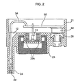
- FIG.2 shows the first embodiment of the sensor module unit according to the present invention as shown in FIG.1.
- the sensor module unit according to the first embodiment has three sensors, the intake-air temperature sensor 33, TPS 31, and intake-air pressure sensor 32.
- the sensor module unit is provided with the intake-air temperature sensor holding portion 24 installed with the intake-air temperature sensor, TPS holding portion 23A and intake-air pressure sensor holding portion 26 in respective predetermined positions in the unit main body 10.
- the intake-air temperature sensor holding portion 24 is comprised of the conduit 24 projecting to reach the inner wall of the throttle body 20 of the intake throttle apparatus 2 (FIG.1), and the conduit 24 is engaged in the opening 20A provided in the throttle body 20, whereby positioning in the vicinity of the throttle axis is carried out when the unit main body 10 is installed in the intake throttle apparatus 2.
- the intake-air temperature sensor 33 is positioned on the intake upstream side of the throttle valve 18, while the intake-air pressure sensor 32 is placed in a predetermined position on the intake downstream side of the throttle valve 18.
- the intake-air temperature sensor 33 is connected to the circuit substrate 30 through the lead 34, and the TPS 31 and intake-air pressure sensor 32 are directly mounted on the circuit substrate.
- the circuit substrate 30 is provided with the output signal adjusting means for converting output signals of these sensors into predetermined output signals.
- FIG.3 shows the second embodiment of the sensor module unit according to the present invention.
- the sensor module unit according to the second embodiment has four sensors, the intake-air temperature sensor 33, TPS 31, intake-air pressure sensor 32, and outside-air pressure sensor 35.
- the sensor module unit is provided with the intake-air temperature sensor holding portion 24 installed with the intake-air temperature sensor, TPS holding portion 23A, intake-air pressure sensor holding portion 26 and outside-air pressure sensor holding portion 36 in respective predetermined positions in the unit main body 10.
- outside-air pressure sensor 35 is installed so that the sensor surface faces upward to detect the air pressure outside the unit main body 10.
- the intake-air temperature sensor holding portion 24 is comprised of the conduit 24 projecting to reach the inner wall of the throttle body 20 of the intake throttle apparatus 2 (FIG.1), and the conduit 24 is engaged in the opening 20A provided in the throttle body 20, whereby positioning in the vicinity of the throttle axis is carried out when the unit main body 10 is installed in the intake throttle apparatus 2.
- the intake-air temperature sensor 33 is positioned on the intake upstream side of the throttle valve 18, while the intake-air pressure sensor 32 is placed in a predetermined position on the intake downstream side of the throttle valve 18.
- the outside-air pressure sensor 36 is arranged in the position for detecting the air pressure outside the unit main body 10.
- the intake-air temperature sensor 33 is connected to the circuit substrate 30 through the lead 34, and the TPS 31 and intake-air pressure sensor 32 are directly mounted on the circuit substrate.
- the circuit substrate 30 is provided with the output signal adjusting means for converting output signals of these sensors into predetermined output signals,
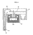
- FIG.4 shows the third embodiment of the sensor module unit according to the present invention.
- the sensor module unit according to the third embodiment has two sensors, the intake-air temperature sensor 33 and TPS 31.
- the sensor module unit is provided with the intake-air temperature sensor holding portion 24 installed with the intake-air temperature sensor and TPS holding portion 23A in respective predetermined positions in the unit main body 10.
- the intake-air temperature sensor holding portion 24 is comprised of the conduit 24 projecting to reach the inner wall of the throttle body 20 of the intake throttle apparatus 2 (FIG.1), and the conduit 24 is engaged in the opening 20A provided in the throttle body 20, whereby positioning in the vicinity of the throttle axis is carried out when the unit main body 10 is installed in the intake throttle apparatus 2.
- the intake-air temperature sensor 33 is positioned on the intake upstream side of the throttle valve 18.
- the intake-air temperature sensor 33 is connected to the circuit substrate 30 through the lead 34, and the TPS 31 is directly mounted on the circuit substrate.
- the circuit substrate 30 is provided with the output signal adjusting means for converting output signals of these sensors into predetermined output signals.
- FIG.5 shows the fourth embodiment of the sensor module unit according to the present invention.
- the sensor module unit according to the fourth embodiment has two sensors, the intake-air temperature sensor 33 and intake-air pressure sensor 32.
- the sensor module unit is provided with the intake-air temperature sensor holding portion 24 installed with the intake-air temperature sensor and intake-air pressure sensor holding portion 26 in respective predetermined positions in the unit main body 10.
- the intake-air temperature sensor holding portion 24 is comprised of the conduit 24 projecting to reach the inner wall of the throttle body 20 of the intake throttle apparatus 2 (FIG.1), and the conduit 24 is engaged in the opening 20A provided in the throttle body 20, whereby positioning in the vicinity of the throttle axis is carried out when the unit main body 10 is installed in the intake throttle apparatus 2.
- the intake-air temperature sensor 33 is positioned on the intake upstream side of the throttle valve 18, while the intake-air pressure sensor 32 is placed in a predetermined position on the intake downstream side of the throttle valve 18.
- the intake-air temperature sensor 33 is connected to the circuit substrate 30 through the lead 34, and the intake-air pressure sensor 32 is directly mounted on the circuit substrate.
- the circuit substrate 30 is provided with the output signal adjusting means for converting output signals of these sensors into predetermined output signals.
- FIG.6 shows a side view of the throttle apparatus 2 in which the sensor module unit 1 is installed, and thus shows a side-surface side of the throttle body 20 of the throttle apparatus 2 using a butterfly valve as the throttle valve of the throttle apparatus.
- the rotor 11 coupled to the throttle axis 15 to adjust the intake-air flow rate.
- the temperature sensor installation opening 12 to install the intake-air temperature sensor (see FIGS.2 to 5).
- the pressure measuring conduit 13 is formed on the intake downstream side (right side) of the rotor I 1 to measure a negative pressure rearward of the throttle valve.
- the temperature sensor installation opening 12 and pressure measuring conduit 13 are both communicated between the passage inside the throttle body 20 and outside. Further, for example, two screw holes 14 are provided to install the unit main body 10 (FIGs.2 to 5) so that the rotor 11 exists between the holes.
- the throttle body 20 is formed in the shape of a cylinder and provided with the air horn 10A at its left end and with the flange 10B at its right end.
- the rotor 11 coupled to the throttle axis (see FIG.1) is provided substantially in the center of the side surface of the throttle body 20.
- On the upstream side (left side) of the rotor 11 is formed the temperature sensor installation opening 12 to install the intake-air temperature sensor (see FIGS.2 to 5).
- the pressure measuring conduit 13 On the downstream side (right side) of the rotor 11 is formed the pressure measuring conduit 13 to measure a negative pressure rearward of the throttle valve.
- the temperature sensor installation opening 12 and pressure measuring conduit 13 are both communicated between the passage inside the throttle body 20 and outside.
- two screw holes 14 are provided to install the unit main body 10 so that the rotor 11 exists between the holes.
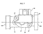
- FIG.7 shows the unit main body 10 installed in the throttle body 20 of FIG.6.
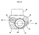
- FIG.8 shows a plan view of the unit main body 10 viewed from the side (back side) to be installed in the throttle body 20.
- the case 21 of the sensor main body as shown in FIG 7 stores the circuit substrate 30 (see FIGs.1 to 5) mounted with the intake-air temperature sensor 33, non-contact type TPS 31, intake-air pressure sensor 32, etc, and is sealed with a seal 22.
- the rotor 11 (FIG.6), temperature sensor installation opening 12, pressure measuring conduit 13, rotor engaging portion 23 in a position corresponding to each of the screw holes 14, temperature sensor conduit 24, pressure sensor holding portion 25 and two through holes 26.
- the rotor engaging portion 23 is formed of a cylindrical wall slightly larger than the rotor 11. Cylinder-shaped stator accommodating portion 23A is formed in the center inside the portion 23. The rotor 11 is engaged between the cylindrical wall of the rotor engaging portion 23 and stator accommodating portion 23A turnably.
- the temperature sensor conduit 24 projects vertically from the back side of the unit main body 10 and is provided at its front end with the temperature sensor (see FIGs.2 to 5). When installing the unit main body 10 in the throttle body 20, the temperature sensor conduit 24 is inserted into the temperature sensor installation opening 12. In this way, the unit main body 10 is positioned in the vicinity of the axis of the rotor engaging portion 23. In addition, the temperature sensor conduit 24 is configured to reach inside the throttle body 20 through the temperature sensor installation opening 12, and thus is prevented from being affected by heat of the throttle body.
- the pressure sensor holding portion 25 is arranged in the position in accordance with the pressure measuring conduit 13, and the pressure inside the throttle body 20 is guided to the pressure sensor holding portion 25. Finally, the unit main body 10 is fixed to the throttle body 20 with two screws 27. In other words, the screws 27 pass through two the through holes 26 provided in the unit main body 10 and fastened in the screw holes 14 provided on the side surface of the throttle body 20, respectively.
- the connector 28 is provided in the unit main body 10, and is connected to the electronic control circuit (not shown) through a signal cable (not shown).
- a plurality of terminals (not shown) are provided inside the connector 28 and connected to the circuit substrate provided inside the sensor circuit case 21.
- the electronic control circuit since the electronic control circuit has low resistance to heat, and therefore, is provided in a position spaced an adequate distance apart from the throttle body 20.
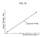
- FIG.9 is a block diagram schematically showing an electrical structure of the hall element 31, and FIG.10 is a graph showing the relationship between an angle of the throttle valve 18 and an output voltage of the hall element 31.
- the hall element 31 is configured as IC, and for example, is provided with a ground terminal GND, input terminal IN, and output terminal OUT.
- a hall voltage detecting circuit 310 to detect a hall voltage is provided in the hall element 31, and outputs a signal corresponding to variations in magnetic field in the vicinity.
- the signal output from the hall voltage detecting circuit 310 is converted into a digital signal via an A/D converter 311, input to a DSP (Digital Signal Processor) circuit 312, and given the predetermined digital signal processing.
- DSP Digital Signal Processor
- the signal is converted into an analog voltage signal via a D/A converter 313 and output from the output terminal OUT.
- the DSP circuit 312 is connected to EEPROM 314, and signal processing in the DSP circuit 312 is controlled based on parameters stored in the EEPROM 314. Data is written in the EEPROM 314 by inputting a pulse modulated signal (Vin) to the input terminal IN. In addition, inputting a predetermined signal disables rewrite of the EEPROM 314.
- a straight line L represents the relationship between angle ⁇ of the throttle valve 18 and voltage Vout output from the output terminal OUT.
- Values of coefficient C and offset voltage Vo can be written in EEPROM 314 as control parameters of the DSP circuit 312. In other words, output characteristics of the DSP circuit 312 are adjusted based on values of coefficient C and offset voltage Vo stored in the EEPROM 314.
- the coefficient C and offset voltage Vo that are control parameters of the DSP circuit 312 are written in the EEPROM 314, and the relationship between angle ⁇ of the throttle valve 18 and output Vout from the TPS is adjusted to be an appropriate relationship.
- the TPS and other sensors can be installed as an integrated unit in the throttle body, it is possible to facilitate the operation for installing these sensors in the throttle body and improve efficiency in the operation. Further, in this embodiment, since the relationship between an output of the TPS and angle of the throttle valve is adjusted electrically, the need is eliminated for performing a mechanical adjustment by temporary fastening unlike the conventional technique and the operation efficiency is drastically improved.
- the positional relationship between sensors is predetermined in the unit. Accordingly, in installation, it is necessary to position the unit in the throttle body so that each sensor is arranged in a suitable position.
- the suitable position of the TPS in the vicinity of the axis varies with each assembled product, it is necessary to perform a fine adjustment of the position of the TPS in the vicinity of the axis, and it is difficult to form the TPS and other sensors in an integrated manner.
- an electrical adjustment after installation substitutes for a relative fine adjustment of the TPS to the throttle valve in the rotation direction that is required to install the conventional TPS in the throttle body. In this way, the need is eliminated for performing the positioning of the TPS with high precision, and it is made possible to beforehand construct the TPS and sensors other than the TPS in an integrated unit with a simple structure.
- the temperature sensor conduit is also used to position the sensor unit, it is not necessary to separately provide a member for positioning.
- this embodiment describes the non-contact type TPS using a hall element as an example, but it may be possible to use a sensor using an MR element other than the hall element or an inductive type sensor.
- this embodiment describes the non-contact type TPS, intake-air pressure sensor and outside-air pressure sensor besides the intake-air temperature sensor, but the present invention is not limited to these sensors. Furthermore, the unit may be provided with a plurality of other sensors at the same time.
- the intake-air temperature sensor conduit is used as a guide of the positioning, but the intake-air pressure sensor holding portion or the like may be used as a guide of the positioning.
- the present invention relates to a sensor module unit provided with a plurality of sensors that facilitates installation and adjustment subsequent to the installation of sensors to detect various kinds of data indispensable to fuel supply control and intake-air flow rate control of an internal-combustion engine, and has industrially applicability.
Landscapes
- Engineering & Computer Science (AREA)
- General Engineering & Computer Science (AREA)
- Mechanical Engineering (AREA)
- Chemical & Material Sciences (AREA)
- Combustion & Propulsion (AREA)
- Control Of Throttle Valves Provided In The Intake System Or In The Exhaust System (AREA)
- Combined Controls Of Internal Combustion Engines (AREA)
Abstract
Description
Claims (12)
- A sensor module unit integrally provided with a plurality of sensors necessary for fuel supply control and intake-air flow rate control in an internal-combustion engine, comprising:wherein each of the plurality of sensors is positioned in a predetermined measuring position in the throttle apparatus when the unit main body is installed in the vicinity of a throttle axis of the intake throttle apparatus.an intake-air temperature sensor holding portion installed with an intake-air temperature sensor; at least one of a throttle position sensor holding portion installed with a position sensor to detect an opening angle of a throttle valve in an intake throttle apparatus and an intake-air pressure sensor holding portion installed with an intake-air pressure sensor; anda unit main body that integrally accommodates the intake-air temperature sensor holding portion, and at least one of the throttle position sensor holding portion and the intake-air pressure sensor holding portion to position in respective predetermined arrangement positions in the unit,
- The sensor module unit according to claim 1, wherein when the unit main body is installed in the intake throttle apparatus, the intake-air temperature sensor is positioned on an intake upstream side of the throttle valve, while the intake-air pressure sensor is positioned on an intake downstream side of the throttle valve if the unit has the intake-air pressure sensor holding portion.
- The sensor module unit according to claim 1, further comprising:an outside-air pressure sensor holding portion installed with an outside-air pressure sensor in a position adjacent to the intake-air temperature sensor holding portion in the unit main body, substituting for or together with the intake-air pressure sensor holding portion.
- The sensor module unit according to claim 3, wherein the outside-air pressure sensor is arranged on the intake upstream side of the throttle valve, when the unit main body is installed in the intake throttle apparatus.
- The sensor module unit according to any one of claims 1 to 4, wherein the temperature sensor holding portion determines positioning in the vicinity of the throttle axis, when the unit main body is installed in the intake throttle apparatus.
- The sensor module unit according to claim 5, wherein the temperature sensor holding portion is a conduit projecting to reach an inner wall of a throttle body of the intake throttle apparatus, and the positioning is carried out by the conduit being engaged in an opening provided in the throttle body.
- The sensor module unit according to claim 1, wherein the throttle position sensor is a non-contact type position sensor such as a hall element and an MR element to detect an opening angle of the throttle valve.
- The sensor module unit according to claim 7, further comprising:wherein the circuit substrate has output signal adjusting means for converting at least a sensor output from the non-contact type position sensor into a predetermined output signal.a circuit substrate to which are connected sensor output lines from the plurality of sensors,
- The sensor module unit according to claim 7, wherein the circuit substrate is provided with interface means for transmitting outputs of the plurality of sensors or the output signal to an external electronic fuel injection control apparatus having an intake throttle valve control apparatus or intake throttle control apparatus.
- An intake throttle valve control apparatus including the sensor module unit according to any one of claims 1 to 9.
- An intake throttle apparatus having the intake throttle control apparatus according to claim 10.
- A vehicle provided with the intake throttle apparatus according to claim 11.
Applications Claiming Priority (3)
| Application Number | Priority Date | Filing Date | Title |
|---|---|---|---|
| JP2003043116 | 2003-02-20 | ||
| JP2003043116 | 2003-02-20 | ||
| PCT/JP2004/001778 WO2004074661A1 (en) | 2003-02-20 | 2004-02-18 | Sensor module unit and throttle device with the same |
Publications (2)
| Publication Number | Publication Date |
|---|---|
| EP1605149A1 true EP1605149A1 (en) | 2005-12-14 |
| EP1605149A4 EP1605149A4 (en) | 2009-04-22 |
Family
ID=32905387
Family Applications (1)
| Application Number | Title | Priority Date | Filing Date |
|---|---|---|---|
| EP04712155A Withdrawn EP1605149A4 (en) | 2003-02-20 | 2004-02-18 | SENSOR MODULE UNIT AND BUTTERFLY DEVICE HAVING THE SAME |
Country Status (8)
| Country | Link |
|---|---|
| US (1) | US7305966B2 (en) |
| EP (1) | EP1605149A4 (en) |
| JP (1) | JP4509025B2 (en) |
| KR (1) | KR101103400B1 (en) |
| CN (1) | CN100392221C (en) |
| BR (1) | BRPI0407602B8 (en) |
| TW (1) | TW200422514A (en) |
| WO (1) | WO2004074661A1 (en) |
Cited By (6)
| Publication number | Priority date | Publication date | Assignee | Title |
|---|---|---|---|---|
| WO2010145877A1 (en) * | 2009-06-15 | 2010-12-23 | Robert Bosch Gmbh | Combination sensor |
| WO2012028385A1 (en) * | 2010-08-31 | 2012-03-08 | Robert Bosch Gmbh | Combination sensor |
| CN105716890A (en) * | 2015-12-30 | 2016-06-29 | 东莞市青麦田数码科技有限公司 | Airplane temperature compensator test system and test method |
| EP2977593A4 (en) * | 2013-03-21 | 2017-01-25 | Keihin Corporation | Air intake device for engine for two-wheeled motor vehicle |
| EP2047080B1 (en) * | 2006-08-01 | 2017-03-29 | PC/RC Products L.L.C. | Small engine operation components |
| DE102015110379B4 (en) * | 2014-08-26 | 2021-05-12 | Kwang Yang Motor Co., Ltd. | Throttle valve unit for an internal combustion engine |
Families Citing this family (33)
| Publication number | Priority date | Publication date | Assignee | Title |
|---|---|---|---|---|
| JP4512007B2 (en) * | 2005-08-02 | 2010-07-28 | 株式会社ケーヒン | Intake negative pressure detection device in throttle body |
| CN100365261C (en) * | 2005-09-28 | 2008-01-30 | 联合汽车电子有限公司 | Module of gas saving valve for mini engine |
| WO2007052554A1 (en) * | 2005-11-07 | 2007-05-10 | Keihin Corporation | Air intake device for engine |
| KR100767504B1 (en) * | 2006-04-10 | 2007-10-17 | 말레동현필터시스템 주식회사 | Automotive manifold valve monitoring device |
| JP4954786B2 (en) * | 2007-05-09 | 2012-06-20 | 株式会社ニッキ | Throttle device with built-in electronic control means |
| JP4416012B2 (en) * | 2007-06-06 | 2010-02-17 | 株式会社日立製作所 | Intake air flow rate measuring device |
| CN101363368B (en) * | 2008-06-18 | 2011-12-14 | 绍兴平国电子科技有限公司 | Integration unit of air control shutter and controller and method for manufacturing same |
| KR101018428B1 (en) * | 2009-01-21 | 2011-03-02 | 캄텍주식회사 | Non-contact throttle position sensor |
| JP5212488B2 (en) * | 2011-01-13 | 2013-06-19 | 株式会社デンソー | Sensor module |
| DE102011004447A1 (en) * | 2011-02-21 | 2012-08-23 | Robert Bosch Gmbh | Sensor unit for a vehicle |
| CN103016210B (en) * | 2011-09-28 | 2015-12-09 | 湖南省力宇燃气动力有限公司 | A kind of gas-engine mixer |
| CN202300672U (en) * | 2011-10-26 | 2012-07-04 | 德尔福(上海)动力推进系统有限公司 | Electric spraying control device integrated with air inlet pressure sensor |
| CN202300671U (en) * | 2011-10-26 | 2012-07-04 | 德尔福(上海)动力推进系统有限公司 | Electric injection control device integrating throttle valve position sensor |
| JP5943007B2 (en) * | 2014-01-14 | 2016-06-29 | 株式会社デンソー | Sensor module |
| FR3019256B1 (en) * | 2014-04-01 | 2017-02-24 | Valeo Systemes De Controle Moteur | ACTUATING DEVICE OF A VALVE |
| CN104154950B (en) * | 2014-07-11 | 2017-06-16 | 北京联创思源测控技术有限公司 | Combined type pressure flow sensor |
| TWI611099B (en) * | 2015-05-13 | 2018-01-11 | 光陽工業股份有限公司 | Engine throttle body construction |
| TWI554678B (en) * | 2015-12-01 | 2016-10-21 | Kwang Yang Motor Co | Engine throttle body structure |
| CN106870168B (en) * | 2015-12-10 | 2020-09-11 | 光阳工业股份有限公司 | Engine throttle body structure |
| CN105333207B (en) * | 2015-12-11 | 2018-08-24 | 中国航空工业集团公司西安飞机设计研究所 | A kind of bleed valve based on flow-rate adjustment |
| DE102016109495B4 (en) * | 2016-05-24 | 2025-12-31 | VAG GmbH | Venting and/or air release valve |
| CN105784009B (en) * | 2016-05-25 | 2018-01-02 | 芜湖力锐达汽车部件有限公司 | A kind of motorcycle positions air inlet temperature/pressure sensor |
| IT201700060141A1 (en) * | 2017-06-01 | 2018-12-01 | Magneti Marelli Spa | BUTTERFLY VALVE FOR AN INTERNAL COMBUSTION ENGINE WITH A PRESSURE SENSOR AND A TEMPERATURE SENSOR |
| IT201800000948A1 (en) * | 2018-01-15 | 2019-07-15 | Magneti Marelli Spa | MECHATRONIC DEVICE FOR AN INTERNAL COMBUSTION ENGINE FITTED WITH AN INTEGRATED TEMPERATURE AND PRESSURE SENSOR |
| KR102050914B1 (en) * | 2018-08-23 | 2019-12-02 | 주식회사 현대케피코 | Electronic throttle valve apparatus |
| JP2022017602A (en) | 2018-10-11 | 2022-01-26 | ヤマハ発動機株式会社 | Throttle body assembly for single combustion chamber |
| CN111207927A (en) * | 2018-11-21 | 2020-05-29 | 中国船舶重工集团公司第七一一研究所 | Parameter monitoring device for valve drive mechanism of internal combustion engine and valve drive mechanism |
| JP2020112089A (en) * | 2019-01-11 | 2020-07-27 | 株式会社ニッキ | Electronically controlled throttle device for internal combustion engine |
| CN112856017B (en) * | 2019-11-11 | 2024-01-23 | 盾安环境技术有限公司 | Valve |
| JP7320473B2 (en) * | 2020-03-27 | 2023-08-03 | Ckd株式会社 | butterfly valve |
| US20230259113A1 (en) * | 2022-02-11 | 2023-08-17 | Novity, Inc. | Subsystem-level model-based diagnosis |
| CN115163847B (en) * | 2022-09-05 | 2023-03-31 | 泰伦机械(苏州)有限公司 | Throttle valve convenient to install |
| KR102759871B1 (en) * | 2023-08-31 | 2025-01-23 | 주식회사 현대케피코 | Electronic throttle valve apparatus |
Family Cites Families (18)
| Publication number | Priority date | Publication date | Assignee | Title |
|---|---|---|---|---|
| JPH02256865A (en) * | 1989-03-28 | 1990-10-17 | Honda Motor Co Ltd | Mixture gas control device for fuel injection engine |
| JPH07260534A (en) | 1994-03-17 | 1995-10-13 | Hitachi Ltd | Air flow measuring device |
| US5711271A (en) * | 1995-05-05 | 1998-01-27 | Robert Bosch Gmbh | Throttle apparatus for an internal combustion engine |
| JPH09250374A (en) | 1996-03-12 | 1997-09-22 | Mitsubishi Motors Corp | Sensor integrated throttle body |
| DE19728349A1 (en) * | 1997-07-03 | 1999-01-07 | Telefunken Microelectron | Sensor arrangement and engine control device for an internal combustion engine |
| JP3585362B2 (en) | 1998-02-05 | 2004-11-04 | アルプス電気株式会社 | Sensor and sensor manufacturing method |
| JPH11294216A (en) * | 1998-04-14 | 1999-10-26 | Yamaha Motor Co Ltd | Engine control device |
| US6725833B1 (en) * | 1999-03-29 | 2004-04-27 | Hitachi, Ltd. | Electronically controlled throttle device |
| JP4414027B2 (en) * | 1999-09-03 | 2010-02-10 | 本田技研工業株式会社 | Engine intake system |
| JP2001207867A (en) | 2000-01-25 | 2001-08-03 | Denso Corp | Electronically controlled fuel injector |
| JP2001214776A (en) * | 2000-02-03 | 2001-08-10 | Hitachi Ltd | Automotive control device |
| EP1128168A3 (en) | 2000-02-23 | 2002-07-03 | Hitachi, Ltd. | Measurement apparatus for measuring physical quantity such as fluid flow |
| JP3825267B2 (en) * | 2000-02-23 | 2006-09-27 | 株式会社日立製作所 | Flow measurement device, physical detection device, and engine system |
| JP3866899B2 (en) * | 2000-04-06 | 2007-01-10 | 株式会社日立製作所 | Throttle valve control device for internal combustion engine and automobile |
| DE60135245D1 (en) * | 2000-11-30 | 2008-09-18 | Keihin Corp | |
| JP3986850B2 (en) * | 2001-04-27 | 2007-10-03 | 株式会社ケーヒン | Engine intake air amount control device |
| JP4464581B2 (en) * | 2001-05-24 | 2010-05-19 | 本田技研工業株式会社 | Engine intake air amount control device |
| DE10133294A1 (en) | 2001-07-12 | 2003-01-23 | Siemens Ag | throttle body |
-
2004
- 2004-02-18 WO PCT/JP2004/001778 patent/WO2004074661A1/en not_active Ceased
- 2004-02-18 CN CNB2004800045308A patent/CN100392221C/en not_active Expired - Fee Related
- 2004-02-18 EP EP04712155A patent/EP1605149A4/en not_active Withdrawn
- 2004-02-18 US US10/546,326 patent/US7305966B2/en not_active Expired - Lifetime
- 2004-02-18 JP JP2005502727A patent/JP4509025B2/en not_active Expired - Fee Related
- 2004-02-18 TW TW093103928A patent/TW200422514A/en not_active IP Right Cessation
- 2004-02-18 KR KR1020057015157A patent/KR101103400B1/en not_active Expired - Fee Related
- 2004-02-18 BR BRPI0407602A patent/BRPI0407602B8/en not_active IP Right Cessation
Cited By (6)
| Publication number | Priority date | Publication date | Assignee | Title |
|---|---|---|---|---|
| EP2047080B1 (en) * | 2006-08-01 | 2017-03-29 | PC/RC Products L.L.C. | Small engine operation components |
| WO2010145877A1 (en) * | 2009-06-15 | 2010-12-23 | Robert Bosch Gmbh | Combination sensor |
| WO2012028385A1 (en) * | 2010-08-31 | 2012-03-08 | Robert Bosch Gmbh | Combination sensor |
| EP2977593A4 (en) * | 2013-03-21 | 2017-01-25 | Keihin Corporation | Air intake device for engine for two-wheeled motor vehicle |
| DE102015110379B4 (en) * | 2014-08-26 | 2021-05-12 | Kwang Yang Motor Co., Ltd. | Throttle valve unit for an internal combustion engine |
| CN105716890A (en) * | 2015-12-30 | 2016-06-29 | 东莞市青麦田数码科技有限公司 | Airplane temperature compensator test system and test method |
Also Published As
| Publication number | Publication date |
|---|---|
| BRPI0407602A (en) | 2006-02-14 |
| TW200422514A (en) | 2004-11-01 |
| BRPI0407602B8 (en) | 2019-10-01 |
| KR101103400B1 (en) | 2012-01-05 |
| BRPI0407602B1 (en) | 2019-09-03 |
| JP4509025B2 (en) | 2010-07-21 |
| US7305966B2 (en) | 2007-12-11 |
| KR20050098947A (en) | 2005-10-12 |
| US20060231073A1 (en) | 2006-10-19 |
| CN1751176A (en) | 2006-03-22 |
| WO2004074661A1 (en) | 2004-09-02 |
| TWI319044B (en) | 2010-01-01 |
| JPWO2004074661A1 (en) | 2006-06-01 |
| EP1605149A4 (en) | 2009-04-22 |
| CN100392221C (en) | 2008-06-04 |
Similar Documents
| Publication | Publication Date | Title |
|---|---|---|
| US7305966B2 (en) | Sensor module unit and a throttle apparatus equipped with the sensor module unit | |
| US7934419B2 (en) | Intake air mass flow measurement device | |
| KR100415204B1 (en) | Internal Combustion Engine | |
| US8736261B2 (en) | Sensor module | |
| EP2143914B1 (en) | Throttle apparatus and motorcycle having the same | |
| JP2017044598A (en) | Air flow measurement device | |
| EP1929148B1 (en) | Variable reluctance position sensor | |
| KR20060073968A (en) | Intake device, sensor unit, motorcycle and intake temperature detection method | |
| US7779809B2 (en) | Throttle system and sensor unit | |
| KR20010041056A (en) | Control system for internal combustion engine comprising a sensor and an interface for digitising measurement values | |
| DE102012221697A1 (en) | Engine control unit | |
| JP2001234761A (en) | Module and intake device for internal combustion engine | |
| JP2009085855A (en) | Flow rate measuring device and control system for internal combustion engine | |
| EP4060293B1 (en) | Physical quantity detection device | |
| EP2354497A1 (en) | Air delivery device for internal combustion engines | |
| JP2007270617A (en) | Sensor module unit and throttle system | |
| JP2004332633A (en) | Throttle control device | |
| JP2001248462A (en) | Engine electric intake air amount control device | |
| JPH07293403A (en) | Sensor integrated engine controller | |
| JP2007270618A (en) | Sensor unit and throttle system | |
| WO2005116428A1 (en) | Throttle system and sensor unit | |
| KR19980046187A (en) | Air flow meter |
Legal Events
| Date | Code | Title | Description |
|---|---|---|---|
| PUAI | Public reference made under article 153(3) epc to a published international application that has entered the european phase |
Free format text: ORIGINAL CODE: 0009012 |
|
| 17P | Request for examination filed |
Effective date: 20050913 |
|
| AK | Designated contracting states |
Kind code of ref document: A1 Designated state(s): AT BE BG CH CY CZ DE DK EE ES FI FR GB GR HU IE IT LI LU MC NL PT RO SE SI SK TR |
|
| AX | Request for extension of the european patent |
Extension state: AL LT LV MK |
|
| DAX | Request for extension of the european patent (deleted) | ||
| RBV | Designated contracting states (corrected) |
Designated state(s): DE FR GB IT |
|
| A4 | Supplementary search report drawn up and despatched |
Effective date: 20090320 |
|
| RIC1 | Information provided on ipc code assigned before grant |
Ipc: F16K 37/00 20060101ALI20090316BHEP Ipc: F02D 11/10 20060101ALI20090316BHEP Ipc: F02D 9/10 20060101AFI20090316BHEP |
|
| 17Q | First examination report despatched |
Effective date: 20090605 |
|
| STAA | Information on the status of an ep patent application or granted ep patent |
Free format text: STATUS: THE APPLICATION IS DEEMED TO BE WITHDRAWN |
|
| 18D | Application deemed to be withdrawn |
Effective date: 20120829 |
|
| R18D | Application deemed to be withdrawn (corrected) |
Effective date: 20120901 |