EP1605074A1 - Thermal recovery treatment for a service-degraded component of a gas turbine - Google Patents
Thermal recovery treatment for a service-degraded component of a gas turbine Download PDFInfo
- Publication number
- EP1605074A1 EP1605074A1 EP05011190A EP05011190A EP1605074A1 EP 1605074 A1 EP1605074 A1 EP 1605074A1 EP 05011190 A EP05011190 A EP 05011190A EP 05011190 A EP05011190 A EP 05011190A EP 1605074 A1 EP1605074 A1 EP 1605074A1
- Authority
- EP
- European Patent Office
- Prior art keywords
- heat treatment
- component
- temperature
- refurbishing
- pressure
- Prior art date
- Legal status (The legal status is an assumption and is not a legal conclusion. Google has not performed a legal analysis and makes no representation as to the accuracy of the status listed.)
- Granted
Links
Images




Classifications
-
- B—PERFORMING OPERATIONS; TRANSPORTING
- B23—MACHINE TOOLS; METAL-WORKING NOT OTHERWISE PROVIDED FOR
- B23P—METAL-WORKING NOT OTHERWISE PROVIDED FOR; COMBINED OPERATIONS; UNIVERSAL MACHINE TOOLS
- B23P6/00—Restoring or reconditioning objects
- B23P6/002—Repairing turbine components, e.g. moving or stationary blades, rotors
-
- C—CHEMISTRY; METALLURGY
- C22—METALLURGY; FERROUS OR NON-FERROUS ALLOYS; TREATMENT OF ALLOYS OR NON-FERROUS METALS
- C22F—CHANGING THE PHYSICAL STRUCTURE OF NON-FERROUS METALS AND NON-FERROUS ALLOYS
- C22F1/00—Changing the physical structure of non-ferrous metals or alloys by heat treatment or by hot or cold working
- C22F1/02—Changing the physical structure of non-ferrous metals or alloys by heat treatment or by hot or cold working in inert or controlled atmosphere or vacuum
-
- C—CHEMISTRY; METALLURGY
- C22—METALLURGY; FERROUS OR NON-FERROUS ALLOYS; TREATMENT OF ALLOYS OR NON-FERROUS METALS
- C22F—CHANGING THE PHYSICAL STRUCTURE OF NON-FERROUS METALS AND NON-FERROUS ALLOYS
- C22F1/00—Changing the physical structure of non-ferrous metals or alloys by heat treatment or by hot or cold working
- C22F1/10—Changing the physical structure of non-ferrous metals or alloys by heat treatment or by hot or cold working of nickel or cobalt or alloys based thereon
-
- C—CHEMISTRY; METALLURGY
- C23—COATING METALLIC MATERIAL; COATING MATERIAL WITH METALLIC MATERIAL; CHEMICAL SURFACE TREATMENT; DIFFUSION TREATMENT OF METALLIC MATERIAL; COATING BY VACUUM EVAPORATION, BY SPUTTERING, BY ION IMPLANTATION OR BY CHEMICAL VAPOUR DEPOSITION, IN GENERAL; INHIBITING CORROSION OF METALLIC MATERIAL OR INCRUSTATION IN GENERAL
- C23C—COATING METALLIC MATERIAL; COATING MATERIAL WITH METALLIC MATERIAL; SURFACE TREATMENT OF METALLIC MATERIAL BY DIFFUSION INTO THE SURFACE, BY CHEMICAL CONVERSION OR SUBSTITUTION; COATING BY VACUUM EVAPORATION, BY SPUTTERING, BY ION IMPLANTATION OR BY CHEMICAL VAPOUR DEPOSITION, IN GENERAL
- C23C4/00—Coating by spraying the coating material in the molten state, e.g. by flame, plasma or electric discharge
- C23C4/02—Pretreatment of the material to be coated, e.g. for coating on selected surface areas
-
- F—MECHANICAL ENGINEERING; LIGHTING; HEATING; WEAPONS; BLASTING
- F01—MACHINES OR ENGINES IN GENERAL; ENGINE PLANTS IN GENERAL; STEAM ENGINES
- F01D—NON-POSITIVE DISPLACEMENT MACHINES OR ENGINES, e.g. STEAM TURBINES
- F01D5/00—Blades; Blade-carrying members; Heating, heat-insulating, cooling or antivibration means on the blades or the members
- F01D5/12—Blades
- F01D5/28—Selecting particular materials; Particular measures relating thereto; Measures against erosion or corrosion
- F01D5/286—Particular treatment of blades, e.g. to increase durability or resistance against corrosion or erosion
-
- C—CHEMISTRY; METALLURGY
- C21—METALLURGY OF IRON
- C21D—MODIFYING THE PHYSICAL STRUCTURE OF FERROUS METALS; GENERAL DEVICES FOR HEAT TREATMENT OF FERROUS OR NON-FERROUS METALS OR ALLOYS; MAKING METAL MALLEABLE, e.g. BY DECARBURISATION OR TEMPERING
- C21D9/00—Heat treatment, e.g. annealing, hardening, quenching or tempering, adapted for particular articles; Furnaces therefor
- C21D9/0068—Heat treatment, e.g. annealing, hardening, quenching or tempering, adapted for particular articles; Furnaces therefor for particular articles not mentioned below
-
- F—MECHANICAL ENGINEERING; LIGHTING; HEATING; WEAPONS; BLASTING
- F05—INDEXING SCHEMES RELATING TO ENGINES OR PUMPS IN VARIOUS SUBCLASSES OF CLASSES F01-F04
- F05D—INDEXING SCHEME FOR ASPECTS RELATING TO NON-POSITIVE-DISPLACEMENT MACHINES OR ENGINES, GAS-TURBINES OR JET-PROPULSION PLANTS
- F05D2230/00—Manufacture
- F05D2230/80—Repairing, retrofitting or upgrading methods
-
- F—MECHANICAL ENGINEERING; LIGHTING; HEATING; WEAPONS; BLASTING
- F05—INDEXING SCHEMES RELATING TO ENGINES OR PUMPS IN VARIOUS SUBCLASSES OF CLASSES F01-F04
- F05D—INDEXING SCHEME FOR ASPECTS RELATING TO NON-POSITIVE-DISPLACEMENT MACHINES OR ENGINES, GAS-TURBINES OR JET-PROPULSION PLANTS
- F05D2230/00—Manufacture
- F05D2230/90—Coating; Surface treatment
-
- Y—GENERAL TAGGING OF NEW TECHNOLOGICAL DEVELOPMENTS; GENERAL TAGGING OF CROSS-SECTIONAL TECHNOLOGIES SPANNING OVER SEVERAL SECTIONS OF THE IPC; TECHNICAL SUBJECTS COVERED BY FORMER USPC CROSS-REFERENCE ART COLLECTIONS [XRACs] AND DIGESTS
- Y02—TECHNOLOGIES OR APPLICATIONS FOR MITIGATION OR ADAPTATION AGAINST CLIMATE CHANGE
- Y02T—CLIMATE CHANGE MITIGATION TECHNOLOGIES RELATED TO TRANSPORTATION
- Y02T50/00—Aeronautics or air transport
- Y02T50/60—Efficient propulsion technologies, e.g. for aircraft
-
- Y—GENERAL TAGGING OF NEW TECHNOLOGICAL DEVELOPMENTS; GENERAL TAGGING OF CROSS-SECTIONAL TECHNOLOGIES SPANNING OVER SEVERAL SECTIONS OF THE IPC; TECHNICAL SUBJECTS COVERED BY FORMER USPC CROSS-REFERENCE ART COLLECTIONS [XRACs] AND DIGESTS
- Y10—TECHNICAL SUBJECTS COVERED BY FORMER USPC
- Y10T—TECHNICAL SUBJECTS COVERED BY FORMER US CLASSIFICATION
- Y10T29/00—Metal working
- Y10T29/49—Method of mechanical manufacture
- Y10T29/49316—Impeller making
- Y10T29/49318—Repairing or disassembling
Definitions
- This invention relates to a method for refurbishing service degraded gas turbine components, and, in particular, a refurbishing process using Hot Iso-static Press (HIP) method.
- HIP Hot Iso-static Press
- compressed air from a compressor which is provided coaxially with a gas turbine, is introduced into a combustor together with fuel.
- High temperature combustion gas which is caused by combustion of the fuel with the compressed air in the combustor, is introduced to turbine blades via transition pieces and turbine nozzles.
- the combustion gas drives turbine blades of the gas turbine to produce work to drive a generator, which is coupled to the gas turbine.
- a heat resistant superalloy is applied to one or more components of the gas turbine, such as a combustion liner, a transition piece, a turbine blade or a turbine nozzle, which are exposed to the high temperature in the gas turbine.
- a nickel base superalloy is used for the turbine blade, where high temperature strength is especially needed.
- the nickel base superalloy is a precipitation strengthening type alloy, and its high temperature strength is achieved by precipitation of intermetallic compound of Ni 3 (Ai, Ti), which is referred to as " ⁇ " phase", in a nickel matrix.
- the nickel base superalloy has high heat resistance, however, various damages or defects (referred to as “damages”) may be observed in the nickel base superalloy after the gas turbine has been operated for certain period. This damage is caused by degradation of the material, erosion, corrosion or oxidization, which is more likely to occur for the gas turbine component such as turbine blade in the high temperature environment, in which the gas turbine components are exposed. Further, creep damages accumulate in the turbine blade due to centrifugal stress caused by the operation of the gas turbine. When the gas turbine plant starts or stops operating, further damages accumulate in the gas turbine blade by the thermal fatigues due to the change of temperature in addition to the centrifugal stress.
- a turbine blade is scrapped when it reaches its design life.
- a turbine blade for the first stage of the 1,100 degrees centigrade class gas turbine operated for the base-load purpose having an oxidation-resistant and corrosion-resistant coating on its surface has 48,000 hours until it is scrapped.
- the turbine blade is re-coated, such re-coating of the oxidation-resistant and corrosion resistant coating is carried out after 24,000 hours operation of the turbine blade. In that case, the re-coated turbine blade is used for 48,000 hours after the re-coating and is then scrapped.
- the turbine blade is heat-treated; however, this heat treatment is not intended to refurbish the base metal of the turbine blade.
- turbine components exposed to the high temperature such as the turbine nozzle, the combustion liner or the transition piece, are repaired by welding when a crack or an abrasion is found. These turbine components are used again after being repaired. When being repaired, these components are heat-treated to reduce the heat effect caused by welding or residual stress, if it is necessary.
- the temperature of combustion gas introduced to gas turbine is becoming higher to improve the thermal efficiency.
- the nickel base superalloy which is used for turbine blade, is starting to be applied to the turbine nozzle, the combustion liner or the transition piece. It is generally known that the nickel base superalloy is difficult to repair or refurbish.
- a conventional refurbishment technology for restoration of casting defects of the precision casting is described in the Japanese Patent Publication (Kokai) No. 57-207163.
- This technology is substantially a HIP process, which compresses defects such as creep voidsand dislocations.
- This publication describes a technique to perform heat treatment in a wide and general range of temperature (more than a temperature from 600 to 950 degrees centigrade) such as in a range of more than 50%, in a range of 60 to 95%, and in a range of 80-95% of melting point of the component (which is more than 1,000 degrees centigrade).
- Japanese Patent Publication (Kokai) No. 51-151253 discloses a technology to remove small defects referred to as "creep voids" caused by creep in a metal component which has been used in the high temperature environment.
- heat treatment is performed in a wide range of temperature, such as, 980 to 1232 degrees centigrade. This range covers the temperature from less than the solvus temperature of the ⁇ ' phase to the highest temperature of the beginning of the incipient melting, and is not related with recovering of the ⁇ ' phase.
- Japanese Patent Publication (Kokai) No. 57-62884 discloses a technology that removes micro defects which are included inside the weld by HIP process after welding.
- heat treatment temperature range which is disclosed as from about 1,000 to 1250 degrees centigrade, is also wide to cover the temperature from less than the solvus temperature of the ⁇ ' phase to the highest temperature of the beginning of the incipient melting. This temperature range is not related with recovering of the ⁇ ' phase.
- Japanese Patent Publication (Kokai) No. 51-14131 discloses a uniformizing technology that eliminates an opening such as relatively large crack, a crevice or a large hole included in a casting just after its casting process.
- Japanese Patent Publication (Kokai) No. 55-113833 discloses a technology applying solution heat treatment in addition to the HIP process to compress voids inside the casting.
- Japanese Patent (Kokoku) No. 4-6789 and Japanese Patent Publication (Kokai) No. 2000-80455 disclose technologies of recovering life using heat treatment that recovers the microstructure of the alloy by elevating the temperature to the dissolving temperature of the ⁇ ' phase, which constitutes coarsened main strengthening phase.
- the incipient melting temperature and the solvus temperature of the ⁇ ' phase are close to each other, the strength is reduced due to the incipient melting or the recrystallization. Further, the internal damage(defect) such as the creep void due to the operation cannot be eliminated with this process.
- an element that cause decline of the melting point tends to segregate along the dendrite boundary. Particularly, around the area where these elements extremely segregate along the dendrite boundary, the melting point is also extremely declined. In this case, the melting point of the area becomes close to the solving temperature of the ⁇ ' phases, which are main precipitation strengthening phases. Therefore, these materials are usually heat-treated in the range of temperature that can make appropriate microstructure without causing incipient melting. Hence, it is difficult to recover the microstructure by re-precipitation of the ⁇ ' phases, which are main precipitation strengthening phases, after its full solution. Rather, in some situations, it reduces strength or life of the component by further agglomerating ⁇ ' phases that have already coarsened by use of the component.
- Japanese Patent Publication (Kokai) No. 11-335802 discloses recovering technology that applies a recovery heat treatment process under high pressure environment using HIP process to restore inner defects and recover areas that have incipient melting before applying the solution heat treatment and the aging heat treatment, which are applied in a non-pressurized environment.
- grain boundary strengthening elements such as B, Zr, Hf or C are added to the alloy. These elements segregate along the dendrite boundary during solidification process of alloy. This makes the temperature of incipient melting almost equivalent or less than the temperature of the solvus temperature of the ⁇ ' phases.
- the recovery heat treatment When the recovery heat treatment is applied to this alloy in the temperature higher than the solvus temperature of the ⁇ ' phases, the ⁇ ' phases can be fullly dissolved in the base metal, which is the ⁇ phases. Since the recovery heat treatment process is applied in the high pressure environment, the pressure closes incipient melting areas even if the incipient meltings occur. Therefore, this technology enables to recover the alloy of the gas turbine component without reduction of the strength due to the incipient melting.
- the refurbished gas turbine components according to this technology can obtain life and property equivalent, or even greater than, compared to the time of its manufacture. However, in this technology, because the incipient melting area crystallizes and becomes fine grains during its solidification process, the recovering process may not be completed. Thus, recovery of the alloy according to this technology depends on the extent of the incipient melting.
- an advantage of an aspect of the present invention is to provide a method for refurbishing service-degraded gas turbine component that can recover the microstructure of the alloy of the gas turbine component, whose material is deteriorated or damaged after its operation, to the extent that is equivalent or more than the characteristic at the time of its manufacture, which has microstructure with full solution of the ⁇ ' phases without the defect due to the incipient melting.
- one aspect of the present invention is to provide a method for refurbishing a service-degraded component of a precipitation strengthening type of alloy for a gas turbine that comprises performing a recovery heat treatment on the component in an environment having a predetermined pressure that is greater than atmospheric pressure, wherein the temperature of the component is increased to a predetermined temperature in the environment having the predetermined pressure; performing a solution heat treatment, which is processed under reduced pressure or inert gas atmosphere, the solution heat treatment being performed after performing the recovery heat treatment, and performing an aging heat treatment, which is processed under reduced pressure or an inert gas atmosphere, the aging heat treatment being performed after performing the recovery heat treatment.
- One aspect of the embodiments according to the present invention is increasing the temperature of the component to a predetermined recovery heat treatment temperature under high pressure environment. This can avoid depression of the incipient melting temperature due to the segregation of the grain boundary strengthening elements, such as B, Zr, Hf and C, or other impurity elements that are inevitability contained such as Pb, Sn and Zn, along the dendrite boundaries. Furthermore, the alloy of the component is recovered without the incipient melting by solving the ⁇ ' phases at lower temperature, since the solid solution of the ⁇ ' phases is facilitated due to an acceleration of diffusion of elements which form the ⁇ ' phases such as Al and Ti.
- the refurbished component according this process can obtain life and characteristic, which are equivalent or greater than those of newly manufactured components, without dispersion.
- elevation of the melting point, which is equivalent to the incipient melting temperature, in the high pressure environment is observed in an element that has larger thermal expansion coefficient.
- the melting point of Pb in the environment of the normal pressure is about 600K, whereas it is known that the melting point goes up by 200K in the environment of 500,000MPa.
- Fig. 1 is a flow chart of the refurbishing method in accordance with the first embodiment.
- a refurbishing process includes a prior inspection process S101, a recovery heat treatment process S102, a solution heat treatment process S103, an aging heat treatment process S104, and a post heat treatment inspection process S105.
- the component, to which the refurbishing process is applied is visually inspected.
- these defects are preferably repaired so that there is no such defect on the surface of the component. Without repairing these surface defects of the component, the defects may further enlarge during the refurbishing process.
- the repair may be done by any process known to one of the ordinary skill in the art such as TIG welding, brazing, or vacuum brazing.
- the repair may be a coating done by plasma spraying, vacuum plasma spraying, or high velocity oxy-fuel spraying.
- the coating layer may be preferably removed before refurbishing.
- the recovery heat treatment process S102 is applied to the component.
- the recovery heat treatment process S102 in which the component is heat-treated under the high pressure environment, the pressure is raised before the heat treatment.
- the next processes are the solution heat treatment process S103 and the aging heat treatment process S 104, both of which are applied under reduced pressure environment or in an inert gas atmosphere. After these processes, the post heat treatment inspection process S105 is applied.
- the recovery heat treatment process S102 which is a heat treatment under high pressure environment, can be applied by using an apparatus that includes a pressure vessel having a heater inside, an inert gas tank, a pump that compresses the inert gas in the inert gas tank and introduces it to the pressure vessel, a gas recovery system that recovers the compressed inert gas used in the pressure vessel, and a holder that holds the component inside the pressure vessel.
- a gas turbine component to which the recovery heat treatment is applied, is held on the holder and the holder with the component is set inside the pressure vessel.
- the component is preferably placed in a soaking zone inside the pressure vessel.
- the inert gas such as an argon
- Vacuuming the pressure vessel and filling with the inert gas may be preferably repeated 2 or 3 times to completely exhaust any air from the pressure vessel.
- the pressure inside the pressure vessel is increased to a predetermined pressure by introducing high pressure inert gas inside the reaction vessel.
- the temperature inside the pressure vessel is raised to a predetermined temperature, under the predetermined pressure.
- the ⁇ ' phases in the alloy may be fullly dissolved to the base metal without causing incipient melting, which would be caused by the phenomena that the melting point is locally decreased due to the segregation of elements along the dendrite boundary. Therefore the microstructure of the alloy of the component may be recovered, and damages caused by the defects or the creep fatigues are also recovered.
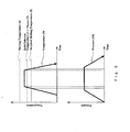
- Fig. 2 contains schematic diagrams showing an example of time charts for applying pressure and temperature during the recovery heat treatment process.
- the predetermined temperature of the recovery heat treatment process is set at the temperature higher than a solvus temperature 7 of the ⁇ ' phases or incipient melting temperature 8 and lower than a melting temperature 6, as shown in Fig. 2.
- a temperature 9 during the recovery heat treatment process S102 is raised to around the predetermined temperature.
- This predetermined temperature is a temperature that is suitable for the recovery heat treatment. It may be any temperature between the solution temperature of the precipitates, which are the ⁇ ' phases in this embodiment, and incipient melting temperature as adjusted due to the high pressure environment. However, even in this temperature range, higher temperature may cause deformation of the component by the weight of the component itself because the strength of the component is weakened in the high temperature. Therefore, the temperature of the recovery heat treatment may be determined in such a way that the component will not severely deform due to its weight.
- pressure 10 is increased and held at the predetermined pressure during the recovery heat treatment.
- This pressure may be set at any pressure that can avoid depression of the melting points of the grain boundary strengthening elements or other impurity elements segregating along the dendrite boundaries, and can accelerate diffusion of the ⁇ ' phases so that damages or defects such as casting defects, creep or fatigues, some of which is caused during the operation, can be recovered.
- the pressure is preferably less than the pressure at which the component will severely deform.
- the pressure 10 is kept at the predetermined pressure at the time when the temperature 9 is raised to exceed the solvus temperature 7 of the ⁇ ' phases or incipient melting temperature 8.
- the cooling rate of the component after the recovery heat treatment may be preferably set between 10 to 100°C/min.
- the solution heat treatment S 103 and the aging heat treatment S 104 are applied after the recovery heat treatment S102.
- the solution heat treatment S103 may be applied by holding the temperature at a predetermined temperature, which is suitable for the solution heat treatment S103, in connection with decreasing temperature at the end of the recovery heat treatment process S102 and then quenching the component. This can be applied when the apparatus for the recovery heat treatment is equipped with a gas cooler which can accomplish a cooling rate greater than 40°C/min.
- the incipient melting due to the segregation of the grain boundary strengthening elements can be avoided because the component is under high pressure environment, which raises the incipient melting temperature, when the temperature 9 is raised to exceed the solvus temperature 7 of the ⁇ ' phases and/or incipient melting temperature 8. Therefore, recovery heat treatment S102 may be done so that the ⁇ ' phases are fullly dissolved without having defects caused by the incipient melting.
- the embodiment is preferably suitable for the component of nickel base precipitation strengthening type alloy, whose main precipitation strengthening phases are the ⁇ ' phases [Ni 3 (Al, Ti)]. Particularly, it may be suitable for the component of a convensional casting (equiaxed grain) or a directionally solidified casting.
- These alloys have a characteristic that a heat treatment processed at the temperature between the solvus temperature of the ⁇ ' phases and the incipient melting temperature is difficult to apply, because maximum temperature of a heat treatment after casting is close to the solvus temperature of the ⁇ ' phases, which are main precipitation strengthening phases, or that the incipient melting temperature is less than the solvus temperature.
- the ⁇ ' phases of the nickel base alloy which is degraded or deteriorated after its use, are coarsened and rounded to a spherical or flat shape having sizes over 1 ⁇ m, and minute ⁇ ' phases having sizes under 0.1 ⁇ m disappear.
- the embodiment may recover the microstructure of the alloy comprising the ⁇ ' phases of cubic shape having the average size from 0.3 to 0.8 ⁇ m, and fine spherical ⁇ ' phases having the size under 0.1 ⁇ m.
- This microstructure of the alloy which is refurbished by the embodiment, may be equivalent to or even better than that of the newly manufactured component.
- the component is placed under high pressure and high temperature environment. Controlling the temperature during the recovery heat treatment S102 is made easier because inert gas, such as an argon gas, introduced and pressurized in the pressure vessel may have larger density and thermal expansion coefficient, which contributes to facilitate heat convection during the recovery heat treatment.
- inert gas such as an argon gas
- density of argon gas in the condition of 1000°C and 100MPa is as 1000 times as the density in the normal pressure. This also contributes to creating uniformity of the temperature distribution inside the pressure vessel.
- the refurbishing process in accordance with the embodiment may be preferably applied when the component, to which the refurbishing process is applied, has creeps or fatigues that may not cause recrystalization after the process. This may be accomplished by refurbishing the component within an administered life, which is predetermined based on design life of the component. Alternatively, the refurbishing process may be applied when an effective cross section of the component, which sustains an external force caused by an environmental factor, will have more than a half of the administered life after the process. In other words, the refurbishing process may be applied when a local creep deformation (creep strain) of the component is within 1% at critical portion and within 2% at non-critical portion before entering an acceleration range from a steady range.
- the component, to which the refurbish process is applied may be a gas turbine component which is exposed to the high temperature such as a turbine blade, a turbine nozzle, the combustion liner or the transition piece.
- the embodiments of the invention are not limited to these particular components, and may be applied to any component subject to deterioration analogous to the identified components.
- the IN738LC superalloy has the chemical composition including C, Cr, Co, W, Mo, Ti, Al, Nb, Ta, B, Zr, and Ni. Furthermore, the IN738LC superalloy has processed a heat treatment after casting at the temperature that the ⁇ ' phases, which are the main precipitation strengthening phases of the IN738LC superalloy, can partially dissolve into the ⁇ phases, which are base metal.
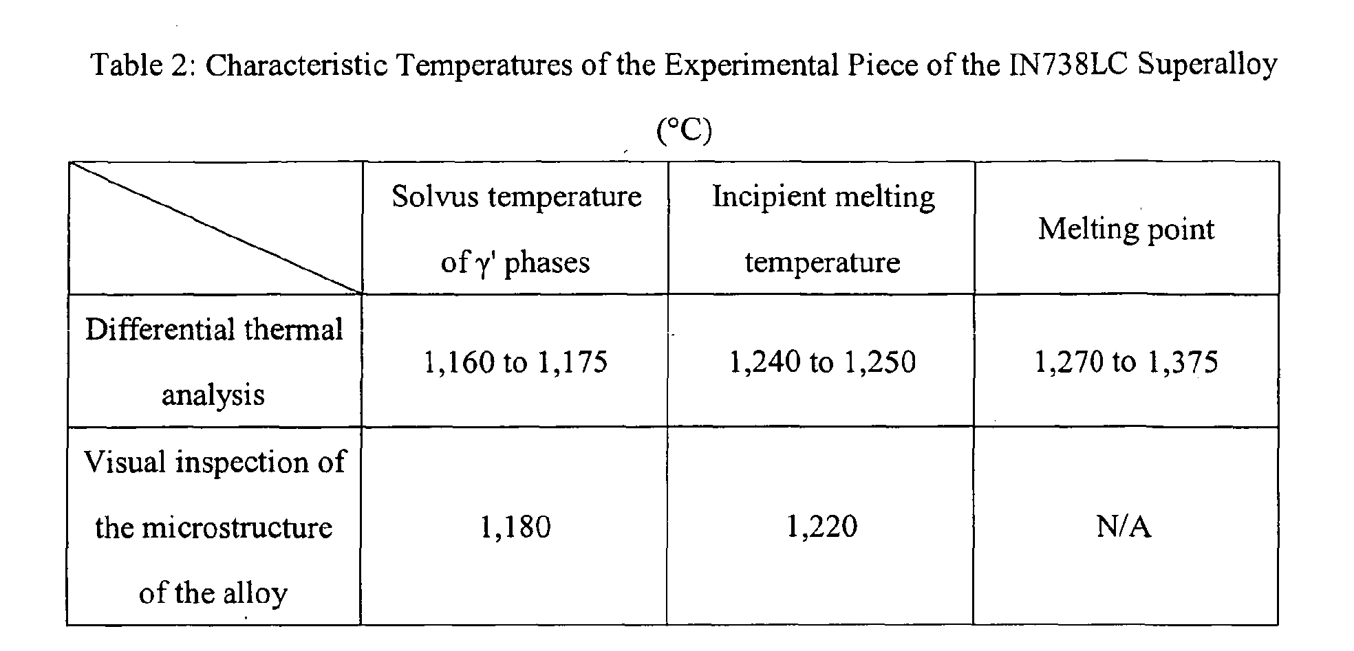
- the solvus temperature of the ⁇ ' phases, the incipient melting temperature, and melting point of the experimental piece of the IN738LC superalloy were obtained through differential thermal analysis.
- the solvus temperature of the ⁇ ' phases and the incipient melting temperature are obtained by visually inspecting the microstructure of test pieces that have been held at the temperature and then have been quenched.
- Table 2 below shows the temperatures provided (a) through the differential thermal analysis and (b) visual inspection of the heated and quenched test piece.
- the solvus temperature of the ⁇ ' phases was 1,160 to 1,175°C.
- the incipient melting temperature which is the temperature the incipient melting begins, was 1,240 to 1,250°C.
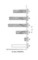
- Fig. 3 shows the result of the experimentation.
- the vertical axis of the graph indicates creep rupture life of the alloys including the alloy refurbished in accordance with the embodiment.
- the creep rupture life of the alloys are shown as ratios against a newly manufactured alloy 11.
- test pieces of different conditions including refurbished alloy 16 referred to as "prior-pressurized HIP-processed alloy 16" in accordance with the embodiment are shown.
- Numeral 11 indicates a newly manufactured alloy.
- Numeral 12 indicates a creep-degraded alloy, which has a creep damage caused in a condition of 900°C and 300N.
- Numeral 13 indicates a 1,205°C solution-aging alloy, which is the creep-degraded alloy 12 subjected the solution heat treatment S103 at 1,205°C and the aging heat treatment S104 at 843°C, which is a typical temperature for the aging heat treatment.
- the temperature (1,205°C) of this solution heat treatment was higher than the solvus temperature of the ⁇ ' phases.
- Numeral 14 indicates a solution-aging alloy, which is the creep-degraded alloy 12 subjected to the solution heat treatment S103 at 1,120°C, which is a typical temperature for the solution heat treatment, and the aging heat treatment S 104 at its typical temperature.
- Numeral 15 indicates a prior-heated HIP-processed alloy, which is the creep-degraded alloy 12 subjected to the recovery heat treatment, but without pressurizing prior to heating. More precisely, during the recovery heat treatment of the prior-heated HIP-processed alloy 15, the temperature was first increased to 1,205°C and then the pressure was increased over 100MPa.
- Numeral 16 indicate the prior-pressurized HIP-processed alloy, which is the creep-degraded alloy 12 processed in accordance with this embodiment, which means the temperature of the alloy is increased to the predetermined temperature under the predetermined pressure during the recovery heat treatment process S102. More precisely, during the recovery heat treatment process S102 of the prior-pressurized HIP-processed alloy 16, the pressure was first increased over 100MPa and then the temperature was increased from 1,120°C to 1,205°C.
- the strength of three test pieces cut from each of the alloys 11 to 16 were examined. Each result shown in Fig. 3 for each of alloys 11 to 16 is based upon strength data obtained by examining the three test pieces.
- the average creep rupture life of the newly manufactured alloy 11 is defined as 1.0.
- bar line of each of the graph indicates a range of a maximum value and a minimum value.
- a box shows a range between -3 ⁇ and +3 ⁇ , wherein ⁇ means the standard deviation.
- a horizontal bar shows a center value and a point shows a mean (an average) value.
- HIP-processed alloys 15 and 16 both of which were applied typical solution heat treatment and aging heat treatment after the recovery heat treatment, had a creep rupture life greater than the newly manufactured alloy 11.
- the result of prior-heated HIP-processed alloy 15 had a deviation larger than that of the newly manufactured alloy 11.
- the prior-pressurized HIP-processed alloy 16 had a considerably smaller deviation.
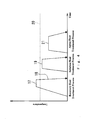
- Fig. 4 is a schematic time chart showing the temperature during a refurbishment process of the prior art (which is for example shown in Japanese Patent Publication (Kokai) No.8-271501).
- This refurbishment process comprises the recovery heat treatment process 17 (referred to as "HIP process"), a partial solution heat treatment process 19, and the aging heat treatment process 21.
- a numeral 20 indicate a solvus temperature of the ⁇ ' phases.
- the HIP process is applied at the temperature higher than the solvus temperature 20 of the ⁇ ' phases.
- the partial solution heat treatment process 19 is applied at the temperature less than the solvus temperature 20 of the ⁇ ' phases.
- the aging heat treatment process 21 is applied at the temperature less than the temperature of the solution heat treatment process 19.
- a cooling process 18 of the HIP process 17 is a furnace cooling.
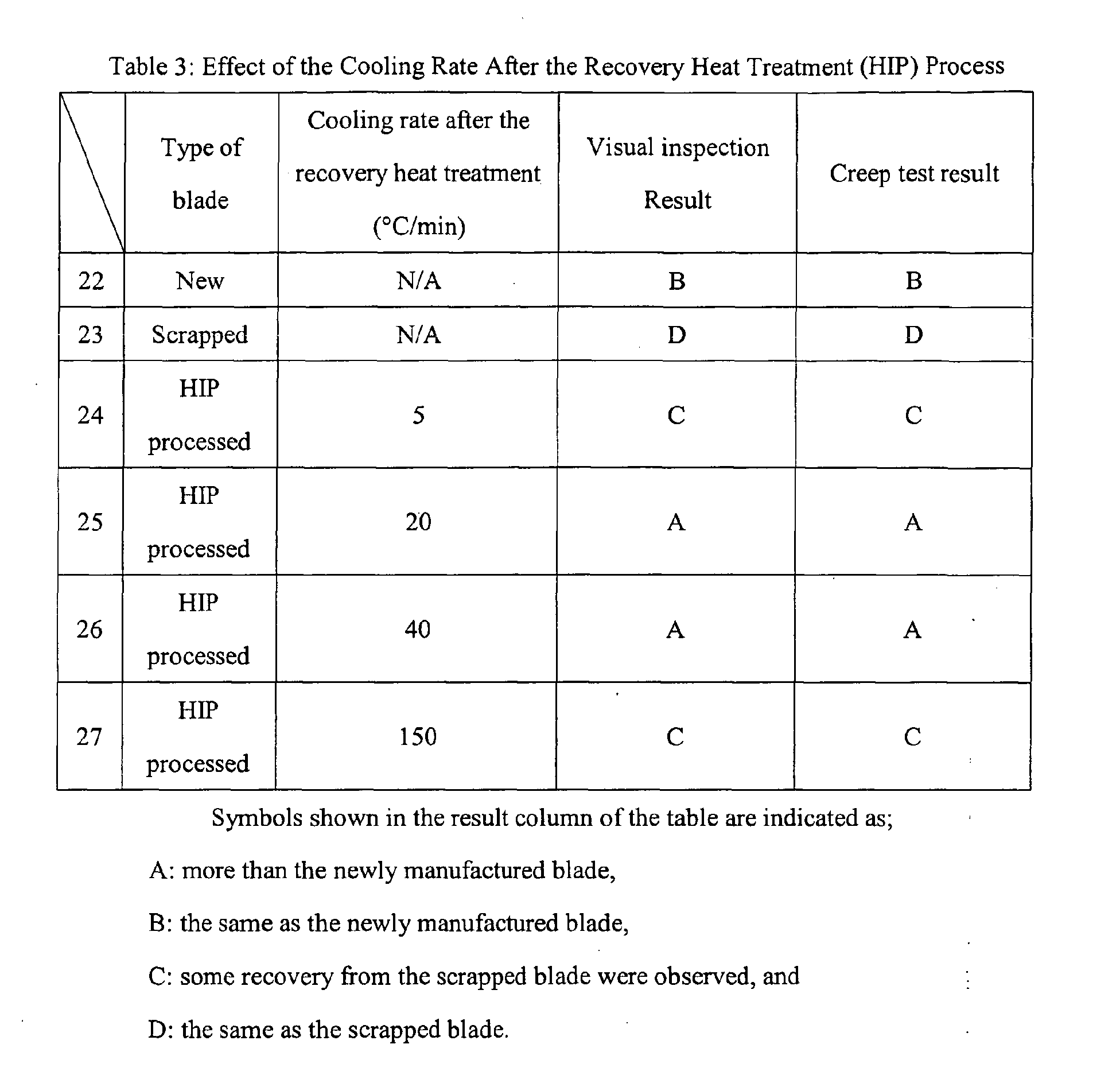
- Table 3 shows the results of experimentation of the strengths and visual inspections of the microstructure of the alloys. Test pieces of newly manufactured blade 22, scrapped blade 23, and refurbished blades 24 to 27 were examined. The scrapped blade 23 was used in actual gas turbine until their design life. The refurbished blades 24 to 27 had been used in actual gas turbine until their design life, and then refurbished.
- Each of the refurbishing process included the recovery heat treatment process (HIP process) 17, the solution heat treatment process 19, and the aging heat treatment process 21.
- the temperature of the solution heat treatment process 19 was a typical temperature for the solution heat treatment, which was less than the solvus temperature 20 of the ⁇ ' phases.
- the temperature of the aging heat treatment process 21 was also typical temperature for the aging heat treatment, which was less than the temperature of the solution heat treatment 19.
- the cooling rates during the cooling process 18 were set as 5, 20, 40, and 150°C/min for each of the refurbished blades 24 to 27, respectively.
- test piece 24 was gradually cooled by furnace cooling, wherein the cooling rate during the cooling process 18 was 5°C/min.
- the test piece!27 was rapidly cooled by argon gas, wherein the cooling rate was 150°C/min.
- test pieces 25 and 26 are cooled at the cooling rates, which were 20°C/min and 40°C/min respectively, between those of gradual cooling and rapid cooing.
- test pieces 25, 26 recovered to have the microstructures of the alloy and the creep strengths equivalent to or better than those of the newly manufactured blade 22.
- Fig. 5 is a graph shows the result of the creep rupture time in accordance with the experimentation shown in Table 3.
- Fig. 6 is a schematic drawing of microstructures of the test pieces used in the experimentation.
- the microstructure of the newly manufactured blade 22 comprises cuboidal ⁇ ' phases 28 having the sizes between 0.3 and 0.7 ⁇ m, and fine spherical ⁇ ' phases 29 having the size under 0.1 ⁇ m.
- the microstructure of the scrapped blade 23, which has been used in the gas turbine, comprises coarsened ⁇ ' phases 31, which have rounded shapes.
- the alloy degrades during the operation of the gas turbine as its microstructure has more coarsened ⁇ ' phases 31.
- the creep rupture time is considerably shortened due to this degradation and other damages.
- the microstructures of the refurbished blades 24 to 27 also include recovered cuboidal ⁇ ' phases 32, which are like the cuboidal ⁇ ' phases 28 in the microstructure of the newly manufactured blade 22.
- the coarsened ⁇ ' phases 31 are dissolved in a ⁇ phase 30, which is a base metal, during the recovery heat treatment process (HIP process) 17, and then the ⁇ ' phases re-precipitates during the cooling process 18, the solution heat treatment process 19, and the aging heat treatment process 21 like the newly manufactured blade 22.
- the sizes of the recovered cuboidal ⁇ ' phases 32 in the test piece 24, which was gradually cooled during the cooling process 18, are larger than the cuboidal ⁇ ' phases 28 in the newly manufactured blade 22 because recovered cuboidal ⁇ ' phases 32 enlarges during the cooling process 18.
- This enlargement of the recovered cuboidal ⁇ ' phases 32 during the cooling process 18 is not recovered by the following solution heat treatment process 19 and aging heat treatment 21. And, sufficient creep strength is not obtained with the test piece 24.
- the recovered cuboidal ⁇ ' phases 32 may not grow enough.
- the size of the recovered cuboidal ⁇ ' phases 32 which are shown in microstructure of the test piece 27 in Fig. 6, may not be recovered by the following solution heat treatment process 19 and aging heat treatment 21. In this case, the creep strength is not sufficiently recovered.
- desired cooling rate for recovering the microstructure of alloy sufficiently may be in a range between 20°C/min and 40°C/min. Therefore, the apparatus for the recovery heat treatment may be preferably equipped with a gas cooler which can accomplish a cooling rate greater than 40°C/min.
- Fig. 7 is a graph illustrating the relationship between the sizes of the ⁇ ' phases and the creep life.
- numeral 33 indicates a correlation curve between the sizes of the ⁇ ' phases and the creep rupture life.
- Numeral 34 indicates the creep rupture life of the newly manufactured blade.
- the refurbished blade may have sufficient creep strength.
- the coarsened ⁇ ' phases 31 having the size more than 0.7 ⁇ m, recovered to be within 0.3 to 0.7 ⁇ m, by the embodiment may have sufficient strength compared to the newly manufactured blade.
- timing of the refurbishing process of the component is explained below.
- Fig. 8 is a graph showing the creep curve of the IN738LC superalloy with schematic drawings of matrices of the refurbished alloys.
- the vertical axis indicates creep strain of the IN738LC superalloy that is applied stress of 240N at 900°C.
- Horizontal axis indicates time that the stress has been applied.
- numerals 35 to 37 are the schematic drawings of the grain boundaries of the ⁇ phases, which are matrices of the alloy, of the refurbished alloys. Each of the schematic drawings 35 to 37 is regarding the refurbished alloy that is refurbished at the time the arrow indicates.
- the microstructure 35 shows grain boundaries of the ⁇ phases, which are matrices, of the new alloy.
- the microstructure 36 shows grain boundaries of the ⁇ phases, which are matrices, of the alloy refurbished by the HIP process, solution heat treatment process, and aging heat treatment process when the creep strain of the alloy is 0.5%.
- the microstructure 37 shows grain boundaries of the ⁇ phases, which are matrices, of the alloy refurbished by the HIP process, solution heat treatment process, and aging heat treatment process when the creep strain of the alloy is 2%.
- the microstructure 37 which is refurbished when the creep strain is 2%, comprises smaller grains of the ⁇ phases, which are re-crystallized during the HIP process. These smaller grains of the ⁇ phases weaken the strength of the alloy. Therefore, the refurbishing process is preferably applied to the component before the local creep strain of the alloy exceeds 2%.
- Fig. 9 shows a result of the three-dimensional measurement of the turbine blade before and after the refurbish process that includes a recovery heat treatment process (HIP process) though not necessarily where pressure is increased first.
- the recovery heat treatment process was applied to the turbine blade that had been used for 60,000 hours in the gas turbine at 1,205°C and 100MPa.
- FIG. 9 two-dimensional shapes around the tip portion of the blades are shown. A bold line indicates the shape of the blade before the refurbishment process, while a fine line indicates after the refurbishment process.
- Fig. 10 shows a result of the three-dimensional measurement of the turbine blade before and after typical solution heat treatment process, which is applied without pressurizing.
- the solution heat treatment process was applied to the turbine blade that had been used for 60,000 hours in the gas turbine at 1,205°C and reduced pressure environment.
- Fig. 10 two-dimensional shapes around the tip portion of the blades are shown as same as Fig. 9.
- a bold line indicates the shape of the blade before the refurbish process, while a fine line indicates after the refurbish process.
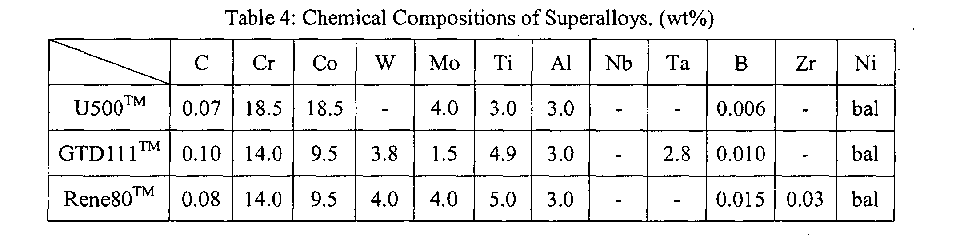
- the refurbishing process can be applied, not only the IN738LC superalloy, but also U500TM superalloy, GTD111TM superalloy, and Rene80TM superalloy. Chemical compositions of these superalloys are shown in Table 4.
- the refurbish process in accordance with the embodiment recovered the microstructures of turbine blades made of these superalloys or directionally solidifyed ones.
- components using nickel base alloys such as a combustion liner, a transition piece and a turbine nozzle can be recovered by the refurbish process.
Landscapes
- Chemical & Material Sciences (AREA)
- Engineering & Computer Science (AREA)
- Mechanical Engineering (AREA)
- Materials Engineering (AREA)
- Metallurgy (AREA)
- Physics & Mathematics (AREA)
- Organic Chemistry (AREA)
- Thermal Sciences (AREA)
- Crystallography & Structural Chemistry (AREA)
- Chemical Kinetics & Catalysis (AREA)
- Plasma & Fusion (AREA)
- General Engineering & Computer Science (AREA)
- Turbine Rotor Nozzle Sealing (AREA)
Abstract
Description
| Chemical Composition of the IN738LC Superalloy (wt%) | |||||||||||
| C | Cr | Co | W | Mo | Ti | Al | Nb | Ta | B | Zr | Ni |
| 0.1 | 16 | 8.5 | 2.6 | 1.75 | 3.4 | 3.4 | 0.9 | 1.75 | 0.01 | 0.05 | bal |
Claims (26)
- A method for refurbishing a service-degraded component formed of a precipitation strengthening type of alloy for a gas turbine, comprising:performing a recovery heat treatment on the component in an environment having a predetermined pressure that is greater than atmospheric pressure,wherein the temperature of the component is increased to a predetermined temperature in the environment having the predetermined pressure;performing a solution heat treatment, which is processed under reduced pressure or inert gas atmosphere, the solution heat treatment being performed after performing the recovery heat treatment; andperforming an aging heat treatment, which is processed under reduced pressure or an inert gas atmosphere, the aging heat treatment being performed after performing the recovery heat treatment.
- The method for refurbishing a service-degraded component according to claim 1, wherein the step of performing recovery heat treatment further comprises, after starting the recovery heat treatment, decreasing the temperature of the component from the predetermined temperature before starting decreasing the pressure from the predetermined pressure.
- The method for refurbishing a service-degraded component according to claim 1, wherein the step of performing recovery heat treatment comprises:wherein the predetermined temperature is more than at least one of a solvus temperature of γ' phases in the alloy or the incipient melting temperature of the component.increasing pressure of the component to the predetermined pressure, wherein the predetermined pressure can prevent the component from incipient melting;retaining the pressure at the predetermined pressure; andincreasing the temperature of the component to the predetermined temperature after the pressure has reached the predetermined pressure,
- The method for refurbishing a service-degraded component according to claim 3, wherein the recovery heat treatment further comprises:decreasing the temperature of the component from the predetermined temperature using a cooling rate, and;decreasing the pressure of the component from the predetermined pressure after the temperature is decreased to less than at least one of the solvus temperature of γ' phases in the alloy or the incipient melting temperature of the component.
- The method for refurbishing a service-degraded component according to claim 4, wherein the cooling rate is in a range between 10 and 100 degrees centigrade per minute.
- The method for refurbishing a service-degraded component according to claim 4, wherein the cooling rate is in a range between 20 and 40 degrees centigrade per minute.
- The method for refurbishing a service-degraded component according to claim 1,
wherein the alloy includes Ni base metal,
wherein a main precipitation strengthening phases are γ' phases. - The method for refurbishing a service-degraded component according to claim 7,
wherein the alloy has been subjected to a heat treatment at time of manufacture, whose maximum temperature is less than a solvus temperature after the alloy had been cast at time of manufacture, the solvus temperature being a temperature at which the γ' phases can be dissolved in γ phases as its base metal. - The method for refurbishing a service-degraded component according to claim 7, wherein the alloy has been subjected to a heat treatment at time of manufacture after the alloy had been cast at time of manufacture,
wherein the heat treatment enables γ' phases dissolved partially in γ phases as its base metal. - The method for refurbishing a service-degraded component according to claim 7, further comprising:wherein the step of performing the recovery heat treatment is performed to the components having an coarsened γ' phases including sizes larger than 0.7µm.inspecting the γ' phases in the alloy of the component,
- The method for refurbishing a service-degraded component according to claim 1, wherein;
the component includes at least one element selected from the group consisting of B, Zr, Hf and C. - The method for refurbishing a service-degraded component according to claim 1, wherein;
the recovery heat treatment is performed during an expected life of the component. - The method for refurbishing a service-degraded component according to claim 1, wherein the recovery heat treatment is performed when the component reaches its estimated life based on an examination-of the component.
- The method for refurbishing a service-degraded component according to claim 1, wherein the recovery heat treatment is performed before the local creep strain of the component reaches 2%.
- A gas turbine component refurbished by the method according to claim 1.
- A gas turbine, comprising the gas turbine component according to claim 15.
- The method for refurbishing a service-degraded component according to claim 3, wherein the predetermined temperature is greater than both the solvus temperature of γ' phases in the alloy and the incipient melting temperature.
- The method for refurbishing a service-degraded component according to claim 1, wherein the step of performing recovery heat treatment comprises:increasing pressure of the component in order to prevent the component from incipient melting; andthereafter increasing the temperature of the component to the predetermined temperature for performing the heat treatment recovery.
- The method for refurbishing a service-degraded component according to claim 1, wherein the resulting component has γ' phases having a size in a range between 0.3 and 0.7µm.
- A method for refurbishing or strengthening a component formed of a precipitation strengthening type of alloy, comprising:wherein the first predetermined pressure is equal to or greater than the second predetermined pressure.performing a recovery heat treatment on the component in an environment having a first predetermined pressure greater than atmospheric pressure and a predetermined temperature, wherein the pressure is increased above a second predetermined pressure before the temperature is increased to the predetermined temperature, and
- The method of refurbishing or strengthening a component according to claim 20, further comprising:performing a solution heat treatment, which is performed under reduced pressure or inert gas atmosphere, the solution heat treatment being performed after the recovery heat treatment; andperforming an aging heat treatment, which is performed under reduced pressure or an inert gas atmosphere, the aging heat treatment being performed after the solution heat treatment.
- The method of refurbishing or strengthening a component according to claim 21, wherein the second predetermined pressure is such that raising the pressure above the second predetermined pressure prevents incipient melting of the alloy of the component.
- A method for refurbishing or strengthening a component formed of a precipitation strengthening type of alloy, comprising:performing a recovery heat treatment to the component in an environment having a predetermined pressure greater than atmospheric pressure and a predetermined temperature,wherein an environmental condition of the environment is adjusted to prevent incipient melting of the alloy of the component before the temperature is increased to the predetermined temperature;performing a solution heat treatment, which is performed under reduced pressure or inert gas atmosphere, the solution heat treatment being performed after the recovery heat treatment; andperforming an aging heat treatment, which is performed under reduced pressure or an inert gas atmosphere, the aging heat treatment being performed after the recovery heat treatment.
- The method for refurbishing or strengthening a component of claim 23, wherein the step of adjusting of the environmental condition raises the incipient melting temperature of the component above the predetermined temperature.
- The method for refurbishing or strengthening a component of claim 24, wherein the environmental condition is pressure.
- A gas turbine having a component refurbished or strengthened by carrying out a method for refurbishing a gas turbine component comprising the steps of claim 23.
Applications Claiming Priority (2)
| Application Number | Priority Date | Filing Date | Title |
|---|---|---|---|
| JP2004174358A JP4468082B2 (en) | 2004-06-11 | 2004-06-11 | Material degradation / damage recovery processing method for gas turbine parts and gas turbine parts |
| JP2004174358 | 2004-06-11 |
Publications (3)
| Publication Number | Publication Date |
|---|---|
| EP1605074A1 true EP1605074A1 (en) | 2005-12-14 |
| EP1605074B1 EP1605074B1 (en) | 2011-02-16 |
| EP1605074B2 EP1605074B2 (en) | 2017-01-18 |
Family
ID=35044643
Family Applications (1)
| Application Number | Title | Priority Date | Filing Date |
|---|---|---|---|
| EP05011190.5A Expired - Lifetime EP1605074B2 (en) | 2004-06-11 | 2005-05-24 | Thermal recovery treatment for a service-degraded component of a gas turbine |
Country Status (4)
| Country | Link |
|---|---|
| US (1) | US7632363B2 (en) |
| EP (1) | EP1605074B2 (en) |
| JP (1) | JP4468082B2 (en) |
| DE (1) | DE602005026346D1 (en) |
Cited By (10)
| Publication number | Priority date | Publication date | Assignee | Title |
|---|---|---|---|---|
| EP1914328A3 (en) * | 2006-10-18 | 2008-04-30 | United Technologies Corporation | Method for preventing formation of cellular gamma prime in cast nickel superalloys |
| EP2236635A1 (en) * | 2009-03-31 | 2010-10-06 | Hitachi Ltd. | NI-base alloy and method of producing the same |
| EP2412833A3 (en) * | 2010-07-27 | 2012-04-11 | General Electric Company | Nickel alloy and articles |
| RU2459885C1 (en) * | 2011-07-15 | 2012-08-27 | Общество с ограниченной ответственностью "Производственное предприятие Турбинаспецсервис" | Method of reduction thermal treatment of articles from refractory nickel alloys |
| EP2876172A1 (en) * | 2013-11-26 | 2015-05-27 | MTU Aero Engines GmbH | Method for producing and repairing components of a turbo engine made from nickel-based superalloys |
| WO2015160605A1 (en) * | 2014-04-14 | 2015-10-22 | Siemens Energy, Inc. | Superalloy component braze repair with isostatic solution treatment |
| EP3326747A1 (en) * | 2016-11-28 | 2018-05-30 | Mitsubishi Hitachi Power Systems, Ltd. | Nickel-based alloy regenerated member, and method for manufacturing same |
| CN109957744A (en) * | 2017-12-26 | 2019-07-02 | 三菱日立电力系统株式会社 | The manufacturing method of nickel-base alloy remanufactured component and the remanufactured component |
| EP3808936A1 (en) * | 2019-10-18 | 2021-04-21 | Raytheon Technologies Corporation | Method of servicing a gas turbine engine or components |
| FR3117506A1 (en) * | 2020-12-16 | 2022-06-17 | Safran Aircraft Engines | METHOD FOR MANUFACTURING A MONOCRYSTALLINE SUPERALLOY PART |
Families Citing this family (15)
| Publication number | Priority date | Publication date | Assignee | Title |
|---|---|---|---|---|
| US7854064B2 (en) * | 2006-06-05 | 2010-12-21 | United Technologies Corporation | Enhanced weldability for high strength cast and wrought nickel superalloys |
| DE102006034055A1 (en) * | 2006-07-20 | 2008-01-24 | Mtu Aero Engines Gmbh | Method of repairing a vane segment for a jet engine |
| KR100757258B1 (en) * | 2006-10-31 | 2007-09-10 | 한국전력공사 | METHOD AND APPARATUS FOR MANUFACTURING NICKEL-BASED CHUCK ALLOY PARTS FOR GAS TURBINE BY HOT-TEMPERATURE PRESSURE-BASE PROCESSING |
| EP1967312A1 (en) * | 2007-03-06 | 2008-09-10 | Siemens Aktiengesellschaft | Method for repair soldering of a component under vacuum and a selected oxygen partial pressure |
| US7493809B1 (en) * | 2007-10-04 | 2009-02-24 | General Electric Company | Method and system for measuring deformation in turbine blades |
| JP5956205B2 (en) * | 2012-03-15 | 2016-07-27 | 日立金属Mmcスーパーアロイ株式会社 | Method for producing Ni-based alloy |
| CN102785062A (en) * | 2012-08-22 | 2012-11-21 | 南京德邦金属装备工程股份有限公司 | Titanium alloy plate expansion joint manufacturing method |
| CN103849744B (en) * | 2012-11-30 | 2015-09-09 | 宜兴北海封头有限公司 | A kind of end socket thermal treatment fixing tool |
| CN105717118B (en) * | 2016-03-14 | 2018-05-11 | 西北工业大学 | A kind of method of the remaining segregation of definite nickel-base high-temperature single crystal alloy |
| CN106929652B (en) * | 2017-02-15 | 2018-07-24 | 贵州大学 | Heat treatment method is precipitated to connecting bolt second-phase dispersion in a kind of GH4169 |
| US10625357B2 (en) * | 2017-05-26 | 2020-04-21 | Siemens Energy, Inc. | Braze repair of turbomachine engine component |
| US10718042B2 (en) * | 2017-06-28 | 2020-07-21 | United Technologies Corporation | Method for heat treating components |
| CN113151761A (en) * | 2021-01-27 | 2021-07-23 | 中国航发北京航空材料研究院 | Repair method for alloy creep damage |
| CN113699347B (en) * | 2021-09-10 | 2022-06-07 | 北京航空航天大学 | An anti-recrystallization method in the process of repairing turbine blades after service |
| CN117568728B (en) * | 2023-11-21 | 2026-01-02 | 常州钢研极光增材制造有限公司 | Aging and heat treatment methods for GH4099 alloy |
Citations (4)
| Publication number | Priority date | Publication date | Assignee | Title |
|---|---|---|---|---|
| GB2098119A (en) * | 1981-05-11 | 1982-11-17 | Chromalloy American Corp | Method of improving mechanical properties of alloy parts |
| US5077004A (en) * | 1986-05-07 | 1991-12-31 | Allied-Signal Inc. | Single crystal nickel-base superalloy for turbine components |
| JPH11335802A (en) * | 1998-05-26 | 1999-12-07 | Toshiba Corp | Material deterioration / damage recovery treatment method for gas turbine parts and gas turbine parts subjected to this treatment |
| JP2001240950A (en) * | 2000-03-02 | 2001-09-04 | Toshiba Corp | High-temperature component recycling processing method |
Family Cites Families (10)
| Publication number | Priority date | Publication date | Assignee | Title |
|---|---|---|---|---|
| GB1510824A (en) | 1974-06-19 | 1978-05-17 | Gen Electric | Method for metal castings |
| ZA762776B (en) | 1975-06-16 | 1977-04-27 | Cabot Corp | Method of salvaging and restoring useful properties to used and retired metal articles |
| JPS55113833A (en) | 1979-02-21 | 1980-09-02 | Kobe Steel Ltd | Treating method for cast material by hot hydrostatic press |
| US4302256A (en) † | 1979-11-16 | 1981-11-24 | Chromalloy American Corporation | Method of improving mechanical properties of alloy parts |
| JPS5762884A (en) | 1980-09-30 | 1982-04-16 | Kawasaki Heavy Ind Ltd | Treatment of welding |
| JPS57207163A (en) | 1981-06-17 | 1982-12-18 | Chromalloy American Corp | Improvement of alloy part mechanical properties |
| US4975124A (en) † | 1989-02-06 | 1990-12-04 | United Technologies Corporation | Process for densifying castings |
| JP2940064B2 (en) | 1990-04-24 | 1999-08-25 | 神鋼電機株式会社 | Inverter power supply for induction heating |
| JP2000080455A (en) | 1998-09-03 | 2000-03-21 | Hitachi Ltd | Gas turbine blade and its regeneration heat treatment method |
| US20030041930A1 (en) † | 2001-08-30 | 2003-03-06 | Deluca Daniel P. | Modified advanced high strength single crystal superalloy composition |
-
2004
- 2004-06-11 JP JP2004174358A patent/JP4468082B2/en not_active Expired - Lifetime
-
2005
- 2005-05-24 DE DE602005026346T patent/DE602005026346D1/en not_active Expired - Lifetime
- 2005-05-24 EP EP05011190.5A patent/EP1605074B2/en not_active Expired - Lifetime
- 2005-06-10 US US11/149,231 patent/US7632363B2/en not_active Expired - Lifetime
Patent Citations (4)
| Publication number | Priority date | Publication date | Assignee | Title |
|---|---|---|---|---|
| GB2098119A (en) * | 1981-05-11 | 1982-11-17 | Chromalloy American Corp | Method of improving mechanical properties of alloy parts |
| US5077004A (en) * | 1986-05-07 | 1991-12-31 | Allied-Signal Inc. | Single crystal nickel-base superalloy for turbine components |
| JPH11335802A (en) * | 1998-05-26 | 1999-12-07 | Toshiba Corp | Material deterioration / damage recovery treatment method for gas turbine parts and gas turbine parts subjected to this treatment |
| JP2001240950A (en) * | 2000-03-02 | 2001-09-04 | Toshiba Corp | High-temperature component recycling processing method |
Non-Patent Citations (2)
| Title |
|---|
| PATENT ABSTRACTS OF JAPAN vol. 2000, no. 03 30 March 2000 (2000-03-30) * |
| PATENT ABSTRACTS OF JAPAN vol. 2000, no. 26 1 July 2002 (2002-07-01) * |
Cited By (21)
| Publication number | Priority date | Publication date | Assignee | Title |
|---|---|---|---|---|
| EP1914328A3 (en) * | 2006-10-18 | 2008-04-30 | United Technologies Corporation | Method for preventing formation of cellular gamma prime in cast nickel superalloys |
| US8906174B2 (en) | 2009-03-31 | 2014-12-09 | Mitsubishi Hitachi Power Systems, Ltd. | Ni-base alloy and method of producing the same |
| EP2236635A1 (en) * | 2009-03-31 | 2010-10-06 | Hitachi Ltd. | NI-base alloy and method of producing the same |
| US9562276B2 (en) | 2010-07-27 | 2017-02-07 | General Electric Company | Nickel alloy and articles |
| US8608877B2 (en) | 2010-07-27 | 2013-12-17 | General Electric Company | Nickel alloy and articles |
| EP2412833A3 (en) * | 2010-07-27 | 2012-04-11 | General Electric Company | Nickel alloy and articles |
| RU2459885C1 (en) * | 2011-07-15 | 2012-08-27 | Общество с ограниченной ответственностью "Производственное предприятие Турбинаспецсервис" | Method of reduction thermal treatment of articles from refractory nickel alloys |
| EP2876172A1 (en) * | 2013-11-26 | 2015-05-27 | MTU Aero Engines GmbH | Method for producing and repairing components of a turbo engine made from nickel-based superalloys |
| WO2015160605A1 (en) * | 2014-04-14 | 2015-10-22 | Siemens Energy, Inc. | Superalloy component braze repair with isostatic solution treatment |
| CN106163717A (en) * | 2014-04-14 | 2016-11-23 | 西门子能源有限公司 | Utilize the superalloy parts soldering reparation of isostatic pressed solution treatment |
| KR20160143826A (en) * | 2014-04-14 | 2016-12-14 | 지멘스 에너지, 인코포레이티드 | Superalloy component braze repair with isostatic solution treatment |
| US11072044B2 (en) | 2014-04-14 | 2021-07-27 | Siemens Energy, Inc. | Superalloy component braze repair with isostatic solution treatment |
| RU2686745C1 (en) * | 2016-11-28 | 2019-04-30 | Мицубиси Хитачи Пауэр Системс, Лтд. | Recovered nickel-based alloy construction element and method of manufacturing thereof |
| RU2686745C9 (en) * | 2016-11-28 | 2019-10-15 | Мицубиси Хитачи Пауэр Системс, Лтд. | Nickel-based alloy regenerated member, and method for manufacturing same |
| US10619233B2 (en) | 2016-11-28 | 2020-04-14 | Mitsubishi Hitachi Power Systems, Ltd. | Nickel-based alloy regenerated member, and method for manufacturing same |
| EP3326747A1 (en) * | 2016-11-28 | 2018-05-30 | Mitsubishi Hitachi Power Systems, Ltd. | Nickel-based alloy regenerated member, and method for manufacturing same |
| CN109957744A (en) * | 2017-12-26 | 2019-07-02 | 三菱日立电力系统株式会社 | The manufacturing method of nickel-base alloy remanufactured component and the remanufactured component |
| EP3505647A1 (en) * | 2017-12-26 | 2019-07-03 | Mitsubishi Hitachi Power Systems, Ltd. | Nickel-based alloy regenerated member and method for manufacturing same |
| EP3808936A1 (en) * | 2019-10-18 | 2021-04-21 | Raytheon Technologies Corporation | Method of servicing a gas turbine engine or components |
| US11725516B2 (en) | 2019-10-18 | 2023-08-15 | Raytheon Technologies Corporation | Method of servicing a gas turbine engine or components |
| FR3117506A1 (en) * | 2020-12-16 | 2022-06-17 | Safran Aircraft Engines | METHOD FOR MANUFACTURING A MONOCRYSTALLINE SUPERALLOY PART |
Also Published As
| Publication number | Publication date |
|---|---|
| US7632363B2 (en) | 2009-12-15 |
| EP1605074B1 (en) | 2011-02-16 |
| DE602005026346D1 (en) | 2011-03-31 |
| JP4468082B2 (en) | 2010-05-26 |
| EP1605074B2 (en) | 2017-01-18 |
| JP2005350744A (en) | 2005-12-22 |
| US20060016527A1 (en) | 2006-01-26 |
Similar Documents
| Publication | Publication Date | Title |
|---|---|---|
| US7632363B2 (en) | Method for refurbishing a service-degraded component of a gas turbine | |
| US6503349B2 (en) | Repair of single crystal nickel based superalloy article | |
| JP3032295B2 (en) | Heat treatment and repair of cobalt based superalloy articles | |
| US6629368B2 (en) | Method for isothermal brazing of single crystal components | |
| US4098450A (en) | Superalloy article cleaning and repair method | |
| EP2187020B1 (en) | Method for repairing turbine rotor blade | |
| US8813361B2 (en) | Gas turbine blade and manufacturing method thereof | |
| JP4554882B2 (en) | Method for restoring mechanical properties of a practical aircraft component cast Inconel 718 | |
| EP1540026B1 (en) | Property recovering method for nickel superalloy | |
| US8252376B2 (en) | Method for restoring the microstructure of a textured article and for refurbishing a gas turbine blade or vane | |
| US7959748B2 (en) | Method of manufacturing Ni-based superalloy component for gas turbine using one-step process of hot isostatic pressing and heat treatment and component manufactured thereby | |
| JP3559709B2 (en) | Material deterioration recovery method for gas turbine parts and gas turbine parts subjected to this treatment | |
| JP2001055928A (en) | Repair and reprocessing method for gas turbine hot parts | |
| JP2001240950A (en) | High-temperature component recycling processing method | |
| JP2003034853A (en) | HEAT TREATMENT METHOD FOR Ni-BASED ALLOY | |
| JP3887513B2 (en) | Recovery heat treatment method and regenerative combustor liner for gas turbine combustor liner | |
| EP0474484B1 (en) | Vane lug repair technique | |
| JP2020037899A (en) | Method for repairing gas turbine vane and method for manufacturing high strength gas turbine vane | |
| JP2002256887A (en) | Method for suppressing surface deterioration of gas turbine component and gas turbine component using the method | |
| JP2006183529A (en) | Method for reusing turbine blades and reused turbine blades | |
| HK1231013B (en) | Method of repairing and manufacturing of turbine engine components and turbine engine components |
Legal Events
| Date | Code | Title | Description |
|---|---|---|---|
| PUAI | Public reference made under article 153(3) epc to a published international application that has entered the european phase |
Free format text: ORIGINAL CODE: 0009012 |
|
| 17P | Request for examination filed |
Effective date: 20050524 |
|
| AK | Designated contracting states |
Kind code of ref document: A1 Designated state(s): AT BE BG CH CY CZ DE DK EE ES FI FR GB GR HU IE IS IT LI LT LU MC NL PL PT RO SE SI SK TR |
|
| AX | Request for extension of the european patent |
Extension state: AL BA HR LV MK YU |
|
| AKX | Designation fees paid |
Designated state(s): CH DE GB LI NL |
|
| 17Q | First examination report despatched |
Effective date: 20060406 |
|
| GRAP | Despatch of communication of intention to grant a patent |
Free format text: ORIGINAL CODE: EPIDOSNIGR1 |
|
| GRAS | Grant fee paid |
Free format text: ORIGINAL CODE: EPIDOSNIGR3 |
|
| GRAA | (expected) grant |
Free format text: ORIGINAL CODE: 0009210 |
|
| AK | Designated contracting states |
Kind code of ref document: B1 Designated state(s): CH DE GB LI NL |
|
| REG | Reference to a national code |
Ref country code: GB Ref legal event code: FG4D |
|
| REG | Reference to a national code |
Ref country code: CH Ref legal event code: NV Representative=s name: E. BLUM & CO. AG PATENT- UND MARKENANWAELTE VSP Ref country code: CH Ref legal event code: EP |
|
| REF | Corresponds to: |
Ref document number: 602005026346 Country of ref document: DE Date of ref document: 20110331 Kind code of ref document: P |
|
| REG | Reference to a national code |
Ref country code: DE Ref legal event code: R096 Ref document number: 602005026346 Country of ref document: DE Effective date: 20110331 |
|
| REG | Reference to a national code |
Ref country code: NL Ref legal event code: T3 |
|
| PLBI | Opposition filed |
Free format text: ORIGINAL CODE: 0009260 |
|
| 26 | Opposition filed |
Opponent name: SIEMENS AKTIENGESELLSCHAFT Effective date: 20110818 |
|
| REG | Reference to a national code |
Ref country code: DE Ref legal event code: R026 Ref document number: 602005026346 Country of ref document: DE Effective date: 20110818 |
|
| PLAX | Notice of opposition and request to file observation + time limit sent |
Free format text: ORIGINAL CODE: EPIDOSNOBS2 |
|
| PLBB | Reply of patent proprietor to notice(s) of opposition received |
Free format text: ORIGINAL CODE: EPIDOSNOBS3 |
|
| PLCK | Communication despatched that opposition was rejected |
Free format text: ORIGINAL CODE: EPIDOSNREJ1 |
|
| APBM | Appeal reference recorded |
Free format text: ORIGINAL CODE: EPIDOSNREFNO |
|
| APBP | Date of receipt of notice of appeal recorded |
Free format text: ORIGINAL CODE: EPIDOSNNOA2O |
|
| APAH | Appeal reference modified |
Free format text: ORIGINAL CODE: EPIDOSCREFNO |
|
| PLAB | Opposition data, opponent's data or that of the opponent's representative modified |
Free format text: ORIGINAL CODE: 0009299OPPO |
|
| APBQ | Date of receipt of statement of grounds of appeal recorded |
Free format text: ORIGINAL CODE: EPIDOSNNOA3O |
|
| R26 | Opposition filed (corrected) |
Opponent name: SIEMENS AKTIENGESELLSCHAFT Effective date: 20110818 |
|
| APBU | Appeal procedure closed |
Free format text: ORIGINAL CODE: EPIDOSNNOA9O |
|
| PUAH | Patent maintained in amended form |
Free format text: ORIGINAL CODE: 0009272 |
|
| STAA | Information on the status of an ep patent application or granted ep patent |
Free format text: STATUS: PATENT MAINTAINED AS AMENDED |
|
| 27A | Patent maintained in amended form |
Effective date: 20170118 |
|
| AK | Designated contracting states |
Kind code of ref document: B2 Designated state(s): CH DE GB LI NL |
|
| REG | Reference to a national code |
Ref country code: DE Ref legal event code: R102 Ref document number: 602005026346 Country of ref document: DE |
|
| REG | Reference to a national code |
Ref country code: CH Ref legal event code: AELC |
|
| REG | Reference to a national code |
Ref country code: NL Ref legal event code: FP |
|
| PGFP | Annual fee paid to national office [announced via postgrant information from national office to epo] |
Ref country code: NL Payment date: 20240415 Year of fee payment: 20 |
|
| PGFP | Annual fee paid to national office [announced via postgrant information from national office to epo] |
Ref country code: GB Payment date: 20240402 Year of fee payment: 20 |
|
| PGFP | Annual fee paid to national office [announced via postgrant information from national office to epo] |
Ref country code: DE Payment date: 20240326 Year of fee payment: 20 |
|
| PGFP | Annual fee paid to national office [announced via postgrant information from national office to epo] |
Ref country code: CH Payment date: 20240602 Year of fee payment: 20 |
|
| REG | Reference to a national code |
Ref country code: DE Ref legal event code: R071 Ref document number: 602005026346 Country of ref document: DE |
|
| REG | Reference to a national code |
Ref country code: NL Ref legal event code: MK Effective date: 20250523 |
|
| REG | Reference to a national code |
Ref country code: CH Ref legal event code: PL |
|
| REG | Reference to a national code |
Ref country code: GB Ref legal event code: PE20 Expiry date: 20250523 |
|
| PG25 | Lapsed in a contracting state [announced via postgrant information from national office to epo] |
Ref country code: GB Free format text: LAPSE BECAUSE OF EXPIRATION OF PROTECTION Effective date: 20250523 |