EP1604934A1 - Temporary safety spaces for elevators - Google Patents
Temporary safety spaces for elevators Download PDFInfo
- Publication number
- EP1604934A1 EP1604934A1 EP05103709A EP05103709A EP1604934A1 EP 1604934 A1 EP1604934 A1 EP 1604934A1 EP 05103709 A EP05103709 A EP 05103709A EP 05103709 A EP05103709 A EP 05103709A EP 1604934 A1 EP1604934 A1 EP 1604934A1
- Authority
- EP
- European Patent Office
- Prior art keywords
- car
- control station
- shaft
- elevator
- elevator according
- Prior art date
- Legal status (The legal status is an assumption and is not a legal conclusion. Google has not performed a legal analysis and makes no representation as to the accuracy of the status listed.)
- Granted
Links
Images

Classifications
-
- B—PERFORMING OPERATIONS; TRANSPORTING
- B66—HOISTING; LIFTING; HAULING
- B66B—ELEVATORS; ESCALATORS OR MOVING WALKWAYS
- B66B17/00—Hoistway equipment
- B66B17/34—Safe lift clips; Keps
-
- B—PERFORMING OPERATIONS; TRANSPORTING
- B66—HOISTING; LIFTING; HAULING
- B66B—ELEVATORS; ESCALATORS OR MOVING WALKWAYS
- B66B5/00—Applications of checking, fault-correcting, or safety devices in elevators
- B66B5/0043—Devices enhancing safety during maintenance
- B66B5/005—Safety of maintenance personnel
-
- Y—GENERAL TAGGING OF NEW TECHNOLOGICAL DEVELOPMENTS; GENERAL TAGGING OF CROSS-SECTIONAL TECHNOLOGIES SPANNING OVER SEVERAL SECTIONS OF THE IPC; TECHNICAL SUBJECTS COVERED BY FORMER USPC CROSS-REFERENCE ART COLLECTIONS [XRACs] AND DIGESTS
- Y10—TECHNICAL SUBJECTS COVERED BY FORMER USPC
- Y10T—TECHNICAL SUBJECTS COVERED BY FORMER US CLASSIFICATION
- Y10T74/00—Machine element or mechanism
- Y10T74/18—Mechanical movements
- Y10T74/18056—Rotary to or from reciprocating or oscillating
- Y10T74/18288—Cam and lever
Definitions
- the present invention relates to the creation of a temporary safety space within a shaft of an elevator and in particular to a device that mechanically limits the travel of an elevator car to create the required safety space for maintenance personnel working within the elevator shaft.
- the objective of the present invention is to simplify the procedure for performing maintenance operations within the shaft of an elevator installation.
- the invention seeks to overcome the need of the maintenance technician to remember to manually activate the bolts before commencing inspection speed travel using an inspection control station mounted on the car.
- the present invention provides an elevator having a car movable along guide rails mounted in a shaft.
- the elevator comprises an inspection control station mounted on the car and blocking means for selectively preventing movement of the car into a safety space within the shaft.
- Access means is provided to selectively enable operable access to the inspection control panel and configured to concurrently actuate the blocking means.
- the invention provides a method for creating a safety space in a shaft of an elevator having a car movable along guide rails mounted in the shaft.
- the method comprises the steps of mounting an inspection control station on the car and selectively preventing movement of the car into the safety space within the shaft using blocking means. Access to the inspection control station is selectively prevented such that accessing the inspection control station causes concurrent actuation of the blocking means.
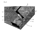
- An elevator 1 according to the present invention is shown in Fig. 1 and comprises an elevator car 4 movable vertically along guide rails 3 mounted within a shaft 2.
- the car 4 includes guide shoes 6 to ensure that the car 4 accurately follows the path of the guide rails.
- the control station 7 includes a pivotal cover 8 mounted on hinges 9.
- a lever 10 and support bracket 11 are mounted on the roof 5 alongside the control station cover 8.
- the lever 10 is interconnected, and moves concurrently, with the cover 8.
- the lever 10 is connected to an end of a central wire 13 of a first Bowden cable 12 while the sheath 14 of the Bowden cable 12 is fixed to the support bracket 11.
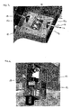
- the central wire 13 is fixed to a first pivotal cam 15 (shown in Fig. 3) and the sheath 14 is secured to a support bracket 15a.
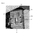
- the pivotal cam 15 is biased by a spring 16 towards an extended position shown in Fig. 4 where the cam 15 extends from the side of the car 4 to engage with a buffer 18 fixed by a bracket 19 to the guide rail 3 and thereby prevents further upward motion of the car 4 into the overhead safety space 24.
- the first pivotal cam 15 assumes its retracted position the car 4 can travel unhampered along its normal travel path.
- a second Bowden cable 17 is arranged in the same manner between the first pivotal cam 15 and a second pivotal cam 20 provided on the opposing side of the car 4.
- the second pivotal cam 20 is also biased by a spring 21 to an extended position where it extends from the side of the car 4 to engage with a buffer 18 fixed by a bracket 19 to the guide rail 3 and thereby prevents further upward motion of the car 4 into the overhead safety space 24.
- the car 4 In the retracted position of the second pivotal cam 20 the car 4 can travel unhampered along its normal travel path.
- Two safety contacts 22 and 23 are provided alongside the second pivotal cam 20 to indicate that the cam 20 is in the extended and retracted positions respectively. Since the first and second cams 15 and 20 are operated in direct sequence, an indication of the position of the second pivotal cam 20 is sufficient to establish the position of the first pivotal cam 15.
- the technician manually opens a landing door using a conventional triangular key.
- the safety chain of the elevator control is thereby broken and the elevator 1 is placed in a STOP condition.
- the technician then accesses the car roof 5, presses an emergency stop button (thereby maintaining the STOP condition even if the landing door closes) and opens the cover 8 of the inspection control station 7.
- the lever 10 moves concurrently with the cover 8 and through this action the central wires 13 of both Bowden cables 12 and 17 relax. Accordingly, the first and second cams 15 and 20 pivot into their extended positions under the spring bias.
- the safety contact 22 generates a signal to the elevator controller when the second cam 20 is in the fully extended position, and the elevator 1 is released from the STOP condition to inspection mode whereby the technician can move the car 4 at inspection speed within the shaft 2 using the inspection control station 7.
- inspection mode the car 4 is prevented from entering the overhead safety space 24 since the pivotal cams 15 and 20 are in the extended positions and engage with the rail mounted buffers 18 if the technician attempts to move the car 4 upwards into the safety space 24.
- the technician closes the control station cover 8 and the central wires 13 of both Bowden cables 12 and 17 are moved against the biasing force of the springs 16 and 21 and the cams 15 and 20 are thereby pivoted to their retracted positions.
- the safety contact 23 generates a signal for the elevator controller returning the elevator 1 from inspection mode into a STOP condition. Thereafter the technician leaves the shaft 2 through a landing door and activates a reset button which enables the elevator 1 to resume its normal operating mode.
- both of the pivotal cams 15 and 20 in the described embodiment are spring biased, it is clear the same effect can be reproduced using a single biasing spring 21 on the second pivotal cam 20 only since any movement of the second cam 20 automatically carries over to first cam 15 through the interconnecting second Bowden cable 17.
- control station cover 8 has been used to control access to the inspection control station 7.
- the inspection control station 7 may not have a cover 8, in which case the inspection controls are made inoperable until the lever 10 has been moved to create the safety space.
- the inspection control station 7 may be configured so that it can only be activated by a key operated switch. In this case, the movement of the key operated switch can also be used to actuate the pivotal cams 15 and 20 into their extended positions and thereby create the required safety space.
- the key operated switch may be mechanically coupled to the pivotal cams 15 and 20 or alternatively, movement of the key operated switch could complete an electrical circuit to actuate the pivotal cams 15 and 20.
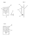
- FIGs. 6 and 7 illustrate a further embodiment of the invention, wherein an operating panel 30 mounted in the interior of the car 4 has dual purposes.
- This embodiment is thought to be particularly useful with the elevator described in EP 1052212. In normal operation, it functions as a normal car operating panel whereby users register their desired destination using the pushbuttons 32 on the panel 30. In maintenance situations, the technician can insert a key 36 into a key operated switch 34 on the side of the panel 30 transforming the panel 30 into a functioning inspection control station and simultaneously actuating the pivotal cams 15 and 20.
- Fig. 8 shows an alternative embodiment wherein the normal car operating panel 40 is transformed into a functioning inspection control station electronically by inputting a correct security code using the keypad 42 and thereby simultaneously actuating the pivotal cams 15 and 20.
Landscapes
- Maintenance And Inspection Apparatuses For Elevators (AREA)
- Cage And Drive Apparatuses For Elevators (AREA)
- Movable Scaffolding (AREA)
- Elevator Door Apparatuses (AREA)
- Types And Forms Of Lifts (AREA)
- Electrical Discharge Machining, Electrochemical Machining, And Combined Machining (AREA)
- Load-Engaging Elements For Cranes (AREA)
- Jib Cranes (AREA)
Abstract
Description
Claims (11)
- An elevator (1) having a car (4) movable along guide rails (3) mounted in a shaft (2) comprising:CHARACTERISED IN THATan inspection control station (7,30,40) mounted on the car (4); andblocking means (15,20,18) for selectively preventing movement of the car into a safety space (24) within the shaft (2);
access means (8,34,36,42) is provided to selectively enable operable access to the inspection control station (7) and configured to concurrently actuate the blocking means (15,20,18). - An elevator according to claim 1, wherein blocking means comprises a cam (15,20) mounted on the car (4) and configured to move between an extended position and a retracted position.
- An elevator according to claim 2, wherein the cam (15,20) in the extended position engages with a buffer (18) mounted on a guide rail (2) to prevent movement of the car (4) into the safety space (24).
- An elevator according to claim 2 or claim 3, wherein the cam (15,20) is spring biased towards the extended position.
- An elevator according to any of claims 2 to 4 further comprising a safety contact (22,23) to monitor the position of the cam (20).
- An elevator according to any preceding claim wherein the access means is a movable control station cover (8).
- An elevator according to claim 6 further comprising a lever (10) movable concurrently with the control station cover (8) and a Bowden cable (12) interconnecting the lever (10) and the blocking means (15,20;18).
- An elevator according to any of claims 1 to 5, wherein the inspection control station additionally functions as a car operating panel (30,40) and the access means (34,36) is configured to switch the inspection control station between its two functions.
- An elevator according to claim 8, wherein the access means comprises a key (36) and a key operated switch (34).
- An elevator according to claim 8, wherein the access means comprises a security code entry on a keypad (42).
- A method for creating a safety space (24) in a shaft (2) of an elevator (1) having a car (4) movable along guide rails (3) mounted in the shaft (2), comprising the steps of:CHARACTERISED BYmounting an inspection control station (7) on the car (4);selectively preventing movement of the car into the safety space (24) within the shaft (2) using blocking means (15,20;18)
selectively enabling operable access to the inspection control station (7) and concurrently actuating the blocking means (15,20;18).
Priority Applications (2)
| Application Number | Priority Date | Filing Date | Title |
|---|---|---|---|
| EP05103709A EP1604934B1 (en) | 2004-05-10 | 2005-05-03 | Temporary safety spaces for elevators |
| PL05103709T PL1604934T3 (en) | 2004-05-10 | 2005-05-03 | Temporary safety spaces for elevators |
Applications Claiming Priority (3)
| Application Number | Priority Date | Filing Date | Title |
|---|---|---|---|
| EP04405294 | 2004-05-10 | ||
| EP04405294 | 2004-05-10 | ||
| EP05103709A EP1604934B1 (en) | 2004-05-10 | 2005-05-03 | Temporary safety spaces for elevators |
Publications (2)
| Publication Number | Publication Date |
|---|---|
| EP1604934A1 true EP1604934A1 (en) | 2005-12-14 |
| EP1604934B1 EP1604934B1 (en) | 2009-06-17 |
Family
ID=34932102
Family Applications (1)
| Application Number | Title | Priority Date | Filing Date |
|---|---|---|---|
| EP05103709A Expired - Lifetime EP1604934B1 (en) | 2004-05-10 | 2005-05-03 | Temporary safety spaces for elevators |
Country Status (15)
| Country | Link |
|---|---|
| US (1) | US7258202B1 (en) |
| EP (1) | EP1604934B1 (en) |
| JP (1) | JP5043309B2 (en) |
| CN (1) | CN100445192C (en) |
| AT (1) | ATE433941T1 (en) |
| AU (1) | AU2005201954B2 (en) |
| BR (1) | BRPI0501732B1 (en) |
| CA (1) | CA2506643C (en) |
| DE (1) | DE602005014909D1 (en) |
| DK (1) | DK1604934T3 (en) |
| ES (1) | ES2328707T3 (en) |
| NO (1) | NO20052235L (en) |
| NZ (1) | NZ539927A (en) |
| PL (1) | PL1604934T3 (en) |
| RU (1) | RU2384512C2 (en) |
Cited By (6)
| Publication number | Priority date | Publication date | Assignee | Title |
|---|---|---|---|---|
| WO2009080867A1 (en) | 2007-12-21 | 2009-07-02 | Kone Corporation | Elevator and stop block arrangement for an elevator |
| AU2007203453B2 (en) * | 2006-07-26 | 2013-03-14 | Inventio Ag | Method of Controlling Access to an Elevator Car |
| US8708106B2 (en) | 2008-06-30 | 2014-04-29 | Kone Corporation | Elevator arrangement and method in elevator maintenance |
| EP2857340A1 (en) | 2013-10-07 | 2015-04-08 | Inventio AG | Method and arrangement for controlling the movement of an elevator cabin and elevator with such a device |
| US11858777B2 (en) | 2022-06-03 | 2024-01-02 | Otis Elevator Company | Elevator car with moving electrical box |
| WO2025051350A1 (en) * | 2023-09-05 | 2025-03-13 | Kone Corporation | Activation and/or deactivation of a temporary refuge space |
Families Citing this family (11)
| Publication number | Priority date | Publication date | Assignee | Title |
|---|---|---|---|---|
| DE102007049737A1 (en) * | 2007-10-16 | 2009-04-23 | Exclusive Lift Gmbh | Elevator installation for persons and / or loads with at least one elevator car |
| EP2727871B1 (en) * | 2012-10-30 | 2016-03-23 | KONE Corporation | An elevator and a method |
| FI125118B (en) * | 2013-01-07 | 2015-06-15 | Kone Corp | Elevator |
| EP2848570B1 (en) * | 2013-09-17 | 2016-08-10 | KONE Corporation | An elevator |
| US9359171B1 (en) * | 2015-01-20 | 2016-06-07 | Inventio Ag | Safety system for a lift installation and safety helmet as individual component of such a safety system |
| CN107473061B (en) | 2016-06-08 | 2020-10-16 | 奥的斯电梯公司 | Maintenance safety device for elevator system and operation method thereof |
| US10457522B2 (en) * | 2016-06-30 | 2019-10-29 | Otis Elevator Company | Limit switch system including first limit device and second limit device |
| US20180170714A1 (en) * | 2016-12-16 | 2018-06-21 | Otis Elevator Company | Device and method for controlling elevator car movement into a transfer space associated with multiple vertical pathways |
| US11691847B2 (en) * | 2019-06-20 | 2023-07-04 | Tk Elevator Corporation | Elevator travel blocking apparatus |
| US12157657B2 (en) | 2019-11-28 | 2024-12-03 | Otis Elevator Company | Emergency stop system for elevator |
| US12110209B1 (en) * | 2023-04-20 | 2024-10-08 | The Peelle Company | Elevator car door lock |
Citations (2)
| Publication number | Priority date | Publication date | Assignee | Title |
|---|---|---|---|---|
| US5773771A (en) * | 1996-07-30 | 1998-06-30 | Chatham; Charles | Apparatus for preventing unintended movement of elevator car |
| FR2795060A1 (en) * | 1999-06-17 | 2000-12-22 | Gilles Antras | Lift stop for maintenance in shaft has retractable stop on lift cabin engaging stop on wall of lift shaft to selectively prevent total upward movement of cabin |
Family Cites Families (9)
| Publication number | Priority date | Publication date | Assignee | Title |
|---|---|---|---|---|
| JPS5228264Y2 (en) * | 1971-04-19 | 1977-06-28 | ||
| SU1266828A1 (en) * | 1985-06-07 | 1986-10-30 | Центральное Проектно-Конструкторское Бюро По Лифтам Всесоюзного Промышленного Объединения "Союзлифтмаш" | Lift |
| JPH0316314U (en) * | 1989-06-29 | 1991-02-19 | ||
| FI92812C (en) * | 1992-07-07 | 1995-01-10 | Kone Oy | Arrangement with safety device |
| CA2166841C (en) * | 1995-01-31 | 2006-08-22 | Heinrich Foelix | Temporary working space protection |
| JP3375455B2 (en) * | 1995-05-19 | 2003-02-10 | 三菱電機ビルテクノサービス株式会社 | Safe railing on hydraulic elevator car |
| JP2000016725A (en) * | 1998-06-25 | 2000-01-18 | Matsushita Electric Works Ltd | Structure for elevator car |
| JP2000344447A (en) * | 1999-05-07 | 2000-12-12 | Inventio Ag | Device for performing operation within elevator shaft |
| KR100567364B1 (en) * | 2002-04-26 | 2006-04-04 | 미쓰비시덴키 가부시키가이샤 | Elevator device |
-
2005
- 2005-04-20 US US11/110,574 patent/US7258202B1/en not_active Expired - Lifetime
- 2005-05-02 JP JP2005134096A patent/JP5043309B2/en not_active Expired - Fee Related
- 2005-05-03 DE DE602005014909T patent/DE602005014909D1/en not_active Expired - Lifetime
- 2005-05-03 AT AT05103709T patent/ATE433941T1/en active
- 2005-05-03 PL PL05103709T patent/PL1604934T3/en unknown
- 2005-05-03 ES ES05103709T patent/ES2328707T3/en not_active Expired - Lifetime
- 2005-05-03 EP EP05103709A patent/EP1604934B1/en not_active Expired - Lifetime
- 2005-05-03 DK DK05103709T patent/DK1604934T3/en active
- 2005-05-06 RU RU2005114050/11A patent/RU2384512C2/en active
- 2005-05-06 CA CA2506643A patent/CA2506643C/en not_active Expired - Fee Related
- 2005-05-09 AU AU2005201954A patent/AU2005201954B2/en not_active Ceased
- 2005-05-09 NO NO20052235A patent/NO20052235L/en unknown
- 2005-05-09 BR BRPI0501732-7A patent/BRPI0501732B1/en not_active IP Right Cessation
- 2005-05-09 NZ NZ539927A patent/NZ539927A/en not_active IP Right Cessation
- 2005-05-10 CN CNB2005100700921A patent/CN100445192C/en not_active Expired - Lifetime
Patent Citations (2)
| Publication number | Priority date | Publication date | Assignee | Title |
|---|---|---|---|---|
| US5773771A (en) * | 1996-07-30 | 1998-06-30 | Chatham; Charles | Apparatus for preventing unintended movement of elevator car |
| FR2795060A1 (en) * | 1999-06-17 | 2000-12-22 | Gilles Antras | Lift stop for maintenance in shaft has retractable stop on lift cabin engaging stop on wall of lift shaft to selectively prevent total upward movement of cabin |
Cited By (8)
| Publication number | Priority date | Publication date | Assignee | Title |
|---|---|---|---|---|
| AU2007203453B2 (en) * | 2006-07-26 | 2013-03-14 | Inventio Ag | Method of Controlling Access to an Elevator Car |
| WO2009080867A1 (en) | 2007-12-21 | 2009-07-02 | Kone Corporation | Elevator and stop block arrangement for an elevator |
| US8453800B2 (en) | 2007-12-21 | 2013-06-04 | Kone Corporation | Elevator and stop block arrangement for an elevator |
| EP2222589A4 (en) * | 2007-12-21 | 2014-03-12 | Kone Corp | Elevator and stop block arrangement for an elevator |
| US8708106B2 (en) | 2008-06-30 | 2014-04-29 | Kone Corporation | Elevator arrangement and method in elevator maintenance |
| EP2857340A1 (en) | 2013-10-07 | 2015-04-08 | Inventio AG | Method and arrangement for controlling the movement of an elevator cabin and elevator with such a device |
| US11858777B2 (en) | 2022-06-03 | 2024-01-02 | Otis Elevator Company | Elevator car with moving electrical box |
| WO2025051350A1 (en) * | 2023-09-05 | 2025-03-13 | Kone Corporation | Activation and/or deactivation of a temporary refuge space |
Also Published As
| Publication number | Publication date |
|---|---|
| ATE433941T1 (en) | 2009-07-15 |
| PL1604934T3 (en) | 2009-11-30 |
| RU2005114050A (en) | 2006-11-20 |
| CN100445192C (en) | 2008-12-24 |
| CA2506643A1 (en) | 2005-11-10 |
| EP1604934B1 (en) | 2009-06-17 |
| CA2506643C (en) | 2013-03-12 |
| JP2005320165A (en) | 2005-11-17 |
| BRPI0501732A (en) | 2006-01-10 |
| BRPI0501732B1 (en) | 2017-12-26 |
| US7258202B1 (en) | 2007-08-21 |
| AU2005201954A1 (en) | 2005-11-24 |
| NZ539927A (en) | 2006-09-29 |
| AU2005201954B2 (en) | 2010-10-07 |
| CN1696039A (en) | 2005-11-16 |
| RU2384512C2 (en) | 2010-03-20 |
| NO20052235L (en) | 2005-11-11 |
| DE602005014909D1 (en) | 2009-07-30 |
| JP5043309B2 (en) | 2012-10-10 |
| NO20052235D0 (en) | 2005-05-09 |
| ES2328707T3 (en) | 2009-11-17 |
| DK1604934T3 (en) | 2009-09-14 |
| HK1085184A1 (en) | 2006-08-18 |
Similar Documents
| Publication | Publication Date | Title |
|---|---|---|
| CA2506643C (en) | Creation of temporary safety spaces | |
| RU2478556C2 (en) | Elevator safety circuit reset circuit | |
| US9878877B2 (en) | Elevator and means for forming a safety space | |
| EP1663839B1 (en) | Elevator inspection safety devices | |
| EP2558393B1 (en) | Retractable stop for low overhead elevators | |
| CN1227150C (en) | Shaft Safety Systems for Lifts | |
| MY146205A (en) | Method of operating an elevator installation, an elevator installation operable by this method and safety equipment for this elevator installation | |
| CN113213312A (en) | Elevator car with mobile emergency stop device | |
| US11505433B2 (en) | Access door arrangement of an elevator shaft | |
| CN110217674B (en) | Elevator access system of elevator | |
| WO2005040030A1 (en) | Elevator system | |
| HK1085184B (en) | Temporary safety spaces for elevators | |
| CN107835781B (en) | elevator installation | |
| JP2005170565A (en) | Stepping board transmitting device | |
| EP3599211A1 (en) | Elevator car apron | |
| CN101365641B (en) | Elevator device | |
| CN110467098B (en) | Elevator car door coupling system | |
| KR100904945B1 (en) | Elevator assembly | |
| KR19980061848U (en) | Cardor switch of elevator | |
| KR20060080587A (en) | Elevator inspection safety device |
Legal Events
| Date | Code | Title | Description |
|---|---|---|---|
| PUAI | Public reference made under article 153(3) epc to a published international application that has entered the european phase |
Free format text: ORIGINAL CODE: 0009012 |
|
| AK | Designated contracting states |
Kind code of ref document: A1 Designated state(s): AT BE BG CH CY CZ DE DK EE ES FI FR GB GR HU IE IS IT LI LT LU MC NL PL PT RO SE SI SK TR |
|
| AX | Request for extension of the european patent |
Extension state: AL BA HR LV MK YU |
|
| 17P | Request for examination filed |
Effective date: 20060606 |
|
| REG | Reference to a national code |
Ref country code: HK Ref legal event code: DE Ref document number: 1085184 Country of ref document: HK |
|
| AKX | Designation fees paid |
Designated state(s): AT BE BG CH CY CZ DE DK EE ES FI FR GB GR HU IE IS IT LI LT LU MC NL PL PT RO SE SI SK TR |
|
| GRAP | Despatch of communication of intention to grant a patent |
Free format text: ORIGINAL CODE: EPIDOSNIGR1 |
|
| GRAS | Grant fee paid |
Free format text: ORIGINAL CODE: EPIDOSNIGR3 |
|
| GRAA | (expected) grant |
Free format text: ORIGINAL CODE: 0009210 |
|
| AK | Designated contracting states |
Kind code of ref document: B1 Designated state(s): AT BE BG CH CY CZ DE DK EE ES FI FR GB GR HU IE IS IT LI LT LU MC NL PL PT RO SE SI SK TR |
|
| REG | Reference to a national code |
Ref country code: GB Ref legal event code: FG4D |
|
| REG | Reference to a national code |
Ref country code: CH Ref legal event code: EP |
|
| REG | Reference to a national code |
Ref country code: IE Ref legal event code: FG4D |
|
| REF | Corresponds to: |
Ref document number: 602005014909 Country of ref document: DE Date of ref document: 20090730 Kind code of ref document: P |
|
| REG | Reference to a national code |
Ref country code: DK Ref legal event code: T3 |
|
| REG | Reference to a national code |
Ref country code: SE Ref legal event code: TRGR |
|
| REG | Reference to a national code |
Ref country code: HK Ref legal event code: GR Ref document number: 1085184 Country of ref document: HK |
|
| PG25 | Lapsed in a contracting state [announced via postgrant information from national office to epo] |
Ref country code: LT Free format text: LAPSE BECAUSE OF FAILURE TO SUBMIT A TRANSLATION OF THE DESCRIPTION OR TO PAY THE FEE WITHIN THE PRESCRIBED TIME-LIMIT Effective date: 20090617 |
|
| REG | Reference to a national code |
Ref country code: ES Ref legal event code: FG2A Ref document number: 2328707 Country of ref document: ES Kind code of ref document: T3 |
|
| PG25 | Lapsed in a contracting state [announced via postgrant information from national office to epo] |
Ref country code: SI Free format text: LAPSE BECAUSE OF FAILURE TO SUBMIT A TRANSLATION OF THE DESCRIPTION OR TO PAY THE FEE WITHIN THE PRESCRIBED TIME-LIMIT Effective date: 20090617 |
|
| REG | Reference to a national code |
Ref country code: PL Ref legal event code: T3 |
|
| PG25 | Lapsed in a contracting state [announced via postgrant information from national office to epo] |
Ref country code: RO Free format text: LAPSE BECAUSE OF FAILURE TO SUBMIT A TRANSLATION OF THE DESCRIPTION OR TO PAY THE FEE WITHIN THE PRESCRIBED TIME-LIMIT Effective date: 20090617 Ref country code: EE Free format text: LAPSE BECAUSE OF FAILURE TO SUBMIT A TRANSLATION OF THE DESCRIPTION OR TO PAY THE FEE WITHIN THE PRESCRIBED TIME-LIMIT Effective date: 20090617 Ref country code: IS Free format text: LAPSE BECAUSE OF FAILURE TO SUBMIT A TRANSLATION OF THE DESCRIPTION OR TO PAY THE FEE WITHIN THE PRESCRIBED TIME-LIMIT Effective date: 20091017 |
|
| PG25 | Lapsed in a contracting state [announced via postgrant information from national office to epo] |
Ref country code: SK Free format text: LAPSE BECAUSE OF FAILURE TO SUBMIT A TRANSLATION OF THE DESCRIPTION OR TO PAY THE FEE WITHIN THE PRESCRIBED TIME-LIMIT Effective date: 20090617 |
|
| PG25 | Lapsed in a contracting state [announced via postgrant information from national office to epo] |
Ref country code: BG Free format text: LAPSE BECAUSE OF FAILURE TO SUBMIT A TRANSLATION OF THE DESCRIPTION OR TO PAY THE FEE WITHIN THE PRESCRIBED TIME-LIMIT Effective date: 20090917 Ref country code: PT Free format text: LAPSE BECAUSE OF FAILURE TO SUBMIT A TRANSLATION OF THE DESCRIPTION OR TO PAY THE FEE WITHIN THE PRESCRIBED TIME-LIMIT Effective date: 20091017 |
|
| PLBE | No opposition filed within time limit |
Free format text: ORIGINAL CODE: 0009261 |
|
| STAA | Information on the status of an ep patent application or granted ep patent |
Free format text: STATUS: NO OPPOSITION FILED WITHIN TIME LIMIT |
|
| 26N | No opposition filed |
Effective date: 20100318 |
|
| PG25 | Lapsed in a contracting state [announced via postgrant information from national office to epo] |
Ref country code: GR Free format text: LAPSE BECAUSE OF FAILURE TO SUBMIT A TRANSLATION OF THE DESCRIPTION OR TO PAY THE FEE WITHIN THE PRESCRIBED TIME-LIMIT Effective date: 20090918 |
|
| PG25 | Lapsed in a contracting state [announced via postgrant information from national office to epo] |
Ref country code: MC Free format text: LAPSE BECAUSE OF NON-PAYMENT OF DUE FEES Effective date: 20100531 |
|
| PG25 | Lapsed in a contracting state [announced via postgrant information from national office to epo] |
Ref country code: IE Free format text: LAPSE BECAUSE OF NON-PAYMENT OF DUE FEES Effective date: 20100503 |
|
| PG25 | Lapsed in a contracting state [announced via postgrant information from national office to epo] |
Ref country code: CY Free format text: LAPSE BECAUSE OF FAILURE TO SUBMIT A TRANSLATION OF THE DESCRIPTION OR TO PAY THE FEE WITHIN THE PRESCRIBED TIME-LIMIT Effective date: 20090617 |
|
| PG25 | Lapsed in a contracting state [announced via postgrant information from national office to epo] |
Ref country code: HU Free format text: LAPSE BECAUSE OF FAILURE TO SUBMIT A TRANSLATION OF THE DESCRIPTION OR TO PAY THE FEE WITHIN THE PRESCRIBED TIME-LIMIT Effective date: 20091218 Ref country code: LU Free format text: LAPSE BECAUSE OF NON-PAYMENT OF DUE FEES Effective date: 20100503 |
|
| REG | Reference to a national code |
Ref country code: FR Ref legal event code: PLFP Year of fee payment: 12 |
|
| REG | Reference to a national code |
Ref country code: FR Ref legal event code: PLFP Year of fee payment: 13 |
|
| PGFP | Annual fee paid to national office [announced via postgrant information from national office to epo] |
Ref country code: NL Payment date: 20170519 Year of fee payment: 13 |
|
| PGFP | Annual fee paid to national office [announced via postgrant information from national office to epo] |
Ref country code: MC Payment date: 20170727 Year of fee payment: 14 Ref country code: DK Payment date: 20170519 Year of fee payment: 13 |
|
| PGFP | Annual fee paid to national office [announced via postgrant information from national office to epo] |
Ref country code: BE Payment date: 20170519 Year of fee payment: 13 Ref country code: IT Payment date: 20170526 Year of fee payment: 13 Ref country code: AT Payment date: 20170522 Year of fee payment: 13 Ref country code: FI Payment date: 20170511 Year of fee payment: 13 Ref country code: SE Payment date: 20170519 Year of fee payment: 13 |
|
| PGFP | Annual fee paid to national office [announced via postgrant information from national office to epo] |
Ref country code: TR Payment date: 20170427 Year of fee payment: 13 |
|
| PGFP | Annual fee paid to national office [announced via postgrant information from national office to epo] |
Ref country code: PL Payment date: 20170502 Year of fee payment: 13 |
|
| REG | Reference to a national code |
Ref country code: FR Ref legal event code: PLFP Year of fee payment: 14 |
|
| REG | Reference to a national code |
Ref country code: DK Ref legal event code: EBP Effective date: 20180531 Ref country code: SE Ref legal event code: EUG Ref country code: NL Ref legal event code: MM Effective date: 20180601 |
|
| REG | Reference to a national code |
Ref country code: AT Ref legal event code: MM01 Ref document number: 433941 Country of ref document: AT Kind code of ref document: T Effective date: 20180503 |
|
| REG | Reference to a national code |
Ref country code: BE Ref legal event code: MM Effective date: 20180531 |
|
| PG25 | Lapsed in a contracting state [announced via postgrant information from national office to epo] |
Ref country code: CZ Free format text: LAPSE BECAUSE OF NON-PAYMENT OF DUE FEES Effective date: 20180503 Ref country code: SE Free format text: LAPSE BECAUSE OF NON-PAYMENT OF DUE FEES Effective date: 20180504 Ref country code: AT Free format text: LAPSE BECAUSE OF NON-PAYMENT OF DUE FEES Effective date: 20180503 Ref country code: FI Free format text: LAPSE BECAUSE OF NON-PAYMENT OF DUE FEES Effective date: 20180503 |
|
| PG25 | Lapsed in a contracting state [announced via postgrant information from national office to epo] |
Ref country code: NL Free format text: LAPSE BECAUSE OF NON-PAYMENT OF DUE FEES Effective date: 20180601 Ref country code: IT Free format text: LAPSE BECAUSE OF NON-PAYMENT OF DUE FEES Effective date: 20180503 |
|
| PG25 | Lapsed in a contracting state [announced via postgrant information from national office to epo] |
Ref country code: BE Free format text: LAPSE BECAUSE OF NON-PAYMENT OF DUE FEES Effective date: 20180531 Ref country code: DK Free format text: LAPSE BECAUSE OF NON-PAYMENT OF DUE FEES Effective date: 20180531 |
|
| PG25 | Lapsed in a contracting state [announced via postgrant information from national office to epo] |
Ref country code: PL Free format text: LAPSE BECAUSE OF NON-PAYMENT OF DUE FEES Effective date: 20180503 |
|
| PGFP | Annual fee paid to national office [announced via postgrant information from national office to epo] |
Ref country code: CH Payment date: 20210521 Year of fee payment: 17 Ref country code: ES Payment date: 20210607 Year of fee payment: 17 |
|
| PG25 | Lapsed in a contracting state [announced via postgrant information from national office to epo] |
Ref country code: TR Free format text: LAPSE BECAUSE OF NON-PAYMENT OF DUE FEES Effective date: 20180503 |
|
| REG | Reference to a national code |
Ref country code: DE Ref legal event code: R084 Ref document number: 602005014909 Country of ref document: DE |
|
| REG | Reference to a national code |
Ref country code: CH Ref legal event code: PL |
|
| PG25 | Lapsed in a contracting state [announced via postgrant information from national office to epo] |
Ref country code: LI Free format text: LAPSE BECAUSE OF NON-PAYMENT OF DUE FEES Effective date: 20220531 Ref country code: CH Free format text: LAPSE BECAUSE OF NON-PAYMENT OF DUE FEES Effective date: 20220531 |
|
| REG | Reference to a national code |
Ref country code: ES Ref legal event code: FD2A Effective date: 20230626 |
|
| PG25 | Lapsed in a contracting state [announced via postgrant information from national office to epo] |
Ref country code: ES Free format text: LAPSE BECAUSE OF NON-PAYMENT OF DUE FEES Effective date: 20220504 |
|
| PGFP | Annual fee paid to national office [announced via postgrant information from national office to epo] |
Ref country code: GB Payment date: 20240521 Year of fee payment: 20 |
|
| PGFP | Annual fee paid to national office [announced via postgrant information from national office to epo] |
Ref country code: DE Payment date: 20240529 Year of fee payment: 20 |
|
| PGFP | Annual fee paid to national office [announced via postgrant information from national office to epo] |
Ref country code: FR Payment date: 20240527 Year of fee payment: 20 |
|
| REG | Reference to a national code |
Ref country code: DE Ref legal event code: R071 Ref document number: 602005014909 Country of ref document: DE |
|
| REG | Reference to a national code |
Ref country code: GB Ref legal event code: PE20 Expiry date: 20250502 |
|
| PG25 | Lapsed in a contracting state [announced via postgrant information from national office to epo] |
Ref country code: GB Free format text: LAPSE BECAUSE OF EXPIRATION OF PROTECTION Effective date: 20250502 |