EP1604623B1 - Posterior stabilized mobile bearing knee - Google Patents
Posterior stabilized mobile bearing knee Download PDFInfo
- Publication number
- EP1604623B1 EP1604623B1 EP05253045A EP05253045A EP1604623B1 EP 1604623 B1 EP1604623 B1 EP 1604623B1 EP 05253045 A EP05253045 A EP 05253045A EP 05253045 A EP05253045 A EP 05253045A EP 1604623 B1 EP1604623 B1 EP 1604623B1
- Authority
- EP
- European Patent Office
- Prior art keywords
- bearing
- medial
- lateral
- anterior
- point
- Prior art date
- Legal status (The legal status is an assumption and is not a legal conclusion. Google has not performed a legal analysis and makes no representation as to the accuracy of the status listed.)
- Active
Links
- 210000003127 knee Anatomy 0.000 title claims abstract description 50
- 230000000295 complement effect Effects 0.000 claims description 4
- 210000002303 tibia Anatomy 0.000 abstract description 8
- 210000000689 upper leg Anatomy 0.000 abstract description 8
- 238000002513 implantation Methods 0.000 abstract description 2
- 210000000988 bone and bone Anatomy 0.000 description 5
- 210000000629 knee joint Anatomy 0.000 description 5
- 210000004872 soft tissue Anatomy 0.000 description 5
- 229910000684 Cobalt-chrome Inorganic materials 0.000 description 2
- 229910045601 alloy Inorganic materials 0.000 description 2
- 239000000956 alloy Substances 0.000 description 2
- 210000003484 anatomy Anatomy 0.000 description 2
- 239000010952 cobalt-chrome Substances 0.000 description 2
- 239000000463 material Substances 0.000 description 2
- 239000002184 metal Substances 0.000 description 2
- 229910052751 metal Inorganic materials 0.000 description 2
- 229920010741 Ultra High Molecular Weight Polyethylene (UHMWPE) Polymers 0.000 description 1
- 210000001188 articular cartilage Anatomy 0.000 description 1
- 210000001306 articular ligament Anatomy 0.000 description 1
- 238000005452 bending Methods 0.000 description 1
- 201000010099 disease Diseases 0.000 description 1
- 208000037265 diseases, disorders, signs and symptoms Diseases 0.000 description 1
- 208000014674 injury Diseases 0.000 description 1
- 238000005096 rolling process Methods 0.000 description 1
- 230000008733 trauma Effects 0.000 description 1
Images


Classifications
-
- A—HUMAN NECESSITIES
- A61—MEDICAL OR VETERINARY SCIENCE; HYGIENE
- A61F—FILTERS IMPLANTABLE INTO BLOOD VESSELS; PROSTHESES; DEVICES PROVIDING PATENCY TO, OR PREVENTING COLLAPSING OF, TUBULAR STRUCTURES OF THE BODY, e.g. STENTS; ORTHOPAEDIC, NURSING OR CONTRACEPTIVE DEVICES; FOMENTATION; TREATMENT OR PROTECTION OF EYES OR EARS; BANDAGES, DRESSINGS OR ABSORBENT PADS; FIRST-AID KITS
- A61F2/00—Filters implantable into blood vessels; Prostheses, i.e. artificial substitutes or replacements for parts of the body; Appliances for connecting them with the body; Devices providing patency to, or preventing collapsing of, tubular structures of the body, e.g. stents
- A61F2/02—Prostheses implantable into the body
- A61F2/30—Joints
- A61F2/38—Joints for elbows or knees
- A61F2/3868—Joints for elbows or knees with sliding tibial bearing
-
- A—HUMAN NECESSITIES
- A61—MEDICAL OR VETERINARY SCIENCE; HYGIENE
- A61F—FILTERS IMPLANTABLE INTO BLOOD VESSELS; PROSTHESES; DEVICES PROVIDING PATENCY TO, OR PREVENTING COLLAPSING OF, TUBULAR STRUCTURES OF THE BODY, e.g. STENTS; ORTHOPAEDIC, NURSING OR CONTRACEPTIVE DEVICES; FOMENTATION; TREATMENT OR PROTECTION OF EYES OR EARS; BANDAGES, DRESSINGS OR ABSORBENT PADS; FIRST-AID KITS
- A61F2/00—Filters implantable into blood vessels; Prostheses, i.e. artificial substitutes or replacements for parts of the body; Appliances for connecting them with the body; Devices providing patency to, or preventing collapsing of, tubular structures of the body, e.g. stents
- A61F2/02—Prostheses implantable into the body
- A61F2/30—Joints
- A61F2/38—Joints for elbows or knees
- A61F2/3886—Joints for elbows or knees for stabilising knees against anterior or lateral dislocations
Definitions
- the present disclosure relates generally to an orthopaedic prosthesis, and more particularly to a knee prosthesis,
- Movement (e.g., flexion and extension) of the natural human knee involves movements of the femur and the tibia. Specifically, during flexion and extension, the distal end of the femur and the proximal end of the tibia articulate relative to one another through a series of complex movements. Damage (e.g., trauma) or disease can deteriorate the bones, articular cartilage, and ligaments of the knee, which can ultimately affect the ability of the natural knee to function in such a manner. As a result, knee prostheses have been developed and implanted into surgically prepared ends of the femur and tibia.
- knee prosthesis is a mobile bearing knee that mimics the condylar and bearing surfaces of the knee to emulate the natural movement of the knee during flexion and extension.
- the tibial component of a mobile bearing knee prosthesis is configured to allow rotation about the central axis of the tibia.
- certain types of mobile bearing knees commonly referred to as posterior stabilized mobile bearing knees, include a tibial component having an upwardly projecting (i.e., superiorly projecting subsequent to implantation) spine that is positioned between the condyles of the femoral component. The spine is engaged by cam surfaces at the anterior and posterior ends of the femoral component to limit the relative anterior-posterior movement between the femur and the tibia.
- US-6413279 discloses a floating bearing knee joint prosthesis for replacing the articulating portions of a femur and a tibia.
- the floating bearing knee joint prosthesis includes a femoral component, a tibial component, a guide post and a bearing member.
- the femoral component includes an engagement member, and first and second femoral bearing surfaces.
- the tibial component includes a tibial bearing surface.
- the guide post extends from the tibial component and is operable to be engaged by the engagement member of the femoral component.
- the bearing member includes first and second bearing surfaces that articulate with the first and second femoral bearing surfaces, and a third bearing surface that articulates with the tibial bearing surface.
- the bearing member further comprises an opening that receives the guide post wherein the opening is configured to substantially inhibit rotational movement of the bearing member relative to the tibial component in extension.
- the bearing member can slidably move relative to the tibial bearing surface,
- US-4085466 discloses a prosthetic knee joint comprising tibial and femoral components providing complex and relatively flat articulatory bearing surfaces respectively, and a third component located between the first two components, having surfaces which are complementary to and engage the convex and flat surfaces.
- the third component comprises a meniscal component, and is arranged such that the meniscal and the tibial component are capable of independent relative movement such that the meniscal and tibial components are capable of mutual sliding in two of the three relevant axial directions, and mutual rotation about the third of such axial directions.
- EP-0724868 discloses a knee joint prosthesis having a femoral component including two bearing surfaces and a tibial component having a flat or curved sliding bearing surface.
- An intermediate piece is provided between the femoral component and the tibial component including an elongated slot arranged to receive a pin extending from the tibial component allowing the intermediate piece to slide along an anterior-posterior axis relative to the tibial component.
- FR-2568467 discloses a sliding knee joint prosthesis comprising femoral and tibial portions. Each portion has a guide section allowing bending movement in the sagittal plane there between. Furthermore, one of the guide sections turns about an axis defined by the tibial portion so as to allow the small and tibial portions to turn in a plane at the right angles to the sagittal plane.
- the guide section can comprise a groove in the femoral portion and a protrusion in the tibial portion.
- the invention provides a posterior stabilized mobile bearing knee prosthesis which includes a femoral component, a tibial tray, and a bearing.
- the knee prosthesis is configured such that the bearing is positioned posteriorly of the other components during flexion and extension of the knee.
- the invention provides posterior stabilized mobile bearing knee prosthesis, comprising:
- the anterior-most point of the bearing is positioned posteriorly of an imaginary line that is tangent to at least one of the medial condyle surface and the lateral condyle surface of the femoral component and intersecting a point on the anterior edge of the platform of the tibial tray.
- the pair of condyle surfaces are spaced apart to define the notch between them, and an anterior femoral cam is positioned in the notch, the spine extending upwardly into the notch, the spine having an anterior tibial cam, wherein the anterior femoral cam contacts the anterior tibial cam during hyperextension, and the femoral component rolls anteriorly relative to the bearing during hyperextension beyond contact of the anterior tibial cam and the anterior femoral cam.
- the anterior femoral cam may engage the anterior tibial cam at about 6° of hyperextension, and the femoral component may anteriorly roll relative to the bearing throughout a range of about 11° to 18° of hyperextension.
- the femoral component may roll anteriorly relative to the bearing through up to 18° to 25° of hyperextension.
- the anterior femoral cam may contact the anterior tibial cam at about 13° of hyperextension.
- the anterior femoral cam may contact the anterior tibial cam at about 6° of hyperextension when the tibial tray is implanted at a posterior inclination of 7° Moreover, the femoral component may anteriorly roll relative to the bearing throughout a range of about 11° to 18° of hyperextension when the tibial tray is implanted at a posterior inclination of 7°.
- FIGS. 1 and 2 show a posterior stabilized mobile bearing knee prosthesis 10 which includes a femoral component 12, a tibial tray 14, and a bearing 16.
- the tibial tray 14 includes a platform 18 from which a stem 20 extends.
- the tibial stem 20 is configured to be implanted into a prepared end of the patient's tibia (not shown).
- the bearing 16 includes a stem 22 (see FIG. 4 ) which can be positioned within a complementary bore 24 (see FIG. 20 ) in the tibial tray 14. In such a way, the bearing 16 is rotatable relative to the tibial tray 14.
- the bearing 16 includes a lateral bearing surface 26 and a medial bearing surface 28.
- the bearing surfaces 26, 28 are configured to articulate with a lateral condyle surface 30 and a medial condyle surface 32, respectively, of the femoral component 12.
- the femoral component 12 is configured to be implanted into a prepared end of the patient's femur (not shown), and is configured to emulate the configuration of the patient's natural femoral condyles.
- the lateral condyle surface 30 and the medial condyle surface 32 are configured (e.g., curved) in a manner which mimics the condyles of a natural femur.
- the lateral condyle surface 30 and the medial condyle surface 32 are spaced apart from one another thereby defining an intercondylar notch 34 between them.
- the components of the knee prosthesis that engage the natural bone may be constructed with a biocompatible metal, such as cobalt chrome alloy.
- the bone engaging surfaces of these components may be textured to facilitate cementing the component to the bone. Such surfaces may also be porous coated to promote bone ingrowth for permanent fixation.
- the bearing 16 may be constructed with a material that allows for smooth articulation and rotation between the bearing 16 and the other components.
- a material that allows for smooth articulation and rotation between the bearing 16 and the other components.
- UHMWPE ultrahigh molecular weight polyethylene
- the stem 22 of the bearing 16 has a central bore 54 extending, at least partially, through it.
- a stiffening pin 56 may be press fit or otherwise inserted into the bore 54.
- the pin 56 may be constructed with a metal such as a cobalt chrome alloy.
- the bearing 16 includes a spine 36 that extends from the upper surface thereof.
- the spine 36 extends into the notch 34 of the femoral component 12.
- the femoral component 12 includes an anterior cam 38 having a cam face 40 and a posterior cam 42 having a cam face 44 (see FIG. 6 ).
- the spine 36 has an anterior cam 46 having a cam face 48 and a posterior cam 50 having a cam face 52 (see FIGS. 4 and 6 ).
- the anterior cam 38 of the femoral component 12 and the anterior cam 46 of the spine 36 are configured to engage one another at between 3° and 6° of hyperextension (depending on the posterior inclination of the tibial tray 14).
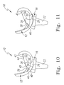
- the tibial tray 14 may be implanted at a 7° posterior inclination, as shown in FIGS. 10 and 11 .
- the anterior cam 38 of the femoral component 12 engages the anterior cam 46 of the spine 36 at about 6° of hyperextension.
- the anterior cam 38 of the femoral component 12 engages the anterior cam 46 of the spine 36 at different degrees of hyperextension based on the angle of posterior inclination of the tibial tray 14 (and hence the bearing 16).
- the cams 38, 46 will engage one another at 3° of hyperextension when the tibial tray 14 (and hence the bearing 16) is implanted at a 10° posterior inclination, or at 13° of hyperextension when the tibial tray 14 (and hence the bearing 16) is implanted at a 0° posterior inclination (see, e.g., FIGS. 6-9 ).
- anterior cam 38 of the femoral component 12 and the anterior cam 46 of the spine 36 are configured to cause the femoral component 12 to roll anteriorly relative to the bearing 16 at ranges of hyperextension beyond when the cams 38, 46 contact one another.
- the cam faces of the anterior cams 38, 46 are configured such that rolling contact exists between the femoral component 12 and the bearing 16 during hyperextension of the knee prosthesis 10 beyond initial contact of the cams 38, 46 to a point where the patient's soft tissues prevent further hyperextension of the prosthesis 10.
- the femoral component 14 may roll anteriorly relative to the bearing 16 through a fairly wide range of hyperextension.
- the femoral component 14 may roll anteriorly relative to the bearing 16 through up to 18°-25° of hyperextension when the tibial tray 14 is implanted at a 0° posterior inclination (see, e.g., FIGS. 6-9 ). As shown in FIGS.
- the patient's soft tissues will typically prevent further hyperextension of the prosthesis 10 than from about 11° to about 18° of hyperextension (and perhaps less depending on the particular anatomy and/or condition of the patient's soft tissue).
- the posterior cam 42 of the femoral component 12 and the posterior cam 50 of the spine 36 cooperate to provide posterior roll-back during flexion of the knee.
- the posterior femoral cam 42 engages the posterior tibial cam 50 at about 50° of flexion.
- the posterior tibial cam 50 prevents further anterior translation of the femoral component 12.
- the posterior femoral cam 42 engages the posterior tibial cam 50 and roll-back occurs.
- the femoral condyle surfaces 30, 32 articulate within a range of about ⁇ 1 mm of the lowest point, i.e., the dwell point 58, of the bearing surfaces 26, 28 of the bearing 16.
- the dwell point 58 of the bearing 16 is relatively centrally located with the bearing surfaces 26, 28. In the exemplary embodiment described herein, the dwell point 58 is located within ⁇ 5% of the middle of the arc length of the bearing surfaces 26, 28.
- the posterior femoral cam 42 engages the posterior tibial cam 50 thereby preventing anterior slide of the femoral component 12. From this point through about 75° of flexion, the configuration of the cams 42, 50 allow the femoral component to roll back while articulating within the range of about ⁇ 1 mm of the dwell point 58. At about 75° of flexion, the configuration of the cams 42, 50 forces the femoral component 12 to roll posterior on the bearing 16.
- the contact point 60 of the condyle surfaces 30, 32 translates about 2 mm posteriorly from the dwell point 58.
- the contact point 60 of the condyle surfaces 30, 32 translates about 3 mm posteriorly from the dwell point 58 (see FIG. 17 ).
- the contact point 60 of the condyle surfaces 30, 32 translates about 5 mm posteriorly from the dwell point 58.
- the contact point 60 of the condyle surfaces 30, 32 translates about 7 mm posteriorly from the dwell point 58 (see FIG. 19 ).
- initial contact between the cams 42, 50 may occur at any point from about 40° to about 60° of flexion.
- roll in flexion may occur at any point from about 70° to about 90° of flexion.
- the distance the contact point 60 translates posteriorly from the dwell point 58 may also be varied from the exemplary values described above.
- the contact point 60 may translate from about 1 mm to about 2.5 mm posterior of the dwell point 58.
- the contact point 60 may translate from about 2 mm to about 3.5 mm posterior of the dwell point 58.
- the contact point 60 may translate from about 3 mm to about 5 mm posterior of the dwell point 58.
- the contact point 60 may translate from about 4 mm to about 7.5 mm posterior of the dwell point 58.
- the platform 18 of the tibial tray 14 has an upper surface 62 (upon which the bearing 16 is supported) which mates with a downwardly extending anterior surface 64 along and anterior edge 66.
- an imaginary line 68 may be drawn which is tangent to the lateral condyle surface 30 and intersects the anterior edge 66 of the platform 18 of the tibial tray 14.
- an imaginary line 68 may also be drawn which is tangent to the medial condyle surface 32 and intersects the anterior edge 66 of the platform 18 of the tibial tray 14.
- both imaginary lines 68 appear as a single line.
- the bearing 16 is positioned posteriorly of the other components of the prosthesis. Specifically, the anterior-most aspect of the bearing 16 is positioned posteriorly of the imaginary lines 68 throughout movement of the knee prosthesis 10. As such, when viewed in the side elevational views of FIGS. 20-23 , no portion of the bearing 16 intersects the imaginary lines 68 throughout the range of motion of the knee prosthesis 10. For example, at 120° of flexion (see FIG. 23 ), the anterior-most point of the bearing 16 is positioned posteriorly of the imaginary lines 68. Such a configuration reduces, or even prevents, contact of the bearing 16 with the surrounding soft tissue thereby potentially reducing occurrences of hemoarthrosis.
Landscapes
- Health & Medical Sciences (AREA)
- Orthopedic Medicine & Surgery (AREA)
- Physical Education & Sports Medicine (AREA)
- Cardiology (AREA)
- Oral & Maxillofacial Surgery (AREA)
- Transplantation (AREA)
- Engineering & Computer Science (AREA)
- Biomedical Technology (AREA)
- Heart & Thoracic Surgery (AREA)
- Vascular Medicine (AREA)
- Life Sciences & Earth Sciences (AREA)
- Animal Behavior & Ethology (AREA)
- General Health & Medical Sciences (AREA)
- Public Health (AREA)
- Veterinary Medicine (AREA)
- Prostheses (AREA)
Applications Claiming Priority (2)
| Application Number | Priority Date | Filing Date | Title |
|---|---|---|---|
| US866381 | 1992-04-10 | ||
| US10/866,381 US7731755B2 (en) | 2004-06-11 | 2004-06-11 | Posterior stabilized mobile bearing knee |
Publications (2)
| Publication Number | Publication Date |
|---|---|
| EP1604623A1 EP1604623A1 (en) | 2005-12-14 |
| EP1604623B1 true EP1604623B1 (en) | 2008-06-25 |
Family
ID=34975211
Family Applications (1)
| Application Number | Title | Priority Date | Filing Date |
|---|---|---|---|
| EP05253045A Active EP1604623B1 (en) | 2004-06-11 | 2005-05-18 | Posterior stabilized mobile bearing knee |
Country Status (8)
| Country | Link |
|---|---|
| US (1) | US7731755B2 (da) |
| EP (1) | EP1604623B1 (da) |
| JP (1) | JP4606946B2 (da) |
| AT (1) | ATE398986T1 (da) |
| AU (1) | AU2005202172B2 (da) |
| DE (1) | DE602005007655D1 (da) |
| DK (1) | DK1604623T3 (da) |
| ES (1) | ES2308399T3 (da) |
Cited By (14)
| Publication number | Priority date | Publication date | Assignee | Title |
|---|---|---|---|---|
| US8690954B2 (en) | 2011-11-18 | 2014-04-08 | Zimmer, Inc. | Tibial bearing component for a knee prosthesis with improved articular characteristics |
| US10188530B2 (en) | 2010-12-17 | 2019-01-29 | Zimmer, Inc. | Provisional tibial prosthesis system |
| US10195041B2 (en) | 2010-07-24 | 2019-02-05 | Zimmer, Inc. | Asymmetric tibial components for a knee prosthesis |
| US10265181B2 (en) | 2011-11-21 | 2019-04-23 | Zimmer, Inc. | Tibial baseplate with asymmetric placement of fixation structures |
| US10278827B2 (en) | 2015-09-21 | 2019-05-07 | Zimmer, Inc. | Prosthesis system including tibial bearing component |
| US10470889B2 (en) | 2010-07-24 | 2019-11-12 | Zimmer, Inc. | Asymmetric tibial components for a knee prosthesis |
| US10543099B2 (en) | 2010-07-24 | 2020-01-28 | Zimmer, Inc. | Tibial prosthesis |
| US10675153B2 (en) | 2017-03-10 | 2020-06-09 | Zimmer, Inc. | Tibial prosthesis with tibial bearing component securing feature |
| US10835380B2 (en) | 2018-04-30 | 2020-11-17 | Zimmer, Inc. | Posterior stabilized prosthesis system |
| US11324598B2 (en) | 2013-08-30 | 2022-05-10 | Zimmer, Inc. | Method for optimizing implant designs |
| US11324599B2 (en) | 2017-05-12 | 2022-05-10 | Zimmer, Inc. | Femoral prostheses with upsizing and downsizing capabilities |
| US11426282B2 (en) | 2017-11-16 | 2022-08-30 | Zimmer, Inc. | Implants for adding joint inclination to a knee arthroplasty |
| US11471288B2 (en) | 2010-09-10 | 2022-10-18 | Zimmer, Inc. | Motion facilitating tibial components for a knee prosthesis |
| US11786308B2 (en) | 2019-05-02 | 2023-10-17 | DePuy Synthes Products, Inc. | Orthopaedic implant placement system and method |
Families Citing this family (23)
| Publication number | Priority date | Publication date | Assignee | Title |
|---|---|---|---|---|
| US7875081B2 (en) * | 2006-09-25 | 2011-01-25 | New York Society For The Ruptured And Crippled Maintaining The Hospital For Special Surgery | Posterior stabilized knee prosthesis |
| KR100930727B1 (ko) * | 2008-01-08 | 2009-12-09 | 주식회사 코렌텍 | 개선된 포스트 및 개선된 캠 구조를 갖는 인공 슬관절 |
| US9788955B2 (en) * | 2008-02-18 | 2017-10-17 | Maxx Orthopedics, Inc. | Total knee replacement prosthesis with high order NURBS surfaces |
| US8187335B2 (en) | 2008-06-30 | 2012-05-29 | Depuy Products, Inc. | Posterior stabilized orthopaedic knee prosthesis having controlled condylar curvature |
| US8236061B2 (en) | 2008-06-30 | 2012-08-07 | Depuy Products, Inc. | Orthopaedic knee prosthesis having controlled condylar curvature |
| US8192498B2 (en) | 2008-06-30 | 2012-06-05 | Depuy Products, Inc. | Posterior cructiate-retaining orthopaedic knee prosthesis having controlled condylar curvature |
| US9168145B2 (en) | 2008-06-30 | 2015-10-27 | Depuy (Ireland) | Posterior stabilized orthopaedic knee prosthesis having controlled condylar curvature |
| US8828086B2 (en) | 2008-06-30 | 2014-09-09 | Depuy (Ireland) | Orthopaedic femoral component having controlled condylar curvature |
| US9119723B2 (en) | 2008-06-30 | 2015-09-01 | Depuy (Ireland) | Posterior stabilized orthopaedic prosthesis assembly |
| US8206451B2 (en) * | 2008-06-30 | 2012-06-26 | Depuy Products, Inc. | Posterior stabilized orthopaedic prosthesis |
| US8915965B2 (en) * | 2009-05-07 | 2014-12-23 | Depuy (Ireland) | Anterior stabilized knee implant |
| US8545571B2 (en) * | 2010-07-30 | 2013-10-01 | Howmedica Osteonics Corp. | Stabilized knee prosthesis |
| KR101255057B1 (ko) * | 2011-05-06 | 2013-04-16 | 주식회사 코리아본뱅크 | 인공 슬관절의 포스트-캠 구조 |
| KR101304446B1 (ko) | 2011-05-11 | 2013-09-05 | 심영복 | 인공 슬관절의 베어링부재 |
| US8968412B2 (en) | 2011-06-30 | 2015-03-03 | Depuy (Ireland) | Trialing system for a knee prosthesis and method of use |
| US8409293B1 (en) | 2011-10-26 | 2013-04-02 | Sevika Holding AG | Knee prosthesis |
| US9861491B2 (en) | 2014-04-30 | 2018-01-09 | Depuy Ireland Unlimited Company | Tibial trial system for a knee prosthesis |
| US10195056B2 (en) | 2015-10-19 | 2019-02-05 | Depuy Ireland Unlimited Company | Method for preparing a patient's tibia to receive an implant |
| US10537445B2 (en) | 2015-10-19 | 2020-01-21 | Depuy Ireland Unlimited Company | Surgical instruments for preparing a patient's tibia to receive an implant |
| CN108992215A (zh) * | 2018-08-14 | 2018-12-14 | 优适医疗科技(苏州)有限公司 | 新型膝关节假体 |
| EP3937855A1 (en) * | 2019-03-12 | 2022-01-19 | DePuy Ireland Unlimited Company | Orthopaedic system with insert having a post for medial pivoting of a femoral component |
| US11510784B2 (en) | 2019-09-10 | 2022-11-29 | Depuy Ireland Unlimited Company | Orthopaedic knee prosthesis system and methods for using same |
| US11883298B2 (en) | 2020-07-10 | 2024-01-30 | Depuy Ireland Unlimited Company | Medial stabilized orthopaedic knee prosthesis |
Family Cites Families (23)
| Publication number | Priority date | Publication date | Assignee | Title |
|---|---|---|---|---|
| US4085466A (en) * | 1974-11-18 | 1978-04-25 | National Research Development Corporation | Prosthetic joint device |
| US4298992A (en) * | 1980-01-21 | 1981-11-10 | New York Society For The Relief Of The Ruptured And Crippled | Posteriorly stabilized total knee joint prosthesis |
| FR2568467B1 (fr) | 1984-08-06 | 1989-06-23 | Benoist Girard Cie | Prothese d'articulation du genou. |
| US4888021A (en) * | 1988-02-02 | 1989-12-19 | Joint Medical Products Corporation | Knee and patellar prosthesis |
| US5007933A (en) * | 1989-01-31 | 1991-04-16 | Osteonics Corp. | Modular knee prosthesis system |
| US5147405A (en) * | 1990-02-07 | 1992-09-15 | Boehringer Mannheim Corporation | Knee prosthesis |
| US5358527A (en) * | 1991-03-22 | 1994-10-25 | Forte Mark R | Total knee prosthesis with resurfacing and posterior stabilization capability |
| US5330534A (en) * | 1992-02-10 | 1994-07-19 | Biomet, Inc. | Knee joint prosthesis with interchangeable components |
| US5549686A (en) * | 1994-06-06 | 1996-08-27 | Zimmer, Inc. | Knee prosthesis having a tapered cam |
| GB9415180D0 (en) * | 1994-07-28 | 1994-09-21 | Walker Peter S | Stabilised mobile bearing knee |
| US5702458A (en) * | 1994-12-09 | 1997-12-30 | New York Society For The Ruptured And Crippled Maintaining The Hospital For Special Surgery | Joint prosthesis |
| ATE202465T1 (de) | 1995-01-31 | 2001-07-15 | Sulzer Orthopaedie Ag | Gelenkprothese, insbesondere kniegelenkprothese |
| JP2965137B2 (ja) * | 1996-02-02 | 1999-10-18 | 瑞穂医科工業株式会社 | 人工膝関節 |
| US6325828B1 (en) * | 1997-12-02 | 2001-12-04 | Rose Biomedical Research | Apparatus for knee prosthesis |
| US6123729A (en) * | 1998-03-10 | 2000-09-26 | Bristol-Myers Squibb Company | Four compartment knee |
| US6080195A (en) * | 1998-07-08 | 2000-06-27 | Johnson & Johnson Professional, Inc. | Rotatable and translatable joint prosthesis with posterior stabilization |
| US6443991B1 (en) * | 1998-09-21 | 2002-09-03 | Depuy Orthopaedics, Inc. | Posterior stabilized mobile bearing knee |
| US6413279B1 (en) | 1999-03-01 | 2002-07-02 | Biomet, Inc. | Floating bearing knee joint prosthesis with a fixed tibial post |
| US6972039B2 (en) * | 1999-03-01 | 2005-12-06 | Biomet, Inc. | Floating bearing knee joint prosthesis with a fixed tibial post |
| US6475241B2 (en) * | 2000-03-13 | 2002-11-05 | Biomedical Engineering Trust I | Posterior stabilized knee replacement with bearing translation for knees with retained collateral ligaments |
| US6797005B2 (en) * | 2001-02-28 | 2004-09-28 | Biomedical Engineering Trust | Deep flexion posterior stabilized knee replacement with bearing translation |
| US6513279B1 (en) * | 2002-02-15 | 2003-02-04 | Carlos Hernandez | Chum dispenser for fishing |
| US20040054416A1 (en) * | 2002-09-12 | 2004-03-18 | Joe Wyss | Posterior stabilized knee with varus-valgus constraint |
-
2004
- 2004-06-11 US US10/866,381 patent/US7731755B2/en active Active
-
2005
- 2005-05-18 ES ES05253045T patent/ES2308399T3/es active Active
- 2005-05-18 DK DK05253045T patent/DK1604623T3/da active
- 2005-05-18 AT AT05253045T patent/ATE398986T1/de active
- 2005-05-18 EP EP05253045A patent/EP1604623B1/en active Active
- 2005-05-18 DE DE602005007655T patent/DE602005007655D1/de active Active
- 2005-05-19 AU AU2005202172A patent/AU2005202172B2/en not_active Ceased
- 2005-06-10 JP JP2005171256A patent/JP4606946B2/ja active Active
Cited By (29)
| Publication number | Priority date | Publication date | Assignee | Title |
|---|---|---|---|---|
| US11224519B2 (en) | 2010-07-24 | 2022-01-18 | Zimmer, Inc. | Asymmetric tibial components for a knee prosthesis |
| US10543099B2 (en) | 2010-07-24 | 2020-01-28 | Zimmer, Inc. | Tibial prosthesis |
| US10470889B2 (en) | 2010-07-24 | 2019-11-12 | Zimmer, Inc. | Asymmetric tibial components for a knee prosthesis |
| US10195041B2 (en) | 2010-07-24 | 2019-02-05 | Zimmer, Inc. | Asymmetric tibial components for a knee prosthesis |
| US11471288B2 (en) | 2010-09-10 | 2022-10-18 | Zimmer, Inc. | Motion facilitating tibial components for a knee prosthesis |
| US10188530B2 (en) | 2010-12-17 | 2019-01-29 | Zimmer, Inc. | Provisional tibial prosthesis system |
| US9655729B2 (en) | 2011-11-18 | 2017-05-23 | Zimmer, Inc. | Tibial bearing component for a knee prosthesis with improved articular characteristics |
| US10898337B2 (en) | 2011-11-18 | 2021-01-26 | Zimmer, Inc. | Tibial bearing component for a knee prosthesis with improved articular characteristics |
| US9655728B2 (en) | 2011-11-18 | 2017-05-23 | Zimmer, Inc. | Tibial bearing component for a knee prosthesis with improved articular characteristics |
| US9788954B2 (en) | 2011-11-18 | 2017-10-17 | Zimmer, Inc. | Tibial bearing component for a knee prosthesis with improved articular characteristics |
| US9925050B2 (en) | 2011-11-18 | 2018-03-27 | Zimmer, Inc. | Tibial bearing component for a knee prosthesis with improved articular characteristics |
| US9295558B2 (en) | 2011-11-18 | 2016-03-29 | Zimmer, Inc. | Tibial bearing component for a knee prosthesis with improved articular characteristics |
| US9204970B2 (en) | 2011-11-18 | 2015-12-08 | Zimmer, Inc. | Tibial bearing component for a knee prosthesis with improved articular characteristics |
| US8764838B2 (en) | 2011-11-18 | 2014-07-01 | Zimmer, Inc. | Tibial bearing component for a knee prosthesis with improved articular characteristics |
| US9186255B2 (en) | 2011-11-18 | 2015-11-17 | Zimmer, Inc. | Tibial bearing component for a knee prosthesis with improved articular characteristics |
| US9072607B2 (en) | 2011-11-18 | 2015-07-07 | Zimmer, Inc. | Tibial bearing component for a knee prosthesis with improved articular characteristics |
| US8690954B2 (en) | 2011-11-18 | 2014-04-08 | Zimmer, Inc. | Tibial bearing component for a knee prosthesis with improved articular characteristics |
| US8858643B2 (en) | 2011-11-18 | 2014-10-14 | Zimmer, Inc. | Tibial bearing component for a knee prosthesis with improved articular characteristics |
| US10265181B2 (en) | 2011-11-21 | 2019-04-23 | Zimmer, Inc. | Tibial baseplate with asymmetric placement of fixation structures |
| US11324598B2 (en) | 2013-08-30 | 2022-05-10 | Zimmer, Inc. | Method for optimizing implant designs |
| US11160659B2 (en) | 2015-09-21 | 2021-11-02 | Zimmer, Inc. | Prosthesis system including tibial bearing component |
| US10278827B2 (en) | 2015-09-21 | 2019-05-07 | Zimmer, Inc. | Prosthesis system including tibial bearing component |
| US10675153B2 (en) | 2017-03-10 | 2020-06-09 | Zimmer, Inc. | Tibial prosthesis with tibial bearing component securing feature |
| US11547571B2 (en) | 2017-03-10 | 2023-01-10 | Zimmer, Inc. | Tibial prosthesis with tibial bearing component securing feature |
| US11324599B2 (en) | 2017-05-12 | 2022-05-10 | Zimmer, Inc. | Femoral prostheses with upsizing and downsizing capabilities |
| US11426282B2 (en) | 2017-11-16 | 2022-08-30 | Zimmer, Inc. | Implants for adding joint inclination to a knee arthroplasty |
| US10835380B2 (en) | 2018-04-30 | 2020-11-17 | Zimmer, Inc. | Posterior stabilized prosthesis system |
| US11911279B2 (en) | 2018-04-30 | 2024-02-27 | Zimmer, Inc. | Posterior stabilized prosthesis system |
| US11786308B2 (en) | 2019-05-02 | 2023-10-17 | DePuy Synthes Products, Inc. | Orthopaedic implant placement system and method |
Also Published As
| Publication number | Publication date |
|---|---|
| ES2308399T3 (es) | 2008-12-01 |
| DE602005007655D1 (de) | 2008-08-07 |
| US20050278035A1 (en) | 2005-12-15 |
| EP1604623A1 (en) | 2005-12-14 |
| AU2005202172A1 (en) | 2006-01-05 |
| DK1604623T3 (da) | 2008-10-06 |
| AU2005202172B2 (en) | 2011-09-22 |
| ATE398986T1 (de) | 2008-07-15 |
| JP2006015133A (ja) | 2006-01-19 |
| US7731755B2 (en) | 2010-06-08 |
| JP4606946B2 (ja) | 2011-01-05 |
Similar Documents
| Publication | Publication Date | Title |
|---|---|---|
| EP1604623B1 (en) | Posterior stabilized mobile bearing knee | |
| EP2512380B1 (en) | Implant for restoring normal range of flexion and kinematics of the knee | |
| EP1400220B1 (en) | Posterior stabilized knee with varus-valgus constraint | |
| EP1684672B1 (en) | High flexion articular insert | |
| EP1333785B1 (en) | Floating bearing knee joint prosthesis with a fixed tibial post | |
| US6946001B2 (en) | Mobile bearing unicompartmental knee | |
| CA2072298C (en) | Rotational and translational bearing combination in biological joint replacement | |
| CA2449287C (en) | Femoral prosthesis | |
| US20140142713A1 (en) | Knee prosthesis assembly having proportional trochlear groove geometry | |
| EP1872747A1 (en) | Hinged orthopaedic prosthesis | |
| EP2083757A2 (en) | System and method for joint arthroplasty | |
| CA2254218C (en) | Prosthetic knee joint with enhanced posterior stabilization and dislocation prevention features | |
| AU2014200110A1 (en) | High flexion articular insert |
Legal Events
| Date | Code | Title | Description |
|---|---|---|---|
| PUAI | Public reference made under article 153(3) epc to a published international application that has entered the european phase |
Free format text: ORIGINAL CODE: 0009012 |
|
| AK | Designated contracting states |
Kind code of ref document: A1 Designated state(s): AT BE BG CH CY CZ DE DK EE ES FI FR GB GR HU IE IS IT LI LT LU MC NL PL PT RO SE SI SK TR |
|
| AX | Request for extension of the european patent |
Extension state: AL BA HR LV MK YU |
|
| 17P | Request for examination filed |
Effective date: 20060516 |
|
| AKX | Designation fees paid |
Designated state(s): AT BE BG CH CY CZ DE DK EE ES FI FR GB GR HU IE IS IT LI LT LU MC NL PL PT RO SE SI SK TR |
|
| 17Q | First examination report despatched |
Effective date: 20061115 |
|
| GRAP | Despatch of communication of intention to grant a patent |
Free format text: ORIGINAL CODE: EPIDOSNIGR1 |
|
| GRAS | Grant fee paid |
Free format text: ORIGINAL CODE: EPIDOSNIGR3 |
|
| GRAA | (expected) grant |
Free format text: ORIGINAL CODE: 0009210 |
|
| AK | Designated contracting states |
Kind code of ref document: B1 Designated state(s): AT BE BG CH CY CZ DE DK EE ES FI FR GB GR HU IE IS IT LI LT LU MC NL PL PT RO SE SI SK TR |
|
| REG | Reference to a national code |
Ref country code: GB Ref legal event code: FG4D |
|
| REG | Reference to a national code |
Ref country code: CH Ref legal event code: EP |
|
| REF | Corresponds to: |
Ref document number: 602005007655 Country of ref document: DE Date of ref document: 20080807 Kind code of ref document: P |
|
| REG | Reference to a national code |
Ref country code: IE Ref legal event code: FG4D |
|
| REG | Reference to a national code |
Ref country code: SE Ref legal event code: TRGR |
|
| PG25 | Lapsed in a contracting state [announced via postgrant information from national office to epo] |
Ref country code: SI Free format text: LAPSE BECAUSE OF FAILURE TO SUBMIT A TRANSLATION OF THE DESCRIPTION OR TO PAY THE FEE WITHIN THE PRESCRIBED TIME-LIMIT Effective date: 20080625 |
|
| PG25 | Lapsed in a contracting state [announced via postgrant information from national office to epo] |
Ref country code: PL Free format text: LAPSE BECAUSE OF FAILURE TO SUBMIT A TRANSLATION OF THE DESCRIPTION OR TO PAY THE FEE WITHIN THE PRESCRIBED TIME-LIMIT Effective date: 20080625 |
|
| REG | Reference to a national code |
Ref country code: ES Ref legal event code: FG2A Ref document number: 2308399 Country of ref document: ES Kind code of ref document: T3 |
|
| PG25 | Lapsed in a contracting state [announced via postgrant information from national office to epo] |
Ref country code: IS Free format text: LAPSE BECAUSE OF FAILURE TO SUBMIT A TRANSLATION OF THE DESCRIPTION OR TO PAY THE FEE WITHIN THE PRESCRIBED TIME-LIMIT Effective date: 20081025 Ref country code: LT Free format text: LAPSE BECAUSE OF FAILURE TO SUBMIT A TRANSLATION OF THE DESCRIPTION OR TO PAY THE FEE WITHIN THE PRESCRIBED TIME-LIMIT Effective date: 20080625 Ref country code: CZ Free format text: LAPSE BECAUSE OF FAILURE TO SUBMIT A TRANSLATION OF THE DESCRIPTION OR TO PAY THE FEE WITHIN THE PRESCRIBED TIME-LIMIT Effective date: 20080625 |
|
| PG25 | Lapsed in a contracting state [announced via postgrant information from national office to epo] |
Ref country code: RO Free format text: LAPSE BECAUSE OF FAILURE TO SUBMIT A TRANSLATION OF THE DESCRIPTION OR TO PAY THE FEE WITHIN THE PRESCRIBED TIME-LIMIT Effective date: 20080625 Ref country code: SK Free format text: LAPSE BECAUSE OF FAILURE TO SUBMIT A TRANSLATION OF THE DESCRIPTION OR TO PAY THE FEE WITHIN THE PRESCRIBED TIME-LIMIT Effective date: 20080625 Ref country code: PT Free format text: LAPSE BECAUSE OF FAILURE TO SUBMIT A TRANSLATION OF THE DESCRIPTION OR TO PAY THE FEE WITHIN THE PRESCRIBED TIME-LIMIT Effective date: 20081125 |
|
| PG25 | Lapsed in a contracting state [announced via postgrant information from national office to epo] |
Ref country code: EE Free format text: LAPSE BECAUSE OF FAILURE TO SUBMIT A TRANSLATION OF THE DESCRIPTION OR TO PAY THE FEE WITHIN THE PRESCRIBED TIME-LIMIT Effective date: 20080625 Ref country code: BG Free format text: LAPSE BECAUSE OF FAILURE TO SUBMIT A TRANSLATION OF THE DESCRIPTION OR TO PAY THE FEE WITHIN THE PRESCRIBED TIME-LIMIT Effective date: 20080925 |
|
| PLBE | No opposition filed within time limit |
Free format text: ORIGINAL CODE: 0009261 |
|
| STAA | Information on the status of an ep patent application or granted ep patent |
Free format text: STATUS: NO OPPOSITION FILED WITHIN TIME LIMIT |
|
| 26N | No opposition filed |
Effective date: 20090326 |
|
| PG25 | Lapsed in a contracting state [announced via postgrant information from national office to epo] |
Ref country code: IT Free format text: LAPSE BECAUSE OF FAILURE TO SUBMIT A TRANSLATION OF THE DESCRIPTION OR TO PAY THE FEE WITHIN THE PRESCRIBED TIME-LIMIT Effective date: 20080625 |
|
| PG25 | Lapsed in a contracting state [announced via postgrant information from national office to epo] |
Ref country code: MC Free format text: LAPSE BECAUSE OF NON-PAYMENT OF DUE FEES Effective date: 20090531 |
|
| REG | Reference to a national code |
Ref country code: CH Ref legal event code: PL |
|
| PG25 | Lapsed in a contracting state [announced via postgrant information from national office to epo] |
Ref country code: LI Free format text: LAPSE BECAUSE OF NON-PAYMENT OF DUE FEES Effective date: 20090531 Ref country code: CH Free format text: LAPSE BECAUSE OF NON-PAYMENT OF DUE FEES Effective date: 20090531 |
|
| PG25 | Lapsed in a contracting state [announced via postgrant information from national office to epo] |
Ref country code: GR Free format text: LAPSE BECAUSE OF FAILURE TO SUBMIT A TRANSLATION OF THE DESCRIPTION OR TO PAY THE FEE WITHIN THE PRESCRIBED TIME-LIMIT Effective date: 20080926 |
|
| PG25 | Lapsed in a contracting state [announced via postgrant information from national office to epo] |
Ref country code: LU Free format text: LAPSE BECAUSE OF NON-PAYMENT OF DUE FEES Effective date: 20090518 |
|
| PG25 | Lapsed in a contracting state [announced via postgrant information from national office to epo] |
Ref country code: HU Free format text: LAPSE BECAUSE OF FAILURE TO SUBMIT A TRANSLATION OF THE DESCRIPTION OR TO PAY THE FEE WITHIN THE PRESCRIBED TIME-LIMIT Effective date: 20081226 |
|
| PG25 | Lapsed in a contracting state [announced via postgrant information from national office to epo] |
Ref country code: TR Free format text: LAPSE BECAUSE OF FAILURE TO SUBMIT A TRANSLATION OF THE DESCRIPTION OR TO PAY THE FEE WITHIN THE PRESCRIBED TIME-LIMIT Effective date: 20080625 |
|
| PG25 | Lapsed in a contracting state [announced via postgrant information from national office to epo] |
Ref country code: CY Free format text: LAPSE BECAUSE OF FAILURE TO SUBMIT A TRANSLATION OF THE DESCRIPTION OR TO PAY THE FEE WITHIN THE PRESCRIBED TIME-LIMIT Effective date: 20080625 |
|
| PGFP | Annual fee paid to national office [announced via postgrant information from national office to epo] |
Ref country code: SE Payment date: 20150512 Year of fee payment: 11 Ref country code: FI Payment date: 20150512 Year of fee payment: 11 Ref country code: ES Payment date: 20150413 Year of fee payment: 11 Ref country code: DK Payment date: 20150512 Year of fee payment: 11 |
|
| PGFP | Annual fee paid to national office [announced via postgrant information from national office to epo] |
Ref country code: NL Payment date: 20150510 Year of fee payment: 11 Ref country code: AT Payment date: 20150427 Year of fee payment: 11 |
|
| REG | Reference to a national code |
Ref country code: FR Ref legal event code: PLFP Year of fee payment: 12 |
|
| REG | Reference to a national code |
Ref country code: DK Ref legal event code: EBP Effective date: 20160531 |
|
| REG | Reference to a national code |
Ref country code: NL Ref legal event code: MM Effective date: 20160601 |
|
| REG | Reference to a national code |
Ref country code: AT Ref legal event code: MM01 Ref document number: 398986 Country of ref document: AT Kind code of ref document: T Effective date: 20160518 |
|
| PG25 | Lapsed in a contracting state [announced via postgrant information from national office to epo] |
Ref country code: FI Free format text: LAPSE BECAUSE OF NON-PAYMENT OF DUE FEES Effective date: 20160518 |
|
| PG25 | Lapsed in a contracting state [announced via postgrant information from national office to epo] |
Ref country code: AT Free format text: LAPSE BECAUSE OF NON-PAYMENT OF DUE FEES Effective date: 20160518 Ref country code: SE Free format text: LAPSE BECAUSE OF NON-PAYMENT OF DUE FEES Effective date: 20160519 Ref country code: NL Free format text: LAPSE BECAUSE OF NON-PAYMENT OF DUE FEES Effective date: 20160601 |
|
| REG | Reference to a national code |
Ref country code: FR Ref legal event code: PLFP Year of fee payment: 13 |
|
| PG25 | Lapsed in a contracting state [announced via postgrant information from national office to epo] |
Ref country code: DK Free format text: LAPSE BECAUSE OF NON-PAYMENT OF DUE FEES Effective date: 20160531 |
|
| REG | Reference to a national code |
Ref country code: FR Ref legal event code: PLFP Year of fee payment: 14 |
|
| PG25 | Lapsed in a contracting state [announced via postgrant information from national office to epo] |
Ref country code: ES Free format text: LAPSE BECAUSE OF NON-PAYMENT OF DUE FEES Effective date: 20160519 |
|
| REG | Reference to a national code |
Ref country code: ES Ref legal event code: FD2A Effective date: 20181204 |
|
| PGFP | Annual fee paid to national office [announced via postgrant information from national office to epo] |
Ref country code: FR Payment date: 20220408 Year of fee payment: 18 |
|
| PGFP | Annual fee paid to national office [announced via postgrant information from national office to epo] |
Ref country code: BE Payment date: 20220420 Year of fee payment: 18 |
|
| PGFP | Annual fee paid to national office [announced via postgrant information from national office to epo] |
Ref country code: GB Payment date: 20230330 Year of fee payment: 19 |
|
| PGFP | Annual fee paid to national office [announced via postgrant information from national office to epo] |
Ref country code: IE Payment date: 20230412 Year of fee payment: 19 Ref country code: DE Payment date: 20230331 Year of fee payment: 19 |
|
| REG | Reference to a national code |
Ref country code: BE Ref legal event code: MM Effective date: 20230531 |