Technical Field
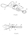
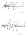
The present invention relates to a clip and a clipping
equipment for biological tissues, which are used as a treating
equipment for an endoscope for ligating a bleeding site in a
biological tissue, stitching a laceration, and marking in
excision of a mucosal tissue with an endoscope.
Background Technique
A clip used as a treating equipment for an endoscope is used
in many cases, such as ligating a bleeding site, stitching a
laceration, and marking in excision of a mucosal tissue with
an endoscope. A clipping equipment for biological tissues
disclosed in Japanese Utility Model Application Laid-Open
(JP-U) No.62-170010 is constructed of a clip 801 having opening
habit, a clip securing ring 802 for closing a clip tip part,
and a connecting plate 803 which is detachable on an operating
wire in which a hook is attached to a tip (not shown), as shown
in Fig. 35. In this clipping equipment 800 for biological
tissues, when the clipping equipment holds a biological tissue
such as a lesion, a connecting plate 803 is attached to a hook,
an opened tip part of a clip 801 is pushed against a lesion
with an endoscope, an operating wire positioned at a cavity
of an operating member is pulled, thereby, a clip 801 is moved
so that it is pulled into a clip securing ring 802, thereby,
an opening part is closed to clip a lesion. And, since a clip
801 clips a lesion with an opening part on a tip side, a force
directed to a basal direction of a clip 801 is exerted on a
clip securing ring 802. However, when a biological tissue is
ligated once, it is usually necessary to maintain the state
where the tissue is clipped for about a few days to one week
and, if a tissue immediately comes off, a tissue must be ligated
again with a clip. Such the second time treatment is pain to
a patient.
In addition, in order to prevent a connecting plate 803 from
protruding from a clip securing ring 802, and preventing a clip
801 from coming out from a hook in the state where a clip 801
has not completely been closed, a gel-like fixing agent 804
is filled into a clip securing ring 802. However, it is
difficult to fill into a cavity of a small clip securing ring
802 from a viewpoint of manufacturing and, upon clipping a
biological tissue, there is a problem that a fixing agent 804
filled into a cavity of a clip securing ring 802 is peeled and
fallen.
Japanese Patent Application Laid-Open (JP-A) No.50-75797
discloses a tissue clipping equipment for grasping a tissue
in a body with a clip using an endoscope, and dwelling the clip
therein. Since in this clipping equipment, a clip is directly
mounted on a hook provided on a tip of an operating wire, there
is a problem that, when a clip is dwelled, a clipping equipment
must be moved forwardly and backwardly, and left and right in
order to remove a clip from a hook, thus, a way to use it is
troublesome.
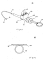
JP-U No. 2-6011 discloses a clipping equipment 900 which
overcomes the aforementioned disadvantage, as shown in Fig.
36. This clipping equipment 900 is equipped with a hook 902
provided on a tip of an operating wire 901, and a connecting
member 903 having an engaging pore 904 engaging with a pin 906
of a hook 902 on one end, and having a crook (not shown) which
is connected to a clip and is deformable by stretching on the
other end, wherein when a connecting plate 903 is moved to a
hand side via an operating wire 901 in order to dwell a clip
905 in a biological tissue, a crook of a connecting plate 904
is stretched, and the engaging state of a clip 905 and a
connecting plate 903 is released.
Although this clipping equipment 900 improved troublesome
operation of removing a clip from a hook, since a connecting
plate 903 is engaged with an operating wire 901 also after clip
dwelling, a connecting plate 903 must be removed after taken
out from an endoscope, and there is a problem of disposal of
a connecting plate 903 which has become an unnecessary part.
In addition, there is a problem that, since a connecting plate
903 is small, it is sucked into a sucking port of an endoscope
rarely, and this becomes a cause for worse suction. In
addition, as a common problem of clipping equipments described
in JP-A No. 50-75797 and JP-U No.2-6011, there is a problem that,
when a clip is mounted on a clipping equipment, since a hook
is a cantilevered type, balance is worse, and a clip is easily
detached from a hook.
On the other hand, JP-U No.1-77703 shows a clipping equipment
in which a ratchet mechanism consisting of an engaging claw
and a claw to be engaged of a ratchet is applied. This clipping
equipment is such that a pitch of a claw to be engaged is formed
finer than that of an engaging claw, or at least two sets of
an engaging claw and a claw to be engaged are disposed, and
a phase of one of them is shifted without altering a pitch of
a claw, and a moving pitch is small-sized as a whole, in which
by pulling a wire fixing a clip, and opening a clip to a greatest
degree and further pulling a wire, a clip is closed and, finally,
a connecting plate is destructed, releasing a clip.
According to this clipping equipment, a movement amount of
an operating member can be operated finer by a ratchet mechanism.
However, since attachment of a clip and operation of opening
are performed by a ratchet mechanism, there is a problem that,
in order to assuredly stop a clip at an intended position, an
operator must perform position adjusting operation while
seeing a clip, and operation is troublesome.
In addition, in a clipping equipment 900 described in JP-U
No.2-6011, since operation of engaging with a pin 906 of a hook
and a small engaging pore 904 of a connecting plate 903 is
performed in a dim endoscope chamber, it is difficult to mount
a clip 905. In addition, since a handle is operated in the
state where a pin 906 is engaged into an engaging pore 904,
a pin 906 is detached during handle operation in some cases.
Further, in many cases where a lesion must be grasped with a
clip, it is difficult to perform rapid operation.
In addition, JP-A No.2000-335631 discloses a clip packaging
body for an endoscope in which a clip for an endoscope can be
accommodated between substrates. According to this endoscope
packaging body, when sterilization treatment is performed in
a packaging body in advance, sterilization working becomes
easy. However, in order to mount a clip on a clipping equipment
from this clip packaging body for an endoscope, it is necessary
to grasp a clip by one hand from above the packaging body in
the state where a clip packaging body for an endoscope is opened
half, so that a clip is not directly contacted with a hand,
and hang a pin of a hook on a small engaging pore of a connecting
plate in the state where two members of a handle and an operating
member are grasped by the other hand. Such the operation needs
a skill and is troublesome.
Therefore, an object of the present invention is to provide
a treating equipment clip for an endoscope which can assuredly
clip a lesion over a long period of time, in ligating a bleeding
site of a biological tissue, stitching a laceration, and
marking in excision of a mucosal tissue with an endoscope. In
addition, another object of the present invention is to provide
a clipping equipment for a biological tissue which does not
need seeing a degree of opening of a clip and does not need
fine positioning adjustment. In addition, other object of the
present invention is to provide a clipping equipment for a
biological tissue which does not need troublesome operation
for mounting and removing a clip.
Disclosure of the Invention
That is, the present invention provides a clip comprising a
self-opening clip body having a clipping part on a tip and
provided with a twin-arm part extending from a basal part, and
a securing ring, wherein the self-opening clip body has a first
concave part on a clip basal part, and a second concave part
between the first concave part and a clip tip part, respectively,
the securing ring is mounted on the first concave part, and
is sliding-moved from a mounting position of a first concave
part with an external force to be mounted on a second concave
part, thereby, said clip is used as a treating equipment for
an endoscope of closing a clipping part at a tip of the clip
body.
Also, the present invention provides a clipping equipment for
a biological tissue equipped with an outer tube which can be
inserted into a biological cavity, an operating member freely
passed through the outer tube, an operating wire freely passed
through the operating member, and a self-opening holder which
can be opened and closed by the action of the operating member
attached to a tip of the operating wire.
Also, the present invention provides a clip holder having one
or two or more clip accommodating grooves for accommodating
a clip comprising a self-opening clip body having a clipping
part on a tip and equipped with a twin-arm part extending from
a basal part, and a securing ring freely moving in a tip
direction which is mounted in a concave part of the basal part,
in the state where said clip is sunk with its tip facing
downwardly.
Brief Description of the Drawings
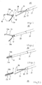
Fig. 1 is a perspective of a clip of an embodiment of the present
invention, Fig. 2 is a view showing the closed state of a clip
of Fig. 1, Fig. 3 is a cross-sectional view showing use aspect
of a clip of Fig. 1, Fig. 4 is a perspective showing a part
of a tip side of a clipping equipment for a biological tissue
of the present example, Fig. 5 is a view showing the state where
a clip is mounted, Fig. 6 is a view showing the state where
a clip is closed, Fig. 7 is a view showing the state where a
closed clip is detached, Fig. 8 is a cross-sectional view of
a tip side of a clip equipment omitting description of a clip,
Fig. 9 is a longitudinal cross-sectional view of Fig. 6, Fig.
10 is a view showing a variation example of a clipping equipment
for a biological tissue of the present example, Fig. 11 is a
perspective showing a part of a clipping equipment for a
biological tissue in a second embodiment, Fig. 12 is a
cross-sectional view showing a part of a clipping equipment
for a biological tissue of the present example, Fig. 13 is an
exploded view of a clipping equipment for a biological tissue
of the present example, Fig. 14 is an enlarged view omitting
a part of a bar-like member, Fig. 15 is an enlarged view of
an operating wire, Fig. 16 is a view in which an operating wire
of Fig. 15 is seen from an upper side, Fig. 17 (A) is a view
showing an abutment relationship between an operating member
and a sliding short casing, (B) is a view in which the equipment
is seen along with an A-A line of (A), Fig. 18 (B) is a front
view showing a part of a handle axis which is a member
constituting a clip equipment of the present example (A) is
a left side view of (B), Fig. 19 (B) is a front view of a rotation
body which is a member constituting a clip equipment of the
present example, (A) is a left side view of (B), (C) is a right
side view of (B), Fig. 20 (B) is a front view of a position
holding means which is a member constituting a clipping
equipment of the present example, (A) is a left side view of
(B), Fig. 21 (B) is a front view of a stopping means which is
a member constituting a clipping equipment of the present
example, (A) is a left side view of (B), Fig. 22 is a
longitudinal cross-sectional view for explaining each
operating step of a clipping equipment of the present example,
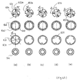
Fig. 23 is a view for explaining movement of a rotation body,
Fig. 24 is a perspective of a clipping equipment for a
biological tissue in a third embodiment, Fig. 25 is a front
view of a mounting equipment which is mounted on a clipping
equipment for a biological tissue of the present example, Fig.
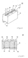
26 is a perspective of a clip holder, Fig. 27 is a
cross-sectional view of a clip holding member, Fig. 28 is a
view for explaining a method of using a clipping equipment for
a biological tissue of the present example, Fig. 29 is a view
showing the state where a clip is held, Fig. 30 is a view showing
the state where a clip is accommodated in an external casing,
Fig. 31 is a view showing the state where a clip having a closed
tip is detached from a holder, Fig. 32 is a perspective of other
clip holder, Fig. 33 and Fig. 34 are cross-sectional views for
explaining a method of using other clip holder, Fig. 35 is a
cross-sectional view of a part of the previous clipping
equipment, and Fig. 36 is a perspective of a part of the previous
other clipping equipment.
Best Mode for Carrying Out the Invention
In a clipping equipment for a biological tissue (hereinafter,
simply also referred to as "clipping equipment") of the present
invention and a clip, a tip side refers to a biological tissue
side in the use state, and a basal side refers to a side opposite
to a biological tissue. A clip in an embodiment of the present
invention will be explained by referring to Fig. 1 to Fig. 3.
As shown in Fig. 1 and Fig. 2, a clip 10 of the present example
comprises a clip body 1 obtained by bending an elongate metal
plate spring at a central part, and a cylindrical securing ring
2. A clip body 1 comprises clipping parts 3,3 for clipping
a biological tissue on a tip, a basal part 4 exhibiting a
generally U-shaped cross section, and twin- arm parts 11,11
having self-opening property on a tip which extend from a basal
part 4. Since a metal plate spring constituting a clip body
is movably inserted in a cavity of an operating member described
later, a width size w thereof is restricted.
A clip body 1 has a first concave part 5 on a basal part 4,
and second concaves 6,6 between a first concave part 5 and a
clip tip part, respectively, and a securing ring 2 is mounted
on a first concave part 5. As a site for mounting a first
concave part 5 in a basal part, such a position is preferable
that a space in which a tip of a holder 8 can be hung on a
generally U-shaped cross-sectional part 41 is possessed, and
opening of a clip tip in the opened state cannot be narrowed.
In addition, a site for mounting a second concave part 6 is
not particularly limited as far as it is between a first concave
part 5 and a clip tip part, and clipping parts 3,3 of a clip
tip are tightly abutted thereagainst. In the present example,
by providing a plate width ramp 69 on a tip side of a second
concave part 6, and making a basal side from a ramp 69 a concave
part, when a securing ring 2 is sliding-moved from a mounting
position in a first concave part 5 with an external force, it
is assuredly mounted in a second concave part 6. It is
preferable that a concave degree of a second concave part 6
of a clip body is larger than a concave degree of a first concave
part 5 in that a securing ring 3 can be ensured. In addition,
in clipping parts 3,3 at a clip tip, it is preferable that a
tip part of a twin-arm part is bent inwardly and, at the same
time, an irregular part is provided on its abutting surface
in that a biological tissue can be tightly clipped.
In a clip 10, a holder 3 on a tip is usually opened as shown
in Fig. 1 and, in this state, a securing ring 2 is mounted on
a first concave part 5 of a basal part 4. Since a cavity part
of a securing ring 2 is hung on a recess part, a securing ring
2 mounted in a first concave part 5 is not naturally moved
forwardly and backwardly as far as an external force is exerted,
and is not slipped on a tip side, not narrowing an opening width
of a clipping part 3. Examples of a material for a clip include
stainless steel, and titanium. In addition, a length of an
arm part of a clip is not particularly limited, but is
preferably 2.0 to 6.0mm, particularly preferably 3.0 to 5.0mm.
When the length is within the aforementioned range,
particularly, holding property of a clip is excellent.
Then, a method of clipping a biological tissue with a clip
10 will be explained. First, a pair of self-opening arm-like
holders 8 which is attached to a tip of an operating wire 7
of a clipping equipment are hung on an internal side of a
generally U-shaped cross sectional part 41 of a basal part 4
of a clip 1. Then, when an operating wire 7 which is in a cavity
of an operating member 9 and can be moved forwardly and
backwardly is pulled, holders 8 are pulled into a cavity of
an operating member 9, and a securing ring 2 is abutted against
a tip 91 of an operating member 9. By further pulling an
operating wire 7, a twin-arm part 11 of an clip body is gradually
pulled into a cavity of a securing ring 2 from a basal part
side of a clip and, when pulled until a position of a second
concave part 6, a step 69 and a securing ring 2 are abutted,
thereby, a securing ring 2 is stopped, clipping parts 3,3 at
a tip of a clip body 1 are abutted into the state where a
biological tissue (not shown) is clipped (Fig.2). Then, when
an operating wire 7 is pushed in a direction opposite to pulling
of an operating wire 7, that is, forwardly, a self-opening
holder 8 is automatically come out from a basal part 4 of a
clip. On the other hand, since a securing ring 2 is fixed firm
in a recess part of a second concave part 6, a clip body 1 in
the closed state can assuredly clip a biological tissue to be
clipped regardless of a size thereof, the tissue is not come
out therefrom, and the state where a biological tissue is
clipped can be maintained over a long period of time.
As a material for a clip body 1, a metal such as stainless
steel and a titanium alloy, and a plastic such as an ABS resin,
a rigid vinyl chloride resin, polyamide and polyethylene are
preferable in that they are not corroded in a cavity,
particularly, in stomach in which a digestion enzyme is
secreted. In addition, a material rich in elasticity is
preferable in that, upon clipping of a biological tissue, a
clipping part 3 at a clip tip is brought into the closed state
from the opened state, and is it necessary to retain the closed
state for a long period of time. In addition, a material for
a securing ring is not particularly limited, but the ring is
used together with a clip body 1, and examples of the material
include the same material as that of a clip body 1.
Specifically, a plastic such as fluorine resin, polyamine, and
a silicone resin, and a metal such as stainless steel, and a
titanium alloy are preferable.
According to a clip 10 of the present embodiment example, a
biological tissue such as a lesion can be assuredly clipped
over a long period of time.
A clipping equipment for a biological tissues in the first
embodiment of the present invention will be explained by
referring to Fig.4 to Fig.10. A clipping equipment 20 for a
biological tissue in an embodiment of the present example is
equipped with an outer tube 21 which can be inserted into a
biological cavity, an operating member 22 freely passed
through the outer tube 21, an operating wire 23 freely passed
though the opening member 22, a self-opening holder 24 which
can be opened and closed by the action of the operating member
attached to a tip of the operating wire 23, and a self-opening
clip 10a having a clipping member for clipping a biological
tissue which is attached to a tip of the holder 24 in a
detachable manner by opening/closing the holder. For example,
a basal part of an operating wire 23 is connected to a handle
(not shown).
In a clipping equipment 20 for a biological tissue, a material
for an operating member 22 is not particularly limited, but
examples include a thermoplastic resin such as polyether ether
ketone, polyamide, and polyimide, and a thin metal coil. A
thermoplastic resin is preferable in that it can assuredly
transmit movement of an operating handle to a tip side, and
a thin metal coil is preferable in that although a gap is formed
by bending or pulling, bending property and rigidity are
excellent. An external diameter of an operating member 22 is
not particularly limited, but is preferably 1.7 to 2.7mm,
particularly preferably 1.9 to 2.3mm.
An operating wire 23 has a holder 24 fixed at a tip, and has
a connecting part 25 having a slightly larger diameter that
of a wire body which is equipped with a step 26. In addition,
at a position apart from a tip of an operating member 22 to
a basal side by a stroke of an operating member, and on an
internal wall of an operating member 22, a stopper 27 through
which an operating wire body can inserted and which is abutted
against a step 26 is attached, preventing excessive protrusion
of an operating member 22, and preventing a holder 24 from
excessively entering an operating member 22. A material for
an operating wire 23 is not particularly limited, but a material,
a whole or a part of which has flexibility, is preferable.
Specific examples include a metal wire such as stainless steel,
and carbon steel, and a resin fiber such as polyamide, polyether,
and ultra high molecular weight polyethylene.
An outer tube 21 is a hollow continuous flexible member. An
internal diameter of an external casing 21 is not particularly
limited, but is preferably 1.8 to 2.8mm, particularly
preferably 2.0 to 2.4mm. When an internal diameter is within
the aforementioned range, operating property is particularly
excellent. In addition, a length of an external casing 21 is
not particularly limited, but is preferably 1,500 to 3,000mm,
particularly preferably 1,600 to 2, 300mm. When the length is
within the aforementioned range, operating property in an
endoscope is particularly excellent. A material for an
external case 21 is not particularly limited, but examples
include a fluorine resin such as polytetrafluoroethylene
(PTFE), and a tetrafluoroethylene-hexafluoropropylene
copolymer resin (FEP).
In a clipping equipment 20 for a biological tissue, a clip
10a is not particularly limited as far as it is equipped with
a self-opening twin-arm part 11a, and a securing ring 12 for
closing a clipping part 15 of a twin-arm part 11a as shown in
Fig.4, but a clip 10 shown in Fig.1 and Fig.2 is preferable.
A method of mounting a clip 10a in a clipping equipment 20
for a biological tissue by the aforementioned construction
will be explained. For example, in the state of Fig.4, an
operating wire 23 is fixed at an operating handle and, by
pulling an operating handle, an operating member 22 is moved
on a holder 24 side in a direction of an axis line of an operating
wire 23. Thereby, a holder 24 consisting of a pair of arm parts
enters a basal side while contacting with an internal
circumferential surface of an operating member 22, therefore,
is gradually being closed. And, a tip hook 28 of an operating
member 22 is closed, clipping a basal part 14 of a clip 10a
to retain a clip 10a. Further, by pulling an operating handle,
a securing ring 12 is abutted against a tip of an operating
member 22, and then a securing ring 12 is abutted against a
step 13 which is between both arm parts of a clip 10a, closing
clipping parts 15,15 of a clip (Fig.6, Fig.9). By returning
an operating member 22 to an original position from this state,
a holder 24 is protruded from an operating member 22,
self-opening property possessed by a holder 24 makes a pair
of arm parts in the opened state, and a clip 10a while it is
opened can be detached.
According to a clipping equipment 20 for a biological tissue,
complicated operating is not necessary in mounting or
detaching a clip. In addition, when a clip 10a is retained
by a holder 24, even if an operating member 22 is moved slightly,
since a holder 24 is still accommodated in a cavity of an
operating member 22, and tip hooks 28 are overlaid each other,
a clip 10a is not easily fallen. In addition, even when a gap
between tip hooks 28 is slightly opened, since a plate of a
U-shaped cross section 41 of a basal part 4 of a clip 10a has
an extent of a width, a clip 10a is not fallen from a holder
24.
In a clipping equipment 20 for a biological tissue, a shape
of a holder 24 is not limited to the aforementioned generally
V-letter shape, but for example, a generally U-letter shape
24a as shown in Fig.10 suffices. By curving an arm part of
a holder 24a, a load applied to a connecting part 25 accompanied
with shape change can be dispersed, spring characteristic is
improved and, further, a tip part can be closed more rapidly
as compared with a linear-like state. As a curved shape, any
shape can be adopted in view of a time of opening and closing
motion of a twin-arm part, and spring characteristic.
In addition, a method of operating member 22 and an operating
wire 23 is not limited to the aforementioned method, but
examples include a method of fixing an operating wire 23, and
moving an operating member 22, and a method of moving both of
an operating wire 23 and an operating member 22.
According to a clipping equipment 20 for a biological tissue,
since complicating procedure such as mounting and detachment
of a clip is not necessary, the equipment is extremely useful
as a clipping equipment for a biological tissue which is used
in marking for making clear a region where treatment such as
ligation and excision of a bleeding site of a biological tissue.
Then, a clipping equipment for a biological tissue in a second
embodiment will be explained by referring to Fig.11 to Fig.23.
In Fig.12, description of a sliding cylinder 211 of Fig.11 is
omitted. In a clipping equipment 30 for a biological tissue
of the present example, the same symbol is added to the same
component as that of the clipping equipment 20 for a biological
tissue in the first embodiment example, explanation thereof
is omitted, and different points will be mainly explained.
That is, in a clipping equipment 30 for a biological tissue,
a different point from a clip equipment 20 for a biological
tissue is in that the equipment further has a handle 51 for
controlling an operating member, and a first forcing mechanism
for forwarding a handle 51 and, at the same time, stopping
forwarding of a handle 51, a retaining mechanism for retaining
a stoppage position of a handle 51 once, a second forcing
mechanism for further forwarding from a stoppage position of
a handle 51 and, at the same time, stopping forwarding of a
handle, and a returning mechanism by which a handle 51 is
automatically returned to a position before first forcing are
provided. That is, a clipping equipment 30 consists of an
external casing 21, a hollow sliding cylinder 211 which is
connected to an external casing 21 on a tip side, and provided
with a connecting flange 213 on a basal side, an equipment body
part 61 equipped with a main chamber in which a tip side part
is fitted into a cavity of a sliding cylinder 211, a stopping
means situated on a tip side which is mounted in a main chamber
of an equipment body part 61 in the fixed state, a position
retaining means 64 which is mounted in a main chamber adjacent
to a stopping means 63 on a basal side in the fixed state, a
handle 51 which is inserted into an equipment body part 61 from
a basal side, and a bar-like member 71 in which one end on a
basal side is abutted against a back of a substrate 651 of a
rotation body 65, and the other end is protruded from a tip
side of an equipment body part 61.
A handle 51 consists of a ring-like clipping part 511, and
a handle axis 512 in which one end is connected to a clipping
part 511 and the other end is equipped with a crown-like first
cam part 514. A clipping part 511 is operated by an operator
by grasping with a hand, and has such an extent of a space that
a finger of an operator can be inserted. A first cam part 514
is a ring-like projection having 6 triangular projections in
which valley parts are formed every 60 degree on an end face
of a cylindrical member. A first cam part 514 engages with
three engaging feathers 653 of a rotation body 65 which moves
in a stopping means 63 and in a position retaining means 64,
and imparts a forwarding force and a rotating force to a
rotation body 65. In the figure, for drawing reason, there
is a different form around a connecting part of a ring-like
clipping part 511 and a handle axis 512.
A position retaining means 64 is a cylindrical member which
is fixed in a main chamber 615 of an equipment body part 61,
determines a position of accommodation of a rotation body 65
in the state before operation, guides forwarding of a rotation
body 65 by first forcing operation and, at the same time, leads
a rotation body to a position of initiation of second forcing.
On an internal circumferential surface 644, three fitting
groves 641 in which three plate-like feather members 653 of
a rotation body 65 are fitted are formed along with a
longitudinal direction. In addition, on a circumferential
edge of an opening on a tip end, a cam group 642 equipped with
6 saw blade cross section-shaped notches 645 is attached. When
a tip of a feather member 653 of a rotation body is abutted
against an inclined surface of a notch 645 by spring power,
a cam groove 642 imparts rotation of maximum 60 degree. An
inclined surface of a notch 645 is formed as a descending
inclination in a counterclock direction seen from a tip side.
A stopping means 63 is a cylindrical member which is fixed
adjacent to a tip side of a position retaining means 64 in a
main chamber of an equipment body part 61, stops a entering
rotation body 65 by first forcing operation and, at the same
time, guides entrance of a rotation body 65 by second forcing
operation. A stopping means 63 has three ribs 631 extending
from a tip side to a midway in an axial direction on an internal
circumferential surface (length of symbol m of Fig.22). Three
ribs 631 are formed at an interval of 120 degree, and one rib
is formed at a position at 50 degree counterclockwisely
relative to a vertical axis seen from a tip side. A stopping
means 63 is such that a tip opening is abutted against a wall
of a main chamber in the state where it is disposed in a main
chamber of an equipment body part 61. For this reason, a
rotation body 65 is not protruded from a stopping means 63 in
a tip direction. A length 1 of a stopping means 63 is a
forwarding stroke of a rotation body 65.
A rotation body 65 is fitted with a first cam part 514 at a
tip of a handle axis, and is forwarded, retreated or rotated
in a position retaining means 64 and a stopping means 63 to
transmit an operating force to a bar-like member 71. A
rotation body 65 has a substrate 651 positioned at a tip side
which has notches 654 at a 120 degree pitch, and a second cam
part 654 having one end on a basal side thereof of a sharp cross
section shape with a plate-like feather member 653 which
extends in an axial direction, at the same time, is attached
at a 120 degree pitch between notches 654, on a substrate 651.
In addition, the body has an engaging pore 655 with which a
tip part 731 of a bar-like member 71 is engaged, on a center
of a back of a substrate 651.
A bar-like member 71 has a holder 24 attached at a tip, and
is equipped with an operating wire 23 in which a basal end is
fixed at a fixing ring part 73, an operating member 22 having
a cavity in which an operating wire 23 is inserted, and having
a regulating part 741 on a basal end, and a sliding short casing
75 in which a window part 751 is formed on an external
circumferential surface of a cylindrical casing abutting with
a regulating part 741 on a basal side. A basal part 751 of
a sliding short casing 75 is engaged with an engaging pore 655
on a back of a substrate 651 of a rotating body. A fixing ring
part 73 is fixed on a tip side slightly from a main chamber
of an equipment body part 61, and is not interlocked with
operation of a handle. A fixing ring part 73 of an operating
wire 23 is slidably fitted in a window part 751 of a sliding
short casing 75. An operating member 22 is forwarded against
spring power of a spring 74 via a sliding short casing 75 by
forwarding of a rotation body 65 (forwarding of a handle 51)
and, when a rotation body 65 is retreated by spring power of
a spring 74, the member is retreated interlocking therewith.
In addition, since an operating wire 23 is freely inserted into
an operating member 22, and a connecting part 733 on a basal
side is slided in a window part 751 of a sliding short casing
75, this is not interlocked with operation of a handle 51
(movement of an operating member 22).
An interior of an equipment body part 61 has, in an order from
a tip side, a tip opening 616 in which an operating member 22
comes in and out, a chamber 614 for accommodating a spring 74,
a fixing part 617 at which a fixing ring part 73 of a bar-like
member is fixed, a main chamber 615 in which a stopping means
63 and a position retaining means 64 are accommodated, and an
inserting port 616 in which a tip of a handle axis is inserted.
In an equipment body part 61, a first flange part 611, and a
second flange part 612 are attached to a cylindrical body from
a basal side, to enhance operating property.
A sliding cylinder 211 is a member for operating forwarding
and retreating of a hollow external casing 21, and is a
cylindrical entity which is fitted at a tip part of an equipment
body part 611. A tip side is connected to a hollow external
casing 21 which is inserted into a biological cavity, and a
fixing flange 213 having a convex part (not shown) fitting in
a concave part 613 of an equipment body part is provided on
a basal side. An engagement releasing means 214 for releasing
engagement between a slide cylinder 211 and an equipment body
61 is attached to a fixing flange 213. An operating member
22 is inserted into an external casing 21. And, a sliding
cylinder 211 mounted on an equipment body part 61 is such that,
when operation of pulling a handle 51 in the state where
engagement with an equipment body part 61 is released, or
forcing a sliding cylinder 21 therein is performed, an external
casing 21 is forwarded to an operating member 22. Thereby,
a twin-arm part of a clip 10a is closed, and can be transiently
accommodated in an external casing 21 in the state where a clip
10a is closed. Thereby, when an external casing 21 is inserted
into an endoscope, since a clip 10a is accommodated in an
external casing 21, a forceps pore of an endoscope is not
damaged.
Then, a method of operating a clipping equipment 30 of a second
embodiment example will be explained below by referring to
mainly Fig.22 and Fig.23. A method of operating a clipping
equipment 30 comprises first forcing operation, retaining step,
second forcing operation and returning step. In first forcing
operation, when a handle 51 is pushed, a first cam part 514
at a tip of a handle and a second cam part 654 of a rotation
body 65 are abutted (Fig.22 (a) and Fig.23 (a)). In this case,
a first cam part 514 and a second cam part 654 are arranged
so that mutual mountain-like top parts of cam parts are slightly
slipped. Therefore, a mountain-like top part 515 of a first
cam part 514 at a tip of a handle is forwarded while abutting
against a mountain-like inclination of a second cam part 654
of a rotation body. And, a rotation body 65 is forwarded from
a position retaining means 64 to a stopping means 63. When
a rotation body 65 enters a stopping means 63, a first cam part
514 and a second cam part 654 are completely engaged, and a
rotation body 65 is rotated from an original position by 30
degree counterclockwisely (first rotation). In this state,
since a substrate 651 of a rotation body is in a relation that
the substrate is abutted with a rib 631 of a stopping means
63, a rotation body 65 is moved by a stroke n, runs against
an end face of a rib 631, and is stopped (Fig.22(b) and
Fig.23(b)). By first forcing operation, an operating member
22 of a bar-like member 71 which is interlocked with movement
of a rotation 65 is forwarded, a holder 24 is pulled into an
operation member 22 to close a tip of a holder 24, making a
holder 24 retain a clip 10a (Fig.5).
In a retaining step, after first forcing operation, when a
hand is released from a handle 51, a rotation body 65 is
retreated by an elastic force of a spring 74, and a second cam
part of a rotation body 65 and a cam groove 642 of a position
retaining means are engaged. Thereupon, a tip of a second cam
part of a rotation part 65 is rotated from an original position
by 60 degree counterclockwisely along with inclination of saw
blade-like cam groove 642 (second rotation), and is stopped
in a valley part of a cam groove 642 (Fig. 22(c) and Fig. 23(c)).
Thereby, the state where an opened clip 10a is retained at a
tip of a holder 24 can be maintained. In addition, since an
opening degree of a clip 10a is constant, position adjustment
by fine handle procedure becomes unnecessary.
In second forcing operation, when a handle 51 is pushed from
the retention state, a first cam part 514 of a handle axis and
a second cam part of a rotation body are engaged, and a rotation
body 65 is further rotated from an original position by 90
degree (third position). In this state, a notch part 654 of
a rotation part 65 and a rib 631 of a stopping means 63 are
in a fitting positional relationship. In this state, when a
handle 51 is forced, a rotation body 65 is forwarded to a tip
of a stopping means 63 (Fig.22 (d) and Fig.23 (d)). By second
forcing operation, an operating member 22 of a bar-like member
71 which is interlocked with movement of a rotation body 65
is further forwarded by a stroke m, closing a clipping part
15 of a clip 10a (Fig.6).
In a returning step, after second forcing operation, when a
hand is released from a handle 51, an operating member 22 is
returned by elastic action of a spring 74 and, interlocking
therewith, fitting between a rotation body 65, a feather member
653, and a rib 631 of a stopping means 63 is released, a tip
of a rotation body 65 comes to a spiral cam groove 642, is
further moved along with its inclination, and is stopped at
a valley part, rotating from an original position by 120 degree
counterclockwisely (forth rotation). In this state, a feather
member 653 of a rotation body 65 and a groove 641 of a position
retaining means 64 are positioned so that they are fitted. For
this reason, a rotation body 65 is automatically returned to
an original position. Since by a returning step, an operating
member 22 is returned to an original position, a tip of a
self-opening holder is opened, and a clip 10a is detached from
a holder 24. On the other hand, a clip of 10a is still closed,
and mounting of a biological tissue on a clip 10a is completed.
In a clipping equipment 30 of a second embodiment example,
an operating method is not limited to the aforementioned method
of fixing an operating wire 23, and moving an operating member
22 by seeing relatively, but by reversing a position of a spring,
and directions of a rotation body, a stopping means, and a
position retaining means, an operation member may be fixed,
and an operating wire may be moved. Alternatively, by changing
shapes of a rotation body, a stopping means, and a position
retaining means, multi-stage stoppage, and position retaining
may be performed.
According to a clipping equipment 30 of a second embodiment
example, when ligation and excision of a bleeding site of a
biological tissue with an endoscope are performed, since it
is not necessary to see an extent of opening of a clip with
an endoscope, and fine position adjustment wit handle
operation becomes unnecessary, a treatment time can be
shortened. Alternatively, by imparting a stoppage position
having a constant moving distance, a tip of an endoscope
treating equipment can be put in and out by a constant amount.
Then, a clipping equipment in accordance with a third
embodiment will be explained by referring to Fig. 24 to Fig.31.
In a clipping equipment 40 in a third embodiment, the same
symbol is added to the same component as that of the clipping
equipment 30 in a second embodiment, explanation thereof will
be omitted, and different points will be mainly explained.
That is, a different point from a clipping equipment 30 in a
clipping equipment 40 is in that a clip retaining member 90
is attached to an external circumferential surface of an
equipment body part 61 near a second flange 612. A clip
retaining member 90 is a block body 91, and has three of clip
accommodating grooves 92 for accommodating a tip of a clip 10
downwardly in the sunk state, and generally cross grooves 94
consisting of guide grooves 93 which run straight through a
center of an accommodating group 92, in a direction orthogonal
with an accommodating groove 92. In addition, an engaging
groove 94 which engages with a mounting equipment 80 is formed
on a back of a block body 91. By closing one end of an engaging
groove 94 to be a wall, positioning becomes easy. That is,
when a plate-like engaging piece 81 of a mounting equipment
is completely engaged with an engaging groove 94, a clip
retaining member 90 is situated approximately at a center of
an equipment body part 61.
A clip accommodating groove 92 is slightly larger than a plate
width of a twin-arm part 11, and is slightly wider from a deepest
part towards a surface. A depth of a clip accommodating groove
92 is such a depth that a basal part is slightly seen in the
state where a clip 10 is accommodated, and a groove length of
clip accommodating groove 92 is slightly smaller than a width
by which a clip 10 is opened in the natural state. Thereby,
upon accommodation of a clip 10 in an accommodating groove 92,
since a twin-arm part is slightly closed, stable accommodation
is possible. A shape of a guide groove 93 is not particularly
limited, but in the present example, by adopting an
alloy-shaped groove when seen in a plane surface, a tip hook
28 of a holder 24 is easily guided to a generally U-shaped part
41 of a basal part of a clip. A guide groove 93 colored with
a light emitting paint is preferable in that a guide groove
93 can be recognized even in a dark endoscope chamber. The
number of clip accommodating grooves 92 which are formed into
a block body 91 is 1, 2 or 4 or more in addition to the
aforementioned 3. A material for a clip retaining member 90
is not particularly limited, but when a transparent material
is used, this is preferable in that weather a clip 10 is
accommodated or not can be observed from the outside. Examples
of a transparent material include a resin material such as
acrylonitrile·butadiene·styrene resin (ABS resin),
polyethylene, polystyrene, polycarbonate, and acryl resin.
When a clip retaining member 90 is accommodated in a sterilized
bag (not shown) in the state where a clip 10 is accommodated
in an accommodating groove 92, this is preferable in that it
is not necessary to perform sterilization treatment every
operation, and operating property is excellent.
A mounting equipment 80 is an adapter for attaching a clip
holding member 90 to a cylindrical body of an equipment body
part 61. A mounting equipment 80 consists of a ring part 82
which is mounted on a equipment body part 61, and a plate-like
engaging piece 82 which engages with an engaging groove 94 of
a clip holding member 90 having a jaw part 82 provided above
a ring part 82.
Then, a method of performing hemostasis using a clipping
equipment 40 will be explained by referring to Fig. 28 to Fig. 31.
In Fig.28, description of a flange 213 of a sliding cylinder
211 is omitted. First, a clip holding member 90 is removed
from a sterilized bag in the state where a clip 10 is
accommodated in an accommodating groove 92, and is fixed to
an equipment body part 61. While a tip part of an external
casing 21 is grasped by a hand, a tip of a holder 24 is pushed
against a guide groove 93 of a clip holding member 90. In this
case, since a hand is not directly contacted with a clip 10,
there is no fear of pollution.
Then, when first forcing operation is performed by pushing
a handle 51, an operating member 22 is forwarded, a tip of holder
24 provided at a tip of an operating wire 23 is closed, and
a basal part 4 of a clip 10 is held (Fig.28, Fig.29). This
operation can be simply operated only by grasping a handle 51
by one hand, and grasping an outer tube 21 by the other hand.
In addition, by simple operation of forcing a tip of a holder
24 into a guide groove 93, a clip 10 can be attached to a holder
24. At a tip side of an operating member 22, a ring part 29
abutting against a securing ring 2 is provided. An external
diameter of a ring part 29 is approximately the same as an
external diameter of a securing ring 2, and a securing ring
2 can be forwarded by forwarding an operating member 22.
In this state, engagement between an equipment body part 61
and a sliding cylinder 211 is released, and a handle 51 is pulled
towards a basal side. Thereby, an operating member 22 is
pulled towards a basal side relative to an external casing 21,
and a clip 10 is transiently accommodated in an external casing
21 in the state where a tip thereof is closed (Fig.30). In
this state, an external casing 21 is passed through an endoscope
(not shown), and a whole endoscope is inserted near a bleeding
site in a living body. And, while an endoscope is confirmed,
an external casing 21 is protruded from a tip of an endoscope.
Then, when a handle 51 is pushed into a tip side, since an
operating member 22 is forwarded relative to an external casing
21, a clip 10 is protruded from an external casing 21, and a
tip becomes in the opened state. Then, a clop 10 having an
opened tip is pushed against an objective site. And, when
second forcing operation is performed by further pushing a
handle 51, an operating member 22 is forwarded to push a
securing ring 2 of a clip towards a tip side. Thereby, a
securing ring 2 is engaged with a second concave part 6 of a
clip 10, to clip an objective site of a living body. Since
a securing ring 2 which has been pushed out by an operating
member 22 is engaged with a second concave part 6, the closed
state of a clip is maintained. After a clip 10 is closed, when
a hand is released from a handle 51, a handle 51 is returned
to an original position by a returning mechanism. Thereupon,
since an operating member 22 is also retreated, a holder 24
is opened, and a closed clip 10 can be detached from a holder
24 (Fig.31). And, while a clip 10 is dwelled in a body, a holder
24 together with an endoscope is extracted from a body. When
a site clipped with a clip 10 is necrotized, a clip 10 is
naturally detached, and is excreted from a body.
Then, a variation example of a clip holding member 90 will
be explained by referring to Fig.32 to Fig.34. In a clip
holding member 90a, the same symbol is added to the same
component as that of a clip holding member 90, explanation
thereof will be omitted, and different points will be mainly
explained. That is, in a clip holding member 90a, a different
point from a clip holding member 90 is a point in that the number
of general cross grooves is one, a point in that a guide groove
93a is an inclination which runs straight passing through a
center of an accommodating groove and descends towards a center,
a depth at a central part of a guide groove is such that the
central part is above a securing ring 2 in the state where a
clip 10 is accommodated, and the holder is hung on a generally
U-shaped basal part of the clip, and a point in that mounting
is not on an external circumferential surface of an equipment
body part 61, but on a separate member from a clipping equipment.
Examples of a form of a guide groove 93 include a fan shape
in addition to the aforementioned alloy shape and rectangular
shape when seen on a plane surface.
Then, a method of removing a clip 10 accommodated in a clip
holding member 90a will be explained. Fig.33 is a
cross-sectional view of Fig.32, and Fig.34 is a view showing
the state where a holder 24 is closed in Fig.33. A tip of a
holder 24 is pushed against a guide groove 93a of a clip holding
member 90a on which a clip 10 is mounted. In this state, by
moving an operating member 22 to a clip holding member 90a side,
the state where a clip 10 is held by a holder 24 is obtained
(Fig.34). Then, a clip 10 is removed from a clip holding member
90a, and mounting of a clip 10 on a clipping equipment is
completed.
According to a clipping equipment 40 of a third embodiment
example, the same operation as that of a clipping equipment
30 of a second embodiment example is performed and,
additionally, by simple operation of grasping a handle 51 by
one hand, grasping an external casing 21 by the other hand,
and forcing a tip of a holder 24 into a guide groove 93, a clip
10 can be attached to a holder 24. For this reason, even an
operator who is not familiar with this operation can perform
clip mounting operation simply and efficiently.
Industrial Applicability
The clip and the clipping equipment of the present invention
are extremely useful as a treating equipment which is used in
ligating a bleeding site of a biological tissue, stitching a
laceration, and marking in excision of a mucosal tissue with
an endoscope.