EP1604611A1 - Puncture device - Google Patents
Puncture device Download PDFInfo
- Publication number
- EP1604611A1 EP1604611A1 EP04721375A EP04721375A EP1604611A1 EP 1604611 A1 EP1604611 A1 EP 1604611A1 EP 04721375 A EP04721375 A EP 04721375A EP 04721375 A EP04721375 A EP 04721375A EP 1604611 A1 EP1604611 A1 EP 1604611A1
- Authority
- EP
- European Patent Office
- Prior art keywords
- moving member
- lancing device
- space
- housing
- advancing direction
- Prior art date
- Legal status (The legal status is an assumption and is not a legal conclusion. Google has not performed a legal analysis and makes no representation as to the accuracy of the status listed.)
- Granted
Links
Images




Classifications
-
- A—HUMAN NECESSITIES
- A61—MEDICAL OR VETERINARY SCIENCE; HYGIENE
- A61B—DIAGNOSIS; SURGERY; IDENTIFICATION
- A61B5/00—Measuring for diagnostic purposes; Identification of persons
- A61B5/15—Devices for taking samples of blood
- A61B5/151—Devices specially adapted for taking samples of capillary blood, e.g. by lancets, needles or blades
- A61B5/15186—Devices loaded with a single lancet, i.e. a single lancet with or without a casing is loaded into a reusable drive device and then discarded after use; drive devices reloadable for multiple use
-
- A—HUMAN NECESSITIES
- A61—MEDICAL OR VETERINARY SCIENCE; HYGIENE
- A61B—DIAGNOSIS; SURGERY; IDENTIFICATION
- A61B5/00—Measuring for diagnostic purposes; Identification of persons
- A61B5/15—Devices for taking samples of blood
- A61B5/150007—Details
- A61B5/150015—Source of blood
- A61B5/150022—Source of blood for capillary blood or interstitial fluid
-
- A—HUMAN NECESSITIES
- A61—MEDICAL OR VETERINARY SCIENCE; HYGIENE
- A61B—DIAGNOSIS; SURGERY; IDENTIFICATION
- A61B5/00—Measuring for diagnostic purposes; Identification of persons
- A61B5/15—Devices for taking samples of blood
- A61B5/150007—Details
- A61B5/150053—Details for enhanced collection of blood or interstitial fluid at the sample site, e.g. by applying compression, heat, vibration, ultrasound, suction or vacuum to tissue; for reduction of pain or discomfort; Skin piercing elements, e.g. blades, needles, lancets or canulas, with adjustable piercing speed
- A61B5/150061—Means for enhancing collection
- A61B5/150099—Means for enhancing collection by negative pressure, other than vacuum extraction into a syringe by pulling on the piston rod or into pre-evacuated tubes
-
- A—HUMAN NECESSITIES
- A61—MEDICAL OR VETERINARY SCIENCE; HYGIENE
- A61B—DIAGNOSIS; SURGERY; IDENTIFICATION
- A61B5/00—Measuring for diagnostic purposes; Identification of persons
- A61B5/15—Devices for taking samples of blood
- A61B5/150007—Details
- A61B5/150374—Details of piercing elements or protective means for preventing accidental injuries by such piercing elements
- A61B5/150381—Design of piercing elements
- A61B5/150412—Pointed piercing elements, e.g. needles, lancets for piercing the skin
-
- A—HUMAN NECESSITIES
- A61—MEDICAL OR VETERINARY SCIENCE; HYGIENE
- A61B—DIAGNOSIS; SURGERY; IDENTIFICATION
- A61B5/00—Measuring for diagnostic purposes; Identification of persons
- A61B5/15—Devices for taking samples of blood
- A61B5/150007—Details
- A61B5/150374—Details of piercing elements or protective means for preventing accidental injuries by such piercing elements
- A61B5/150381—Design of piercing elements
- A61B5/150503—Single-ended needles
-
- A—HUMAN NECESSITIES
- A61—MEDICAL OR VETERINARY SCIENCE; HYGIENE
- A61B—DIAGNOSIS; SURGERY; IDENTIFICATION
- A61B5/00—Measuring for diagnostic purposes; Identification of persons
- A61B5/15—Devices for taking samples of blood
- A61B5/151—Devices specially adapted for taking samples of capillary blood, e.g. by lancets, needles or blades
- A61B5/15101—Details
- A61B5/15103—Piercing procedure
- A61B5/15107—Piercing being assisted by a triggering mechanism
- A61B5/15113—Manually triggered, i.e. the triggering requires a deliberate action by the user such as pressing a drive button
-
- A—HUMAN NECESSITIES
- A61—MEDICAL OR VETERINARY SCIENCE; HYGIENE
- A61B—DIAGNOSIS; SURGERY; IDENTIFICATION
- A61B5/00—Measuring for diagnostic purposes; Identification of persons
- A61B5/15—Devices for taking samples of blood
- A61B5/151—Devices specially adapted for taking samples of capillary blood, e.g. by lancets, needles or blades
- A61B5/15101—Details
- A61B5/15115—Driving means for propelling the piercing element to pierce the skin, e.g. comprising mechanisms based on shape memory alloys, magnetism, solenoids, piezoelectric effect, biased elements, resilient elements, vacuum or compressed fluids
- A61B5/15117—Driving means for propelling the piercing element to pierce the skin, e.g. comprising mechanisms based on shape memory alloys, magnetism, solenoids, piezoelectric effect, biased elements, resilient elements, vacuum or compressed fluids comprising biased elements, resilient elements or a spring, e.g. a helical spring, leaf spring, or elastic strap
-
- A—HUMAN NECESSITIES
- A61—MEDICAL OR VETERINARY SCIENCE; HYGIENE
- A61B—DIAGNOSIS; SURGERY; IDENTIFICATION
- A61B5/00—Measuring for diagnostic purposes; Identification of persons
- A61B5/15—Devices for taking samples of blood
- A61B5/151—Devices specially adapted for taking samples of capillary blood, e.g. by lancets, needles or blades
- A61B5/15186—Devices loaded with a single lancet, i.e. a single lancet with or without a casing is loaded into a reusable drive device and then discarded after use; drive devices reloadable for multiple use
- A61B5/15188—Constructional features of reusable driving devices
- A61B5/1519—Constructional features of reusable driving devices comprising driving means, e.g. a spring, for propelling the piercing unit
-
- A—HUMAN NECESSITIES
- A61—MEDICAL OR VETERINARY SCIENCE; HYGIENE
- A61B—DIAGNOSIS; SURGERY; IDENTIFICATION
- A61B5/00—Measuring for diagnostic purposes; Identification of persons
- A61B5/15—Devices for taking samples of blood
- A61B5/151—Devices specially adapted for taking samples of capillary blood, e.g. by lancets, needles or blades
- A61B5/15186—Devices loaded with a single lancet, i.e. a single lancet with or without a casing is loaded into a reusable drive device and then discarded after use; drive devices reloadable for multiple use
- A61B5/15188—Constructional features of reusable driving devices
- A61B5/15192—Constructional features of reusable driving devices comprising driving means, e.g. a spring, for retracting the lancet unit into the driving device housing
- A61B5/15194—Constructional features of reusable driving devices comprising driving means, e.g. a spring, for retracting the lancet unit into the driving device housing fully automatically retracted, i.e. the retraction does not require a deliberate action by the user, e.g. by terminating the contact with the patient's skin
Definitions
- the present invention relates to a device for sticking a needle into the skin to obtain a sample of body fluid such as blood or a tissue.
- a lancing device which includes a needle held by a moving member and a housing accommodating the moving member, the moving member being operated to advance the needle for puncturing the skin (see JP-A-H11-206742 and JP-A-2001-515377, for example).
- a lancing device applies negative pressure to the skin to make the skin congested and to widen the wound caused by the puncturing (see JP-A-2001-515377).
- a lancing device disclosed in JP-A-H11-206742 includes a needle 91 held by a moving member 90 which is advanced by a spring.
- the moving member 90 engages with a housing 92 and a coil spring 93 is compressed.
- the moving member 90 is released from the engagement with the housing 92, and then the resilient force of the coil spring 93 is applied to the moving member 90, thereby advancing the moving member 90 and the needle 91.
- the lancing device disclosed in JP-A-2001-515377 includes a needle 95 held by a moving member 94 which is advanced by pressure difference.
- the lancing device 9B when the moving member 94 is at a standby position, the space 92, in which the moving member 94 is held, is in a decompressed state, while the moving member 94 is supported by restoring force by a coil spring 97 (or bellows (not shown)) .
- the lancing device 9B further includes a contact portion 98 for contacting with skin S. The inside of the contact portion 98 is decompressed to apply negative pressure to the skin S.
- the user needs not to move the moving member 94 to bring the moving member 94 into the standby position, whereby the burden of the user is reduced.
- the contact portion 98 of the lancing device 9B does not intimately contact with the skin S, the air may flow into the contact portion 98 from between the skin S and the tip end of the contact portion 98.
- the pressure difference between the inside of the contact portion 98 and the space 96 is reduced, and accordingly the pressing force applied to the moving member 94 is reduced.
- the speed of the movingmember 94 and the needle 95 for puncturing is reduced.
- the contact state between the skin S and the tip end of the contact portion 98 depends on weather the skin S is hairy or not, there may be a variation in the amount of the air flow into the contact portion 98. In light of these, the pain resulting from the puncturing can be unbearable, depending on the punctured portion or the amount of the air flowing into the contact portion 98.
- An object of the present invention is to reduce the load of the user as well as to reduce pain of the patient on sampling body fluid or a tissue.
- a lancing device comprises a moving member for moving a needle in an advancing direction from a standby position to a puncturing position, and also comprises a housing allowing the movement of the moving member in the advancing direction and in a retreating direction opposite to the advancing direction.
- the moving member moves in close contact with the housing.
- the housing includes a first space which is offset in the retreating direction from a portion contacting with the moving member, and a second space offset in the advancing direction from the portion contacting with the moving member.
- the lancing device further comprises a fixing means for fixing the moving member to the housing at the standby position, with an urging force applied in the advancing direction.
- the device also comprises a disengaging means for dissolving the fixing of the moving member.
- the moving member is moved by the urging force in the advancing direction from the standby position.
- the urging force may be applied to the moving member by a resilient member.
- the resilient member is typically a coil spring or a bellows, and is made of foam or rubber, for example.
- the lancing device moves the moving member to the standby position by utilizing the pressure difference resulting in a suctioning force to the moving member in the retreating direction.
- the suctioning force is applied to the moving member by making the pressure in the first space smaller than the pressure in the second space beyond a predetermined value.
- the pressure in the first space may be made smaller than the atmospheric pressure by a predetermined value.
- the lancing device further comprises a negative pressure generating means for generating a negative pressure in the second space.
- the negative pressure generating means may apply negative pressure to the first and the second space individually.
- the negative pressure generating means may apply the negative pressure to the first space for causing a suctioning force to act on the moving member, thereby moving the moving member toward the standby position.
- the negative pressure generating means is typically an electrical pump.
- the negative pressure generating means may be a manually operable pump.
- air flow into the first space is caused before or on disengaging the moving member by the disengaging means.
- the air flow into the first space is caused when the moving member is disengaged by the disengaging means.
- the disengaging means comprises an operating portion to be operated to cause the disengaging means to act on the engaging means.
- the positional selection of the operating portion determines whether the first space is caused to communicate with outside or not to communicate with the outside.
- the operating portion is movable in the advancing direction and the retreating direction, with part thereof protruding out of the housing.
- the operating portion includes an engaging part accommodated in the housing.
- the housing is formed with a through-hole for allowing the movement of the operating portion in the advancing direction and in the retreating direction.
- the engaging part is used to select between a state in which the engaging portion closes the through-hole and another state in which the engaging portion does not close the through-hole.
- the second space is provided with a retreating means for moving the needle back in the retreating direction after the needle is brought to the puncturing position.
- a lancing device comprises a moving member for moving a needle in an advancing direction from a standby position to a puncturing position, and also comprises a housing for allowing the movement of the moving member in the advancing direction and in a retreating direction opposite to the advancing direction.
- a dividing wall is provided for dividing an inner space of the housing into a first space offset in the retreating direction and a second space offset in the advancing direction.
- the dividing wall may include a bellows.
- the lancing device further comprises a fixing means for fixing the moving member to the housing at the standby position, with an urging force applied in the advancing direction.
- the moving member is moved by the urging force in the advancing direction from the standby position.
- the urging force is applied to the moving member by at least one resilient member.
- the resilient member may be the bellows mentioned above, or may be a coil spring.
- the lancing device according to the present invention may apply the urging force to the moving member by the bellows serving as the dividing wall.
- the bellows may not be arranged to apply urging force to the moving member, but may serve only as the dividing wall.
- a lancet 2 is attached to a lancing device 1A in use.
- the lancet 2 includes a body 20a and a needle 20b protruding from the body.
- the needle 20b is made of e.g. metal, and the body 20a is made of e.g. synthetic resin.
- the needle 20b may be integrally embedded in the body 20a when the body is produced by insert molding, for example.
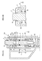
- the lancing device 1A includes a housing 3, a lancet holder 4, an operating cap 5, a case 6, and an electrical pump 7.
- the housing 3 accommodates the lancet holder 4.
- the housing 3 includes through-holes 30, 31, 32, projections 33, 34, a decompression space 35, and a contact portion 36.
- the through-hole 30 is used for discharging the air out of the decompression space 35.
- the through-hole 31 is used for discharging the air out of the contact portion 36.
- the through-hole 32 allows the movement of the operating cap 5, and is used for introducing the air into the decompression space 35.
- the projection 33 engages with the lancet holder 4 and coil springs 80, 81.
- the projection 34 provided at the contact portion 36 engages with a coil spring 82.
- the decompression space 35 is decompressed when the lancet holder 4 is engaged with the projection 33.
- the decompression space 35 is decompressed by discharging the air through the through-hole 30.
- the contact portion 36 comes into contact with skin S to be punctured.
- the inner space of the contact portion 36 is under negative pressure on puncturing so that the skin S is raised.
- the negative pressure is generated by discharging the air out of the contact portion 36.
- the lancet holder 4 for holding the lancet 2, is advanced toward a tip of the housing 3 (in the N1 direction) by pressing the operating cap 5.
- the lancet holder 4 is formed with a pair of claws 40, a recess 41, and flanges 42, 43.
- claws 40 can engage with an upper surface 33a of the projection 33 of the housing 3, and are resiliently movable toward and away from each other.
- the recess 41 holds the lancet 2.
- the coil spring 80 is arranged between the flange 42 and the projection 33 of the housing 3, while the coil spring 82 is arranged between the flange 42 and the projection 34.
- the coil spring 82 When the lancet holder 4 advanced, the coil spring 82 is compressed, and then the restoring force of the coil causes the lancet holder 4 to retreat.
- the coil spring 82 may be dispensed with.
- the flange 43 contacts with an inner surface of the housing 3 (an inner surface of the projection 33) when the lancet holder 4 moves.
- the flange 43 is provided with an O-ring 44.
- the operating cap 5 for advancing the lancet holder 4 is held in the housing 3 in a manner such that a portion of the cap protrudes from the through-hole 32.
- the operating cap 5 is provided with a flange 50 and a pair of pressing portions 51.
- the flange 50 causes the decompression space 35 of the housing 3 to communicate with the outside via the through-hole 32 or not to communicate with the outside.
- the lower surface of the flange 50 contacts with the upper end of the coil spring 81.
- the lower end of the coil spring 81 contacts with the upper surface 33a of the projection 33 of the housing 3.
- the coil spring 81 is arranged between the flange 50 and the projection 33.
- the pressing portions 51 press the claws 40, so that each end of the claws 40 comes closer to each other. In this state, the engagement (latching) of the claws 40 with the projection 33 is released, then as described above, the lancet holder 4 is advanced by the restoring force of the coil spring 80.
- the case 6 holds the housing 3 and the electrical pump 7.
- the case 6 is formed with paths 60, 61 for communicating the electrical pump 7 with the inside of the decompression space 35 and the contact portion 36 of the housing 3.
- the electrical pump 7 is controlled by a non-illustrated control means for discharging the air of the decompression space 35 and the contact portion 36 through the through-holes 30, 31 and the paths 60, 61.
- the electrical pump 7 includes a suctioning portion 70 for suctioning the air of the decompression space 35 through the through-hole 30 and the path 61, and a suctioning portion 71 for suctioning the air of the contact portion 36 through the through-hole 31 and the path 60, though the function is not illustrated.
- the control means of the electrical pump 7 switches between the suctioning state and the non-suctioning state of each of the suctioning portions 70, 71 individually.
- the claws 40 of the lancet holder 4 are brought into engagement or into latching with the upper surface 33a of the projection 33 of the housing 3, as shown in Fig. 2A.
- This latching is achieved when the decompression space 35 is decompressed by suctioning the air of the decompression space 35 at the suctioning portion 70 of the electrical pump 7 through the through-hole 30 and the path 61.
- the inner pressure of the contact portion 36 is the same as the atmospheric pressure. In this state, decompression of the decompression space 35 causes a pressure difference between the contact portion 36 and the decompression space 35.
- This pressure difference is increased as the decompression space 35 is decompressed, and works as a suctioning force to move the lancet holder 4 upwardly (in the N2 direction).
- the suctioning force applied to the lancet holder 4 becomes larger than the sum of the resistance force of the coil spring 80 and the transfer resistance of the lancet holder 4 against the housing 3, the lancet holder 4 can be moved upwardly (in the N2 direction).
- the restoring force of the coil spring 82 supports upward movement of the lancet holder 4.
- the claws 40 engages with the upper surface 33a of the projection 33 of the housing 3 to achieve the latching of the lancet holder 4.
- the lancet 2 is attached to the lancet holder 4.
- the attachment of the lancet 2 to the lancet holder 4 is performed by fitting the body 20a of the lancet 2, at the portion opposite to the needle 20b, to the recess 41.
- the contact portion 36 of the lancing device 1A is brought into contact with the skin S, and the skin S is raised by the negative pressure generated in the contact portion 36.
- the negative pressure is generated by suctioning the air of the contact portion 36 from the suctioning portion 71 of the electrical pump 7 through the through-hole 31 and the path 60.
- the lancet 2 is advanced in the N1 direction to puncture the skin S by the needle 20b.
- the operating cap 5 is pressed in the N1 direction to release the lancet holder 4 from latching.
- the flange 50 of the operating cap 5 When the operating cap 5 is pressed in the N1 direction, the flange 50 of the operating cap 5 is spaced from the upper wall 37 of the housing 3, whereby the air flows into the decompression space 35 through the through-hole 32 of the housing 3.
- the pressure in the decompression space 35 is increased and the pressure difference between the decompression space 35 and the contact portion 36 is reduced, thereby reducing the suctioning force applied to the lancet holder 4.
- the operating cap 5 can be lowered smoothly.
- the operating cap 5 is moved in the N1 direction over a predetermined distance to inwardly move the claws 40 toward each other, so that the claws 40 are disengaged from the upper surface 33a of the projection 33, as shown in Fig. 4A.
- the restoring force of the coil spring 80 advances the lancet holder 4 in the N1 direction, and then the needle 20b of the lancet 2 punctures the skin S.
- the lancet holder 4 retreats in the N2 direction due to the restoring force of the coil springs 80, 82, thereby immediately pulling out the needle 20b from the skin S.
- the negative pressure applied to the skin S causes the bleeding from the portion which is punctured by the needle 20b.
- the lancing device 1A utilizes the electrical pump 7 to apply the suctioning force to the lancet holder 4 so that the latching of the lancet holder 4 is achieved.
- the lancet holder 4 can be latched by an easy operation such as pressing operating buttons provided at the lancing device 1A, for example.
- Such structure facilitates troublesome operation for latching the lancet holder 4.
- the lancing device 1A utilizes the restoring force of the coil spring 80 to advance the lancet holder 4 in the N1 direction.
- the lancet holder 4 can be moved at a constant speed, without depending on the inner pressure of the contact portion 36. Due to the structure, even if the air flows into the contact portion 36 and thus the inner pressure of the contact portion 36 is increased, the lancet holder 4 and the needle 20b can be advanced as desired.
- the negative pressure is applied to the contact portion 36 before the needle 20b punctures the skin S.
- the decompression space 35 and the contact portion 36 may be decompressed by utilizing a manual pump, in place of the electrical pump 7.
- the air flow into the decompression space 35 may not necessarily be caused by pressing the operating cap 5.
- An operating button other than the operating cap 5 may be used to cause the air flow into the decompression space 35.
- the lancet holder 4 may be latched by increasing the inner pressure of the contact portion 36 and applying pressing force upwardly (in the N1 direction) from the contact portion 36 toward the lancet holder 4.
- the lancing device utilizes the restoring force of the coil spring for advancing the lancet holder.
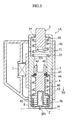
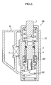
- the coil spring may be replaced with a bellows 80'.
- both a coil spring 80A and a bellows 80B may be used.
- the lancet holder 4 does not move in contact with the housing 3, but the bellows 80B serves as a dividing wall to define the decompression space 35.
- the lancing device 1B (see Fig. 6), using the bellows 80' in place of the coil spring, may also be designed so that the lancet holder 4 doesn't move in contact with the housing 3 but the bellows 80' serves as a dividing wall to define the decompression space 35.
- the present invention is applicable to a lancing device having a measuring function in addition to the puncturing function.
- This lancing device may be provided with a measuring tool such as a biosensor.
- the present invention is applicable to a lancing device which causes the skin to bleed, supplies the blood to the measuring tool, and measures the concentration of glucose, cholesterol, or lactic acid in the blood, for example.
Landscapes
- Health & Medical Sciences (AREA)
- Life Sciences & Earth Sciences (AREA)
- Heart & Thoracic Surgery (AREA)
- Medical Informatics (AREA)
- Physics & Mathematics (AREA)
- Veterinary Medicine (AREA)
- Biophysics (AREA)
- Pathology (AREA)
- Engineering & Computer Science (AREA)
- Biomedical Technology (AREA)
- Public Health (AREA)
- Hematology (AREA)
- Molecular Biology (AREA)
- Surgery (AREA)
- Animal Behavior & Ethology (AREA)
- General Health & Medical Sciences (AREA)
- Dermatology (AREA)
- Pain & Pain Management (AREA)
- Measurement Of The Respiration, Hearing Ability, Form, And Blood Characteristics Of Living Organisms (AREA)
- External Artificial Organs (AREA)
Abstract
Description
Claims (22)
- A lancing device comprising:wherein the moving member moves in close contact with the housing,a moving member for moving a needle in an advancing direction from a standby position to a puncturing position; anda housing arranged to allow the moving member to move in the advancing direction and in a retreating direction opposite to the advancing direction;
wherein the housing includes a first space which is offset in the retreating direction from a portion contacting with the moving member, and a second space which is offset in the advancing direction from the portion contacting with the moving member;
wherein the moving member is moved in the retreating direction to be brought to the standby position by a pressure difference produced between the first space and the second space. - The lancing device according to claim 1, further comprising a fixing means for fixing the moving member to the housing at the standby position, with an urging force applied in the advancing direction, and also comprising a disengaging means for dissolving the fixing of the moving member,
wherein the moving member is moved from the standby position in the advancing direction by the urging force. - The lancing device according to claim 2, wherein the urging force is applied to the moving member by a resilient member.
- The lancing device according to claim 3, wherein the resilient member is a coil spring or a bellows.
- The lancing device according to claim 1, wherein the pressure difference causes themovingmemberto receive suctiondirected in the retreating direction.
- The lancing device according to claim 5, wherein the moving member is moved in the retreating direction by making pressure in the first space smaller than pressure in the second space beyond a predetermined value.
- The lancing device according to claim 6, wherein the moving member is moved in the retreating direction by making pressure in the first space smaller than atmospheric pressure beyond a predetermined value.
- The lancing device according to claim 5, further comprising a negative pressure generating means for generating a negative pressure in the second space.
- The lancing device according to claim 8, wherein the negative pressure generating means individually generates negative pressure in the first space and the second space.
- The lancing device according to claim 8, wherein the negative pressure generating means generates the negative pressure in the first space for applying a suctioning force to the moving member, so that the moving member is moved to the standby position.
- The lancing device according to claim 8, wherein the negative pressure generating means comprises a pump.
- The lancing device according to claim 2, wherein air flow into the first space is caused before or on disengaging the moving member by the disengaging means.
- The lancing device according to claim 12, wherein the air flow into the first space is caused when the moving member is disengaged by the disengaging means.
- The lancing device according to claim 13, wherein the disengaging means comprises an operating portion to be operated to cause the disengaging means to act on the engaging means,
wherein positional selection of the operating portion determines whether the first space is caused to communicate with outside or not to communicate with the outside. - The lancing device according to claim 14, wherein the operating portion is movable in the advancing direction and the retreating direction, with part thereof protruding out of the housing, the operating portion including an engaging part accommodated in the housing,
wherein the housing is formed with a through-hole for allowing the operating portion to move in the advancing direction and in the retreating direction,
wherein the engaging part is used to select between a state in which the engaging part closes the through-hole and a state in which the engaging part does not close the through-hole. - The lancing device according to claim 1, wherein the second space is provided with a retreating means for moving the needle back in the retreating direction after the needle is brought to the puncturing position.
- A lancing device comprising:wherein a dividing wall is provided for dividing an inner space of the housing into a first space offset in the retreating direction and a second space offset in the advancing direction,a moving member for moving a needle in an advancing direction from a standby position to a puncturing position; anda housing allowing the moving member to move in the advancing direction and in a retreating direction opposite to the advancing direction,
wherein the moving member is moved in the retreating direction to be brought to the standby position by a pressure difference produced between the first space and the second space. - The lancing device according to claim 17, wherein the dividing wall includes a bellows.
- The lancing device according to claim 18, further comprising a fixing means for fixing the moving member to the housing at the standby position, with an urging force applied in the advancing direction,
wherein the moving member is moved from the standby position in the advancing direction by the urging force. - The lancing device according to claim 19, wherein the urging force is applied to the moving member by at least one resilient member.
- The lancing device according to claim 20, wherein said at least one resilient member comprises the bellows.
- The lancing device according to claim 21, wherein said at least one resilient member further comprises a coil spring.
Priority Applications (1)
| Application Number | Priority Date | Filing Date | Title |
|---|---|---|---|
| EP09001585A EP2052684A1 (en) | 2003-03-17 | 2004-03-17 | Puncture device |
Applications Claiming Priority (3)
| Application Number | Priority Date | Filing Date | Title |
|---|---|---|---|
| JP2003071516 | 2003-03-17 | ||
| JP2003071516 | 2003-03-17 | ||
| PCT/JP2004/003608 WO2004082478A1 (en) | 2003-03-17 | 2004-03-17 | Puncture device |
Related Child Applications (1)
| Application Number | Title | Priority Date | Filing Date |
|---|---|---|---|
| EP09001585A Division EP2052684A1 (en) | 2003-03-17 | 2004-03-17 | Puncture device |
Publications (3)
| Publication Number | Publication Date |
|---|---|
| EP1604611A1 true EP1604611A1 (en) | 2005-12-14 |
| EP1604611A4 EP1604611A4 (en) | 2008-05-28 |
| EP1604611B1 EP1604611B1 (en) | 2009-11-04 |
Family
ID=33027693
Family Applications (2)
| Application Number | Title | Priority Date | Filing Date |
|---|---|---|---|
| EP04721375A Expired - Lifetime EP1604611B1 (en) | 2003-03-17 | 2004-03-17 | Puncture device |
| EP09001585A Withdrawn EP2052684A1 (en) | 2003-03-17 | 2004-03-17 | Puncture device |
Family Applications After (1)
| Application Number | Title | Priority Date | Filing Date |
|---|---|---|---|
| EP09001585A Withdrawn EP2052684A1 (en) | 2003-03-17 | 2004-03-17 | Puncture device |
Country Status (7)
| Country | Link |
|---|---|
| US (1) | US20060224171A1 (en) |
| EP (2) | EP1604611B1 (en) |
| JP (1) | JP4423475B2 (en) |
| CN (1) | CN100360088C (en) |
| AT (1) | ATE447361T1 (en) |
| DE (1) | DE602004023920D1 (en) |
| WO (1) | WO2004082478A1 (en) |
Families Citing this family (90)
| Publication number | Priority date | Publication date | Assignee | Title |
|---|---|---|---|---|
| US6036924A (en) | 1997-12-04 | 2000-03-14 | Hewlett-Packard Company | Cassette of lancet cartridges for sampling blood |
| US6391005B1 (en) | 1998-03-30 | 2002-05-21 | Agilent Technologies, Inc. | Apparatus and method for penetration with shaft having a sensor for sensing penetration depth |
| DE10057832C1 (en) | 2000-11-21 | 2002-02-21 | Hartmann Paul Ag | Blood analysis device has syringe mounted in casing, annular mounting carrying needles mounted behind test strip and being swiveled so that needle can be pushed through strip and aperture in casing to take blood sample |
| US8641644B2 (en) | 2000-11-21 | 2014-02-04 | Sanofi-Aventis Deutschland Gmbh | Blood testing apparatus having a rotatable cartridge with multiple lancing elements and testing means |
| US9226699B2 (en) | 2002-04-19 | 2016-01-05 | Sanofi-Aventis Deutschland Gmbh | Body fluid sampling module with a continuous compression tissue interface surface |
| US7682318B2 (en) | 2001-06-12 | 2010-03-23 | Pelikan Technologies, Inc. | Blood sampling apparatus and method |
| AU2002348683A1 (en) | 2001-06-12 | 2002-12-23 | Pelikan Technologies, Inc. | Method and apparatus for lancet launching device integrated onto a blood-sampling cartridge |
| WO2002100460A2 (en) | 2001-06-12 | 2002-12-19 | Pelikan Technologies, Inc. | Electric lancet actuator |
| US7344507B2 (en) | 2002-04-19 | 2008-03-18 | Pelikan Technologies, Inc. | Method and apparatus for lancet actuation |
| WO2002100461A2 (en) | 2001-06-12 | 2002-12-19 | Pelikan Technologies, Inc. | Method and apparatus for improving success rate of blood yield from a fingerstick |
| US7537571B2 (en) | 2001-06-12 | 2009-05-26 | Pelikan Technologies, Inc. | Integrated blood sampling analysis system with multi-use sampling module |
| US7041068B2 (en) | 2001-06-12 | 2006-05-09 | Pelikan Technologies, Inc. | Sampling module device and method |
| CA2448902C (en) | 2001-06-12 | 2010-09-07 | Pelikan Technologies, Inc. | Self optimizing lancing device with adaptation means to temporal variations in cutaneous properties |
| US9795747B2 (en) | 2010-06-02 | 2017-10-24 | Sanofi-Aventis Deutschland Gmbh | Methods and apparatus for lancet actuation |
| US8337419B2 (en) | 2002-04-19 | 2012-12-25 | Sanofi-Aventis Deutschland Gmbh | Tissue penetration device |
| US9427532B2 (en) | 2001-06-12 | 2016-08-30 | Sanofi-Aventis Deutschland Gmbh | Tissue penetration device |
| US7981056B2 (en) | 2002-04-19 | 2011-07-19 | Pelikan Technologies, Inc. | Methods and apparatus for lancet actuation |
| US7344894B2 (en) | 2001-10-16 | 2008-03-18 | Agilent Technologies, Inc. | Thermal regulation of fluidic samples within a diagnostic cartridge |
| US7410468B2 (en) | 2002-04-19 | 2008-08-12 | Pelikan Technologies, Inc. | Method and apparatus for penetrating tissue |
| US7524293B2 (en) | 2002-04-19 | 2009-04-28 | Pelikan Technologies, Inc. | Method and apparatus for penetrating tissue |
| US7371247B2 (en) | 2002-04-19 | 2008-05-13 | Pelikan Technologies, Inc | Method and apparatus for penetrating tissue |
| US7909778B2 (en) | 2002-04-19 | 2011-03-22 | Pelikan Technologies, Inc. | Method and apparatus for penetrating tissue |
| US8784335B2 (en) | 2002-04-19 | 2014-07-22 | Sanofi-Aventis Deutschland Gmbh | Body fluid sampling device with a capacitive sensor |
| US7976476B2 (en) | 2002-04-19 | 2011-07-12 | Pelikan Technologies, Inc. | Device and method for variable speed lancet |
| US7297122B2 (en) | 2002-04-19 | 2007-11-20 | Pelikan Technologies, Inc. | Method and apparatus for penetrating tissue |
| US8267870B2 (en) | 2002-04-19 | 2012-09-18 | Sanofi-Aventis Deutschland Gmbh | Method and apparatus for body fluid sampling with hybrid actuation |
| US8221334B2 (en) | 2002-04-19 | 2012-07-17 | Sanofi-Aventis Deutschland Gmbh | Method and apparatus for penetrating tissue |
| US9248267B2 (en) | 2002-04-19 | 2016-02-02 | Sanofi-Aventis Deustchland Gmbh | Tissue penetration device |
| US7141058B2 (en) | 2002-04-19 | 2006-11-28 | Pelikan Technologies, Inc. | Method and apparatus for a body fluid sampling device using illumination |
| US8702624B2 (en) | 2006-09-29 | 2014-04-22 | Sanofi-Aventis Deutschland Gmbh | Analyte measurement device with a single shot actuator |
| US7481776B2 (en) | 2002-04-19 | 2009-01-27 | Pelikan Technologies, Inc. | Method and apparatus for penetrating tissue |
| US9795334B2 (en) | 2002-04-19 | 2017-10-24 | Sanofi-Aventis Deutschland Gmbh | Method and apparatus for penetrating tissue |
| US7582099B2 (en) | 2002-04-19 | 2009-09-01 | Pelikan Technologies, Inc | Method and apparatus for penetrating tissue |
| US7892183B2 (en) | 2002-04-19 | 2011-02-22 | Pelikan Technologies, Inc. | Method and apparatus for body fluid sampling and analyte sensing |
| US7291117B2 (en) | 2002-04-19 | 2007-11-06 | Pelikan Technologies, Inc. | Method and apparatus for penetrating tissue |
| US7232451B2 (en) | 2002-04-19 | 2007-06-19 | Pelikan Technologies, Inc. | Method and apparatus for penetrating tissue |
| US8579831B2 (en) | 2002-04-19 | 2013-11-12 | Sanofi-Aventis Deutschland Gmbh | Method and apparatus for penetrating tissue |
| US7331931B2 (en) | 2002-04-19 | 2008-02-19 | Pelikan Technologies, Inc. | Method and apparatus for penetrating tissue |
| US7901362B2 (en) | 2002-04-19 | 2011-03-08 | Pelikan Technologies, Inc. | Method and apparatus for penetrating tissue |
| US7226461B2 (en) | 2002-04-19 | 2007-06-05 | Pelikan Technologies, Inc. | Method and apparatus for a multi-use body fluid sampling device with sterility barrier release |
| US7648468B2 (en) | 2002-04-19 | 2010-01-19 | Pelikon Technologies, Inc. | Method and apparatus for penetrating tissue |
| US7717863B2 (en) | 2002-04-19 | 2010-05-18 | Pelikan Technologies, Inc. | Method and apparatus for penetrating tissue |
| US7563232B2 (en) | 2002-04-19 | 2009-07-21 | Pelikan Technologies, Inc. | Method and apparatus for penetrating tissue |
| US7374544B2 (en) | 2002-04-19 | 2008-05-20 | Pelikan Technologies, Inc. | Method and apparatus for penetrating tissue |
| US7674232B2 (en) | 2002-04-19 | 2010-03-09 | Pelikan Technologies, Inc. | Method and apparatus for penetrating tissue |
| US7491178B2 (en) | 2002-04-19 | 2009-02-17 | Pelikan Technologies, Inc. | Method and apparatus for penetrating tissue |
| US7547287B2 (en) | 2002-04-19 | 2009-06-16 | Pelikan Technologies, Inc. | Method and apparatus for penetrating tissue |
| US9314194B2 (en) | 2002-04-19 | 2016-04-19 | Sanofi-Aventis Deutschland Gmbh | Tissue penetration device |
| US7229458B2 (en) | 2002-04-19 | 2007-06-12 | Pelikan Technologies, Inc. | Method and apparatus for penetrating tissue |
| US7381184B2 (en) | 2002-11-05 | 2008-06-03 | Abbott Diabetes Care Inc. | Sensor inserter assembly |
| US8574895B2 (en) | 2002-12-30 | 2013-11-05 | Sanofi-Aventis Deutschland Gmbh | Method and apparatus using optical techniques to measure analyte levels |
| ES2490740T3 (en) | 2003-06-06 | 2014-09-04 | Sanofi-Aventis Deutschland Gmbh | Apparatus for blood fluid sampling and analyte detection |
| WO2006001797A1 (en) | 2004-06-14 | 2006-01-05 | Pelikan Technologies, Inc. | Low pain penetrating |
| US7604592B2 (en) | 2003-06-13 | 2009-10-20 | Pelikan Technologies, Inc. | Method and apparatus for a point of care device |
| EP1671096A4 (en) | 2003-09-29 | 2009-09-16 | Pelikan Technologies Inc | METHOD AND APPARATUS FOR AN IMPROVED SAMPLING INTERFERENCE DEVICE |
| EP1680014A4 (en) | 2003-10-14 | 2009-01-21 | Pelikan Technologies Inc | METHOD AND APPARATUS PROVIDING A VARIABLE USER INTERFACE |
| USD914881S1 (en) | 2003-11-05 | 2021-03-30 | Abbott Diabetes Care Inc. | Analyte sensor electronic mount |
| US7822454B1 (en) | 2005-01-03 | 2010-10-26 | Pelikan Technologies, Inc. | Fluid sampling device with improved analyte detecting member configuration |
| WO2005065414A2 (en) | 2003-12-31 | 2005-07-21 | Pelikan Technologies, Inc. | Method and apparatus for improving fluidic flow and sample capture |
| US8828203B2 (en) | 2004-05-20 | 2014-09-09 | Sanofi-Aventis Deutschland Gmbh | Printable hydrogels for biosensors |
| EP1765194A4 (en) | 2004-06-03 | 2010-09-29 | Pelikan Technologies Inc | METHOD AND APPARATUS FOR MANUFACTURING A DEVICE FOR SAMPLING LIQUIDS |
| US9788771B2 (en) | 2006-10-23 | 2017-10-17 | Abbott Diabetes Care Inc. | Variable speed sensor insertion devices and methods of use |
| US8512243B2 (en) | 2005-09-30 | 2013-08-20 | Abbott Diabetes Care Inc. | Integrated introducer and transmitter assembly and methods of use |
| US8029441B2 (en) | 2006-02-28 | 2011-10-04 | Abbott Diabetes Care Inc. | Analyte sensor transmitter unit configuration for a data monitoring and management system |
| US8652831B2 (en) | 2004-12-30 | 2014-02-18 | Sanofi-Aventis Deutschland Gmbh | Method and apparatus for analyte measurement test time |
| US9521968B2 (en) | 2005-09-30 | 2016-12-20 | Abbott Diabetes Care Inc. | Analyte sensor retention mechanism and methods of use |
| EP1772099B8 (en) * | 2005-10-08 | 2011-10-05 | Roche Diagnostics GmbH | Piercing system |
| US20080243161A1 (en) * | 2007-03-30 | 2008-10-02 | Ramzi Abulhaj | Disposable lancet with re-cocking prevention means |
| PL213006B1 (en) * | 2007-04-19 | 2012-12-31 | Htl Strefa Spolka Akcyjna | Device for puncturing the patient's skin |
| JP5028143B2 (en) * | 2007-05-23 | 2012-09-19 | ローレル精機株式会社 | Safety management system |
| JP4974761B2 (en) * | 2007-05-25 | 2012-07-11 | ローレル精機株式会社 | Safety management system |
| EP2265324B1 (en) | 2008-04-11 | 2015-01-28 | Sanofi-Aventis Deutschland GmbH | Integrated analyte measurement system |
| US9375169B2 (en) | 2009-01-30 | 2016-06-28 | Sanofi-Aventis Deutschland Gmbh | Cam drive for managing disposable penetrating member actions with a single motor and motor and control system |
| US9402544B2 (en) | 2009-02-03 | 2016-08-02 | Abbott Diabetes Care Inc. | Analyte sensor and apparatus for insertion of the sensor |
| US20110040316A1 (en) * | 2009-08-17 | 2011-02-17 | Sanford Research/USD | Method and Apparatus for a Single Handed Squeeze Lancet |
| WO2011025549A1 (en) | 2009-08-31 | 2011-03-03 | Abbott Diabetes Care Inc. | Medical devices and methods |
| USD924406S1 (en) | 2010-02-01 | 2021-07-06 | Abbott Diabetes Care Inc. | Analyte sensor inserter |
| CA2766685A1 (en) * | 2010-03-24 | 2011-12-29 | Abbott Diabetes Care Inc. | Medical device inserters and processes of inserting and using medical devices |
| US8965476B2 (en) | 2010-04-16 | 2015-02-24 | Sanofi-Aventis Deutschland Gmbh | Tissue penetration device |
| WO2013090215A2 (en) | 2011-12-11 | 2013-06-20 | Abbot Diabetes Care Inc. | Analyte sensor devices, connections, and methods |
| US10213139B2 (en) | 2015-05-14 | 2019-02-26 | Abbott Diabetes Care Inc. | Systems, devices, and methods for assembling an applicator and sensor control device |
| AU2016260547B2 (en) | 2015-05-14 | 2020-09-03 | Abbott Diabetes Care Inc. | Compact medical device inserters and related systems and methods |
| CN115444410B (en) | 2017-01-23 | 2025-08-15 | 雅培糖尿病护理公司 | Applicator and assembly for insertion into an in vivo analyte sensor |
| CN108937961B (en) * | 2018-07-31 | 2019-11-05 | 苏州施莱医疗器械有限公司 | A kind of hemostix spring tail portion elastic dilatation latching structure |
| WO2020131159A1 (en) | 2018-12-21 | 2020-06-25 | Abbott Diabetes Care Inc. | Systems, devices, and methods for analyte sensor insertion |
| USD1002852S1 (en) | 2019-06-06 | 2023-10-24 | Abbott Diabetes Care Inc. | Analyte sensor device |
| CN115942909A (en) | 2020-08-31 | 2023-04-07 | 雅培糖尿病护理公司 | Systems, devices, and methods for analyte sensor insertion |
| ES3000715T3 (en) | 2020-09-15 | 2025-03-03 | Abbott Diabetes Care Inc | Device for analyte monitoring |
| USD999913S1 (en) | 2020-12-21 | 2023-09-26 | Abbott Diabetes Care Inc | Analyte sensor inserter |
| MY202051A (en) | 2021-07-16 | 2024-03-30 | Abbott Diabetes Care Inc | Systems, devices, and methods for analyte monitoring |
Family Cites Families (17)
| Publication number | Priority date | Publication date | Assignee | Title |
|---|---|---|---|---|
| US3101130A (en) * | 1960-10-12 | 1963-08-20 | Silopark S A | Elevator system in which drive mechanism is mounted upon the counterweight |
| US5509503A (en) * | 1994-05-26 | 1996-04-23 | Otis Elevator Company | Method for reducing rope sway in elevators |
| US5526901A (en) * | 1994-07-15 | 1996-06-18 | Otis Elevator Company | Two car elevator system |
| JPH08317918A (en) * | 1995-05-25 | 1996-12-03 | Advance Co Ltd | Blood drawing device |
| US5879367A (en) * | 1995-09-08 | 1999-03-09 | Integ, Inc. | Enhanced interstitial fluid collection |
| US6071251A (en) * | 1996-12-06 | 2000-06-06 | Abbott Laboratories | Method and apparatus for obtaining blood for diagnostic tests |
| JPH11206742A (en) | 1998-01-22 | 1999-08-03 | Terumo Corp | Piercing tool |
| JP2000014662A (en) * | 1998-01-22 | 2000-01-18 | Terumo Corp | Humor examination device |
| US6391005B1 (en) * | 1998-03-30 | 2002-05-21 | Agilent Technologies, Inc. | Apparatus and method for penetration with shaft having a sensor for sensing penetration depth |
| US6210420B1 (en) * | 1999-01-19 | 2001-04-03 | Agilent Technologies, Inc. | Apparatus and method for efficient blood sampling with lancet |
| CN2387859Y (en) * | 1999-09-02 | 2000-07-19 | 吴雪刚 | Once-used blood taking needle |
| CN1217623C (en) * | 1999-12-13 | 2005-09-07 | 爱科来株式会社 | Body fluid measurement device with blood collection needle and blood collection needle holder used for the device |
| US6706159B2 (en) * | 2000-03-02 | 2004-03-16 | Diabetes Diagnostics | Combined lancet and electrochemical analyte-testing apparatus |
| US7207952B2 (en) * | 2000-07-26 | 2007-04-24 | Terumo Kabushiki Kaisha | Body fluid composition measuring apparatus |
| EP2361556A2 (en) * | 2001-01-12 | 2011-08-31 | ARKRAY, Inc. | Lancing device, method of making lancing device, pump mechanism and sucking device |
| EP1671584B1 (en) * | 2002-07-02 | 2015-10-14 | ARKRAY, Inc. | Lancing unit and lancing apparatus |
| US7833170B2 (en) * | 2002-12-13 | 2010-11-16 | Arkray, Inc. | Needle-insertion device |
-
2004
- 2004-03-17 EP EP04721375A patent/EP1604611B1/en not_active Expired - Lifetime
- 2004-03-17 US US10/549,655 patent/US20060224171A1/en not_active Abandoned
- 2004-03-17 DE DE602004023920T patent/DE602004023920D1/en not_active Expired - Lifetime
- 2004-03-17 EP EP09001585A patent/EP2052684A1/en not_active Withdrawn
- 2004-03-17 AT AT04721375T patent/ATE447361T1/en not_active IP Right Cessation
- 2004-03-17 CN CNB2004800073929A patent/CN100360088C/en not_active Expired - Fee Related
- 2004-03-17 JP JP2005503729A patent/JP4423475B2/en not_active Expired - Fee Related
- 2004-03-17 WO PCT/JP2004/003608 patent/WO2004082478A1/en not_active Ceased
Also Published As
| Publication number | Publication date |
|---|---|
| CN100360088C (en) | 2008-01-09 |
| JP4423475B2 (en) | 2010-03-03 |
| DE602004023920D1 (en) | 2009-12-17 |
| CN1761427A (en) | 2006-04-19 |
| EP1604611A4 (en) | 2008-05-28 |
| ATE447361T1 (en) | 2009-11-15 |
| US20060224171A1 (en) | 2006-10-05 |
| WO2004082478A1 (en) | 2004-09-30 |
| EP1604611B1 (en) | 2009-11-04 |
| JPWO2004082478A1 (en) | 2006-06-15 |
| EP2052684A1 (en) | 2009-04-29 |
Similar Documents
| Publication | Publication Date | Title |
|---|---|---|
| EP1604611B1 (en) | Puncture device | |
| US7833170B2 (en) | Needle-insertion device | |
| JP4336061B2 (en) | System for drawing body fluid | |
| JP4536890B2 (en) | Component measuring device chip and component measuring system | |
| JP4098086B2 (en) | Puncture device | |
| CA2448905C (en) | Blood sampling apparatus and method | |
| US20040260324A1 (en) | Sting device | |
| US7291159B2 (en) | System for withdrawing body fluid | |
| CN100405975C (en) | Piercing device with trigger mechanism to control the piercing depth | |
| JP4944803B2 (en) | Blood test equipment | |
| US7207952B2 (en) | Body fluid composition measuring apparatus | |
| CA2427973A1 (en) | In-situ adapter for a testing device | |
| JP2004267760A (en) | Body fluid sample capture test apparatus and cartridge | |
| US8147425B2 (en) | Centesis instrument | |
| US20050015019A1 (en) | Sampling syringe unit, sampling device and sampling method for sampling blood or body fluid | |
| JP4493172B2 (en) | Component measuring device | |
| JPH11206742A (en) | Piercing tool | |
| JP3834185B2 (en) | Component measuring device | |
| JP4493181B2 (en) | Component measuring device | |
| JP2000225110A (en) | Stabbing tool | |
| JP4493180B2 (en) | Component measuring device | |
| JP2002065644A (en) | Device for measuring element | |
| JP2009022516A (en) | Puncture tool, biosensor cartridge, suction puncture device, and biosensor measurement device |
Legal Events
| Date | Code | Title | Description |
|---|---|---|---|
| PUAI | Public reference made under article 153(3) epc to a published international application that has entered the european phase |
Free format text: ORIGINAL CODE: 0009012 |
|
| 17P | Request for examination filed |
Effective date: 20050923 |
|
| AK | Designated contracting states |
Kind code of ref document: A1 Designated state(s): AT BE BG CH CY CZ DE DK EE ES FI FR GB GR HU IE IT LI LU MC NL PL PT RO SE SI SK TR |
|
| AX | Request for extension of the european patent |
Extension state: AL LT LV MK |
|
| DAX | Request for extension of the european patent (deleted) | ||
| A4 | Supplementary search report drawn up and despatched |
Effective date: 20080425 |
|
| 17Q | First examination report despatched |
Effective date: 20080729 |
|
| GRAP | Despatch of communication of intention to grant a patent |
Free format text: ORIGINAL CODE: EPIDOSNIGR1 |
|
| GRAS | Grant fee paid |
Free format text: ORIGINAL CODE: EPIDOSNIGR3 |
|
| GRAA | (expected) grant |
Free format text: ORIGINAL CODE: 0009210 |
|
| AK | Designated contracting states |
Kind code of ref document: B1 Designated state(s): AT BE BG CH CY CZ DE DK EE ES FI FR GB GR HU IE IT LI LU MC NL PL PT RO SE SI SK TR |
|
| REG | Reference to a national code |
Ref country code: GB Ref legal event code: FG4D |
|
| REG | Reference to a national code |
Ref country code: CH Ref legal event code: EP |
|
| REG | Reference to a national code |
Ref country code: IE Ref legal event code: FG4D |
|
| REF | Corresponds to: |
Ref document number: 602004023920 Country of ref document: DE Date of ref document: 20091217 Kind code of ref document: P |
|
| NLV1 | Nl: lapsed or annulled due to failure to fulfill the requirements of art. 29p and 29m of the patents act | ||
| PG25 | Lapsed in a contracting state [announced via postgrant information from national office to epo] |
Ref country code: SE Free format text: LAPSE BECAUSE OF FAILURE TO SUBMIT A TRANSLATION OF THE DESCRIPTION OR TO PAY THE FEE WITHIN THE PRESCRIBED TIME-LIMIT Effective date: 20091104 Ref country code: PT Free format text: LAPSE BECAUSE OF FAILURE TO SUBMIT A TRANSLATION OF THE DESCRIPTION OR TO PAY THE FEE WITHIN THE PRESCRIBED TIME-LIMIT Effective date: 20100304 Ref country code: FI Free format text: LAPSE BECAUSE OF FAILURE TO SUBMIT A TRANSLATION OF THE DESCRIPTION OR TO PAY THE FEE WITHIN THE PRESCRIBED TIME-LIMIT Effective date: 20091104 Ref country code: ES Free format text: LAPSE BECAUSE OF FAILURE TO SUBMIT A TRANSLATION OF THE DESCRIPTION OR TO PAY THE FEE WITHIN THE PRESCRIBED TIME-LIMIT Effective date: 20100215 |
|
| PG25 | Lapsed in a contracting state [announced via postgrant information from national office to epo] |
Ref country code: PL Free format text: LAPSE BECAUSE OF FAILURE TO SUBMIT A TRANSLATION OF THE DESCRIPTION OR TO PAY THE FEE WITHIN THE PRESCRIBED TIME-LIMIT Effective date: 20091104 Ref country code: CY Free format text: LAPSE BECAUSE OF FAILURE TO SUBMIT A TRANSLATION OF THE DESCRIPTION OR TO PAY THE FEE WITHIN THE PRESCRIBED TIME-LIMIT Effective date: 20091104 Ref country code: SI Free format text: LAPSE BECAUSE OF FAILURE TO SUBMIT A TRANSLATION OF THE DESCRIPTION OR TO PAY THE FEE WITHIN THE PRESCRIBED TIME-LIMIT Effective date: 20091104 |
|
| PG25 | Lapsed in a contracting state [announced via postgrant information from national office to epo] |
Ref country code: BE Free format text: LAPSE BECAUSE OF FAILURE TO SUBMIT A TRANSLATION OF THE DESCRIPTION OR TO PAY THE FEE WITHIN THE PRESCRIBED TIME-LIMIT Effective date: 20091104 Ref country code: AT Free format text: LAPSE BECAUSE OF FAILURE TO SUBMIT A TRANSLATION OF THE DESCRIPTION OR TO PAY THE FEE WITHIN THE PRESCRIBED TIME-LIMIT Effective date: 20091104 |
|
| PG25 | Lapsed in a contracting state [announced via postgrant information from national office to epo] |
Ref country code: RO Free format text: LAPSE BECAUSE OF FAILURE TO SUBMIT A TRANSLATION OF THE DESCRIPTION OR TO PAY THE FEE WITHIN THE PRESCRIBED TIME-LIMIT Effective date: 20091104 Ref country code: BG Free format text: LAPSE BECAUSE OF FAILURE TO SUBMIT A TRANSLATION OF THE DESCRIPTION OR TO PAY THE FEE WITHIN THE PRESCRIBED TIME-LIMIT Effective date: 20100204 Ref country code: EE Free format text: LAPSE BECAUSE OF FAILURE TO SUBMIT A TRANSLATION OF THE DESCRIPTION OR TO PAY THE FEE WITHIN THE PRESCRIBED TIME-LIMIT Effective date: 20091104 Ref country code: DK Free format text: LAPSE BECAUSE OF FAILURE TO SUBMIT A TRANSLATION OF THE DESCRIPTION OR TO PAY THE FEE WITHIN THE PRESCRIBED TIME-LIMIT Effective date: 20091104 |
|
| PG25 | Lapsed in a contracting state [announced via postgrant information from national office to epo] |
Ref country code: SK Free format text: LAPSE BECAUSE OF FAILURE TO SUBMIT A TRANSLATION OF THE DESCRIPTION OR TO PAY THE FEE WITHIN THE PRESCRIBED TIME-LIMIT Effective date: 20091104 Ref country code: CZ Free format text: LAPSE BECAUSE OF FAILURE TO SUBMIT A TRANSLATION OF THE DESCRIPTION OR TO PAY THE FEE WITHIN THE PRESCRIBED TIME-LIMIT Effective date: 20091104 |
|
| PLBE | No opposition filed within time limit |
Free format text: ORIGINAL CODE: 0009261 |
|
| STAA | Information on the status of an ep patent application or granted ep patent |
Free format text: STATUS: NO OPPOSITION FILED WITHIN TIME LIMIT |
|
| 26N | No opposition filed |
Effective date: 20100805 |
|
| PG25 | Lapsed in a contracting state [announced via postgrant information from national office to epo] |
Ref country code: GR Free format text: LAPSE BECAUSE OF FAILURE TO SUBMIT A TRANSLATION OF THE DESCRIPTION OR TO PAY THE FEE WITHIN THE PRESCRIBED TIME-LIMIT Effective date: 20100205 Ref country code: MC Free format text: LAPSE BECAUSE OF NON-PAYMENT OF DUE FEES Effective date: 20100331 |
|
| REG | Reference to a national code |
Ref country code: CH Ref legal event code: PL |
|
| PG25 | Lapsed in a contracting state [announced via postgrant information from national office to epo] |
Ref country code: IE Free format text: LAPSE BECAUSE OF NON-PAYMENT OF DUE FEES Effective date: 20100317 |
|
| PG25 | Lapsed in a contracting state [announced via postgrant information from national office to epo] |
Ref country code: LI Free format text: LAPSE BECAUSE OF NON-PAYMENT OF DUE FEES Effective date: 20100331 Ref country code: CH Free format text: LAPSE BECAUSE OF NON-PAYMENT OF DUE FEES Effective date: 20100331 |
|
| PGFP | Annual fee paid to national office [announced via postgrant information from national office to epo] |
Ref country code: FR Payment date: 20120403 Year of fee payment: 9 |
|
| PGFP | Annual fee paid to national office [announced via postgrant information from national office to epo] |
Ref country code: DE Payment date: 20120323 Year of fee payment: 9 |
|
| PGFP | Annual fee paid to national office [announced via postgrant information from national office to epo] |
Ref country code: IT Payment date: 20120327 Year of fee payment: 9 Ref country code: GB Payment date: 20120322 Year of fee payment: 9 |
|
| PG25 | Lapsed in a contracting state [announced via postgrant information from national office to epo] |
Ref country code: NL Free format text: LAPSE BECAUSE OF FAILURE TO SUBMIT A TRANSLATION OF THE DESCRIPTION OR TO PAY THE FEE WITHIN THE PRESCRIBED TIME-LIMIT Effective date: 20091104 Ref country code: LU Free format text: LAPSE BECAUSE OF NON-PAYMENT OF DUE FEES Effective date: 20100317 Ref country code: HU Free format text: LAPSE BECAUSE OF FAILURE TO SUBMIT A TRANSLATION OF THE DESCRIPTION OR TO PAY THE FEE WITHIN THE PRESCRIBED TIME-LIMIT Effective date: 20100505 |
|
| PG25 | Lapsed in a contracting state [announced via postgrant information from national office to epo] |
Ref country code: TR Free format text: LAPSE BECAUSE OF FAILURE TO SUBMIT A TRANSLATION OF THE DESCRIPTION OR TO PAY THE FEE WITHIN THE PRESCRIBED TIME-LIMIT Effective date: 20091104 |
|
| GBPC | Gb: european patent ceased through non-payment of renewal fee |
Effective date: 20130317 |
|
| REG | Reference to a national code |
Ref country code: FR Ref legal event code: ST Effective date: 20131129 |
|
| REG | Reference to a national code |
Ref country code: DE Ref legal event code: R119 Ref document number: 602004023920 Country of ref document: DE Effective date: 20131001 |
|
| PG25 | Lapsed in a contracting state [announced via postgrant information from national office to epo] |
Ref country code: GB Free format text: LAPSE BECAUSE OF NON-PAYMENT OF DUE FEES Effective date: 20130317 Ref country code: FR Free format text: LAPSE BECAUSE OF NON-PAYMENT OF DUE FEES Effective date: 20130402 Ref country code: DE Free format text: LAPSE BECAUSE OF NON-PAYMENT OF DUE FEES Effective date: 20131001 |
|
| PG25 | Lapsed in a contracting state [announced via postgrant information from national office to epo] |
Ref country code: IT Free format text: LAPSE BECAUSE OF NON-PAYMENT OF DUE FEES Effective date: 20130317 |